

Page 1
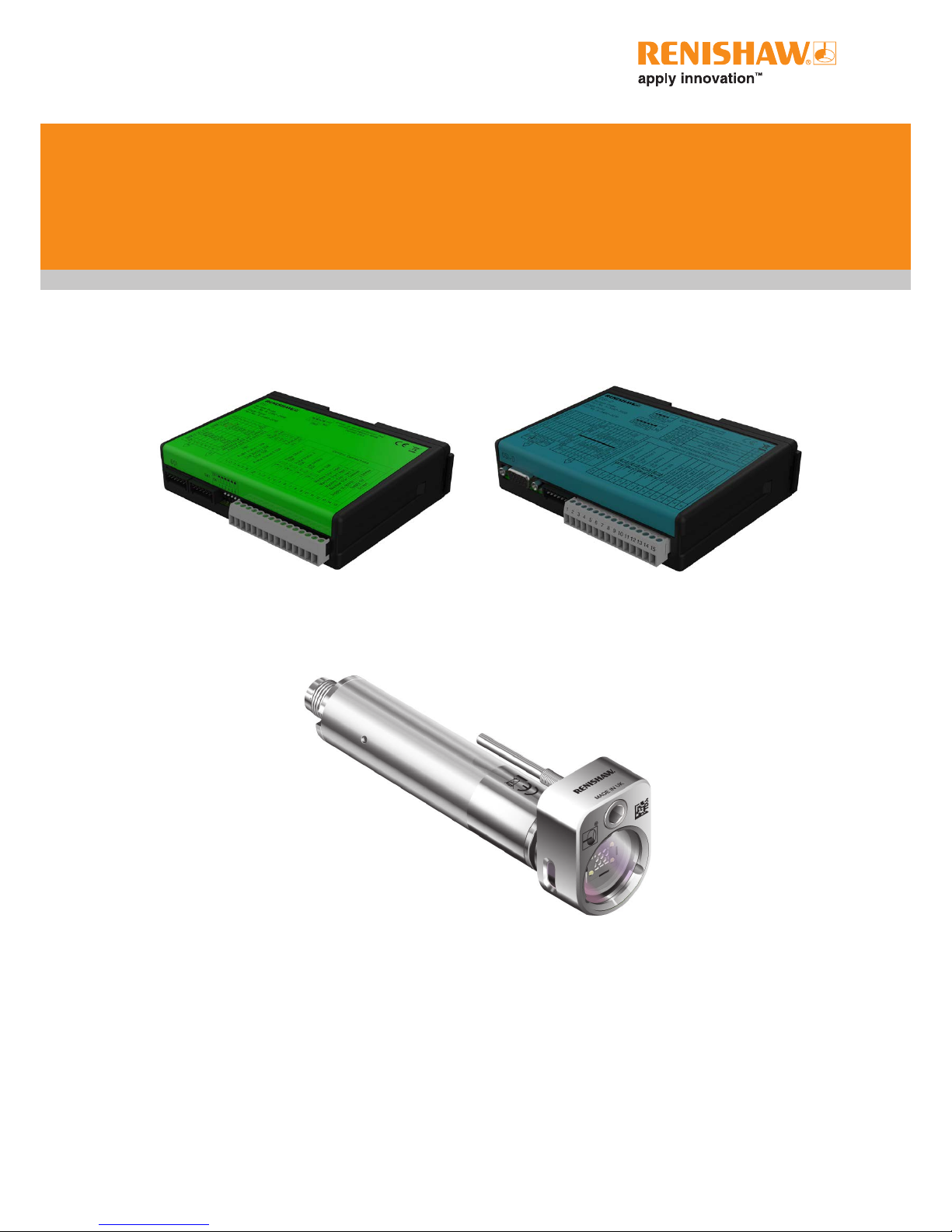
OSI/OSI-D with OMM-2C multiple optical
probe interface system
Installation guide
H-5991-8504-03-A
Page 2

Renishaw part no: H-5991-8504-03-A
First issued: 05.2017
Revised: 02.2019
© 2017–2019 Renishaw plc. All rights reserved.
This document may not be copied or reproduced
in whole or in part, or transferred to any other
media or language, by any means, without the
prior written permission of Renishaw plc.
The publication of material within this document
does not imply freedom from the patent rights of
Renishaw plc.
Page 3

i
Contents
Before you begin .............................................................1.1
Before you begin
............................................................1.1
Disclaimer
..............................................................1.1
Trade marks
.............................................................1.1
Warranty
................................................................1.1
Changes to equipment
.....................................................1.1
CNC machines
...........................................................1.1
Care of the system components
.............................................1.1
Patents
.................................................................1.2
OSI EU declaration of conformity
...............................................1.3
OSI-D EU declaration of conformity
.............................................1.3
OMM-2C EU declaration of conformity
...........................................1.3
WEEE directive
.............................................................1.3
REACH regulation
...........................................................1.3
FCC information to user (USA only)
.............................................1.4
Safety
....................................................................1.5
OSI/OSI-D with OMM-2C basics ...............................................2.1
Introduction
................................................................2.1
OSI-D interface
...........................................................2.1
OSI/OSI-D inputs
............................................................2.2
OSI/OSI-D outputs
..........................................................2.2
OSI components
............................................................2.3
OSI-D components
..........................................................2.4
OMM-2C (A) connector (7-way/15-way)
........................................2.5
OMM-2C (B) connector (7-way)
..............................................2.5
Control connector block (15-way)
.............................................2.5
Switch SW1 output conguration
.............................................2.6
Switch SW2 output conguration
.............................................2.7
OSI/OSI-D input mode congurations
............................................2.8
Single probe mode
........................................................2.8
Multiple probe mode
.......................................................2.8
Page 4

OSI/OSI-D with OMM-2C installation guide
ii
Contents
Switch-on / switch-off method ...............................................2.9
Start-up times ............................................................ 2.9
Synchronisation recovery ...................................................2.9
Multiple probe mode timing diagrams ........................................2.10
OSI/OSI-D output waveforms .................................................2.11
OSI/OSI-D dimensions ......................................................2.12
OSI/OSI-D specification .....................................................2.12
OMM-2C visual diagnostics – system status LEDs .................................2.13
START SIGNAL (blue, yellow, violet) .........................................2.14
ACTIVE SYSTEM (blue, yellow, violet) .......................................2.14
ERROR and STANDBY (red) ...............................................2.14
OVERCURRENT (ashing red) .............................................2.14
CORRUPTED SIGNAL (white) ..............................................2.14
OMM-2C dimensions ........................................................2.15
OMM-2C specification .......................................................2.15
OSI/OSI-D with OMM-2C system used in single probe mode .........................2.16
OSI/OSI-D with OMM-2C system used in multiple probe mode .......................2.17
System installation ...........................................................3.1
Typical OMM-2C system installation .............................................3.1
Introduction .............................................................3.1
Single conguration .......................................................3.1
Tandem conguration ......................................................3.2
OMM-2C application ......................................................3.3
OMM-2C cable ...........................................................3.3
Mounting the OSI/OSI-D to a DIN rail ............................................3.4
Performance envelope of OMM-2C with OMP600 or OMP60 ..........................3.5
Performance envelope of OMM-2C with OMP400, OMP40-2 or OLP40 ..................3.6
Performance envelope of OMM-2C with OTS ......................................3.7
Wiring diagram (with output groupings shown) .....................................3.8
Integral airblast installation (optional) ............................................3.9
Integral airblast application ..................................................3.9
Connecting and purging the air supply .........................................3.9
Maintenance .................................................................4.1
Maintenance ...............................................................4.1
Cleaning the interface .....................................................4.1
Removing the OMM-2C ....................................................4.2
Maintenance – air regulator unit ..............................................4.2
Page 5

iii
Contents
Fault-finding .................................................................5.1
Parts list .....................................................................6.1
Page 6

OSI/OSI-D with OMM-2C installation guide
iv
Contents
This page is intentionally left blank.
Page 7

1.1
Before you begin
Before you begin
Disclaimer
RENISHAW HAS MADE CONSIDERABLE
EFFORTS TO ENSURE THE CONTENT OF THIS
DOCUMENT IS CORRECT AT THE DATE OF
PUBLICATION BUT MAKES NO WARRANTIES
OR REPRESENTATIONS REGARDING
THE CONTENT. RENISHAW EXCLUDES
LIABILITY, HOWSOEVER ARISING, FOR ANY
INACCURACIES IN THIS DOCUMENT.
Trade marks
RENISHAW and the probe symbol used in the
RENISHAW logo are registered trade marks of
Renishaw plc in the United Kingdom and other
countries. apply innovation and names and
designations of other Renishaw products and
technologies are trade marks of Renishaw plc or
its subsidiaries.
All other brand names and product names used
in this document are trade names, trade marks, or
registered trade marks of their respective owners.
Warranty
Equipment requiring attention under warranty
must be returned to your equipment supplier.
Unless otherwise specifically agreed in writing
between you and Renishaw, if you purchased
the equipment from a Renishaw company, the
warranty provisions contained in Renishaw’s
CONDITIONS OF SALE apply. You should consult
these conditions in order to find out the details
of your warranty but, in summary, the main
exclusions from the warranty are if the equipment
has been:
• neglected, mishandled or inappropriately used;
or
• modified or altered in any way except with the
prior written agreement of Renishaw.
If you purchased the equipment from any other
supplier, you should contact them to find out what
repairs are covered by their warranty.
Changes to equipment
Renishaw reserves the right to change equipment
specifications without notice.
CNC machines
CNC machine tools must always be operated by
fully trained personnel in accordance with the
manufacturer's instructions.
Care of the system components
Keep system components clean and treat with
care. Do not apply labels to the front of the
OMM-2C or otherwise obstruct the window.
Page 8

OSI/OSI-D with OMM-2C installation guide
1.2
Before you begin
EP 0974208
EP 1503524
JP 4294101
US 6839563
Patents
Features of OMM-2C and OSI/OSI-D (and
features of similar products) are the subject of
one or more of the following patents and/or patent
applications:
Page 9

1.3
Before you begin
C
OSI EU declaration of conformity
Renishaw plc declares under its sole responsibility
that the OSI is in conformity with all relevant
Union legislation.
The full text of the EU declaration of conformity is
available at:
www.renishaw.com/mtpdoc
OSI-D EU declaration of
conformity
Renishaw plc declares under its sole responsibility
that the OSI-D is in conformity with all relevant
Union legislation.
The full text of the EU declaration of conformity is
available at:
www.renishaw.com/mtpdoc
OMM-2C EU declaration of
conformity
Renishaw plc declares under its sole responsibility
that the OMM-2C is in conformity with all relevant
Union legislation.
The full text of the EU declaration of conformity is
available at:
www.renishaw.com/mtpdoc
C
WEEE directive
The use of this symbol on Renishaw products
and/or accompanying documentation indicates
that the product should not be mixed with
general household waste upon disposal. It is the
responsibility of the end user to dispose of this
product at a designated collection point for waste
electrical and electronic equipment (WEEE) to
enable reuse or recycling. Correct disposal of
this product will help to save valuable resources
and prevent potential negative effects on the
environment. For more information, please contact
your local waste disposal service or Renishaw
distributor.
REACH regulation
Information required by Article 33(1) of Regulation
(EC) No. 1907/2006 (“REACH”) relating to
products containing substances of very high
concern (SVHCs) is available at:
www.renishaw.com/REACH
C
Page 10

OSI/OSI-D with OMM-2C installation guide
1.4
Before you begin
FCC information to user (USA
only)
47 CFR Section 15.19
This device complies with part 15 of the FCC
Rules. Operation is subject to the following two
conditions:
1. This device may not cause harmful
interference, and
2. This device must accept any interference
received, including interference that may
cause undesired operation.
47 CFR Section 15.21
The user is cautioned that any changes or
modifications not expressly approved by
Renishaw plc or authorised representative could
void the user’s authority to operate the equipment.
47 CFR Section 15.105
This equipment has been tested and found to
comply with the limits for a Class A digital device,
pursuant to part 15 of the FCC Rules. These limits
are designed to provide reasonable protection
against harmful interference when the equipment
is operated in a commercial environment. This
equipment generates, uses, and can radiate
radio frequency energy and, if not installed
and used in accordance with the instruction
manual, may cause harmful interference to radio
communications. Operation of this equipment
in a residential area is likely to cause harmful
interference in which case the user will be
required to correct the interference at his own
expense.
Page 11

1.5
Before you begin
Safety
Information to the user
In all applications involving the use of machine
tools or CMMs, eye protection is recommended.
The OMM-2C has a glass window. Handle with
care if broken to avoid injury.
Information to the machine supplier/
installer
It is the machine supplier's responsibility to
ensure that the user is made aware of any
hazards involved during operation, including those
mentioned in Renishaw product literature, and to
ensure that adequate guards and safety interlocks
are provided.
Under certain circumstances, the probe signal
may falsely indicate a probe seated condition. Do
not rely on probe signals to halt the movement of
the machine.
Information to the equipment installer
All Renishaw equipment is designed to comply
with the relevant EU and FCC regulatory
requirements. It is the responsibility of the
equipment installer to ensure that the following
guidelines are adhered to, in order for the product
to function in accordance with these regulations:
• any interface MUST be installed in a position
away from any potential sources of electrical
noise, i.e. power transformers, servo drives etc;
• all 0V/ground connections should be
connected to the machine “star point” (the “star
point” is a single point return for all equipment
ground and screen cables). This is very
important, and failure to adhere to this can
cause a potential difference between grounds;
• all screens must be connected as outlined in
the user instructions;
• cables must not be routed alongside high-
current sources, i.e. motor power supply cables
etc, or be near high-speed data lines;
• cable lengths should always be kept to a
minimum.
• the dc supply to this equipment must be
derived from a source which is approved to
IEC/BS/EN 60950-1.
Equipment operation
If this equipment is used in a manner not specified
by the manufacturer, the protection provided by
the equipment may be impaired.
Optical safety
This product contains LEDs that emit both visible
and invisible light.
OMM-2C is ranked Risk Group: Exempt (safe by
design).
The product was evaluated and classified using
the following standard:
BS EN 62471:2008 The photobiological
(IEC 62471:2006) safety of lamps and lamp
systems.
Renishaw recommends that you do not stare at or
look directly into any LED device, irrespective of
its risk classification.
Page 12

OSI/OSI-D with OMM-2C installation guide
1.6
Before you begin
This page is intentionally left blank.
Page 13

2.1
Introduction
CNC machine tools using Renishaw spindle
probes with optical signal transmission for
workpiece inspection, or tool setters with optical
signal transmission, require an interface system
to convert the signals from the probe into
voltage-free solid state relay (SSR) outputs for
transmission to the CNC machine controller.
Typically installed within the CNC machine
controller’s cabinet and located away from
sources of interference such as transformers and
motor controls, the OSI can draw its power from
the machine’s nominal 12 Vdc to 30 Vdc supply.
The OSI has an input voltage range of 12 Vdc to
30 Vdc. The supply is protected by a 1.1 A selfresetting fuse (the current, when connected to
an OMM-2C, is either 400mA max. @ 12 V or
200 mA max. @ 24 V with tandem OMM-2C). To
reset the fuse, remove the power then identify and
rectify the cause of the fault.
The OSI can be used with either a single or
tandem OMM-2C configuration, housed within
the machining environment. The OMM-2C is
an optical receiver designed for fitment in the
machine spindle. It transmits control signals to the
spindle probe or tool setter, and receives probe
data signals for onward transmission to the OSI
and CNC controller. Power is supplied from the
OSI interface. Visual indication of system status is
provided via the LEDs located on the OMM-2C.
The OSI with OMM-2C system operates using
a ‘modulated’ optical transmission mode and is
compatible with machine probes that also operate
in ‘modulated’ mode.
When in operation, the OMM-2C displays its
present status via three multi-coloured LEDs
located behind the front window (see “OMM-2C
visual dignostics – system status LEDs” on page
2.12).
OSI/OSI-D with OMM-2C basics
OSI-D interface
The OSI-D interface is a variant of the standard
OSI interface, and has been designed for easy
installation to CNC machine controllers using a
15-way HD D type connector for probe input.
The OSI-D interface shares all functionality
and wiring connections with the standard OSI
interface, the only difference being the OMM-2C
connector (A).
NOTE: Throughout this installation guide, the term
OSI and any OSI images refers to both OSI or
OSI-D, unless otherwise specied.
Page 14

OSI/OSI-D with OMM-2C installation guide
2.2
OMM-2C basics
OSI/OSI-D inputs
There are three inputs:
• Probe 1 start
• Probe 2 start
• Probe 3 start
Switch SW2 can be configured to accept either
a pulsed output or level output from the machine
control.
Probe 1 start
Level 8 V to 30 V (4 mA @ 15 V, 7 mA @ 24 V)
When the input is active, the probe is
switched on.
Pulsed 8 V to 30 V (4 mA @ 15 V, 7 mA @ 24 V)
The probe toggles between being
switched on and off. The minimum pulse
width is 10ms.
Probe 2 and probe 3 start
Level 10 V to 30 V (10 mA @ 24 V)
When the input is active, the probe is
switched on.
Pulsed 10 V to 30 V (10 mA @ 24 V)
The probe toggles between being
switched on and off. The minimum pulse
width is 10ms.
The OSI uses level and pulsed machine inputs to
define the active probe. When the respective input
is active, the probe is switched on.
If all inputs are simultaneously active, the system
will default to error.
OSI/OSI-D outputs
There are four outputs:
• Probe status 1 (SSR)
• Probe status 2 (SSR)
• Error (SSR)
• Low battery (SSR)
All outputs can be inverted by using switch SW1,
(see “Switch SW1 output conguration” on page
2.5).
Probe status 1, Error, Low battery (SSR):
• ‘On’ resistance = 50 W max.
• Load voltage = 40 V max.
• Load current = 100 mA max.
Switching times (with 10 mA load)
• Open to closed = 100 µs max.
• Closed to open = 25 µs max.
Both probe status outputs indicate the status
of the selected probe (only one probe can be
selected at a time). They are both individually
configurable.
The OMM-2C LEDs will start flashing red when an
output overload has occurred. Probe status output
will be triggered (SSR open). If this occurs, turn
off the power supply and remove the source of the
problem. Turning on the power supply will reset
the OSI.
CAUTIONS:
Power supply voltage
Do not exceed 30 V between the following:
• the 0 V and the screen wire;
• the 12 V to 30 V supply wire and screen wire;
• the 12 V to 30 V supply wire and 0V wires.
This could result in permanent damage to the
OSI, OMM-2C and/or the power supply.
The use of in-line fuses at the machine cabinet
end is recommended to provide protection for the
OSI, OMM-2C and cable.
Screen connection
A good connection must be made to the machine
ground (‘star point’).
Output
Ensure the output from the OSI does not exceed
the specied current ratings.
Page 15
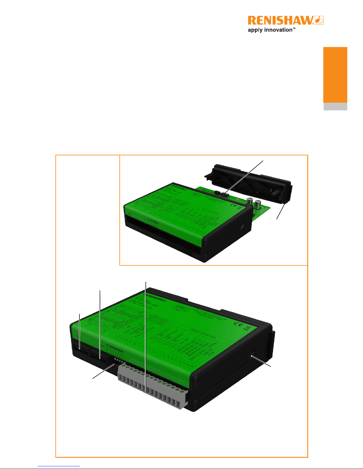
OSI components
The following components are housed within
the front face of the OSI (as shown in the figure
below):
• OMM-2C (A) connector (7-way);
• OMM-2C (B) connector (7-way);
• Control connector block (15-way);
• SSR configuration switch SW1.
OMM-2C (A)
connector
(7-way)
Control connector
block (15-way)
OMM-2C (B)
connector
(7-way)
SSR configuration
switch SW1
Cover tab –
depress to
remove cover
The following components are housed within the
body of the OSI:
• Mode configuration switch SW2.
Access to switch SW1 and switch SW2 is required
during installation only.
Mode configuration
switch SW2
Removable cover
(used to access SW2)
2.3
OMM-2C basics
Page 16
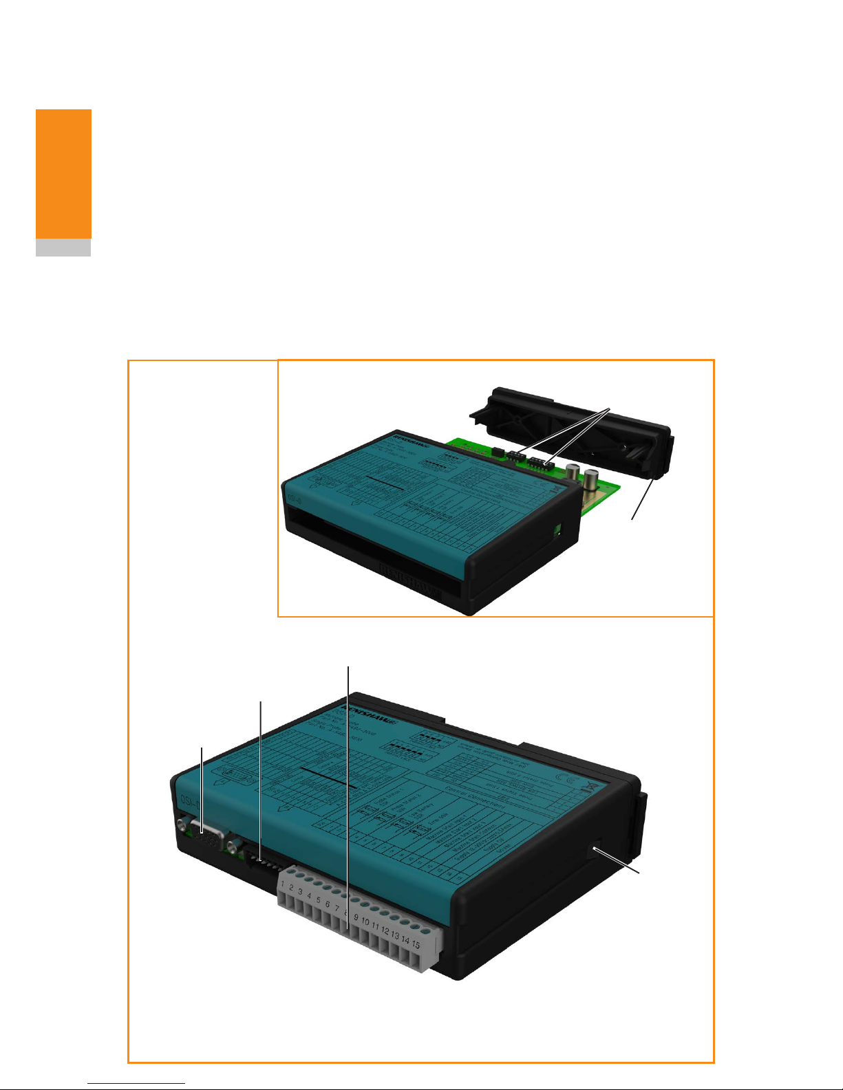
OSI-D components
The following components are housed within the
front face of the OSI-D (as shown in the figure
below):
• OMM-2C (A) connector (15-way HD D type);
• OMM-2C (B) connector (7-way);
• Control connector block (15-way);
OMM-2C (A)
connector
(15-way HD D type)
Control connector
block (15-way)
OMM-2C (B)
connector
(7-way)
Cover tab –
depress to
remove cover
The following components are housed within the
body of the OSI-D:
• SSR configuration switch SW1.
• Mode configuration switch SW2.
Access to switch SW1 and switch SW2 is required
during installation only.
Mode configuration
switches SW1 and SW2
Removable cover
(used to access SW1
and SW2)
OSI/OSI-D with OMM-2C installation guide
2.4
OMM-2C basics
Page 17

OMM-2C (A) connector (7-way/15-way)
OSI
This is a seven-pin connector and is designed to
connect to the Renishaw OMM-2C.
OSI-D
This is a fifteen-pin D type connector and is
designed to connect to the Renishaw OMM-2C.
OMM-2C (B) connector (7-way)
This is a seven-pin connector and is designed to
connect to the Renishaw OMM-2C.
Control connector block (15-way)
This is a fifteen-pin connector and is designed to
connect the OSI to the CNC machine controller
and appropriate power supply as follows:
Pins 1 and 2 are used to connect the ‘Probe
status 1 SSR’ function.
Pins 3 and 4 are used to connect the ‘Probe
status 2 SSR’ function.
Pins 5 and 6 are used to connect the ‘Low battery
SSR’ function.
Pins 7 and 8 are used to connect the ‘Error SSR’
function.
Pins 9 to 12 are used to supply a start signal to
the probe:
• pin 9 is used to transmit a ‘Machine
startinput1’ signal;
• pin 10 is used to transmit a ‘Machine
startinput2’ signal;
• pin 11 is used to transmit a ‘Machine
startinput3’ signal;
• pin 12 is used as ‘Machine start common’.
Pins 13 to 15 are used to supply power and
screen earth to the interface.
2.5
OMM-2C basics
Page 18

Switch SW1 output conguration
Switch SW1 enables the user to configure the
probe system SSR outputs.
Pin SW1 ON OFF
1
Probe status 1 SSR
Pulse Level
2 Normally open Normally closed
3 Low battery SSR Normally open Normally closed
4 Error SSR Normally open Normally closed
5
Probe status 2 SSR
Pulse Level
6 Normally open Normally closed
Factory switch settings shown
are for A-5492-2000
(multiple probe mode)
CAUTION: Take electrostatic discharge (ESD) precautions when handling the PCB.
OSI
Factory switch settings shown
are for A-5492-3000
(multiple probe mode)
OSI-D
OSI/OSI-D with OMM-2C installation guide
2.6
OMM-2C basics
Page 19

Switch SW2 output conguration
Switch SW2 enables the user to configure the OSI
to be used in either single probe mode or multiple
probe mode.
Factory switch settings
shown are for A-5492-2000
(multiple probe mode)
Mode
Switch settings
POLE
Visual
representation
1 2 3 4
Single probe mode, Auto Start off, pulsed machine
M-code.
(Factory setting for A-5492-2010 and A-5492-3010)
ON OFF OFF OFF
Single probe mode, Auto Start off, level machine M-code. ON OFF OFF ON
Single probe mode, Auto Start on. ON ON OFF OFF
Multiple probe mode, two machine M-codes, short time
delay of 10 ms.
OFF ON OFF OFF
Multiple probe mode, two machine M-codes, medium
time delay of 50 ms.
OFF ON ON OFF
Multiple probe mode, two machine M-codes, long time
delay of 100 ms.
OFF ON OFF ON
Multiple probe mode, three machine M-codes, level start.
(Factory setting for A-5492-2000 and A-5492-3000)
OFF OFF ON ON
Multiple probe mode, three machine M-codes, common
start, pulsed machine output.
OFF OFF OFF OFF
Multiple probe mode, three machine M-codes, common
start, level machine output.
OFF OFF OFF ON
OSI
Factory switch settings shown
are for A-5492-3000
(multiple probe mode)
OSI-D
2.7
OMM-2C basics
Page 20

OSI/OSI-D input mode
congurations
Single probe mode
Single probe mode enables one Renishaw probe
to be operated. The probe should be configured as
Probe 1.
Single probe mode provides the option for Auto
Start to be selected. With Auto Start on, the
system will send a start signal once every second
if the probe is off and does not require a CNC
machine output.
Auto Start should only be used when no output
from the machine control is available. If Auto
Start is selected, care should be taken to ensure
system signals are not being received from
probing systems on other machines.
If Auto Start is off, the interface will respond to an
output from the machine controller. Switch SW2
can be configured to accept either a pulsed output
or a level output.
In pulsed mode the interface will react to a pulse
width of 10 ms minimum from a leading edge
signal.
In level mode the probe will be off when the level
is low, and on when the level is high.
Multiple probe mode
Multiple probe mode enables two or three
Renishaw probes to be operated. This can be
achieved by using either two or three outputs from
the machine controller.
If two machine outputs (for three probes) are
used, a coded switch-on technique is used to
switch on / switch off the selected probe. When
using this technique, it is necessary for the two
machine outputs to be sent in short succession
by the controller. To allow for a delay between the
machine outputs, three user-selectable options
are provided:
• a short time delay of 10 ms;
• a medium time delay of 50 ms;
• a long time delay of 100 ms.
If three machine outputs are used, the following
start configurations are available which provide
flexibility for interface integration.
Dedicated start (level mode)
In dedicated start, a machine start input is
required per probe that is configured for optical
switch-on.
Machine start
inputs
Probe selected
P1 P2 P3
None
¬
Probe 1 on
¬
Probe 2 on
¬
Probe 3 on
¬ Machine start input active. Any attempt to switch on more
than one probe simultaneously will result in an error
condition.
Common start (level mode)
In common start (level mode), machine start
inputs P2 and P3 are used to select the probe,
and machine start input P1 is used to start the
selected probe. All inputs are level.
Machine start inputs
P1, P2 and P3
Probe
selected
Probe
start
P1
Probe selection
inputs
P2 P3
¬
Probe 1
¬ ¬
Probe 2
¬ ¬
Probe 3
¬ Machine start input active.
When P1 is off, all probes are off.
When P1 is active, the selected probe will be on.
NOTE: Any change to the probe selection inputs
P2 and P3 whilst the probe is operating will result
in an error condition.
OSI/OSI-D with OMM-2C installation guide
2.8
OMM-2C basics
Page 21

Common start (pulsed mode)
In common start (pulsed mode), machine start
inputs P2 and P3 are level inputs used to select
the probe. Machine start input P1 is a pulsed input
used to start the selected probe.
Machine start inputs
P1, P2 and P3
Probe
selected
Probe
start
P1
Probe selection
inputsV
P2V P3V
Probe 1
¬
Probe 2
¬
Probe 3
Machine start input pulsed, so the selected probe will
change state.
V Probe selection inputs are level signals.
¬ Machine start input active.
NOTES:
OMP600, OMP400, OMP60, OMP40-2, OLP40
or OTS can be congured as Probe 1, Probe 2 or
Probe 3.
For more information, see your probe installation
guide or contact your local Renishaw ofce.
Switch-on / switch-off method
Single probe mode
In pulsed or level mode, the following switch-on /
switch-off methods may be used.
• Optical on / optical off
• Optical on / time off
• Spin on / spin off
• Spin on / time off
• Shank switch on / shank switch off
For Auto Start, only the following switch-on /
switch-off method may be used.
• Optical on / time off
Multiple probe mode
In multiple probe mode, only the following switchon / switch-off method may be used.
• Optical on / optical off
Start-up times
For information on probe start-up times, see
“Multiple probe mode timing diagrams” on page
2.9.
The switch-off time is 0 seconds.
When changing from one selected probe to
another, allow 1 second between the cancelling
of one machine start input (machine output) and
raising of the other start input.
Synchronisation recovery
Under abnormal operating situations, when used
in multiple probe mode, the system may lose
synchronisation between the receiver and the
probes. An internal synchronisation recovery
will be initiated when the next machine input is
received.
The maximum time for system recovery from
an abnormal operating situation is 7.5 seconds.
Such a time delay could cause a machine alarm if
controllers require ready signals within less than
5.5 seconds.
2.9
OMM-2C basics
Page 22

Two machine outputs (for three probes)
Three machine outputs (Dedicated start)
Three machine outputs (Common start / pulsed mode )
Three machine outputs (Common start / level mode)
Probe start-up time = 410 ms max. for kinematic probes and
1 s max. + delay (10, 50, 100 ms) for strain gauge probes.
Probe start-up time = 410 ms max. for kinematic probes and
1 s max. for strain gauge probes.
Probe start-up time = 410 ms max. for kinematic probes and
1 s max. for strain gauge probes.
Probe start-up time = 410 ms max. for kinematic probes and
1 s max. for strain gauge probes.
Machine start
input 1
Machine start
input 1
Machine start
input 1
Machine start
input 1
Machine start
input 2
Machine start
input 2
Machine start
input 2
Machine start
input 2
Machine start
input 3
Machine start
input 3
Machine start
input 3
Start
Stop
Stop
10, 50, 100 ms
delay options
Probe 1
Probe 1
Probe 1
Probe 1
Probe 2
Probe 2
Probe 2
Probe 2
Probe 3
Probe 3
Probe 3
Probe 3
Multiple probe mode timing diagrams
Start
Stop
Start
Start
Stop
Start
Stop
Start
Stop
Start
Stop
Start
Stop
Start
Stop
Start
Stop
Start
Stop
Start
Stop
Start
Stop
Start
Stop
Start
Stop
Start
Stop
10, 50, 100 ms
delay options
OSI/OSI-D with OMM-2C installation guide
2.10
OMM-2C basics
Page 23

Signal delays
Transmission delay From probe trigger to output change of state = 2.5 ms max.
OSI/OSI-D output waveforms
NOTE: Pulsed outputs are 40 ms ±1 ms duration
SSR closed
SSR open
Probe
OSI
SSR
output
SSR closed
SSR open
Normally
open
Probe status
1 & 2 (level)
Probe status
1 & 2 (pulsed)
Normally
open
Probe
switch
on
Seated
Stand-
by
Probe
trigger
Triggered
Probe
reseat
Seated Error
e.g.
low signal
Stand-by
Low
battery
Probe
switch
on
Normally
open
Low
battery
Normally
closed
Error
SSR closed
SSR open
SSR closed
SSR open
2.11
OMM-2C basics
Page 24

OSI/OSI-D dimensions
OSI/OSI-D specification
110 (4.33)
134 (5.28)
35 (1.38)
Dimensions given in mm (in)
Principal application The OSI processes signals from RENGAGE™ or standard probes
via single or tandem OMM-2Cs or OMM-2s and converts them into
machine outputs, which are then transmitted to the CNC control. The
system allows up to three probes to be used with one interface.
Transmission type Infrared optical transmission (modulated)
Probes per system Up to three
Supply voltage 12 Vdc to 30 Vdc
Supply current 200 mA max. @ 24 V with tandem OMM-2C
Configurable M-code input Pulsed or level
Output signals
Probe Status 1, Probe Status 2, Low Battery, Error
Voltage-free solid-state relay (SSR) outputs, congurable as normally
open or normally closed.
Input/output protection Supply protected by a 1.1 A resettable fuse.
Outputs protected by overcurrent protection circuit.
Environment
(as defined in
BS EN 61010-1:2001)
IP rating IP20 (BS 5490, EN/IEC 60529)
Storage temperature
−10 °C to +70 °C (14 °F to 158 °F)
Operating temperature +5°C to +55°C (+41°F to +131°F)
OSI/OSI-D with OMM-2C installation guide
2.12
OMM-2C basics
Page 25

2.13
OMM-2C basics
OMM-2C visual diagnostics –
system status LEDs
A visual indication of system status is provided by
three LEDs. Indication is provided for:
• START SIGNAL;
• ACTIVE SYSTEM;
• ERROR and STANDBY;
• OVERCURRENT;
• CORRUPTED SIGNAL.
Status LEDs
Page 26

OSI/OSI-D with OMM-2C installation guide
2.14
OMM-2C basics
START SIGNAL (blue, yellow, violet)
This will flash when a machine control start signal
is commanded; blue denotes Probe 1 start, yellow
denotes Probe 2 start and violet denotes Probe 3
start.
A successful probe start will cause the ‘ACTIVE
SYSTEM’ LED to become lit and a failed start will
result in an ‘ERROR’ being displayed.
ACTIVE SYSTEM (blue, yellow, violet)
In single probe mode the system will be constantly
lit blue to show that the input is active.
In multiple probe mode the system will be
constantly lit blue to denote Probe 1 is active,
yellow to denote Probe 2 is active and violet to
denote Probe 3 is active.
If any ambiguous start information is received, the
system will flash repeatedly (blue – yellow – violet
– cyan) in sequence until the start input is cleared.
ERROR and STANDBY (red)
When lit constant red it indicates a transmission
error condition, such as optical beam obstructed /
probe out of optical range / probe switched off
(standby) / dead battery.
OVERCURRENT (ashing red)
The system will start flashing red when an output
overload has occurred. All outputs will be switched
off.
If this occurs, turn off the power and remove
the source of the problem. Turning on the power
supply will reset the system.
CORRUPTED SIGNAL (white)
If the system displays a constant white LED, then
either a second modulated probe signal has been
received or the probe trigger instant has been
delayed due to interference or a weak probe
signal.
NOTE: In single probe mode the constant white
error condition resulting from the loss of a good
probe signal will persist until the machine start is
activated or 1 hour has elapsed. In multiple probe
mode the indication will persist until the active
system input (Probe1, Probe 2 or Probe 3) is
deactivated.
Command LED display
Error / standby
Operating Probe 1
Probe 2
Probe 3
Overcurrent protection
Failed start (1 second
ash of attempted
probe start)
Probe 1
Probe 2
Probe 3
Invalid start signal
Interference or second probe received
Single probe mode
with Auto Start
Auto Start mode only standby
Auto Start mode second probe signal received
Key to the symbols
LED short flash
LED solid on
Page 27

OMM-2C specification
Principal application The OMM-2C transmits control signals to the probe and receives probe
data signals for onward transmission to the OSI and CNC control.
Transmission type Infrared optical transmission (modulated)
Probes per system Up to three
Compatible probes OMP40-2, OMP40M, OLP40, OMP60, OMP60M, OMP400, OMP600 and
OTS
Operating range Up to 3 m (9.8 ft)
Weight (excluding
cable)
with airblast 80 g (2.82 oz)
without airblast 80 g (2.82 oz)
Cable
(not supplied) Specification Ø4.75 mm (0.19 in), 12 core screened cable
each core 7 × 0.1 mm
Length 8 m (26.2 ft), 15 m (49.2 ft)
Mounting Specifically designed for mounting in the machine spindle.
Diagnostic LEDs Start, error, active system and signal condition.
Pneumatic supply Ø3 mm (0.12 in) pneumatic fitting, 9 bar (130.5 psi) max. The air supply to
the OMM-2C must conform to ISO 8573-1: Class 1.7.2.
Environment IP rating IPX6 (EN/IEC 60529) [for product]
IPX8 (EN/IEC 60529) [for glass window]
IK rating IK04 (EN/IEC 62262) [for glass window]
Storage temperature
−25 °C to +70 °C (−13 °F to +158 °F)
Operating temperature +5°C to +55°C (+41°F to +131°F)
2.15
OMM-2C basics
OMM-2C dimensions
Dimensions mm (in)
M4 × 11.0 (0.43) MIN
Ø20.0 (0.79)
Ø18.7 (0.74)
Bore diameter
Ø18.02 (0.709)
Ø18.00 (0.708)
30.0 (1.18)
30.0 (1.18)
4.8 (0.19)
14.0 (0.55)
11.0 (0.43)
Ø17.7 (0.69)
66.0 (2.60)
22.0
(0.87)
2.8 (0.11) MAX
30°
15°
Ra 1.6 (64)
10.0 (0.39)
Installation
detail
Binder connector
(series 702)
09-0427-90-08
× 6.0 (0.24) MIN DEPTH
Page 28

OMM-2C
OSI
OMP
CNC machine control
OSI/OSI-D with OMM-2C installation guide
2.16
OMM-2C basics
OSI/OSI-D with OMM-2C system
used in single probe mode
The system can be used with any Renishaw
OMP, OLP or OTS probe system. The following
descriptions use OMP60 as an example.
In single probe mode, the system will interface a
single Renishaw machine probe with the machine
controller. It is possible for either a single OMM-2C
or tandem OMM-2C/OMM-2 to be connected to
the OSI. The selected configuration will depend on
the machine application.
When the OMM-2C is used in tandem, both
receivers will simultaneously provide an indication
of system status. Tandem OMM-2C can be used
on twin-spindle machines to maintain probe
communications when a probe is in the second
spindle. Tandem OMM-2C and OMM-2 allows
for uninterrupted probe communications where
line-of-sight issues become apparent when only a
single receiver is used.
The illustration below shows a typical OSI with
OMM-2C system used in single probe mode.
Alternatively, the system can be used to interface
a single OTS (optical tool setter) instead of the
OMP (optical machine probe) shown.
Page 29

OSI/OSI-D with OMM-2C system
used in multiple probe mode
In multiple probe mode, the system will
sequentially interface up to three separate
Renishaw optical machine probes with the
machine controller. It is possible to have either a
single OMM-2C or a tandem OMM-2C or OMM-2
configuration to best suit the application.
Application of the system in multiple probe mode
is suited to many machine applications. Typical
examples are as follows:
1 × OMP with 2 × OTS (optical tool setter)
(illustrated below).
This arrangement is suitable for a machine
application that has a partitioned machining area
with an OTS positioned in each area. An OMP
in the spindle is used in both areas. The OMP is
assigned as Probe 1 and the 2 × OTS assigned
as Probe 2 and Probe 3 .
2 × OMP with 1 × OTS
This arrangement is suitable for a machine
application that requires two different stylus
configurations. The 2 × OMP are assigned as
Probe 1 and Probe 2 and the OTS is assigned as
Probe 3.
3 × OTS
This arrangement is suitable for a pallet loaded
machine application with an OTS installed on
three pallets, each communicating with an
OMM-2C in the machine. The 3 × OTS are
assigned as Probe 1, Probe 2 and Probe 3.
3 × OMP
This arrangement is suitable for a machine
application which requires three different stylus
or probe configurations; for example, 2 × strain
gauge probes and 1 × modular probe. For this
configuration to be compatible, one probe should
have Probe 3 functionality.
OSI
OTS
OTS
OMP
OMM-2C
2.17
OMM-2C basics
Page 30

OSI/OSI-D with OMM-2C installation guide
2.18
OMM-2C basics
This page is intentionally left blank.
Page 31

3.1
System installation
Typical OMM-2C system installation
Introduction
WARNING: Ensure the machine tool is in a safe
condition and power is removed before removing
covers. Only qualied persons should adjust
switches.
The OMM-2C should be mounted as near to the
machine spindle as possible (as shown below).
When mounting the OMM-2C, it is important that
the sealing ring forms a tight seal around the rim
of the bore into which the body of the OMM-2C is
to be located.
CAUTION: Make sure the sealing ring and
air tting screw (if applicable) are clean and
lubricated prior to being mounted in the machine
spindle.
NOTE: Do not overtighten the mounting screw.
Maximum torque is 1.5 Nm (1.11 lbf.ft.).
Single conguration
CNC machining
centre spindle
Cable
CNC
machine
control
OMM-2C
(optical module
machine)
OMP
Stylus
Workpiece
Serial No. V68739
OSI
OTS tool setting probe
Page 32

OSI
OSI-D
For tandem installations
Cable Cable
Cable
OMM-2 (B)
OMM-2C (B)
OMM-2C (A)
OSI-D
To CNC machine control
OSI/OSI-D with OMM-2C installation guide
3.2
System
installation
Tandem conguration
For tandem installations
Cable Cable
Cable
OMM-2 (B)
OMM-2C (B)
OMM-2C (A)
OSI
To CNC machine control
Page 33

3.3
System
installation
OMM-2C application
OSI
A single, tandem or combination of OMM-2C and
OMM-2 configuration can be connected to the
OSI. Each OMM-2 / OMM-2C is connected to the
interface by a 7-way connector block (as shown in
the wiring diagram on page 3.8).
OSI-D
One OMM-2C is connected to connector ‘A’ of the
interface using a 15-way HD D type connector.
The second OMM-2C is connected to connector
‘B’ of the interface using a 7-way connector block
(as shown in the wiring diagram on page 3.8).
A single OMM-2 can be connected to the OSI-D
using a 7-way connector block (as shown in the
wiring diagram on page 3.8).
When a tandem OMM-2 / OMM-2C configuration
is used, there will be a simultaneous indication
of system status on both receivers (for OMM-2C,
see Chapter 2, “OMM-2C basics”, or for OMM-2
see the OSI with OMM-2 multiple optical probe
interface system installation guide (Renishaw part
no. H-5492-8504).
Tandem OMM-2C can be used in machines with
two separate spindles. It is not necessary to
shield one receiver from the other, and operating
envelopes can overlap.
OMM-2C cable
Cable termination
Suitable ferrules should be crimped onto each
cable wire for a more positive connection at the
terminal box.
Standard cable variants
The OMM-2C standard polyurethane cables are
supplied in 8 m (26 ft) and 15 m (49 ft) lengths.
Please contact Renishaw for other cable lengths if
required.
NOTE: The maximum permissible length of cable
is 30 m (98 ft).
Cable specication
Ø4.75 mm (0.19 in), 12 core, screened cable,
each core consisting of 7 × 0.1 mm wires.
Cable sealing
Coolant and dirt are prevented from entering the
OMM-2C by the cable connector. The OMM-2C
cable can be protected against physical damage
by fitting flexible conduit if required.
NOTE: Do not overtighten cable connector.
Maximum torque is 2 Nm (1.48 lbf.ft.).
Page 34

M4 (× 2)
Standard DIN rail mounting
Alternative mounting
79.75
(3.14)
NOTE: Lift spring end plate to attach OSI to DIN rail.
OSI/OSI-D with OMM-2C installation guide
3.4
System
installation
Mounting the OSI/OSI-D to a DIN
rail
Dimensions mm (in)
Page 35

Range m (ft)
Switch on / switch off
Operating – standard power mode
Operating – low power mode
Typical plot at 20 °C (68 °F)
360° transmission around
probe axis in metres (feet)
OMP600 or
OMP60
75°
60°
45°
30°
15°
0°
15°
30°
45°
60°
75°
2.5 (8.2)
2.0 (6.5)
1.5 (4.9)
1.0 (3.3)
0.5 (1.6)
75°
60°
45°
30°
15°
0°
15°
30°
45°
60°
OMM-2C
75°
Optical centre line
3.0 (9.8)
3.5
System
installation
Performance envelope of
OMM-2C with OMP600 or OMP60
Reflective surfaces within the machine cabinet
may increase the signal transmission range.
Coolant residue accumulating on the windows of
the OMM-2C and OMP will have a detrimental
effect on transmission performance. Wipe the
windows clean as often as necessary to maintain
unrestricted transmission.
For best system performance, ensure the
OMM-2C is mounted in a position which is not
directly in front of a light source.
The probe and OMM-2C may deviate from the
optical centre line, provided opposing light cones
always overlap, with transmitters and receivers in
the other’s field of view (eye-to-eye).
In multiple probe mode applications, OMP600 or
OMP60 may be configured as Probe 1, Probe 2 or
Probe 3.
CAUTION: If two systems are operating in close
proximity, take care to ensure that the signals
transmitted from the OMP on one machine are not
received by the OMM-2C on another machine and
vice versa.
2.5 (8.2)
2.0 (6.5)
1.5 (4.9)
1.0 (3.3)
0.5 (1.6)
3.0 (9.8)
Page 36

Typical plot at 20 °C (68 °F)
360° transmission around
probe axis in metres (feet)
Range m (ft)
Switch on / switch off
Operating – standard power mode
Operating – low power mode
Typical plot at 20 °C (68 °F)
360° transmission around
probe axis in metres (feet)
OMP400,
OMP40-2
or OLP40
75°
60°
45°
30°
15°
0°
15°
30°
45°
60°
75°
75°
60°
45°
30°
15°
0°
15°
30°
45°
60°
OMM-2C
75°
Optical centre line
2.5 (8.2)
2.0 (6.5)
1.5 (4.9)
1.0 (3.3)
0.5 (1.6)
OSI/OSI-D with OMM-2C installation guide
3.6
System
installation
Performance envelope of
OMM-2C with OMP400, OMP40-2
or OLP40
Reflective surfaces within the machine cabinet
may increase the signal transmission range.
Coolant residue accumulating on the windows of
the OMM-2C and OMP will have a detrimental
effect on transmission performance. Wipe the
windows clean as often as necessary to maintain
unrestricted transmission.
For best system performance, ensure the
OMM-2C is mounted in a position which is not
directly in front of a light source.
The probe and OMM-2C may deviate from the
optical centre line, provided opposing light cones
always overlap, with transmitters and receivers in
the other’s field of view (eye-to-eye).
In multiple probe mode applications, OMP400
may be configured as Probe 1 or Probe 2 and
OMP40 or OLP40 may be configured as Probe 1,
Probe 2 or Probe 3.
CAUTION: If two systems are operating in close
proximity, take care to ensure that the signals
transmitted from the OMP on one machine are not
received by the OMM-2C on another machine and
vice versa.
2.5 (8.2)
2.0 (6.5)
1.5 (4.9)
1.0 (3.3)
0.5 (1.6)
Page 37

Range m (ft)
Switch on / switch off
Operating – standard power mode
Operating – low power mode
3.7
System
installation
Performance envelope of
OMM-2C with OTS
Reflective surfaces within the machine cabinet
may increase the signal transmission range.
Coolant residue accumulating on the windows
of the OMM-2C and OTS will have a detrimental
effect on transmission performance. Wipe the
windows clean as often as necessary to maintain
unrestricted transmission.
For best system performance, ensure the
OMM-2C is mounted in a position which is not
directly in front of a light source.
The probe system should be positioned so that
the signal transmission is maintained when the
OTS is positioned below the machine spindle.
The OTS and OMM-2C may deviate from the
optical centre line, provided opposing light cones
always overlap, with transmitters and receivers in
the other’s field of view (eye-to-eye).
In multiple probe mode applications, OTS may be
configured as Probe 1, Probe 2 or Probe 3.
CAUTION: If two systems are operating in close
proximity, take care to ensure that the signals
transmitted from the OTS on one machine are not
received by the OMM-2C on another machine and
vice versa.
Typical plot at 20° C (68° F)
Transmission around probe axis
in metres (feet)
OTS
75°
60°
45°
30°
15°
0°
15°
30°
45°
60°
75°
75°
60°
45°
30°
15°
0°
15°
30°
45°
60°
OMM-2C
75°
Optical centre line
2.5 (8.2)
2.0 (6.5)
1.5 (4.9)
1.0 (3.3)
0.5 (1.6)
2.5 (8.2)
2.0 (6.5)
1.5 (4.9)
1.0 (3.3)
0.5 (1.6)
Page 38

Wiring diagram (with output groupings shown)
White
Turquoise
Green
Black
Red
Violet
Screen
OMM-2C
(A)
OSI
OMM-2C
(B)
Probe Status 1 (SSR)
Probe Status 2 (SSR)
Low Battery (SSR)
Error (SSR)
CNC
machine
control
Powe r
supply
Machine star ground point
Machine start common
12 V to 30 V
+ 24 V
0 V
0 V
Power supply (12 V to 30 V)
Screen
1
2
3
4
5
6
7
White
Turquoise
Green
Black
Red
Violet
Screen
Machine start input 1 (Machine output)
Machine start input 2 (Machine output)
Machine start input 3 (Machine output)
1
2
3
4
5
6
7
1
2
3
4
5
6
7
8
9
10
11
12
13
14
15
OSI-D
OSI/OSI-D with OMM-2C installation guide
3.8
System
installation
CAUTIONS:
The power supply 0 V should be terminated at the machine ground (“star point”). If a negative supply is
used, then the negative output must be fused.
The dc supply to this equipment must be derived from a source which is approved to
IEC/BS/EN60950-1.
Renishaw cable part nos.:
A-5314-0015, 8 m (26 ft)
A-5314-0016, 15 m (49 ft)
OMM-2C OSI Colour
Pin 1 Pin 4 Black
Pin 2 Pin 5 Red
Pin 3 Pin 1 White
Pin 4 Pin 2 Turquoise
Pin 5 Pin 3 Green
Pin 6 Pin 6 Violet
Pin 7 Not used Grey
Pin 8 Not used Not used
Shell Pin 7 Screen
View A
View A
View A
OMM-2C OSI-D
Pin 1 Pin 9
Pin 2 Pin 10
Pin 3 Pin 6
Pin 4 Pin 2
Pin 5 Pin 3
Pin 6 Pin 4
Pin 7 Not used
Pin 8 Not used
Shell Shell
Page 39

Integral airblast installation
(optional)
Integral airblast application
The OMM-2C is available with an integral optional
airblast facility. An air supply is connected to the
OMM-2C through the special mounting screw
and the air feed is internally routed to air nozzles
around the OMM-2C front window which assists
with keeping the optical window clear of swarf and
debris.
It is recommended that a switched air supply
is used prior to any probing routine and the air
supply to the OMM-2C is switched off after the
probing routine has finished.
Connecting and purging the air supply
CAUTIONS:
Do not connect the OMM-2C system to an oiled
air supply. Purge all piping prior to connection.
Safety glasses must be worn.
1. Locate a source of clean air that conforms to
ISO 8573-1: Air quality of class 5.9.4.
2. Connect a suitable pipe to the air supply.
3. Before connecting the pipe to the inlet of the
air regulator unit, briefly switch on the air
supply to clear out all debris from the pipe.
4. Connect one end of the Ø4 mm air pipe into
the air regulator unit.
5. Cut the Ø4 mm pipe to length, ensuring that
the length of the pipe is as short as possible
to minimise the drop in air pressure.
6. Temporarily tape over the free end of the pipe
to ensure that no coolant or debris is able to
enter it.
7. Push the free end of the air supply pipe
through the air pipe spring conduit.
8. Remove the tape from the end of the air pipe.
Before connecting the pipe to the inlet of the
OMM-2C unit, briefly switch on the air supply
to clear out any debris from the pipe.
9. Connect the free end of the pipe to the
OMM-2C unit using a 4 mm to 3 mm air
fitting.
NOTE: The integral airblast facility should not be
used as a replacement for routine maintenance
checks or relied on to ensure the optical window is
kept clean of debris and swarf.
3.9
System
installation
OMM-2C
unit
Purge the air supply to dislodge
debris from the pipework
prior to connection, as small
particles may block the air
nozzle.
Air outlet
Air regulator unit
Air supply
Æ
Page 40

This page is intentionally left blank.
OSI/OSI-D with OMM-2C installation guide
3.10
System
installation
Page 41

4.1
Maintenance
Maintenance
You may undertake the maintenance routines
described in these instructions.
Further dismantling and repair of Renishaw
equipment is a highly specialised operation,
which must be carried out at authorised Renishaw
Service Centres.
Equipment requiring repair, overhaul or attention
under warranty should be returned to your
supplier.
Cleaning the interface
Wipe the window of the interface with a clean
cloth to remove machining residue. This should
be done on a regular basis to maintain optimum
transmission.
CAUTION: The OMM-2C has a glass window.
Handle with care if broken to avoid injury.
Page 42

Removing the OMM-2C
WARNING: Ensure the machine tool is in a safe
condition and power is removed before removing
covers. Only qualied persons should work on a
machine tool.
In the event that you need to remove the
OMM-2C, the receiver incorporates a jacking
thread to aid removal.
1. Purge machine air supply (if air blast fitted)
and remove power from the OSI.
2. Clean the OMM-2C prior to disassembly to
ensure no debris enters the unit.
3. Disconnect air pipe from the OMM-2C and
remove cap from both ends (if applicable)
4. Unscrew cable connector from rear of the
OMM-2C and secure.
5. Carefully remove mounting screw/air feed
screw from OMM-2C ensuring ‘O’ rings are
kept clean.
6. Insert an M5 screw (not supplied) into the
threaded mounting hole.
7. Tighten the screw to lift the OMM-2C out of
the machine spindle bore. When clear of the
spindle, remove the screw completely and
refit the original mounting screw / airscrew to
prevent debris entering air chamber.
Maintenance – air regulator unit
The procedures described in this section apply
only to the air regulator system (A-2253-5120)
that is available from Renishaw plc.
Checking the liquid level
Regularly check the level of the accumulated
liquid in each of the filter bowls. It is important that
the level is kept below the filter element.
Draining the liquid
Drain the liquid that has accumulated in the filter
bowls as follows:
1. Make a note of the air supply pressure, then
switch off the air supply. A quantity of liquid
will drain from the bowls.
2. Switch on the air supply and set the pressure
to the value noted in step 1.
3. Repeat steps 1 and 2 until the bowls are
empty.
OSI/OSI-D with OMM-2C installation guide
4.2
Maintenance
Air pressure regulator
filter bowl
Air pressure
adjusting knob
Oil removal
filter bowl
OMM-2C
Mounting
screw
M5 screw
(not supplied)
Page 43

Removing and retting lter elements
Regularly inspect the filter element in each filter
bowl. They should be replaced when dirty or wet
and at least once each year. For each filter bowl,
do this as follows:
1. Make a note of the air supply pressure, then
switch off the air supply.
2. Unscrew the filter bowl by hand (see the
figure on page 4-4).
3. Remove the O-ring from the recess in the
filter bowl. Discard the O-ring.
4. Unscrew and remove the filter element.
5. Fit the replacement filter and, where
applicable, the O-ring. These are shown in
dotted box A in the figure on page 4.4.
6. Fit a new O-ring into the recess in the filter
bowl.
7. Refit the filter bowl and screw hand tight.
8. Switch on the air supply and set the pressure
to the value noted in step 1.
Replacing other service kit components
1. Make a note of the air supply pressure, then
switch off the air supply.
2. Using a 38 mm AF spanner, remove the
regulator head.
3. Remove the components (shown in dotted
box B in the figure on the page 4.4) from the
body of the regulator.
4. Fit the new components to the regulator body.
5. Refit the regulator head and tighten to 7.7Nm
(5.7 lbf.ft).
6. Switch on the air supply and set the pressure
to the value noted in step 1.
4.3
Maintenance
Air pressure regulator filter
bowl
Oil removal
filter bowl
Page 44

OSI/OSI-D with OMM-2C installation guide
4.4
Maintenance
A
B
NOTE: Items shown within dotted boxes A and B
are included in the air lter service kit obtainable
from Renishaw (see the Parts lists on page 6.1).
Page 45

5.1
Fault-finding
Symptom Cause Action
Probe fails to switch on
or switch off.
Installation / CNC program fault. Correct M-code and/or wiring from
machine to OSI and from OSI to
OMM-2C and/or CNC program.
OMM-2C flashes blue,yellow,
violet and cyan due to
ambiguous start information
being received.
Correct M-codes in CNC program
when two are used. To reset the
error, deactivate all active machine
start inputs. Select 50 ms or
100ms delay.
The probe is out of the start
range.
Change the CNC program to bring
the probe within the start range of
the receiver.
The transmission beam is
obstructed.
Clean the receiver window and
remove any obstructions.
Incompatible probe /
probe transmission setting.
Ensure the probe switch-on /
switch-off method is set to optical
on / optical off.
Change the probe or probe setting
to modulated and appropriate start
code.
Incorrect Machine Start setting. Recongure the Machine Start
setting switch SW2.
Dead probe batteries. Replace the probe batteries.
Optical interference is blocking
the start signal.
Remove the source of interference
and ensure that interfering light
does not shine onto the receiver
window or probe window.
Page 46

OSI/OSI-D with OMM-2C installation guide
5.2
Fault-finding
Symptom Cause Action
Probe 2 or Probe 3 fails
to switch on.
OSI in single probe mode. Change OSI to multiple probe
mode.
A time delay exists between
machine inputs from the controller.
Increase selected time delay.
The probe stops in
mid-cycle.
or
An unexpected error
occurs during a
probing cycle.
or
An unexpected trigger
occurs during the
probing cycle.
The transmission beam is
obstructed.
Remove the obstruction.
Optical interference. Remove the source of interference
and ensure that interfering light
does not shine into the receiver
window.
Intermittent wiring fault. Correct wiring.
The probe has moved outside the
reception range.
Change the CNC program to bring
the probe within the reception
range of the receiver.
The probe has not been triggered
for more than 90 minutes.
Restart the probe and ensure
that the probe is not idle for
90minutes.
The probe switches on,
but the OMM-2C LED is
lit red or white.
Interfering light source is shining
directly into the receiver window.
Remove the source of interference
and ensure that the interfering light
does not shine into the receiver
window.
The probe is out of the reception
range.
Change the CNC program to move
the probe into the reception range
of the receiver.
A signal is being received
from a probe on an adjacent
machine tool.
Change the adjacent probe to low
power mode.
Installation / CNC program fault. Check wiring and CNC program.
Page 47

5.3
Fault-finding
Symptom Cause Action
The probe indicates
low battery condition,
but the machine control
does not.
Installation / CNC program fault.
Machine may not have the facility
integrated.
Correct low battery SSR wiring
and/or CNC program.
The machine control
does not respond to the
probe being triggered or
seated.
Probe is not switched on. Attempt to switch it on.
Probe is out of range. Change the CNC program to bring
the probe within the reception
range.
Installation / CNC program fault. Correct M-code and/or wiring from
machine to OSI and from OSI to
OMM-2C and/or CNC program.
A signal is being received
from a probe on an adjacent
machine tool.
Change the adjacent probe to low
power mode.
Probe triggers but
the OMM-2C does not
respond.
The OMP400 or OMP600 has
the 3 second switch-on delay
selected.
Reconfigure the OMP400
or OMP600 to the standard
switch-on delay.
The probe is out of range. Review the performance
envelopes.
The transmission beam is
obstructed.
Check that the probe and receiver
windows are clean, and remove
any obstruction.
The probe is set to legacy
transmission.
Recongure to modulated
transmission.
No air from airblast. No air to OMM-2C. Check air supply to OMM-2C and
rectify.
CNC program fault. Correct CNC program.
Air supply pipe damaged or
kinked.
Check air supply pipe.
Air blast blocked. Unblock air blast.
Page 48

OSI/OSI-D with OMM-2C installation guide
5.4
Fault-finding
This page is intentionally left blank.
Page 49

6.1
Parts list
Item Part number Description
OSI interface A-5492-2000 OSI (multiple probe mode) with DIN rail mounting, terminal
block and quick-start guide.
OSI interface A-5492-2010 OSI (single probe mode) with DIN rail mounting, terminal block
and quick-start guide.
OSI-D interface A-5492-3000 OSI-D (multiple probe mode) with DIN rail mounting, terminal
block and quick-start guide.
OSI-D interface A-5492-3010 OSI-D (single probe mode) with DIN rail mounting, terminal
block and quick-start guide.
OMM-2C
(standard
non-airblast)
A-5991-0001 OMM-2C (non-integrated airblast) with 7-way socket and quick-
start guide.
OMM-2C
(optional airblast)
A-5991-0005 OMM-2C (integrated airblast) with 7-way socket and
quick-start guide.
OSI terminal
block (15-way)
P-CN25-0009 15-way socket terminal for OSI.
OMM-2C terminal
block (7-way)
P-CA79-0021 7-way socket terminal for OMM-2C.
OMM-2C cable A-5314-0015 OMI-2C/OMM-2C cable assembly, with 8 m (26 ft) of cable
(7-way connector not included).
OMM-2C cable A-5314-0016 OMI-2C/OMM-2C cable assembly, with 15 m (49 ft) of cable
(7-way connector not included).
Mounting screw
(standard)
A-5991-0113 Replacement standard mounting screw. For use with
A-5991-0001.
Mounting screw
(air blast option)
A-5991-0112 Replacement mounting screw for the optional integral air blast
OMM-2C. For use with A-5991-0005.
OSI-D cable A-5492-0042 OSI-D 15-way HD D type connector to 15-way D type adaptor,
with 3 m (9.8 ft) of cable.
OSI-D cable A-5492-0043 OSI-D 15-way controller connector to 15 way HD D type
adaptor, with 3 m (9.8 ft) of cable.
OSI-D cable A-5492-0044 OSI-D 15-way controller connector to 15-way D type, with 3 m
(9.8 ft) of cable.
OSI-D cable A-5492-0045 OSI-D to OMM-2C extension cable 15-way HD D type
connector, with 3 m (9.8 ft) of cable.
Air assembly kit A-2253-5120 Filter/regulator, Ø4 mm tube × 25 m air tube,
Ø4 mm tee fitting.
Page 50

OSI/OSI-D with OMM-2C installation guide
6.2
Parts list
Item Part number Description
Air adaptor kit M-4179-0161
Ø3 mm × 5 m air tube, Ø3 mm to Ø4 mm straight fitting
blanking cap.
Nylon tube
(Ø3 mm)
P-PF26-0014 Ø3 mm × 25 m air tube (coil).
Nylon tube
(Ø4 mm)
P-PF26-0010 Ø4 mm × 25 m air tube (coil).
Equal tee fitting P-PF04-0010 Ø4 mm push-fit pneumatic adaptor.
Straight fitting
(Ø4 mm to
Ø4 mm)
P-PE02-0020 Ø4 mm to Ø4 mm push-fit pneumatic adaptor.
Straight fitting
(Ø4 mm to
Ø3 mm)
P-PE02-0019 Ø4 mm to Ø3 mm push-fit pneumatic adaptor.
Pneumatic
blanking cap
P-BG03-0029 Pneumatic blanking cap.
Air filter service
kit
P-FI01-S002 Replacement filter and seals for air filter/regulator unit.
Deluxe air filter P-FI01-0008 For filtering large quantities of contaminated air.
Publications. These can be downloaded from our website at www.renishaw.com
OMM-2C H-5991-8500 Quick-start guide: for rapid set-up of the OMM-2C optical
module machine.
OSI H-5492-8500 Quick-start guide: for rapid set-up of the OSI optical system
interface.
OSI-D H-5492-8575 Quick-start guide: for rapid set-up of the OSI-D optical system
interface.
OMP40-2 H-4071-8500 Quick-start guide: for rapid set-up of the OMP40-2 optical
machine probe.
OLP40 H-5625-8500 Quick-start guide: for rapid set-up of the OLP40 optical lathe
probe.
OMP400 A-5069-8500 Quick-start guide: for rapid set-up of the OMP400 optical
machine probe (includes CD with installation guide).
OMP60 A-4038-8501 Quick-start guide: for rapid set-up of the OMP60 optical
machine probe (includes CD with installation guide).
OMP600 H-5180-8500 Quick-start guide: for rapid set-up of the OMP600 optical
machine probe.
OTS H-5401-8500 Quick-start guide: for rapid set-up of the OTS optical tool
setting probe.
NOTE: The serial number of each OMM-2C unit is found on the receiver body.
Page 51

This page is intentionally left blank.
Page 52

Renishaw plc
New Mills, Wotton-under-Edge
Gloucestershire, GL12 8JR
United Kingdom
T +44 (0)1453 524524
F
+44 (0)1453 524901
E
uk@renishaw.com
www.renishaw.com
For worldwide contact details, visit
www.renishaw.com/contact
*H-5991-8504-03*
© 2017–2019 Renishaw plc
Issued: 02.2019
Part no. H-5991-8504-03-A
 Loading...