

Renishaw OMM, OMME Repair Instructions
Repair instructions
H-2000-4042-03-A
OMM and OMME
Fitting a new printed circuit board to a
Renishaw Optical Module Machine

© 1999-2009 Renishaw plc. All rights reserved.
This document may not be copied or reproduced in whole or in part, or
transferred to any other media or language, by any means, without the
prior written permission of Renishaw.
The publication of material within this document does not imply freedom
from the patent rights of Renishaw plc.
Disclaimer
RENISHAW HAS MADE CONSIDERABLE EFFORTS TO ENSURE
THE CONTENT OF THIS DOCUMENT IS CORRECT AT THE DATE OF
PUBLICATION BUT MAKES NO WARRANTIES OR REPRESENTATIONS
REGARDING THE CONTENT. RENISHAW EXCLUDES LIABILITY,
HOWSOEVER ARISING, FOR ANY INACCURACIES IN THIS
DOCUMENT.
Trademarks
RENISHAW® and the probe emblem used in the RENISHAW logo are
registered trademarks of Renishaw plc in the UK and other countries.
apply innovation is a trademark of Renishaw plc.
All other brand names and product names used in this document are
trade names, service marks, trademarks, or registered trademarks of their
respective owners.
Renishaw part no: H-2000-4042-03-A
Issued: 02.2009
1
!
Introduction
The repair instructions contained within this publication provide
detailed, step-by-step instructions for replacing a defective printed
circuit board (PCB) contained within the following range of Renishaw
Optical Module Machines:
Product description Part number
OMM A-2033-0576
OMME A-2033-7268
Prior to carrying out the instructions contained within this publication,
it is important to ensure that you have the correct PCB assembly kit for
your product as listed below:
Product description Part number of PCB assembly kit
OMM A-2031-0043
OMME A-2031-0201
WARNING: Prior to carrying out the procedures detailed in
this publication, it is important to ensure that you switch off the
power to the OMM.

2
Replacing the defective PCB
Removing the window and label from the OMM
CAUTION: The following procedures must be carried out in a
clean environment. Do not allow liquids or solid particles to
enter the OMM body. Never remove the window by twisting or rotating
by hand. Always use the jacking screws provided.
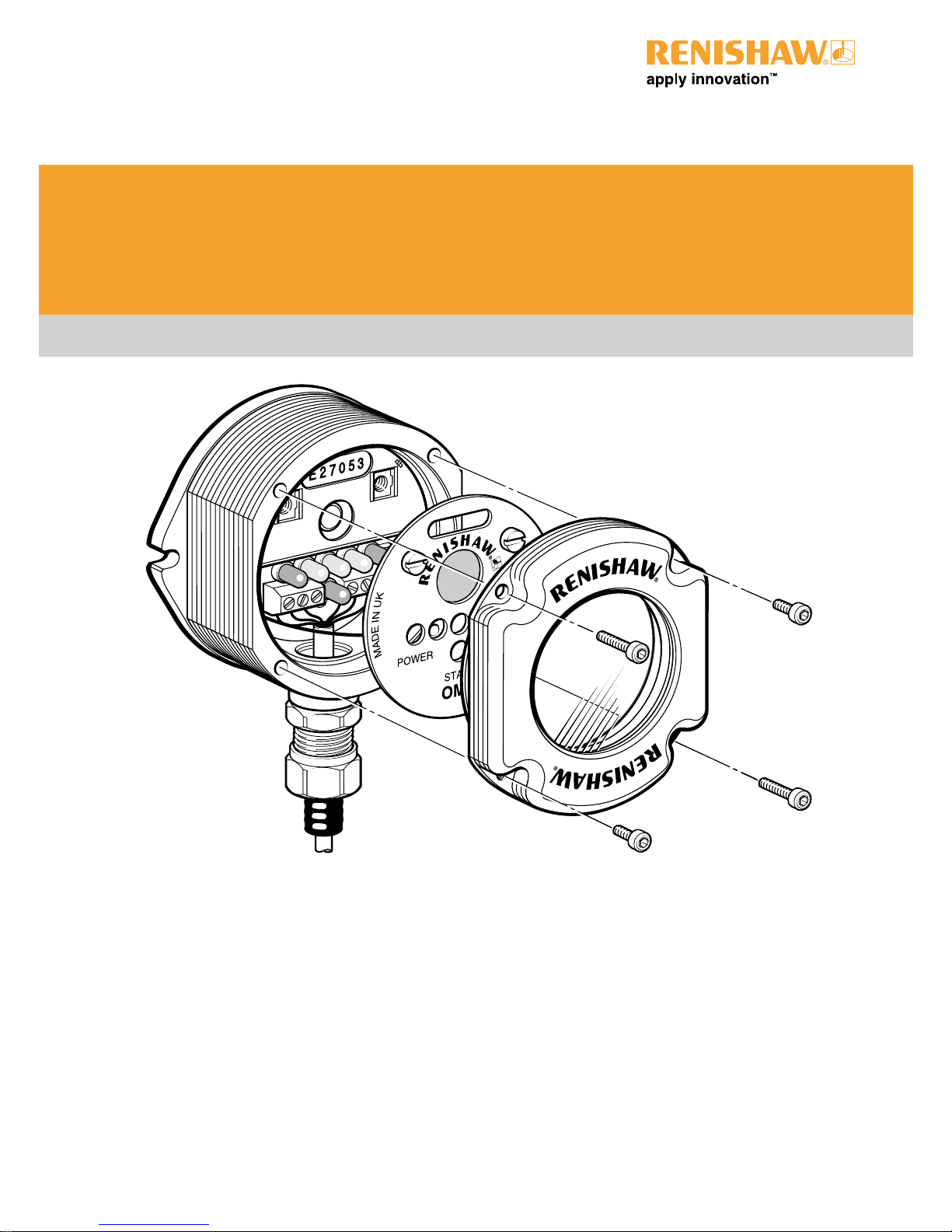
To remove the window and label from the OMM, carry out the following
(see Figure 1):
1. Using a 2.5 mm AF allen key, release and remove the two short
screws [1] and the two long screws [2] securing the window [3]
to the OMM body [4].
2. Re-insert the two long screws [2] into the two threaded holes A.
3. Tighten, in turn, the two long screws [2] to evenly and carefully
jack the window [3] from the OMM body [4]. Gently remove the
window from the OMM body.
4. Release the label [6] from the OMM body [4] by turning the
two quick release screws [5] a quarter turn counterclockwise.
Carefully lift the label from the OMM body to gain access to the
defective PCB.
!
 Loading...