

Page 1
H-2000-6199-02-A
2
1
R25=y
R26=z
R11=h
R25=y
=>?@D
NC1 non-contact
tool setting system
Programming Guide
(Siemens 810D / 840D and FMNC)
Page 2

© 2001 Renishaw. All rights reserved.
Renishaw® is a registered trademark of Renishaw plc.
This document may not be copied or reproduced in whole or in
part, or transferred to any other media or language, by any means
without the written prior permission of Renishaw.
The publication of material within this document does not imply
freedom from the patent rights of Renishaw plc.
Disclaimer
Considerable effort has been made to ensure that the contents of
this document are free from inaccuracies and omissions.
However, Renishaw makes no warranties with respect to the
contents of this document and specifically disclaims any implied
warranties. Renishaw reserves the right to make changes to this
document and to the product described herein without obligation
to notify any person of such changes.
Trademarks
All brand names and product names used in this document are
trade names, service marks, trademarks, or registered trademarks
of their respective owners.
Renishaw part no: H-2000-6199-02-A
Issued – February 2001
Page 3

NC1 non-contact
tool setting system
Programming Guide
(Siemens 810D / 840D and FMNC controls)
=>?@D
www.renishaw.com
Renishaw plc
New Mills, Wotton-under-Edge,
Gloucestershire, GL12 8JR, UK
Tel: +44 (0)1453 524524 [07000 RENISHAW]
Fax: +44 (0)1453 524901
email: uk@renishaw.com
1
Page 4

Cautions
Caution – Laser safety
The laser used in the Renishaw NC1 non-contact tool
setting system emits visible red light at a wavelength of
670nm and has a maximum power output of less than
1mW. It is a Class 2 product as defined by European and
American laser safety standards (EN60825-1:1994 and US Code of
Federal Regulations 21CFR1040).
When using the NC1 system:
n
Do not stare directly into the laser beam. The beam may be
viewed safely from the side.
n
Ensure that the laser beam is not reflected into the eyes of
another person via a mirror or other reflective surface.
n
Do not expose skin to the laser beam for longer than is absolutely
essential.
n
When the system is not being used, cover the laser beam
aperture with the sliding cover.
Caution – Software safety
The software you have purchased is used to control the
movements of a machine tool. It has been designed to
!
cause the machine to operate in a specified manner under
operator control, and has been configured for a particular
combination of machine tool hardware and controller.
Renishaw has no control over the exact program configuration of the
controller with which the software is to be used, nor of the
2
Page 5

Cautions
mechanical layout of the machine. Therefore, it is the responsibility of
the person putting the software into operation to:
n
ensure that all machine safety guards are in position and are
correctly working before commencement of operation;
n
ensure that any manual overrides are disabled before
commencement of operation;
n
verify that the program steps invoked by this software are
compatible with the controller for which they are intended;
n
ensure that any moves which the machine will be instructed to
make under program control would not cause the machine to
inflict damage upon itself or upon any person in the vicinity;
n
be thoroughly familiar with the machine tool and its controller and
know the location of all emergency stop switches.
Related publications
When using the Beam alignment cycle (subroutine L9860) you will
also need to refer to the following Renishaw publication. This contains
instructions on how to physically align the beam at the NC1
transmitter unit.
NC1 Installation Guide and Parts List
(Renishaw Part No. H-2000-5048)
3
Page 6

Contents
Contents
Renishaw NC1 tool setting system ..................................................... 6
Features of the NC1 system software ................................................ 7
Measuring subroutine features .................................................... 7
Calibration subroutine features .................................................... 7
Service subroutine features ......................................................... 8
Software memory requirements ......................................................... 9
Machine tool controllers supported .................................................... 9
Tool-offset types supported .............................................................. 10
Positive tool-offset applications.................................................. 10
Negative tool-offset applications ................................................ 10
Relative to a master tool with zero (0) tool-offset value. ........... 11
Measurement values used in this guide ........................................... 11
Installing the software ....................................................................... 12
Subroutine parameters ..................................................................... 12
Parameter store for calibration data ........................................... 12
Setting-data subroutine L9760 ................................................... 13
Common parameters ................................................................. 19
Customising the subroutines ............................................................ 20
Editing the measure move subroutine L9762 ............................ 20
Orientation of the NC1 system ......................................................... 21
Beam-find and measuring moves ..................................................... 22
Scatter tolerance checking ............................................................... 23
Beam alignment (subroutine L9860) ................................................ 24
Calibrating the NC1 (subroutine L9861) ........................................... 32
Tool length setting (subroutine L9862) ............................................. 38
4
Page 7

Contents
Tool radius/diameter setting (subroutine L9862) .............................. 43
Tool length and radius setting (subroutine L9862) ........................... 49
Cutting edge checking (subroutine L9862) ...................................... 55
Broken tool detection – plunge checking (subroutine L9863) .......... 60
Broken tool detection – radial checking (subroutine L9864) ............ 65
Cutter radius and linear profile checking (subroutine L9865) .......... 70
Temperature compensation tracking (subroutine L9861) ................. 79
Error messages and alarms ............................................................. 85
5
Page 8

Renishaw NC1 system
Renishaw NC1 tool setting system
This guide describes how to use the Renishaw NC1 non-contact tool
setting system software.
The Renishaw NC1 is a laser-based non-contact tool setting system
that provides high-speed/high-precision measurement of cutting tools
on a machining centre under normal operating conditions.
As a tool is moved through the laser beam, the system detects when
the beam is broken. Output signals sent to the controller allow the
presence of a tool and the position of the tip, a tooth, or a cutting
edge to be established.
The NC1 allows the following parameters to be established:
n
Length and diameter of the cutting tool. Tools as small as 0.2 mm
(0.008 in) diameter can be accurately measured.
n
Detection of a broken tool.
n
Detection of a broken tip or cutting edge, or excessive runout of a
tool.
n
Compensation for thermal changes in the machine tool.
6
Page 9

Software features
Features of the NC1 system software
NC1 system software provides the following measuring and
calibration features:
Measuring subroutine features
Four measuring subroutines provide the following features:
n
L9862 – used for measuring the length and diameter of the
cutting tool and for cutting edge checking.
n
L9863 – used for broken tool detection by plunge measurement.
This is intended for use on vertical machining centres.
n
L9864 – used for broken tool detection by radial measurement.
This is intended for use on horizontal machining centres.
n
L9865 – used for checking the radii and linear profile of the cutter.
Calibration subroutine features
Two calibration subroutines provide the following features:
n
L9860 – used for aligning the laser beam, setting the provisional
positions of the beam in the spindle and radial-measuring axes,
and setting the measuring position along the beam.
n
L9861 – used for calibrating the positions of the laser beam in the
spindle and radial-measuring axes, and for temperature
compensation of the spindle and radial-measuring axes.
7
Page 10

Software features
Service subroutine features
The measuring and calibration subroutines are supported by the
service subroutines listed below.
n
L9760 – used for the settings data.
n
L9761 – used for startup functions.
n
L9762 – used for the measuring routine.
n
L9763 – used for the G31 routine.
n
L9764 – used for the G0/G1 routine.
n
L9765 – used for the G2/G3 routine.
n
L9766 – used for the search routine.
n
L9769 – used for error messages.
n
L9800 – clears global ‘R’ parameters used for subroutine input
data.
NOTE: L9800 Clear global ‘R’ parameters.
The subroutine L9800 is called at the end of every measuring and
calibration subroutine (9800-series) to reset the global ‘R’
parameters, used as inputs, to a default value.
If global ‘R’ parameters R00 to R26 are used for other
programming purposes outside of this tool setting package, it is
recommended that L9800 is called prior to setting them for the
next tool setting routine. All examples in this programming guide
show this being done.
8
Page 11

Software memory requirements
Software memory requirements
NC1 system software requires approximately 28.0Kb (70 metres) of
part-program memory.
If your controller is short of memory, there is no need to load any of
the subroutines listed below if you do not intend using them:
n
L9862 (tool setting routine) 4.0 Kb (10 metres) of memory.
n
L9863 (broken tool – plunge check) 1.2 Kb (3 metres) of
memory.
n
L9864 (broken tool – radial check) 1 Kb (2.5 metres) of memory.
n
L9865 (checking cutter radii and linear profiles) 4.0 Kb
(10 metres) of memory.
You may also remove the following subroutine after you have finished
running the Beam alignment cycle:
n
L9860 (laser beam alignment routine) 1.5 Kb (3.8 metres) of
memory
Machine tool controllers supported
NC1 system software is suitable for use on the following machine tool
controllers:
n
Siemens 810D
n
Siemens 840D
n
Siemens FMNC
9
Page 12

Tool-offset types supported
Tool-offset types supported
Positive tool-offset applications
The NC1 software is ideally suited to setting tools using positive tooloffset values that represent the physical length of the tool.
Throughout this programming guide, descriptions refer to positive
tool-offset applications.
The software can also be used in applications where negative tooloffset values are used or where all tool-offset values are entered as ±
values relative to a master tool. These applications are described
below.
Negative tool-offset applications
The offset value entered is the distance the tool tip must be moved
from the home position to reach the zero (0) position of the part
program (air-gap method), rather than the physical length of the tool.
Example
Home position, to the zero (0) position of the part
program = –1000 mm.
A master calibration tool of 150 mm is used (offset register
value = –850 mm).
The longest tool for the machine is 200 mm long.
The shortest tool for the machine is 50 mm long.
Parameters RENC[10] and RENC[11] must be set in the Setting-data
subroutine (L9760). Set them as follows:
10
Page 13

Tool-offset types supported
RENC[10] = –800.0 Maximum length tool
RENC[11]= –950.0 Minimum length tool
Relative to a master tool with zero (0) tooloffset value.
The master tool-offset register is set to zero (0) and all other tooloffset registers are set as ± values relative to the master tool.
Example
Home position, to the zero (0) position of the part
program = –1000 mm (but this is not important)
A master calibration tool of 150 mm is used (offset register
value = 0).
The longest tool for the machine is 200 mm long.
The shortest tool for the machine is 50 mm long.
Parameters RENC[10] and RENC[11] must be set in the Setting-data
subroutine (L9760). Set them as follows:
RENC[10] = 50.0 Maximum length tool
RENC[11] = -100.0 Minimum length tool
Measurement values used in this guide
Throughout this guide, metric units of measurement, i.e. millimetres,
are used in the examples. The equivalent imperial measurements, i.e.
inches, are shown in brackets.
11
Page 14

Installing the software
Installing the software
Before installing the NC1 software, read the guidelines contained in
the Readme file on the software floppy disk.
Subroutine parameters
The following parameters are used by the NC1 system software:
n
‘RENT’ global parameters – used for the calibration data and
settings data.
n
Global parameters RENC[0] to RENC[49] – used for the settings
data.
n
Local parameters RENL[1] to RENL[32] – used for locally defined
data.
n
Global parameters R01 to R26 – used for subroutine inputs.
Parameter store for calibration data
The following parameters are set automatically during the calibration
cycles.
RENT[20] Z-axis position of the beam, when measured from the
positive side of the beam.
RENT[21] (Reserved)
RENT[22] X or Y-axis position of the beam, when measured from
the negative side of the beam.
RENT[23] X or Y-axis position of the beam, when measured from
the positive side of the beam.
12
Page 15

Parameter store for calibration data
RENT[24] Position along the beam at which measurements are
made.
RENT[26] Spindle (length-measuring) axis temperature
compensation zero offset.
RENT[27] Radial-measuring axis temperature compensation zero
offset.
Setting-data subroutine L9760
Read the following parameter descriptions then edit subroutine L9760
as described.
RENC[5] False trigger retries.
If probe status checking is deactivated (see RENT[5]
parameter), the software defaults to one (1) retry.
Default: 1
RENC[6] Safe return position (in ‘machine’ co-ordinates).
RENC[7] The unit used for setting data in subroutine L9760.
1 = mm, 0.04 = inch
Default: 1 (mm)
RENC[9] Setting for tool offset type, either radius or diameter.
1 = Radius, 2 = Diameter
Default: 1
RENC[10] Maximum length of the tool. This defines the rapid
approach height of the spindle nose above the laser
beam.
13
Page 16

Setting-data subroutine
RENC[11] Minimum length of the tool. This defines the lowest
measuring height of the spindle nose above the laser
beam.
RENC[12] Maximum diameter of the tool. This value is dependent
on the machine tool.
RENC[13] Radial-measuring axis options.
1 = measure from positive side of the beam,
–1 = measure from negative side of the beam,
2 = measure from both sides of the beam.
Default: 2
RENC[14] Radial calibration options.
1 = measure from positive side of the beam,
–1 = measure from negative side of the beam,
2 = measure from both sides of the beam.
Default: 2.
RENC[15] Hardware signal pulse time.
The time that the trigger signal is held on. This is
hardware-dependent. The value is specified when the
NC1 system is ordered.
Check the status LED sequence on power up (for
details, see
RENC[17] Default overtravel distance and radial clearance.
Overtravel is the distance through the beam that the
tool is permitted to move before a BEAM NOT CUT
alarm is initiated.
Radial clearance is the distance between the tool and
“NC1 Installation Guide and Parts List
”).
14
Page 17

Setting-data subroutine
the beam when moving down the side of the beam.
Default: 5 mm (0.197 in)
RENC[18] Default measurement resolution (feedrate-per-rev.).
Typically 0.001 mm (0.0001 in) feed per revolution.
The larger the value, the less accurate measurements
will be.
Default: 0.002 mm (0.0001 in)
RENC[19] Default spindle speed.
Measurement cycles are optimised for a spindle speed
of 3150 rev/min.
Some tools, e.g. those that are unbalanced or large,
must be run at speeds less than 3150 rev/min. This is
the responsibility of the user. Use the R19= input to set
speed.
Measurement cycle times increase with slower speeds.
The minimum speed is 800 rev/min.
Default value: 3150 rev/min
RENC[21] Beam axis.
n
If the laser beam is parallel to the X-axis, select 1.
n
If the laser beam is parallel to the Y-axis, select 2.
n
If the laser beam is parallel to the Z-axis, select 3.
RENC[22] Axis used for radial measurement.
n
If the X-axis is to be used for radial measurement,
select 1.
n
If the Y-axis is to be used for radial measurement,
select 2.
15
Page 18

Setting-data subroutine
n
If the Z-axis is to be used for radial measurement,
select 3.
Default: 2
RENC[23] Axis used for length measurement, i.e. the spindle axis.
n
If the X-axis is to be used for length measurement,
select 1.
n
If the Y-axis is to be used for length measurement,
select 2.
n
If the Z-axis is to be used for length measurement,
select 3.
Default: 3
NOTE: RENC[23] must always define the spindle axis
and the direction in which the tool offset is applied. If
the spindle is in the negative direction, the value
entered must also be negative (–1 = –X axis, –2 = –Y
axis, –3 = –Z axis).
RENC[24] Scatter tolerance value.
For a description of this feature, see the figure in
“Scatter tolerance checking” on page 23.
Default: 0.010 mm (0.0004 in)
RENC[25] Tolerance value for tool runout or cutting edge.
Default: 0.025 mm (0.001 in)
RENC[26] Sample size for scatter.
The number of measurement samples to be taken.
The number of retry attempts is twice this value.
16
Page 19

Setting-data subroutine
For a description of this feature, see the figure in
“Scatter tolerance checking” on page 23.
Default: 3
RENC[27] Rapid traverse feedrate.
Default: 5000 mm/min
RENC[28] Select language.
1 = English, 2 = German, 3 = French, 4 = Italian
RENT[5] Number of the digital input for monitoring the probe
status signal. This can be used only if the machine tool
builder (MTB) has provided the input.
From Siemens 840D version 4 software or 810D
version 2 software, a Probe Status flag is available.
This is used as the default.
Default: 0 (Siemens Probe Status flag)
RENT[7] Measuring input used on I/O interface connector X121.
RENT[7] = 1 Configured for N/O input on MEPUS 0
RENT[7] = -1 Configured for N/C input on MEPUS 0
RENT[7] = 2 Configured for N/O input on MEPUS 1
RENT[7] = -2 Configured for N/C input on MEPUS 1
RENT[9] Tool management system in use.
RENT[9] = n, where ‘n’ is the location number, usually
1, in the tool buffer. This is decided by the MTB during
machine commissioning.
Default: 0 (i.e. disabled)
17
Page 20

Setting-data subroutine
RENT[28] M code number to disable the latch mode. If the latch
mode feature is not to be used, enter 9 to select M9
coolant off (or similar).
RENT[29] M code number to enable the latch mode. If the latch
mode feature is not to be used, enter 9 to select M9
coolant off (or similar).
Editing subroutine L9760
Before running the cycles, edit the settings data between block
numbers LN1 and LN2 .
First, enter the metric/inch units factor (1. or .04) in parameter
RENC[7]. Next, enter data in the other parameters using the same
units.
Sample of subroutine L9760
LN1:
RENC[5]=1; RETRIES
RENC[6]=-1.; SAFE RETURN POSITION
RENC[7]=1; UNITS FOR DATA 1MM .04INCH
RENC[9]=1; OFFSET-RADIUS 1/DIAMETER 2
RENC[10]=200.; MAX TOOL LENGTH (8.0 in)
RENC[11]=70.; MIN TOOL LENGTH (2.75 in)
RENC[12]=80.; MAX CUTTER DIAMETER (3.15 in)
RENC[13]=2; TL SET RADIUS MEAS DIR
RENC[14]=2; CALIB RADIUS MEAS DIR
RENC[15]=.10; NC1-DELAY IN SECS
RENC[17]=5.; DEFAULT OVERTRAVEL (0.197 in)
RENC[18]=.002; MEASURE RESOLUTION (0.0001 in)
18
Page 21

Setting-data subroutine
RENC[19]=3150; DEFAULT RPM
RENC[21]=1; BEAM AXIS
RENC[22]=2; RADIAL MEASURE AXIS
RENC[23]=3; SPINDLE AXIS
RENC[24]=.01; SCATTER TOL (0.0004 in)
RENC[25]=.025; RUN OUT/CUTTING-EDGE TOL (0.001 in)
RENC[26]=1; SAMPLE SCATTER SIZE
RENC[27]=5000; RAPID TRAVERSE
RENC[28]=1; LANGUAGE 1=GB 2=D 3=FR 4=IT
RENT[5]=0;DIGITAL INPUT NO
RENT[7]=1;MEASURE INPUT
RENT[9]=0;MAGAZINE NUMBER FOR TL MANAGEMENT
RENT[28]= ;DISABLE LATCH
RENT[29]= ;ENABLE LATCH
LN2:
Common parameters
The following parameters are loaded automatically each time a cycle
is run.
RENC[16] Active tool length.
RENC[29]
to Used for internal calculations
RENC[47]
RENC[48] Tolerance flag output
(1 = Out of tolerance, 0 = In tolerance)
RENC[49] Used for internal calculations
19
Page 22

Customising the subroutines
Customising the subroutines
In addition to the subroutine customising information described below,
further customising and installation information is included in the
Readme file supplied with the NC1 software.
Editing the measure move subroutine L9762
The back-off move distance can be adjusted for optimisation of the
cycles. The tool must retract out of the beam otherwise the ACTIVE
BEAM CUT alarm will result.
Sample of subroutine L9762
RENL[6]=1.5; EDIT BOF
20
Page 23
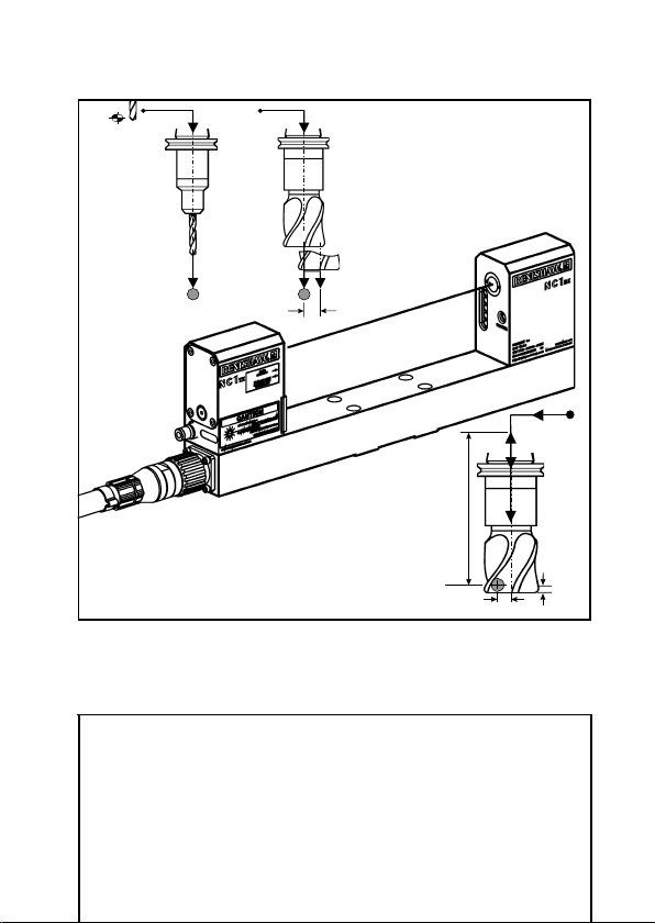
Orientation of the NC1 system
Orientation of the NC1 system
Throughout this guide it has been assumed that the NC1 system is
installed with the laser beam parallel to the X-axis. Length
measurements are made from the Z-axis and radial measurements
are made from the Y-axis.
If your system has been installed in a different orientation, you must
make the necessary adjustments to the axes used for length
measurement and radial measurement (for details, see manually-set
parameters RENC[21], RENC[22], and RENC[23].
Z
Y
X
X-axis beam
Z
Y
X
Z-axis beam (Special)
RENC[21] = 1
RENC[22] = 2
RENC[23] = 3
RENC[21] = 3
RENC[22] = 1
RENC[23] = 2
Y-axis beam
or
RENC[21] = 2
RENC[22] = 1
RENC[23] = 3
RENC[21] = 3
RENC[22] = 2
RENC[23] = 1
21
Page 24
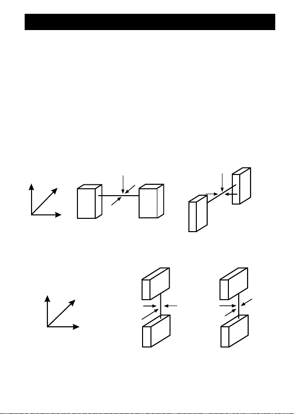
Beam-find and measuring moves
Beam-find and measuring moves
Beam-find moves and measuring moves are all made with the tool
moving into the laser beam, as shown in the figure. Measuring
moves are made with the tool rotating.
22
Fast
feed
Reduced
feed
Measure
feed
Sample
measurements
Page 25
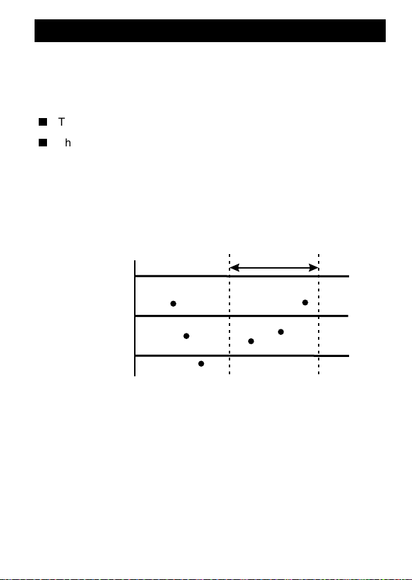
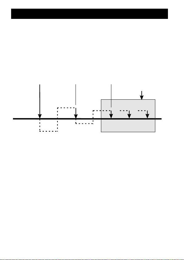
Scatter tolerance checking
Scatter tolerance checking
In the following example:
n
The default sample size setting value RENC[26] = 3 is used.
n
The number of retries is automatically set to twice the sample
size. In this example, six (6).
Sample measurements are taken until either the maximum retries
limit is reached, causing an alarm, or a sample of measurements is
found to be within limits. In this latter case, the average value is found
and measurement is complete.
Sample size
Maximum
Scatter
tolerance
Minimum
23
Page 26

Beam alignment
Beam alignment (subroutine L9860)
NOTE: When installing and setting up the system for the first time,
the Beam alignment subroutine must be run before using subroutine
L9861 to calibrate the system .
Subroutine L9860 is used during installation of the NC1 system to
assist with the alignment of the laser beam. The Beam alignment
cycle is used for the following tasks:
n
Checking that the beam is correctly aligned with the machine
axis.
n
Measuring the provisional position of the laser beam in the Zaxis.
n
Measuring the provisional position of the beam in either the X or
Y-axis. Measurements are taken from the positive and/or negative
sides of the beam.
n
Setting the measuring point along the beam axis at which the tool
is measured.
The provisional values are updated later when the calibration cycle is
run.
Although the Beam alignment subroutine is used mainly during
installation of the NC1 system, it can also be used for routine
24
Page 27
Beam alignment
Jog or
handwheel
to start point
R18=r (+/–)
R7=d
alignment checking.
NOTE: When using the Beam alignment subroutine you will also
need to refer to the following Renishaw publication for instructions on
how to physically align the beam at the transmitter unit:
n
NC1 Installation Guide and Parts List
(Renishaw Part No. H-2000-5048)
R18=r + R17=q
2
Calibration tool required
This cycle requires a calibration tool to be loaded in the spindle of the
machine. Ideally, this should be a solid, flat-bottomed, cylinder-type
tool having minimal runout. The exact setting length and diameter of
this tool must be known.
25
Page 28

Beam alignment
Description
Load the calibration tool in the spindle of the machine. Using either
the jog or handwheel mode, move the tool to the position that is to
be used for tool setting – usually midway along the beam and
approximately 10 mm (0.394 in) above the centre of the beam.
Refer to the figure on page 25. The cycle measures the beam then
returns to the centre position and stops on an M00 program stop.
After beam alignment adjustments have been made, the cycle should
be restarted to identify new alignment errors.
Setting data
Ensure the settings in subroutine L9760 are correct before
proceeding. For details, see “Setting-data subroutine L9760” on page
13.
Format
For beam alignment only
R07=d [R18=r R26=z].
L9860
where [ ] denotes optional inputs
Example R07=100. R18=6. R26=15.
L9860
For beam alignment and setting positions
R02=1. R07=d [R06=k R18=r R26=z]
L9860
26
Page 29

Examples R02=1. R07=100. R06=117. R26=15.
L9860
R02=1. R07=100. R26=15.
L9860
Subroutine inputs
The following inputs are used with this subroutine:
R02=1. Provisional calibration of the system.
Used for checking alignment of the beam and setting
the provisional beam positional data (for details, see
“Parameter store for calibration data” on page 12).
NOTE: When using the R02=1. input, the correct
length of the calibration tool MUST be entered in either
the appropriate tool offset register or as an R06=k
input. By default, the current tool offset length is used
or an alternative tool offset edge (D) can be called by
using the R20=t input).
R02=b (Not used) – beam alignment only.
Beam alignment
R06=k k= Reference length of the calibration tool.
27
Page 30

Beam alignment
CAUTION: R07=d input
When specifying the value of the R07=d input, take care
!
that it will not allow any part of the tool holder to make
contact with the NC1 tool setting system. The projection of the
calibration tool should be at least 35 mm (1.38 in) if the default R26=z
input is used for the incremental measuring depth.
R07=d d= The span between the reference measuring points.
For greatest accuracy, the span value must be as large
as possible, compatible with the gap between the NC1
system transmitter and receiver and the size of the
calibration tool.
R14=t t= Tool offset edge length value to be used in the beam
alignment calculations.
R14=3 Uses the current tool offset, edge D3.
If R14 is not input, the current tool offset edge (D) is
used. The current tool is the number of the tool in the
spindle.
If neither the R06=k nor R14=t input is used, the
current tool offset and tool edge (D) is used for
calibration data.
R17=q q= Overtravel distance and radial clearance.
For details, see “Setting-data subroutine L9760” on
page 13.
Default value: 5.0 mm (0.197 in)
28
Page 31

Beam alignment
Y+
X+
+ error
P2
P1
Y+
X+
+ error
P2
P1
R18=r r= Diameter of tool
This controls the radial clearance move distance. This
can be either a positive (+) or negative (–) value.
Default value: 30 mm (1.18 in)
R26=z z= Incremental measuring depth.
This value determines the depth on the calibration tool
at which calibration takes place.
Default value: 15 mm (0.38 in)
Outputs
The following outputs are set or updated when this cycle is executed:
RENC[1] X-axis beam alignment error
over the measured span.
(This is empty if the X-axis
is the beam axis.)
RENC[2] Y-axis beam alignment error
over the measured span.
(This is empty if the Y-axis is
the beam axis.)
29
Page 32

Beam alignment
Z+
X+
Y+
P2
P1
+ error
RENC[3] Z-axis beam alignment error
over the measured span.
(This is empty if the Z-axis is
the beam axis.)
If the R02=1 input is used, the following outputs are also set:
RENT[20] Provisional Z-axis position of the beam when measured
from the positive side of the beam.
RENT[22] Provisional X or Y-axis position of the beam when
measured from the positive side of the beam.
RENT[23] Provisional X or Y-axis position of the beam when
measured from the negative side of the beam.
RENT[24] Provisional position along the beam axis at which the
tool is measured.
(RENC[23] = 3)
30
Z
RENT[20]
RENT[23]
Y (RENC[22] = 2)
X (RENC[21] = 1)
RENT[22]
RENT[24]
Page 33

Beam alignment
Example
Beam alignment and setting the provisional beam
position
%_N_????
;R02=1 Include approximate set cal. data
;R07=d Axial distance between measures
;R18=r Tool diameter
;R26=z Search distance
T1
M6
D1
G0 G53 X302. Y-236.
M00 ; Handwheel to position
L9800
R02=1.R07=100. NOTE: Do not use the R02=1. input if you
want to keep the current calibration data.
M00
M30
31
Page 34

Calibrating the NC1
Calibrating the NC1 (subroutine L9861)
Subroutine L9861 is used for regular calibration of the NC1 system. It
should also be used after the laser beam has been aligned with the
Beam alignment cycle. The Calibration cycle is used for the following
tasks:
n
Accurately calibrating the positions of the beam in the X, Y and Zaxes.
n
Compensating for variations in the spindle axis and radialmeasuring axis due to temperature changes in the machine tool.
Temperature compensation is described in “Temperature
compensation tracking (subroutine L9861)” on page 79.
CAUTION: Before running this cycle or any other cycle
(except the Beam alignment subroutine L9860), nominal
!
calibration data must be loaded.
This data can be entered automatically using the Beam alignment
subroutine L9860, with the R02=1 input. Alternatively, approximate
data can be entered manually (for details, see “Parameter store for
calibration data” on page 12).
Calibration tool required
This cycle requires a calibration tool to be loaded in the spindle of the
machine and the tool number (T) must be active.
Ideally, this should be a solid, flat-bottomed, cylinder-type tool having
minimal runout. The exact setting length and diameter of this tool
must be known.
32
Page 35

Calibrating the NC1
R06=k
R19=s
1
2
R25=y
R17=q
3
R26=z
R18=r
R26=z
4
Description
Load the calibration tool in the spindle of the machine and make the
tool number (T) active before running the cycle.
The position of the beam in the Z-axis and the centre of the beam in
either the X or Y-axis are calibrated while the tool is rotated. The
beam width is then calibrated with the tool static. This eliminates
runout errors that may be introduced by the tool.
Refer to the figure above for cycle moves.
33
Page 36

Calibrating the NC1
Format R02=1. R18=r [R03=c R06=k R17=q R19=s R25=y
R26=z]
L9861
where [ ] denotes optional inputs
Example R02=1. R06=100.210 R18=12. R03=4. R17=5.
R19=2500. R25=5. R26=5.
L9861
Subroutine inputs
The following inputs are used with this subroutine:
R02=1. Calibration of the system.
R03=c c= Zero offset number used to track axis growth.
When used with the R02=b input, it stores the relevant
zero offset values as the reference position ready for
use later.
(See also “Temperature compensation tracking” on
page 79.)
R03=1 to R03=4 (G54 to G57)
R06=k k= Reference length of the calibration tool.
Default value: Value in the selected tool offset register
(which must be an exact known length).
R17=q q= Overtravel distance and radial clearance.
For details, see “Setting-data subroutine L9760” on
page 13.
Default value: 5.0 mm (0.197 in)
34
Page 37

Calibrating the NC1
R18=r r= Reference diameter of the calibration tool.
R19=s s= Spindle speed at which calibration takes place. For
details, see “Setting-data subroutine L9760” on page
13.
Default value: 3150 rev/min
R25=y y= Radial step-over for length calibration.
The offset across the beam at which measurement
takes place. The tool always comes down first on the
beam centre-line.
Default value: On-centre
R26=z z= Measuring height on tool.
Determines the height of the beam on the tool at which
diameter calibration takes place.
Default value: 5 mm (0.197 in)
Outputs
The following outputs are set or updated when this cycle is executed:
RENC[12] Temperature compensation error for length
measurement.
RENC[13] Temperature compensation error for radial
measurement.
RENT[20] Z-axis position of the beam, when measured from the
positive side of the beam.
RENT[22] X or Y-axis position of the beam, when measured from
the positive side of the beam.
35
Page 38

Calibrating the NC1
RENT[23] X or Y-axis position of the beam, when measured from
the negative side of the beam.
RENT[24] Position at which the beam is measured.
RENT[26] Spindle (length-measuring) axis temperature
compensation zero offset.
RENT[27] Radial-measuring axis temperature compensation zero
offset.
Alarms
The following alarms may be generated when this cycle is executed.
ACTIVE BEAM CUT
BEAM NOT CUT
FORMAT ERROR
OUT OF TOLERANCE
For an explanation of the meaning of alarms, see “Error messages
and alarms” on page 85.
Example
Calibration
Using a calibration tool T1, which is 88.0 mm (3.46 in) long and
6.0 mm (0.236 in) diameter.
%_N_????
T1
M6
D1
36
Page 39

Calibrating the NC1
L9800
R02=1.R06=88.R18=6.
L9861
M30
IMPORTANT: If you need to track the axis growth caused by
temperature variation during the machining operation, use the R03=c
input to store the relevant zero offset registers as reference values.
Example: R02=1. R06=88. R18=6. R03=1.
L9861
37
Page 40

Tool length setting
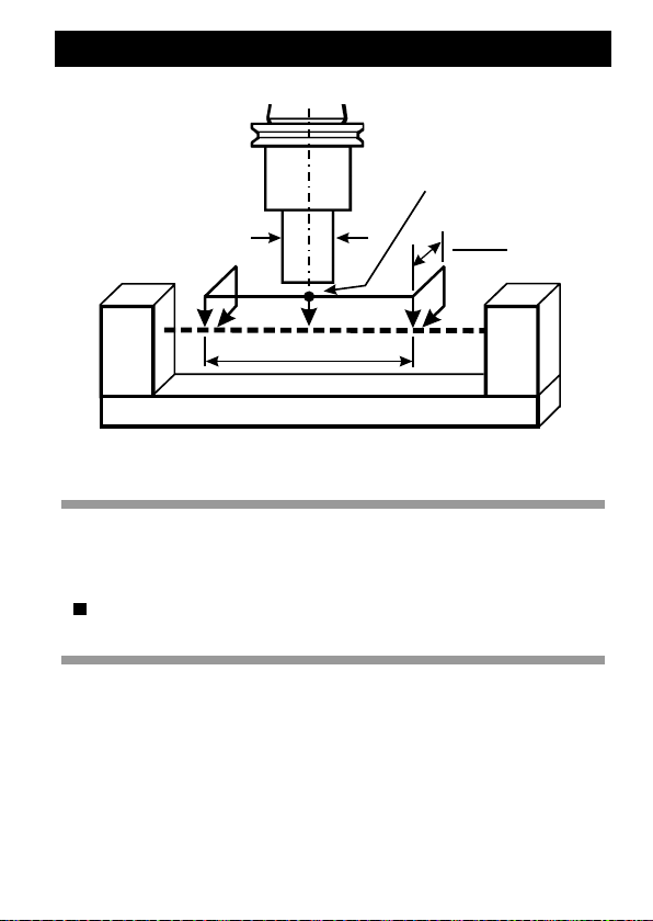
Tool length setting (subroutine L9862)
Subroutine L9862 is used to measure the effective length of a cutting
tool. The Tool length measurement cycle is suitable for on-centre
setting of tools such as drills and ball-end mills, and for off-centre
setting of tools such as face mills and end mills.
Description
Tool length is measured while the tool is rotating. The figure shows
the two cycle types.
Length setting
with no R25=y
input
38
1
Length setting
with R25=y
input
2
R25=y
Page 41

Tool length setting
The effective tool length is written to the current tool register and
nominated edge number (D). By default, the current tool number and
edge will be set.
Format [R02=1. R11=h R05=j R13=m R14=t R17=q R19=s
R25=y]
L9862
where [ ] denotes optional inputs
Example R02=1. R11=0.5 R05=0.25 R13=1. R14=2. R17=5.
R19=2500 R25=3.
L9862
Subroutine inputs
The following inputs are used with this subroutine:
R02=1. Set the length of the tool.
R02=1. is the default R02 input.
R05=j j= Experience value for length.
This value is the difference between the measured
length of the tool and the effective length when the tool
is under load during the cutting process. It is used to
refine the measured length, based on previous
experience of how the effective length differs from the
measured length when the tool is being used.
Default value: Not used.
R11=h h= Tolerance value that defines when the tool length is out
of tolerance.
When this input is used, the tool offset is not updated if
39
Page 42

Tool length setting
the tool length is found to be out of tolerance.
Default value: No tolerance check.
R13=1. Tool out of tolerance flag.
Using this flag prevents a tool OUT OF TOLERANCE
alarm from being raised.
R14=t t= Tool offset edge to be updated (usually up to nine
edges).
R14=3 Updates the current tool offset, edge D3.
If R14 is not input, the current tool offset edge (D) is
updated. The current tool is the number of the tool in
the spindle.
R17=q q= Overtravel distance.
For details, see “Setting-data subroutine L9760” on
page 13.
Default value: 5.0 mm (0.197 in)
R19=s s= Spindle speed at which length measurement takes
place. For details, see “Setting-data subroutine L9760”
on page 13.
Default value: 3150 rev/min
R25=y y= Radial step-over for length setting.
This is the offset across the beam at which length
measurement takes place. The value must be less than
the radius of the tool. The tool always comes down first
on the beam centre-line.
Default value: On-centre
40
Page 43

Tool length setting
Outputs
The following outputs are set or updated when this cycle is executed:
Set tool length
RENC[48] Out of tolerance flag. This is set when the measured
tool length is out of tolerance, provided the R11=h input
is used.
(1 = Out of tolerance, 0 = In tolerance)
Alarms
The following alarms may be generated when this cycle is executed.
FORMAT ERROR
OUT OF TOLERANCE
RPM OUT OF RANGE
For an explanation of the meaning of alarms, see “Error messages
and alarms” on page 85.
Examples
Tool length setting – on-centre tool
%_N_????
T1
M6
D1
L9800
R02=1. Set tool offset (1) on centre
41
Page 44

Tool length setting
L9862
M30
A different tool edge offset can be set by using the R14=t input on the
call line as follows:
R02=1.R14=2.R19=4000. Set tool offset edge D2 on centre.
L9862 Controlled rev/min.
Tool length setting – off-centre tool
Assume the tool is 80mm (3.15in) diameter.
%_N_????
T1
M6
L9800
R02=1.R25=38.R19=800. Set tool offset (1) at 38 mm (1.496 in)
radial step-over. Controlled rev/min.
L9862
M30
42
Page 45

Tool radius/diameter setting
Tool radius/diameter setting (subroutine
L9862)
Subroutine L9862 is used for measuring the effective radius/diameter
of a tool. The Tool radius measure cycle allows the radius/diameter to
be measured from the positive side of the beam, from the negative
side of the beam, or from both sides of the beam.
Description
The radius/diameter of a tool is measured while the tool is rotating.
The figure shows the cycle moves. Radial measurement (2) can be
1
2
R17=q
R18=r
R24=x
R26=z
43
Page 46

Tool radius/diameter setting
made on either one or both sides of the beam (see setting RENC[13]
in “Setting-data subroutine L9760” on page 13).
The effective radius/diameter is written into the tool offset register.
The wear register is zeroed and the radius/diameter value is placed in
the geometry register.
Format R02=2. [R11=h R04=i R13=m R14=t R17=q R18=r
R19=s R24=x R26=z]
L9862
where [ ] denotes optional inputs
Example R02=2. R11=0.5 R04=0.2 R13=1. R14=2. R17=5.
R18=25. R19=3000 R24=2. R26=6.
L9862
Subroutine inputs
The following inputs are used with this subroutine:
NOTE: If radial measurement at an exact height on the tool is
required, use the tool length and radius setting cycle (input R02=3).
This cycle automatically sets the length accurately before setting the
radius.
R02=2. Measure the radius of the tool.
R04=i i= Experience value for diameter or radius.
This value is the difference between the measured
diameter/radius of the tool and the actual diameter/
radius when the tool is under load during the cutting
process. It is used to define the measured diameter/
44
Page 47

Tool radius/diameter setting
radius, based on previous experience of how the
effective diameter/radius differs from the measured
diameter/radius when the tool is under load.
Default value: Not used.
NOTE: For cutter centre-line programming
applications, entering the nominal size as an
experience value will result in the error being stored
instead of the full radius/diameter of the cutter.
R11=h h= Tolerance value that defines when the tool diameter is
out of tolerance.
When this input is used, the tool offset is not updated if
the tool diameter is found to be out of tolerance.
Default value: No tolerance check.
R13=1. Tool out of tolerance flag.
Using this flag prevents a tool OUT OF TOLERANCE
alarm from being raised.
R14=t t= Tool offset edge to be updated (usually up to nine
edges).
R14=3 Updates the current tool offset, edge D3.
If R14 is not input, the current tool offset edge (D) is
updated. The current tool is the number of the tool in
the spindle.
45
Page 48

Tool radius/diameter setting
R17=q q= Overtravel distance and radial clearance.
For details, see “Setting-data subroutine L9760” on
page 13.
Default value: 5.0 mm (0.197 in)
R18=r r= Diameter of tool.
This is the nominal diameter of the tool.
Default value: Maximum diameter of tool in
RENC[12].
R19=s s= Spindle speed at which diameter measurement takes
place. For details, see “Setting-data subroutine L9760”
on page 13.
Default value: 3150 rev/min
R24=x x= Spindle axis search distance.
This defines a search distance above the R26=z input
measuring height, which can be used to find a radial
high spot on the cutter. It is suitable for single-point
boring bars and cutters with irregular radial profiles.
Cycle time is increased using this input.
Default value: Zero (0)
R26=z z= Measuring height of tool.
This is the Z-axis position from the end face of the tool
at which measurement takes place.
Default value: 5.0 mm (0.197 in)
46
Page 49

Tool radius/diameter setting
Outputs
The following outputs are set or updated when this cycle is executed:
Set tool radius/diameter
RENC[48] Out of tolerance flag. This is set when the measured
tool length is out of tolerance, provided the R11=h input
is used.
(1 = Out of tolerance, 0 = In tolerance)
Alarms
The following alarms may be generated when this cycle is executed.
FORMAT ERROR
OUT OF TOLERANCE
RPM OUT OF RANGE
For an explanation of the meaning of alarms, see “Error messages
and alarms” on page 85.
Examples
Tool radius setting 1
Assume the tool is a 10 mm (0.394 in) diameter slot drill.
%_N_????
T1
M6
L9800
47
Page 50

Tool radius/diameter setting
R03=2.R14=2. Inputs to set tool radius edge D2.
L9862
M30
Tool radius setting 2
Assume the tool is an 80 mm (3.15 in) diameter cutter.
%_N_????
T2
M6
L9800
R03=2.R19=800.R18=80. Inputs to set current tool radius
edge (default). Controlled rev/min and
radial clearance.
L9862
M30
48
Page 51

Tool length and radius setting
Tool length and radius setting (subroutine
L9862)
Subroutine L9862 is used for measuring the effective length and
radius/diameter of a tool. The Tool length and radius measure cycle is
particularly suitable for tools such as face mills, end mills, slot cutters,
disc mill cutters, dovetail cutters and boring tools.
1
2
R25=y
R17=q
3
R18=r
R24=x
R26=z
49
Page 52

Tool length and radius setting
Description
This single cycle combines the Tool length measuring cycle (see “Tool
length setting” on page 38) and Tool radius/diameter measuring cycle
(see “Tool radius/diameter setting” on page 43).
The figure shows the combined cycle moves. Radial measurement (3)
can be made on either one or both sides of the beam (see setting
RENC[13] in “Setting-data subroutine L9760” on page 13).
Length and radius values are written into the tool offset register. The
wear registers are zeroed and the values are placed in the geometry
registers.
Format R02=3. [R11=h R04=i R05=j R13=m R14=t R17=q
R18=r R19=s R24=x R25=y R26=z]
L9862
where [ ] denotes optional inputs
Example R02=3. R11=0.2 R04=0.2 R05=0.025 R13=1. R14=2.
R17=5. R18=25. R19=2500 R24=2. R25=3. R26=6.
L9862
Subroutine inputs
The following inputs are used with this subroutine:
R02=3. Measure the length and radius of the tool.
R04=i i= Experience value for diameter or radius.
This value is the difference between the measured
diameter/radius of the tool and the actual diameter/
radius when the tool is under load during the cutting
50
Page 53

Tool length and radius setting
process. It is used to define the measured diameter/
radius, based on previous experience of how the
effective diameter/radius differs from the measured
diameter/radius when the tool is under load.
Default value: Not used.
NOTE: For cutter centre-line programming
applications, entering the nominal size as an
experience value will result in the error being stored
instead of the full radius/diameter of the cutter.
R05=j j= Experience value for length.
This value is the difference between the measured
length of the tool and the actual length when the tool is
under load during the cutting process. It is used to
refine the measured length, based on previous
experience of how the effective length differs from the
measured length when the tool is under load.
Default value: Not used.
R11=h h= Tolerance value that defines when the tool is out of
tolerance.
When this input is used, the tool offset is not updated if
the tool is found to be out of tolerance.
Default value: No tolerance check.
R13=1. Tool out of tolerance flag.
Using this flag prevents a tool OUT OF TOLERANCE
alarm from being raised.
51
Page 54

Tool length and radius setting
R14=t t= Tool offset edge to be updated (usually up to nine
edges).
R14=3 Updates the current tool offset, edge D3.
If R14 is not input, the current tool offset edge (D) is
updated. The current tool is the number of the tool in
the spindle.
R17=q q= Overtravel distance and radial clearance.
For details, see “Setting-data subroutine L9760” on
page 13.
Default value: 5.0 mm (0.197 in)
R18=r r= Diameter of tool.
This is the nominal diameter of the tool.
Default value: Maximum diameter of tool in
RENC[12].
R19=s s= Spindle speed at which length and diameter
measurement takes place. For details, see “Settingdata subroutine L9760” on page 13.
Default value: 3150 rev/min
R24=x x= Spindle axis search distance.
This defines a search distance above the R26=z input
measuring height, which can be used to find a radial
high spot on the cutter. It is suitable for single-point
boring bars and cutters with irregular radial profiles.
Cycle time is increased using this input.
Default value: Zero (0)
52
Page 55

Tool length and radius setting
R25=y y= Radial step-over for length setting.
This is the offset across the beam at which length
measurement takes place. The value must be less than
the radius of the tool. The tool always comes down first
on the beam centre-line.
Default value: On-centre
R26=z z= Measuring height of tool.
This is the Z-axis position from the end face of the tool
at which measurement takes place.
Default value: 5.0 mm (0.197 in)
Outputs
The following outputs are set or updated when this cycle is executed:
Set tool length
Set tool radius/diameter
RENC[48] Out of tolerance flag. This is set when the measured
tool length is out of tolerance, provided the R11=h input
is used.
(1 = Out of tolerance, 0 = In tolerance)
Alarms
The following alarms may be generated when this cycle is executed.
FORMAT ERROR
OUT OF TOLERANCE
RPM OUT OF RANGE
53
Page 56

Tool length and radius setting
For an explanation of the meaning of alarms, see “Error messages
and alarms” on page 85.
Examples
Tool length/radius setting 1
Assume the tool is a 10 mm (0.394 in) diameter slot drill.
%_N_????
T1
M6
D1
L9800
R03=3.R14=2. Inputs to set tool length/radius edge D2.
L9862
M30
Tool length/radius setting 2
Assume the tool is an 80 mm (3.15 in) diameter cutter.
%_N_????
T1
M6
D1
L9800
R03=3.R14=2. Inputs to set current tool length at 38 mm
R25=38.R19=800. (1.496 in) radial step-over and radial offset
edge D2. Controlled rev/min.
L9862
M30
54
Page 57

Cutting edge checking
Cutting edge checking (subroutine L9862)
NOTE: This cycle can be used only if the latch mode feature of the
NC1 system is installed and operational.
Subroutine L9862 is used for checking the cutting edges of a tool.
The diameter Cutting edge check cycle checks for either missing or
damaged teeth or for excessive runout of the cutter.
1
2
R25=y
R17=q
3
R18=r
R24=x
R26=z
4
R06=k
55
Page 58

Cutting edge checking
Description
Before a tool is checked for missing teeth or excessive runout, it is
first set for radius/diameter. The diameter Cutting edge check cycle
then moves the rotating tool into the beam until the teeth interfere
with the beam by the cutting edge runout tolerance value. This value
is defined by the R06=k input.
The spindle speed is calculated from the minimum pulse signal delay
RENC[15] of the NC1 system and the number of teeth on the cutting
tool. This ensures that when each tooth enters the beam, a
permanent beam cut signal is held unless a tooth is either missing or
is out of tolerance. The beam cut signal is monitored for a minimum of
two revolutions.
Format R02=2. or R02=3. R03=c [R06=k R13=m R17=q R18=r
R19=s R26=z R24=x R09=f]
L9862
where [ ] denotes optional inputs
Example R02=2. or R02=3. R03=6. R06=0.02 R13=1. R17=5.
R18=25. R19=2500 R26=6. R24=5. R09=0.1
L9862
Subroutine inputs
The following inputs are used with this subroutine:
R02=2. For details of these cycles, see either “Tool radius/
R02=3. diameter setting” on page 43 or “Tool length and radius
setting” on page 49.
R02=4. Cutting edge check without tool offset updating.
56
Page 59

Cutting edge checking
R03=c c= The number of teeth on the tool. This automatically
selects the cutting edge check.
Default value: No default.
R06=k k= The tolerance value that defines when the tool cutting
edge runout is excessive.
Default value: 0.025 mm (0.0098 in)
R09=f f= Feedrate-per-rev. for cylinder profile checking when
using the R24=x input.
Default value: 0.1 mm (0.0394 in)
R13=1. Tool out of tolerance flag.
Using this flag prevents a tool OUT OF TOLERANCE
alarm from being raised.
R17=q q= Overtravel distance and radial clearance.
For details, see “Setting-data subroutine L9760” on
page 13.
Default value: 5.0 mm (0.197 in)
R18=r r= Nominal diameter of the tool.
Default value: Maximum diameter of tool in
RENC[12].
R19=s s= Spindle speed at which radius/diameter measurement
takes place. For details, see “Setting-data subroutine
L9760” on page 13.
The spindle speed for cutting edge checking is set
automatically and is based on the minimum pulse
57
Page 60

Cutting edge checking
signal delay of the control and the number of teeth on
the tool.
Default value: 3150 rev/min.
R24=x x= Cylinder profile checking distance, i.e. the spindle axis
movement, while edge checking. The value is
incremental from the R26=z input radial measuring
position. It is used in conjunction with the R09=f input
feed rate.
Default value: Zero (0)
R26=z z= Measuring height of tool.
This is the Z-axis position from the end face of the tool
at which measurement takes place.
Default value: 5.0 mm (0.197 in)
Outputs
The following output is set or updated when this cycle is executed:
RENC[48] Out of tolerance / Missing edge flag.
This is set when either the tool cutting edge runout is
out of tolerance, provided the R06=k input is used, or
an edge is missing from the tool.
(2 = Out of tolerance / edge missing
0 = In tolerance / no edges missing)
Alarms
The following alarms may be generated when this cycle is executed.
ACTIVE BEAM CUT
58
Page 61

Cutting edge checking
FORMAT ERROR
OUT OF TOLERANCE
RPM OUT OF RANGE
RUN-OUT/EDGE MISSING
For an explanation of the meaning of alarms, see “Error messages
and alarms” on page 85.
Examples
Cutting edge checking
Assume a 2-flute slot drill and check for a broken edge 0.5 mm from
the end face of the cutter.
%_N_????
T1
M6
D1
L9800
R02=2.R03=2.R26=0.5
L9862
Cylinder cutting edge checking
%_N_????
T1
M6
D1
L9800
R02=3.R03=2.R26=0.5R24=5.0
L9862
59
Page 62

Broken tool detection (plunge check)
Broken tool detection – plunge checking
(subroutine L9863)
Subroutine L9863 is used to check for breakage of cutting tools. The
Broken tool cycle uses a plunge check, where the tool is moved into
and out of the laser beam in the axis used for length setting. The
cycle can also check for a ‘long tool’ condition, where the tool has
possibly pulled out during machining.
Typically, a tool needs to be checked after a machining operation to
verify that it is not broken before the next tool is selected.
R26=z
60
R11=h
R25=y
Page 63

Broken tool detection (plunge check)
Description
Detection of a broken tool occurs while the tool is rotated in the
beam. Moves into and out of the beam are at the rapid feedrate.
The tool first moves over the beam, in the X and Y axes, to the
measuring position and then moves, in Z, to the tool checking
position.
When a positive R11=h input is used, the tool is checked at the
broken tool position only. When a negative R11=h input is used, the
tool is checked at both the long tool and broken tool positions.
At the end of the cycle, the tool moves out of the beam to the safe
position in the spindle axis only.
Format [R11=h R13=m R19=s R25=y R26=z]
L9863
where [ ] denotes optional inputs
Example R11=5. R13=1. R19=2800. R25=3. R26=6.
L9863
Subroutine inputs
The following inputs are used with this subroutine:
R11=h h= Tolerance value that defines when the tool is defined as
broken. A negative value (R11= –) checks the tool for
both broken and long tool conditions.
Default value: 0.5 mm (0.0197 in).
61
Page 64

Broken tool detection (plunge check)
R13=1. Tool broken flag.
Using this flag prevents a BROKEN TOOL or OUT OF
TOLERANCE alarm from being raised.
R19=s s= Spindle speed at which checking for a broken tool takes
place. For details, see “Setting-data subroutine L9760”
on page 13.
Default value: 3150 rev/min.
R25=y y= Radial step-over distance.
The offset across the beam at which measurement of
the tool length takes place.
Default value: On-centre
R26=z z= Safety plane.
The distance (in the spindle axis) to which the tool is
retracted.
Default value: No retract
Outputs
The following output is always set when this cycle is executed:
RENC[48] Broken tool flag.
(2 = long tool, 1 = broken tool, 0 = good tool)
62
Page 65

Broken tool detection (plunge check)
Alarms
The following alarms may be generated when this cycle is executed.
BROKEN TOOL
FORMAT ERROR
RPM OUT OF RANGE
For an explanation of the meaning of alarms, see “Error messages
and alarms” on page 85.
Example
Broken tool detection – plunge check
%_N_????
T1
M6
D1
G0Z200. Move to a safe position where the broken tool
cycle can be called.
X200.Y300.
L9800
R26=100. Make a broken tool check. Either a broken
L9863 tool alarm is raised and the program stops, or
the program continues.
T2 Select the next tool and continue.
M6
(continue machining)
63
Page 66

Broken tool detection (plunge check)
If the broken tool flag method is used, the call cycle is modified as
follows:
L9800
R26=100.R13=1. Make a broken tool check without raising an
alarm.
The RENC[48] flag is set.
L9863
IF RENC[48]==1 GOTOF LN100 Go to LN100
(continue program)
Block LN100 will contain corrective actions. For example, selecting a
sister tool for use, or selecting a new pallet/component.
64
Page 67

Broken tool detection (radial check)
Broken tool detection – radial checking
(subroutine L9864)
Subroutine L9864 is used to check for breakage of cutting tools. The
Broken tool cycle uses a radial check, where the tool is moved
through the laser beam in the direction used for radius/diameter
setting.
Typically, a tool needs to be checked after a machining operation to
verify that it is not broken before the next tool is selected.
Description
Detection of a broken tool occurs while the tool is rotated in the
beam. Moves through the beam are at the rapid feedrate.
R25=y
R26=z
R11=h
65
Page 68

Broken tool detection (radial check)
The cycle rapids the tool to the measuring height at a depth defined
by the broken tool tolerance value (R11=h input) The tool then moves
in rapid through the beam and is monitored for a broken tool
condition, i.e. the beam is not cut. The radial distance moved by the
tool from the beam centre-line is defined by the R25=y input.
At the end of the cycle, the tool moves out of the beam to the safe
position in the spindle axis only.
CAUTION
!
installed and operational if the R25=y input is to be used when
passing the tool through the beam.
2. Before this cycle is called, the tool must be moved to a safe, clear
position in the Z, X, and Y axes. Ensure that the position along the
beam axis to which the tool is moved is safe for radial checking.
1. The latch mode feature of the NC1 system must be
Format [R11=h R13=m R19=s R25=y R26=z]
L9864
where [ ] denotes optional inputs
Example R11=5. R13=1. R19=2800 R25=3. R26=6.
L9864
66
Page 69

Broken tool detection (radial check)
Subroutine inputs
The following inputs may be required for this subroutine:
R11=h h= Tolerance value that defines when the tool is defined as
broken.
Default value: 0.5 mm (0.0197 in).
R13=1. Tool broken flag.
Using this flag prevents a BROKEN TOOL alarm from
being raised.
R19=s s= Spindle speed at which checking for a broken tool takes
place. For details, see “Setting-data subroutine L9760”
on page 13.
Default value: 3150 rev/min.
R25=y y= Monitoring distance past the beam centre-line.
Use a Y– (negative) value for a negative axis move.
Default value: On-centre
R26=z z= Safety plane.
The distance (in the Z-axis) to which the tool is
retracted.
Default value: No retract
Outputs
The following output is always set when this cycle is executed:
RENC[48] Broken tool flag.
(1 = broken tool, 0 = good tool)
67
Page 70

Broken tool detection (radial check)
Alarms
The following alarm may be generated when this cycle is executed.
BROKEN TOOL
For an explanation of the meaning of alarms, see “Error messages
and alarms” on page 85.
Example
Broken tool detection – radial check
%_N_????
T1
M6
D1
G0Z200.
(complete the machining sequence with tool T1)
G0Z200. Move to a safe position in the Z-axis
where the broken tool cycle can be
called.
X200.Y300. Move to a safe position in the X and Y
axes where the broken tool cycle can
be called.
L9800
R25=50.R26=100. Make a broken tool check. Either a
L9864 BROKEN TOOL alarm is raised and
the program stops, or the program
continues.
68
Page 71

Broken tool detection (radial check)
T2
M6 Select the next tool and continue.
(continue machining)
If the broken tool flag method is used, the call cycle is modified as
shown:
L9800
R25=50.R26=100.R13=1. Make a broken tool check
L9864 without raising an alarm.
The RENC[48] flag is set.
IF RENC[48]==1 GOTOF LN100 Go to LN100
(continue program)
Block LN100 will contain corrective actions. For example, selecting a
sister tool for use, or select a new pallet/component.
69
Page 72

Cutter radius and linear profile checking
Cutter radius and linear profile checking
(subroutine L9865)
NOTE: This cycle can be used only if the latch mode feature of the
NC1 system is installed and operational.
This cycle is used to check the profile of ballnose cutters, cutters with
corner radii, and cutters with linear profiles. The profile is checked to
find out if it is within a specified form tolerance.
Application
The tool is retracted to the home position for safety before each
profile check unless a secondary profile check is to be performed on
the same tool (see use of inputs R02=4, R02=5, and R02=6). The
tool is positioned over the laser beam and is moved first to the
longest tool position, then to the profile start position with the spindle
rotating. The defined cutter profile is traced at the checking feedrate.
Finally, the tool is retracted out of the beam. An error flag is always
set and an alarm is optionally generated if the cutter is out of
tolerance.
If both + and – tolerance checking is specified with the R02=3 and
R02=6 inputs, the cutter is repositioned after the negative (–)
tolerance check and a reverse profile check is made along the profile.
Finally, the tool is retracted.
70
Page 73

Cutter radius and linear profile checking
With R18=r input
R11=h
R25=y
–Tol.
R06=k
R18=r
R05=j
R17=q
Checking a
linear profile
Format
For radius profile checking
R18=r R24=x [R02=b R03=c R09=f R11=h R05=j
R06=k R13=m R14=t R17=q R19=s R25=y R26=z]
L9865
where [ ] denotes optional inputs
+Tol.
R24=x
No R18=r input
R06=k
R25=y
Checking a profile
with corner radius
–Tol.
+Tol.
R17=q
R24=x
R11=h
71
Page 74

Cutter radius and linear profile checking
Example R18=10. R24=5. R02=3. R03=4. R09=0.3 R11=1.
R05=1. R06=1. R13=1 R14=2. R17=90. R19=4000.
R25=5. R26=50.
L9865
For linear profile checking
R24=x [R02=b R03=c R09=f R11=h R06=k R13=m
R14=t R17=q R19=s R25=y R26=z]
L9865
where [ ] denotes optional inputs
Example R24=5. R02=1. R03=4. R09=0.3 R11=.5 R06=1.
R13=1 R14=2. R17=90. R19=4000. R25=5. R26=50.
L9865
Subroutine inputs
R02=1. Check the cutter profile along the negative (–) tolerance
profile limit (see the figures on page 71).
R02=2. Check the cutter profile along the positive (+) tolerance
profile limit (see the figures on page 71).
R02=3. Combine both R02=1. and R02=2. profile checking in
one operation. This is the default if the R02= input is
not used.
R02=4. These are the same as the R02=1., R02=2., and
R02=5. R02=3. inputs respectively, except that the tool does
R02=6. not retract first. These cycles are suitable for performing
secondary profile checks on the same tool.
72
Page 75

Cutter radius and linear profile checking
TIP: To prevent retracting at the end of the cycle, use
an R26=0 input.
R03=c c= When this input is used, enter the number of cutting
edges on the tool. The spindle speed is then
automatically adjusted to enable errors on each cutting
edge to be checked.
The cycle time using this method is significantly
increased, unless the default 0.1 mm/rev (0.004 in/rev)
is increased using the R09=f input.
Default value: The spindle speed is set by either the
R19=s input, or by the default value defined in the
setting subroutine L9760 when no R19=s input is used.
R03=1. The spindle speed is automatically adjusted for a cutter
with a single cutting-edge to ensure it is properly
checked.
This is also suitable for multiple-tooth cutters, when
only the maximum/minimum cutting-edge profile needs
to be checked. The cycle time will be faster than
checking each individual cutting edge.
R06=k k= The tolerance value that defines when the cutter profile
is out of limits.
Default value: 0.025 mm (0.001 in)
R09=f f= Feedrate specified as feed/rev for profile checking.
Default value: 0.1 mm/rev (0.004 in/rev)
73
Page 76

Cutter radius and linear profile checking
R13=1. Used to prevent an alarm being raised when the profile
is out of limits.
R14=t t= Tool length offset edge.
This is the offset location in which the measured tool
length is stored.
Default value: Current tool edge.
R19=s s= The spindle speed for the cutter.
This value is used for profile checking when no R03=c
input is used; otherwise, the spindle speed is adjusted
automatically for profile checking.
Default value: 3150 rev/min.
R26=z z= Retract distance after profile checking.
The tool reference point is retracted to this position.
Default value: Retract to the home position
Additional subroutine inputs for radius profile checking
only
R05=j j= Start position adjustment relative to the cutter radius
centre for profile checking (see the figures on page 71).
Range: radial ³ 0 <R18=r input
R11=h h= The height from the tool length offset position to the
bottom of the radius profile, i.e. the J0 position (see the
figures on page 71).
Range: ³ 0
Default value: R06=k value.
74
Page 77

Cutter radius and linear profile checking
R17=q q= Included angle of the cutter radius.
Range: ³ 0° £ 90°
R18=r r= The cutter radius value.
R24=x x= Linear distance moved tangentially past the cutter
radius profile (see the figures on page 71).
Range: ³ 0
R25=y y= Radial distance to the cutter radius centre.
Range: ³ 0
Additional subroutine inputs for linear profile checking
only
R11=h h= The height to the first profile checking position (see the
figures on page 71).
This is the height above the tool length offset position.
Range: ³ 0
Default value: R06=k value.
R17=q q= Angle of the linear profile (see the figures on page 71).
Range: ³ 0° £ 90°
R24=x x= Distance along the surface for profile checking (see the
figures on page 71).
Range: ³ 0
R25=y y= Radial position to the first profile checking position.
Range: ³ 0
75
Page 78

Cutter radius and linear profile checking
Outputs
NOTE: When the R02=3. or R02=6. input is used and the tool is
found to be out of tolerance during the negative (–) tolerance profile
check, the cycle is automatically aborted and does not complete the
positive (+) tolerance profile check.
RENC[48]=0 The profile is in tolerance
RENC[48]=1 The profile is out of tolerance during negative (–)
tolerance profile checking
RENC[48]=2 The profile is out of tolerance during positive (+)
tolerance profile checking
Alarms
The following alarms may be generated when this cycle is executed.
FORMAT ERROR
RPM OUT OF RANGE
RUN-OUT/EDGE MISSING
TOOL OUT OF RANGE
For an explanation of the meaning of alarms, see “Error messages
and alarms” on page 85.
76
Page 79

Cutter radius and linear profile checking
Examples
Profile checking a Ø20 mm (0.787 in) ballnose cutter
Check the profile is within ±0.05 mm (0.002 in)
The profile checking starts at 1 mm (0.040 in) radial from the cutter
centre and then moves around the 90° radius, and then a further
15 mm (0.591 in) up the diameter of the tool
%_N_????
T1
M6
D1
L9800
R18=10.R24=15.R05=1.R06=.05
L9865
M30
77
Page 80

Cutter radius and linear profile checking
Profile checking a Ø20 mm (0.787 in) tapered cutter with
10° side taper
Check the profile is within ±0.05 mm (0.002 in).
The profile check starts at 1 mm (0.040 in) high and 10.176 mm
(0.401 in) radial, and then moves along the taper for 30 mm
(1.181 in).
%_N_????
T1
M6
D1
L9800
R11=1.R06=.05R17=80.R24=30.R25=10.176
L9865
M30
78
Page 81

Temperature compensation tracking
Temperature compensation tracking
(subroutine L9861)
Subroutine L9861 can be used to calibrate the NC1 system for
variations in the spindle axis and/or the radial-measuring axis caused
by temperature changes in the machine tool.
Run this cycle on a regular basis during machining operations to
compensate for growth in the spindle axis and/or radial-measuring
axis.
1
2
R25=y
R17=q
3
R18=r
79
Page 82

Temperature compensation tracking
Description
The calibration tool must be loaded in the spindle of the machine.
Refer to the figure showing cycle moves.
The subroutine is used as described previously in “Calibrating the
NC1 (subroutine L9861)” on page 32, but instead of resetting the
calibration data, the beam positions are compared with the original
calibration values. The deviation for each axis is then used to adjust
the relevant zero offset.
NOTE: It is important to use the same calibration tool and input
values that were previously used for calibration, except that input
R02=4., R02=5. or R02=6. is now used.
After the original reference values have been stored, independent
adjustments to the zero offset values are ignored and overwritten by
the temperature tracking cycle.
Format
For full temperature compensation
R02=6. R03=c R06=k R18=r [R17=q R19=s R25=y]
L9861
where [ ] denotes optional inputs
Example R02=6. R03=3. R06=88. R18=6. R17=5. R19=2500
R25=5.
L9861
80
Page 83

Temperature compensation tracking
For spindle axis temperature compensation
R02=4. R03=c R06=k [R17=q R19=s R25=y]
L9861
where [ ] denotes optional inputs
Example R02=4. R03=3. R06=88. R17=5. R19=2500 R25=5.
L9861
For radial measuring axis temperature compensation
R02=5. R03=c R18=r [R17=q R19=s]
L9861
where [ ] denotes optional inputs
Example R02=5. R03=3. R18=6. R17=5. R19=2500.
L9861
Subroutine inputs
The following inputs are used with this subroutine:
R02=4. Temperature compensation tracking in the spindle axis.
This performs a beam find and length measurement in
the spindle axis only.
R02=5. Temperature compensation tracking in the radial-
measuring axis. This performs a beam find and radial
measurement only.
R02=6. Temperature compensation tracking in both the spindle
axis and radial-measuring axis. This performs both
operations described for inputs R02=4. and R02=5.
81
Page 84

Temperature compensation tracking
R03=c c= Zero offset number used to track axis growth due to
temperature effects. This must be the same as that
used with the R02 input for calibration
Refer to the R03=c input description in “Calibrating the
NC1” (page 32) for controller/offset options.
R06=k k= Reference length of the calibration tool.
R11=h h= Tolerance for the maximum variation of temperature
changes.
Default value: No tolerance check.
R17=q q= Overtravel distance and radial clearance.
For details, see “Setting-data subroutine L9760” on
page 13.
Default value: 5.0 mm (0.197 in)
R18=r r= Reference diameter of the calibration tool.
R19=s s= Spindle speed at which calibration takes place. For
details, see “Setting-data subroutine L9760” on page
13.
Default value: 3150 rev/min
R25=y y= Radial step-over for length calibration.
This is the offset across the beam at which
measurement takes place. The tool always comes
down first on the beam centre-line.
Default value: On-centre
82
Page 85

Temperature compensation tracking
Outputs
The following outputs are set or updated when this cycle is executed:
RENC[12] Temperature compensation error for length
measurement.
RENC[13] Temperature compensation error for radial
measurement.
G?? The zero offset axis values are corrected.
Alarms
The following alarms may be generated when this cycle is executed.
ACTIVE BEAM CUT
BEAM NOT CUT
FORMAT ERROR
OUT OF TOLERANCE
For an explanation of the meaning of alarms, see “Error messages
and alarms” on page 85.
83
Page 86

Temperature compensation tracking
Example
To track the growth in the spindle axis and radial-measuring axis. The
external zero offset is used to store the compensations.
%_N_????
T1
M6
D1
L9800
R02=6.R03=4.R06=88.R18=6.
L9861
M30
Alternatively, if individual axis tracking is required, use either the
R02=4. or R02=5. input.
84
Page 87

Error messages and alarms
Error messages and alarms
Error messages are displayed by the error subroutine L9769.
When an error state is detected, an error message is displayed on the
screen of the controller. Error messages, their meaning, and typical
actions needed to clear them are described below.
Message MISSING DATA IN L9760
Meaning This alarm is raised if the cycle is run without entering
suitable setting data in subroutine L9760. This usually
happens after software installation when the Beam
alignment subroutine L9860 is run for the first time.
Action The alarm is raised by monitoring RENC[21] in the
Settings subroutine for a valid value. Check all data at
this point to ensure that the default values supplied with
the software are suitable for your machine and
application.
This is a reset condition.
Message SCATTER TOLERANCE
Meaning At least one measurement in the sample is outside the
scatter tolerance limit. The alarm is raised when the
retries limit is reached (for details, see “Scatter tolerance
checking” on page 23).
Action Review the sample size and scatter tolerance
requirements.
Check the reason for poor measurement performance
and/or check the sample size and scatter tolerance
values. Poor measurement performance can be caused
85
Page 88

Error messages and alarms
by coolant and swarf on the tool.
Also check for mechanical movement of the tool/tip insert
or NC1 system.
This is a reset condition.
Message FALSE TRIGGER
Meaning The beam has been cut several times during a
measurement move. This may be caused by coolant
triggering the beam.
Action Identify and correct the cause of the false triggers. The
default number of retries allowed is set to 1. If necessary,
change this number in subroutine L9760 (for details, see
“Setting-data subroutine L9760” on page 13).
This is a reset condition.
Message OUT OF TOLERANCE
Meaning 1 Subroutine L9862: The measured length or diameter of
the tool is out of tolerance (either a positive or negative
limit is exceeded). This may be caused by a broken tool
or the tool being pulled out of its holder.
Action 1 Reset and replace the tool, or adjust the tool then reset it.
Meaning 2 Subroutine L9861: The temperature compensation drift
values have exceeded the allowable tolerance.
Action 2 Investigate the cause of excessive movement. The zero
offset registers used for temperature compensation may
have been wrongly adjusted since storing reference
values.
This is a reset condition.
86
Page 89

Error messages and alarms
Message FORMAT ERROR
Meaning A subroutine input is either missing or the value entered
is incorrect.
Action Correct the subroutine input line then run again.
This is a reset condition.
Message ACTIVE BEAM CUT
Meaning The receiver is registering a cut beam signal at the start
of a measuring move. This may be due to the tool, swarf
or coolant interfering with the beam.
Action Correct the error then try again.
This is a reset condition.
Message BEAM NOT CUT
Meaning The receiver has not registered a beam cut condition
during the measuring move, possibly because the tool is
missing or the measuring distance is insufficient to reach
the beam. This may be due to bad subroutine input data
or failure to properly calibrate the probe system.
Action Correct the error then try again.
This is a reset condition.
Message RPM OUT OF RANGE <800
Meaning The value entered in the R19=s input is less than the
minimum value of 800 rev/min.
Action Correct the subroutine input line then run the subroutine
again.
This is a reset condition.
87
Page 90

Error messages and alarms
Message TOOL OUT OF RANGE
Meaning Either the size of the cutting tool exceeds the size that is
set in parameters RENC[10] to RENC[12] inclusive, or the
tool offset number is wrong.
Action Edit the program. Check the cutter size.
Message RUN-OUT/EDGE MISSING
Meaning A cutting edge is missing or damaged, or the tool is
eccentric.
Action Replace or adjust the defective tool, or modify the
tolerance value.
Message BROKEN TOOL
Meaning The tool is out of tolerance.
Action Replace the defective tool and establish the correct tool
offset value.
88
Page 91

Renishaw plc, New Mills, Wotton-under-Edge, Gloucestershire GL12 8JR, UK
Tel +44 (0)1453 524524 [07000 RENISHAW]
Fax +44 (0)1453 524901 Telex 437120 RENMET G
email uk@renishaw.com
Renishaw Inc, USA
Tel +1 847 286 9953
Fax +1 847 286 9974
email usa@renishaw.com
Renishaw K.K., Japan
Tel +81 3 5332 6021
Fax +81 3 5332 6025
email japan@renishaw.com
Renishaw GmbH, Germany
Tel +49 7127 9810
Fax +49 7127 88237
email germany@renishaw.com
Renishaw S.A., France
Tel +33 1 64 61 84 84
Fax +33 1 64 61 65 26
email france@renishaw.com
Renishaw S.p.A., Italy
Tel +39 011 9 66 10 52
Fax +39 011 9 66 40 83
email italy@renishaw.com
Renishaw Iberica S.A., Spain
Tel +34 93 478 21 31
Fax +34 93 478 16 08
email spain@renishaw.com
Renishaw A.G., Switzerland
Tel +41 55 410 66 66
Fax +41 55 410 66 69
email switzerland@renishaw.com
Renishaw Latino Americana Ltda.,
Brazil
Tel +55 11 4195 2866
Fax +55 11 4195 1641
email brazil@renishaw.com
Renishaw (Hong Kong) Ltd., Hong Kong,
The People’s Republic of China
Tel +852 2753 0638
Fax +852 2756 8786
email hongkong@renishaw.com
Renishaw Metrology Systems Private Limited,
India
Tel +91 80 5320 144
Fax +91 80 5320 140
email india@renishaw.com
Renishaw Oceania Pty., Ltd., Australia
Tel +61 3 9553 8267
Fax +61 3 9592 6738
email australia@renishaw.com
Renishaw’s Representative Offices
Indonesia Tel +62 21 428 70153
Singapore Tel +65 897 5466
Taiwan Tel +886 4 2513665
The People’s Republic of China
Fax +62 21 424 3934
email indonesia@renishaw.com
Fax +65 897 5467
email singapore@renishaw.com
Fax +886 4 2513621
email taiwan@renishaw.com
Tel +86 10 641 07993
Fax +86 10 641 07992
email china@renishaw.com
Renishaw’s Liaison Office
South Korea Tel +82 2 565 6878
Fax +82 2 565 6879
email southkorea@renishaw.com
=>?@D
www.renishaw.com
© 2001 Renishaw plc Issued 0201 Part no. H-2000-6199-02-A
 Loading...