

Page 1
Data sheet and user’s information
H-1000-5038-02-A
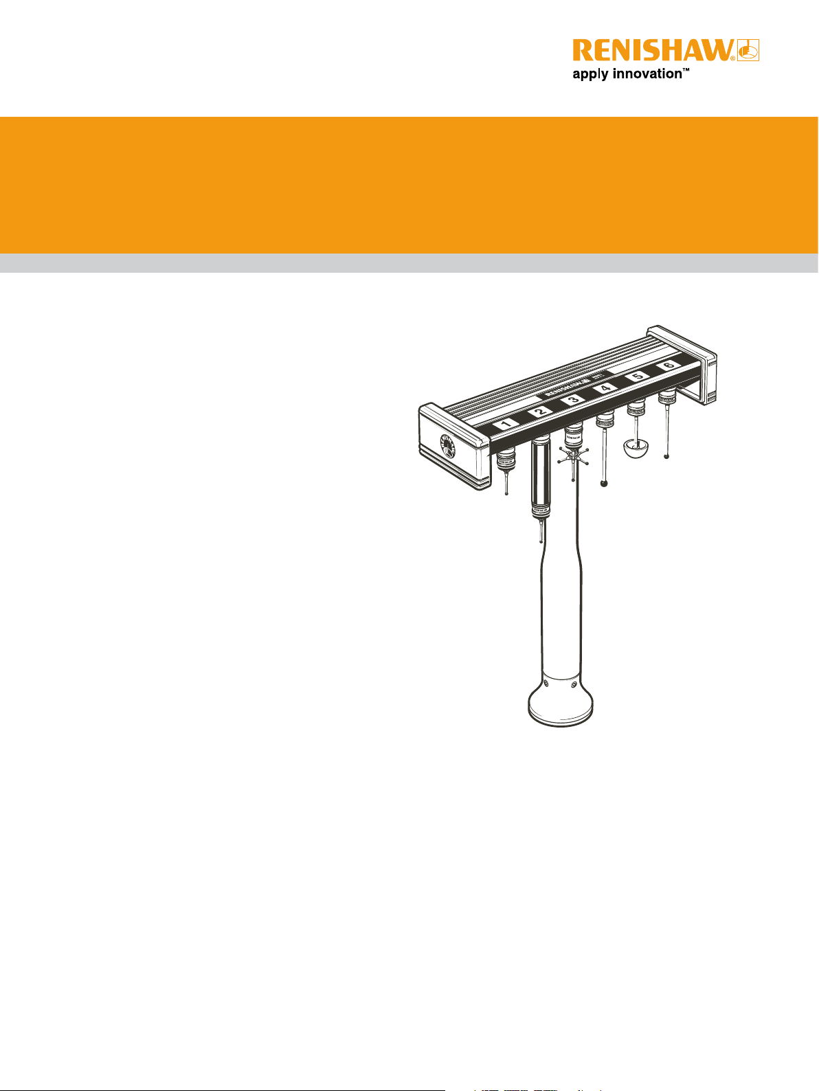
MSR1 manual storage rack for TP20
and TP200 stylus modules
• Provides safe storage for probe and stylus modules in
manual stylus changing applications.
• Stores up to 6 modules.
• Used with TP20 and TP200 probe modules.
Product description
The MSR1 manual storage rack provides convenient storage
for up to 6 probe or stylus assemblies, from the Renishaw
TP20 or TP200 probe range.
Using the rack
Install the rack in accordance with the instructions provided
overleaf headed ‘Installation instructions’. Refer to the
TP20 (part number, H-1000-5008) or TP200 (part number,
H-1000-5014) user’s guide for instructions about assembling
a stylus arrangement on the module and fitting the module to
the probe. Ensure that the stylus tip, threads and the magnetic
coupling of the modules are clean.
After qualification of the stylus tips, the module may be
removed from the probe body for storage in the rack. The
module should be handled for only the minimum length of time
and touching the stylus tip should be avoided. The modules
are magnetically held in the rack and may be orientated as
desired.
The location points are positioned approximately below the
numbered labels but accurate positioning is not necessary, as
the magnetic force will pull them to the correct position.
Dimensions
Overall height 285 mm
Depth (inc. wall bracket) 86 mm
Width 236 mm
Part number summary
MSR1 rack - wall mounting only A-1371-0330
MSR1 rack - CMM table mounting A-1371-0347
(wall bracket included)
Probe/stylus modules
TP20 TP20 standard force A-1371-0270
TP20 medium force A-1371-0271
TP20 extended force A-1371-0272
TP20 low force A-1317-0392
TP20 6-way A-1371-0419
TP20 extended module 1 (50 mm) A-1371-0430
TP20 extended module 2 (74 mm) A-1371-0431
TP200 TP200 standard force A-1207-0010
TP200 low force A-1207-0011
Page 2

Renishaw plc
New Mills, Wotton-under-Edge,
Gloucestershire, GL12 8JR
United Kingdom
T +44 (0)1453 524524
F +44 (0)1453 524901
E uk@renishaw.com
www.renishaw.com
Installation instructions
Mounting on the CMM table
CAUTION: The MSR1 rack is not crash protected. It is
!
recommended that the rack is mounted outside or close
to the edge of the working volume of the CMM.
1. Place the base over a threaded insert at the desired
location on the CMM table and screw down using the M8
or M10 bolt supplied.
2. Screw the leg a few turns into the M10 nut located in the
underside of the rack extrusion. Slide along to the centre
or other location, as required, and tighten by hand.
3. Push the lower end of the leg firmly into the base and
rotate the rack to the required orientation. Tighten the
grubscrews using the hexagon key supplied.
Wall mounting
1. Fix the wall mounting bracket (supplied) in the desired
location using the holes or other secure means.
2. Locate the rack on the bracket and secure by engaging the
M10 bolt (supplied) a few turns into the M10 nut located
in the underside of the rack extrusion. Slide the rack along
until it is centralised or otherwise located as required and
tighten the bolt.
Maintenance
Refer to the TP20 (part number, H-1000-5008) or TP200 (part
number, H-1000-5014) user’s guide.
Rack
Mounting bolt
M10 nut locates in
extrusion
Leg
Snap ring
Base
Grub screws
M4 x 4
If the rack is used in a metal machining environment it may be
necessary to periodically inspect the module locations for the
presence of magnetic dust or metal particles and clean using
the CK200 cleaning material supplied with the probe.
For worldwide contact details, please visit our
main web site at www.renishaw.com/contact
RENISHAW HAS MADE CONSIDERABLE EFFORTS TO ENSURE THE CONTENT OF THIS DOCUMENT IS CORRECT
AT THE DATE OF PUBLICATION BUT MAKES NO WARRANTIES OR REPRESENTATIONS REGARDING THE CONTENT.
RENISHAW EXCLUDES LIABILITY, HOWSOEVER ARISING, FOR ANY INACCURACIES IN THIS DOCUMENT.
© 2000 - 2008 Renishaw plc. All rights reserved. Part no. H-1000-5038-02-A Issued 08.08
Wall mounting
bracket
*H-1000-5038-02*
 Loading...