

Page 1
User’s guide
H-1000-5190-05-A
MH8
Page 2

© 2003 - 2004 Renishaw plc. All rights reserved.
Renishaw® is a registered trademark of Renishaw plc.
This document may not be copied or reproduced in whole or
in part, or transferred to any other media or language, by any
means, without the prior written permission of Renishaw.
The publication of material within this document does not imply
freedom from the patent rights of Renishaw plc.
Disclaimer
Considerable effort has been made to ensure that the contents
of this document are free from inaccuracies and omissions.
However, Renishaw makes no warranties with respect to the
contents of this document and specifi cally disclaims any implied
warranties. Renishaw reserves the right to make changes to this
document and to the product described herein without obligation
to notify any person of such changes.
Trademarks
All brand names and product names used in this document
are trade names, service marks, trademarks, or registered
trademarks of their respective owners.
Renishaw part no: H-1000-5190-05-A
Issued: 08 2004
Page 3

Renishaw plc
MH8 user’s guide
English - see part 1
Manuel de l’utilisateur MH8
Français - voir patie 2
Benutzerhandbuch MH8
Deutsch - siehe Abschnitt
Guida per l’utente MH8
Italiano - vedi Sez.
1
Page 4

2
This page intentionally left blank
Page 5

MH8 user’s guide
Part 1 - English
MH8 user’s guide
3
Page 6

4
© 2001 - 2004 Renishaw. All rights reserved.
Renishaw® is a registered trademark of Renishaw plc.
This document may not be copied or reproduced in whole or in part, or
transferred to any other media or language, by any means without the
written prior permission of Renishaw.
The publication of material within this document does not imply freedom
from the patent rights of Renishaw plc.
Disclaimer
Considerable effort has been made to ensure that the contents of this
document are free from inaccuracies and omissions. However, Renishaw
makes no warranties with respect to the contents of this document and
specifi cally disclaims any implied warranties. Renishaw reserves the right
to make changes to this document and to the product described herein
without obligation to notify any person of such changes.
Care of equipment
Your Renishaw probe and accessories are precision instruments. Please
use and maintain the products in accordance with these instructions and
retain the transit box for storing the components when not in use.
Changes to specifi cation
Renishaw plc may modify or change its products or specifi cations without
notice and without obligation.
Warranty
Renishaw plc warrants its products provided they are installed as defi ned in
the associated Renishaw documentation.
Consent must be obtained from Renishaw plc if non-Renishaw equipment
(such as interfaces or cabling) is to be used or substituted. Failure to do
this may invalidate the Renishaw warranty.
Patents
Aspects of the MH8 indexable probe and aspects of similar systems are
the subjects of the following patents and patent applications.
EP 0392660 JP 3,018,015 US 5,088,337
MH8 user’s guide
Page 7

Contents
Contents
1 Introduction ...................................................................................6
2 Product description .......................................................................7
2.1 Part number summary ........................................................10
3 Installation procedure ..................................................................11
3.1 Mounting the shank on the probe head ..............................11
3.2 Mounting the head on the CMM .........................................11
3.3 Electrical connection ..........................................................12
3.4 Mounting the probe to the probe head ...............................12
3.5 Extension bars ...................................................................13
4 Head operation ............................................................................14
4.1 To change the orientation of the probe ...............................14
5 Dimensions .................................................................................16
6 Technical specifi cation ................................................................17
6.1 Measuring performance .....................................................17
6.2 Technical data ....................................................................17
7 Maintenance ................................................................................18
5
8 Fault fi nding .................................................................................19
Page 8

6
Introduction
1 Introduction
The MH8 is a manually operated, indexing probe head that
articulates to provide orientation of the stylus. The head can carry
probes fi tted with a Renishaw M8 connector. The TP20 and TP6
touch trigger probes are recommended. The MH8 is available with a
range of shanks to suit the mounting arrangement specifi ed by the
manufacturer of the CMM.
Page 9

Product description
2 Product description
The MH8 has 2 axes. The probe connector is carried on the A axis
which can rotate the probe through 90° in the Z plane. The B axis can
rotate the probe through ±180° in the X-Y plane.
A lever actuated mechanism locks both axes in the desired position for
gauging the workpiece. The axes are unlocked to allow free rotation to
another position. The locked positions are set at angular increments of
15° in each axis, providing a total of 168 positions.
When the head orientation is locked, the probe is kinematically
constrained in a highly repeatable spatial position. This means that
after initial qualifi cation of the stylus tip, in the positions required for
gauging the workpiece, the probe may be reorientated to any of the
qualifi ed positions without the need for requalifi cation.
A red LED is provided on the front of the head to indicate the
probe’s status. The LED may be driven by the CMM controller or by
a Renishaw probe interface. It is convention for the LED to be ON to
indicate a seated (armed) probe and to be OFF to indicate a triggered
probe.
Electrical connection is via a 5 pin DIN connector.
7
Page 10
8
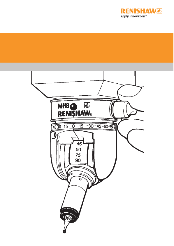
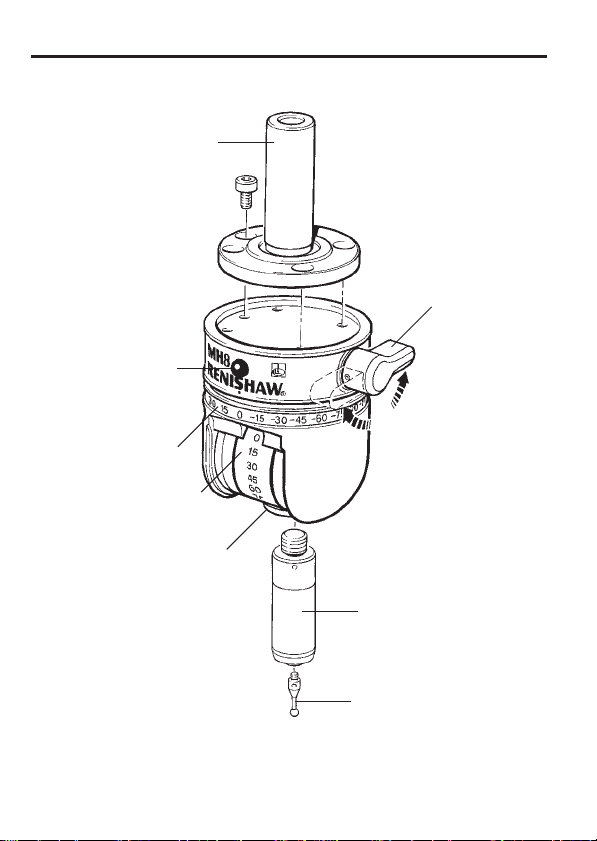
Product description
Probe status LED
B axis scale
A axis scale
M8 probe connector
Shank
Lock lever
Probe
Stylus
Figure 1 - The MH8 indexible head (front)
Page 11
Product description
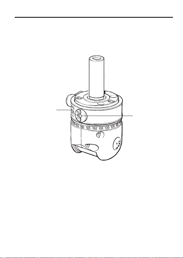
9
Serial number
label
Figure 2 - The MH8 indexible head (back)
5 pin DIN
connector
Page 12

10
Product description
2.1 Part number summary
Part number Descritpion
A-1332-0013 MH8 probe head + MH8 user’s guide (H-1000-5190)
A-1332-0002 MH8 probe head + TK4 probe tools (no shank)
A-1332-0003 MH8 + TK4 + MS1 shank
A-1332-0004 MH8 + TK4 + MS2 shank
A-1332-0005 MH8 + TK4 + MS4 shank
A-1000-0006 MH8 + TK4 + MS5 shank
A-1332-0007 MH8 + TK4 + MS7 shank
A-1332-0008 MH8 + TK4 + MS9 shank
A-1332-0009 MH8 + TK4 + MS10 shank
A-1332-0010 MH8 + TK4 + MS13 shank
A-1332-0011 MH8 + TK4 + MS15 shank
A-1332-0014 MH8 + TK4 + MS17 shank
A-1332-0012 MH8 + TK4 + D shank
A-1042-1486 S1 ‘C’ spanner
A-1047-3932 S9 double ended ‘C’ spanner
M-5000-3540 S7 stylus tightening tool
P-TL03-0150 Hexagon key, 1.5 mm AF (TP2/TP6 adjustment)
Page 13

Installation procedure
11
3 Installation procedure
3.1 Mounting the shank on the probe head
• Hold the shank in the recess on the top face of the MH8.
• Rotate the shank until 3 screw holes are aligned.
• Fix the shank in place using only the M3 x 5 mm screws
(supplied).
• Progressively tighten using the 2.5 mm A/F hexagon key
(supplied).
3.2 Mounting the head on the CMM
The head will normally be attached to the quill of the CMM using a
standard shank, specifi ed by the CMM manufacturer.
Standard shanks are listed in the section 2.1, ‘Part number summary’.
Special or customised mounting arrangements are possible. Please
contact your supplier or Renishaw, for details of our custom products
service.
The mounting must be absolutely rigid, as any movement during
normal operation of the head will add errors to the measurement
system.
If the head is replaced or repositioned in the quill, it will be necessary
to requalify all of the head positions in current use.
Page 14
12
Installation procedure
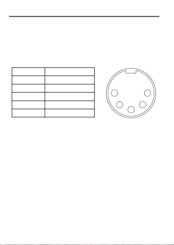
3.3 Electrical connection
Connection is by means of a 5 pin DIN connector on the side of the
heads (see fi gure 2).
The pin numbering functions are given in the table below:
Pin number Designation
1 LED cathode
2 Ground
3 LED anode
4 Probe circuit
5 Probe circuit
5
4
1
2
3
3.4 Mounting the probe to the probe head
If fi tting a TP20 probe, mount the probe body to the probe head before
fi tting the probe module and stylus.
• Screw the threaded end of the probe into the M8 connector on the
probe head until it is fi nger tight.
• Fit the S1 ‘C’ spanner (supplied) to the location holes in the probe
body and tighten by hand.
• The recommended tightening torque is 0.3 Nm – 0.5 Nm.
Refer also to the user’s guide for the probe type being used.
Page 15
Installation procedure
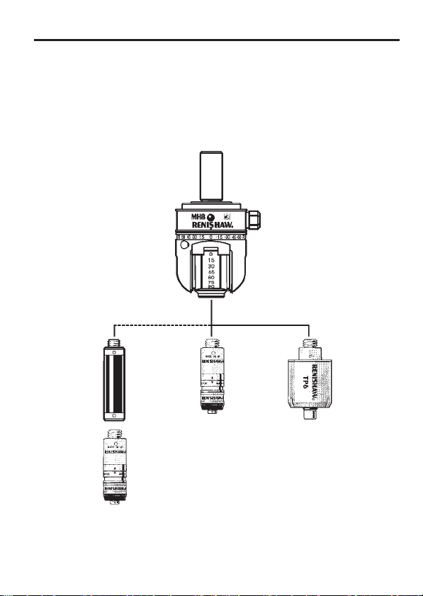
3.5 Extension bars
Probe reach may be extended by 50 mm using a PEL1 extension
bar. Use of the PEL2, PEL3 or PE series extension bars is not
recommended.
13
PEL1
TP20
TP20
TP6
Figure 3 - Using extension bars
Page 16

14
Head operation
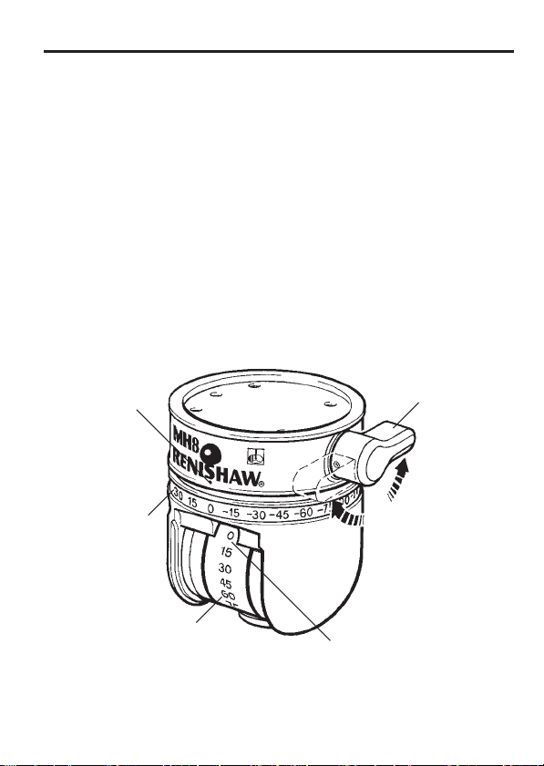
4 Head operation
NOTE: Ensure that the lock lever is turned fully clockwise to the
locked position, before taking gauge points.
4.1 To change the orientation of the probe
(refer to fi gure 4)
• Unlock the head by turning the lock lever to the fully anti-clockwise
position.
• Grip the body of the probe (avoid touching the stylus) and rotate
the ‘B’ axis until the desired angle indication on the scale (in
increments of 15°) is adjacent to the ‘B’ axis reference mark.
Rotate the ‘A’ axis until the desired angle indication on the scale
(in increments of 15°) is at the ‘A’ axis reference position.
• Lock the head by turning the lock lever to the fully clockwise
position.
• Qualify the stylus tip(s) according to the CMM supplier’s
instructions.
• Change the orientation of the probe to the next desired position
and qualify the stylus tip(s).
• Repeat the qualifi cation process for all desired orientations and
stylus tips.
• Commence gauging, ensuring that the correct qualifi cation data is
recalled for each head position.
Page 17
Head operation
Periodic requalifi cation should be performed according to the following
considerations:-
• CMM supplier’s recommendations, particularly in respect of
temperature changes.
• At the start of the working day or shift.
• After an accidental collision.
• After changing any measuring system component (except a prequalifi ed TP20 module).
• If the initial state is unknown or uncertain.
15
B axis
reference mark
B axis scale
A axis scale
Lock lever
Unlock
Lock
A axis
reference mark
Figure 4 - Locking lever operation
Page 18
16
Dimensions
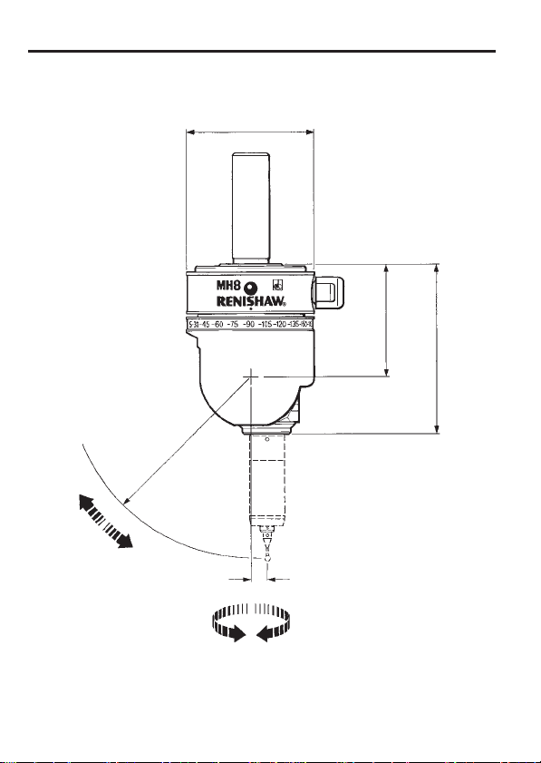
5 Dimensions
R70 *
A axis
0° - 90°
Ø48 mm
43 mm
65 mm
5.7 mm
* Using TP20 with LF/
B axis
±180°
Figure 5 - MH8 dimensions
SF/MF/EF module
and 10 mm stylus
Page 19

Technical specifi cation
6 Technical specifi cation
Refer to fi gure 5 for overall dimensions.
6.1 Measuring performance
Positional repeatability (2σ) 1.5 µm
(At stylus tip with TP20 probe, standard force
module and 10 mm stylus length)
Positional repeatability (2σ) 2.5 µm
with 50 mm extension bar (PEL1)
(At stylus tip with TP20 probe, standard force
module and 10 mm stylus length)
6.2 Technical data
17
Range of articulation
Maximum load
Operating temperature
range
Storage temperature range
Probe connector
Electrical connector
Sealing
Weight
A axis: 0° to 90° in 15° increments
B axis: ±180° in 15° increments
TP6 - no extension allowed
TP20 or TP2 probe + 50 mm
extension (PEL1)
+10 °C to +40 °C
-10 °C to +70 °C
Renishaw M8 x 1.25 x 5 mm
5 pin DIN (180°)
IP30
205 g (without shank)
Page 20

18
Maintenance
7 Maintenance
This product is intended for use in a protected metrology environment
and therefore accumlations of dust or swarf should not occur.
In common with all precision measuring equipment, regular
inspection and cleaning are recommended to ensure continued high
performance.
Maintenance is limited to wiping the outer surfaces, axes scale labels
and mounting face of the probe connector with a clean, dry cloth or
proprietary cleaning material.
Page 21

Fault fi nding
8 Fault fi nding
Refer also to the appropriate user’s guide for the probe.
Loss of measuring accuracy
Possible causes Remedy
Mounting not secure. Check that the MH8 is correctly
mounted to the shank and that
the screws are secure. Check
the clamping mechanism in the
CMM quill.
MH8 not fully locked. Ensure that the lock lever is
turned fully clockwise.
Excessive force imparted to
probe after locking.
MH8 overloaded. Use only with the specifi ed
Faulty probe. Check by substitution.
MH8 worn or damaged. Check by substitution or return
Axes ‘rattle’ when rotated
Possible causes Remedy
MH8 not fully unlocked. Turn lock lever fully anti-
Unlock and re-lock the MH8.
probe and extension
combinations.
to Renishaw or your supplier.
clockwise before attepting to reorientate probe.
19
Page 22

20
Manuel de l’utilisateur MH8
Page vide
Page 23

Manuel de l’utilisateur MH8
Partie 2 - Français
Manuel de l’utilisateur MH8
21
Page 24

22
© 2001 Renishaw. Tous droits réservés.
Renishaw® est une marque déposée de Renishaw plc.
Ce document ne peut être copié ni reproduit, dans sa totalité ni en partie, ni
transféré sous une autre forme ou langue, par des moyens quelconques, sans
l’autorisation écrite de Renishaw.
La publication d’informations contenues dans ce document n’implique en
aucun cas une exemption des droits de brevets de Renishaw plc.
Dénégation
Un effort considérable a été fourni afi n d’assurer que le contenu de ce
document ne contient aucune omission ni inexactitude. Cependant, Renishaw
ne garantit aucunement le contenu de ce document et dénie en particulier
toutes garanties supposées. Renishaw se réserve le droit d’apporter des
modifi cations à ce document et au produit qu’il décrit sans obligation d’en
informer quiconque.
Precautions d’emploi
Votre palpeur Renishaw et ses accessoires sont des instruments de précision
que nous vous recommandons d’utiliser et entretenir conformément à ce
mode d’emploi. Nous vous recommandons également de conserver son
emballage de transport afi n de pouvoir y ranger les composants après emploi.
Changement de caractéristiques
Renishaw plc se réserve le droit de modifi er ou changer ses produits ou leurs
caractéristiques sans préavis et sans obligations vis-à-vis des clients.
Garantie
La garantie prévue par Renishaw plc s’applique aux produits Renishaw
installés conformément aux données de la documentation y afférente.
Le matériel ne provenant pas de Renishaw (interfaces ou câblage, par
exemple) ne peut être utilisé ou substitué sans l’accord préalable de
Renishaw plc. Tout manquement à cette règle pourrait entraîner l’annulation
de la garantie Renishaw.
Brevets
Les aspects du palpeur réglable MH8 et d’autres systèmes ont fait l’objet des
brevets et dépôts de brevet suivants :
EP 0392660 JP 3,018,015 US 5,088,337
Manuel de l’utilisateur MH8
Page 25

Sommaire
23
Sommaire
1 Introduction .................................................................................24
2 Description du produit .................................................................25
2.1 Références des MH8 avec attachement ............................28
3 Procédure d’installation ...............................................................29
3.1 Montage de l’attachement sur la tête MH8 ........................29
3.2 Montage de la tête sur la MMT ..........................................29
3.3 Raccordement électrique ...................................................30
3.4 Montage du capteur sur la tête MH8 ..................................30
3.5 Allonges .............................................................................31
4 Fonctionnement de la tête ...........................................................32
4.1 Pour changer l’orientation du palpeur ................................32
5 Dimensions .................................................................................34
6 Caractéristiques techniques ........................................................35
6.1 Contrôle du fonctionnement ...............................................35
6.2 Fiche technique ..................................................................35
7 Entretien ......................................................................................36
8 Dépannage ..................................................................................37
Page 26

24
Introduction
1 Introduction
La MH8 est une tête articulée manuelle, permettant d’orienter
le capteur. La tête utilise les capteurs équipés d’un fi letage M8
Renishaw. Nous préconisons l’emploi des capteurs à déclenchement
de type TP20 et TP6 ou TP2. La tête MH8 se monte sur le coulisseau
de la MMT grâce à un attachement vissé sur sa partie supérieure. Les
dimensions de cet attachement dépendent de la marque et du type de
machine à mesurer MMT sur laquelle la MH8 doit être installée.
Page 27

Description du produit
25
2 Description du produit
Là tête MH8 est munie de deux axes pivotants. Le connecteur est
situé sur la partie fi xe supérieure. L’axe A permet de faire pivoter le
palpeur de 0° à 90° par rapport au plan Z. L’axe B permet d’orienter le
palpeur sur “180° sur le plan X/Y.
Un mécanisme à levier verrouille les deux axes dans la position
voulue pour mesurer la pièce. Le déverrouillage des axes permet
de faire pivoter le palpeur et l’orienter dans une autre position. Les
positions de verrouillage sont fi xées par paliers de 15° sur chaque axe.
L’utilisateur bénéfi cie par conséquent, de 168 positions différentes.
Une fois la tête verrouillée, le palpeur est bloqué dans une position
répétable. Autrement dit, après qualifi cation sur la sphère d’étalonnage
du stylet suivant les différentes positions, le palpeur peut être orienter
en fonction des points à palper sur la pièce à contrôler sans avoir à requalifi er sa position.
La MH8 est munie d’une LED rouge indiquant l’état du palpeur. La
LED peut être commandée par le contrôleur de la MMT ou par le biais
d’une interface Renishaw. Selon la convention généralement adoptée,
une LED allumée indique un palpeur au repos (hors matière), une
LED éteinte indique un palpeur déclenché (contact avec matière).
La connexion électrique du palpeur se fait par l’intermédiaire d’un
connecteur spécifi que DIN 5 broches 180°.
Page 28

26
Description du produit
Attachement
LED d’état du
palpeur
Echelle graduée
de l’axe B
Echelle graduée de
Fixation du capteur à
Levier de
verrouillage
l’axe A
fi letage M8
Capteur
Stylet
Figure 1 - Tête réglable MH8 (avant)
Page 29

Description du produit
27
Numéro de série
Figure 2 - Tête réglable MH8 (arrière)
Connecteur
DIN à 5
broches
Page 30

28
Description du produit
2.1 Références des MH8 avec attachement
Référence Désignation
A-1332-0013 Tête MH8 + guide de l’utilisateur du palpeur MH8
(H-1000-5190)
A-1332-0002 Tête MH8 et outils de palpeur TK4 (sans
attachement)
A-1332-0003 MH8 + TK4 + attachement MS1
A-1332-0004 MH8 + TK4 + attachement MS2
A-1332-0005 MH8 + TK4 + attachement MS4
A-1000-0006 MH8 + TK4 + attachement MS5
A-1332-0007 MH8 + TK4 + attachement MS7
A-1332-0008 MH8 + TK4 + attachement MS9
A-1332-0009 MH8 + TK4 + attachement MS10
A-1332-0010 MH8 + TK4 + attachement MS13
A-1332-0011 MMH8 + TK4 + attachement MS15
A-1332-0014 MH8 + TK4 + attachement MS17
A-1332-0012 MH8 + TK4 + attachement D
A-1042-1486 Clé ‘C’ S1
A-1047-3932 Clé ‘C’ à deux bouts S9
M-5000-3540 Outil de serrage du stylet S7
P-TL03-0150 Clé hexagonale AF 1,6 mm (réglage TP2/TP6)
Page 31

Procédure d’installation
29
3 Procédure d’installation
3.1 Montage de l’attachement sur la tête
MH8
• Maintenir l’attachement dans la gorge située sur la face
supérieure de la MH8.
• Faire pivoter l’attachement jusqu’à ce que les trois trous de vis
soient alignés.
• Bloquer l’attachement en place en utilisant uniquement des vis
M3 x 5 mm (fournies).
• Serrer progressivement à l’aide de la clé hexagonale A/F de
2,5 mm (fournie).
3.2 Montage de la tête sur la MMT
La tête se monte normalement sur le coulisseau de la MMT l’aide d’un
attachement standard spécifi é par le fabricant de la machine.
Un montage spécial ou une utilisation spécifi que de la MH8 peuvent
être envisagés. Veuillez contacter votre fournisseur ou Renishaw pour
de plus amples détails sur notre service de fourniture de produits
spéciaux.
Le montage doit être absolument rigide. En effet, tout mouvement
survenant pendant le fonctionnement normal de la tête entraînerait
des erreurs au niveau du système de mesure.
Tout démontage de la tête ou modifi cation de sa position par
rapport au coulisseau de la MMT obligent à procéder à une nouvelle
qualifi cation des positions du palpeur.
Page 32

30
Procédure d’installation
3.3 Raccordement électrique
La connexion de la MH8 s’effectue par le biais d’une prise DIN à 5
broches située sur le côté de la tête (voir Figure 2).
Les fonctions de chaque broche sont indiquées dans le tableau cidessous.
Réf. fi che Dénomination
1 Cathode LED
2 Masse
3 Anode LED
4 Circuit palpeur
5 Circuit palpeur
5
4
1
2
3
3.4 Montage du capteur sur la tête MH8
En cas de montage du capteur TP20, visser le corps du TP20 sur la
tête avant de monter le module et son stylet.
• Visser et serrer à la main l’extrémité fi letée du capteur dans le
connecteur M8 de la MH8.
• Utiliser la clé S1 ‘C’ (fournie) dans les trous de centrage du corps
du capteur et serrer à la main.
• Le couple de serrage recommandé se situe entre 0,3 et 0,5 Nm.
Consulter également le guide utilisateur se rapportant au type de
capteur utilisé.
Page 33

Procédure d’installation
3.5 Allonges
La portée du palpeur peut être prolongée de 50 mm par ajout d’une
rallonge PEL1.
L’utilisation d’allonges des séries PEL2, PEL3 ou PE n’est pas
recommandée.
31
PEL1
TP20
TP20
TP6
Figure 3 – Montage d’une allonge
Page 34

32
Fonctionnement de la tête
4 Fonctionnement de la tête
REMARQUE: Vérifi er que le levier de verrouillage est bien tourné à
fond dans le sens horaire en position verrouillée, avant toute mesure.
4.1 Pour changer l’orientation du palpeur
(voir fi gure 4)
• Déverrouiller la tête en faisant tourner le levier de verrouillage à
fond, dans le sens anti-horaire.
• Bien tenir le corps du palpeur (en évitant de toucher au stylet) et
faire tourner l’axe ‘B’ jusqu’à ce que le repère d’angle voulu de
l’échelle graduée (par paliers de 15°) tombe en face du repère de
référence de l’axe ‘B’. Faire tourner l’axe ‘A’ jusqu’à ce le repère
d’angle voulu de l’échelle graduée (par paliers de 15°) tombe en
face du repère de référence de l’axe ‘A’.
• Bloquer la tête en faisant tourner le levier de verrouillage à fond
dans le sens horaire.
• Etalonner le capteur et son stylet conformément aux instructions
du fabricant de la MMT.
• Changer l’orientation du palpeur suivant la prochaine position
souhaitée et procéder à un nouvel étalonnage.
• Répéter le processus d’étalonnage pour chaque nouvelle
orientation du capteur et de son stylet.
• Effectuer la gamme de mesures en vérifi ant que les valeurs
d’étalonnage sont bien réinitialisées pour chaque position de la
tête.
Page 35

Fonctionnement de la tête
La procédure d’étalonnage ou qualifi cation doit être suivie
régulièrement, en tenant compte des aspects suivants:
• Recommandations du fabricant de la MMT, surtout en ce qui
concerne les fl uctuations de température.
• En début de journée ou lors de la mise en route de la MMT.
• Après une collision accidentelle.
• Après remplacement de l’un des éléments du système de palpage
(à l’exception du module TP20 pré-positionné).
• En cas d’état initial inconnu ou de doute à ce sujet.
33
Echelle
graduée de
l’axe B
Repère de
référence de
l’axe B
Repère de
référence de
l’axe A
Echelle graduée
de l’axe A
Levier de
verrouillage
Déverrouiller
Verrouiller
Figure 4 - Fonctionnement du levier de verrouillage
Page 36

34
Dimensions
5 Dimensions
R70
Axe A
0° - 90°
Ø48 mm
43 mm
5.7 mm
Axe B
±180°
Figure 5 – Dimensions du palpeur MH8
Page 37

Technical specifi cation
6 Caractéristiques techniques
Consulter la fi gure 5 pour ce qui concerne les dimensions hors tout.
6.1 Performances du système de palpage
Répétabilité de positionnement (2σ) 1.5 µm
(Avec palpeur TP20, module de force
standard et stylet de 10 mm de long)
Répétabilité de positionnement (2σ) 2.5 µm
avec rallonge de 50 mm (PEL )
(Avec palpeur TP20, module de force
standard et stylet de 10 mm de long)
6.2 Fiche technique
Indexation paliers do 15° Axe A De 0 à 90° par paliers de 15°
Axe B ±180° par paliers de 15°
Charge maximale Palpeur TP6 - rallonge proscrite
TP20 ou TP2 + Allonge PEL1 50 mm
Plage de température
d’utilisation
Plage de température de
stockage
Connecteur de palpeur Renishaw M8 x 1,25 x 5 mm
Connecteur électrique DIN 5 fi ches (180°)
Protection IP30
Masse 205 g (sans attachement)
+10 à +40 °C
-10 à +70 °C
35
Page 38

36
Entretien
7 Entretien
Ce produit est conçu pour être utilisé dans un environnement de
métrologie protégé et ne doit par conséquent pas être soumis à des
risques d’accumulation de poussières ou de copeaux.
Comme c’est le cas pour tous les instruments de mesure de précision,
nous vous recommandons de contrôler et nettoyer régulièrement votre
tête MH8 pour garantir des performances optimales.
L’entretien se limite à l’essuyage de ses surfaces externes, étiquettes
d’échelle graduée d’axe et côté taraudage M8 à l’aide d’un chiffon
propre et sec ou d’un produit de nettoyage reconnu.
Page 39

Dépannage
8 Dépannage
Consulter également le guide de l’utilisateur prévu pour le capteur.
Perte de précision
Cause possible Solution
Fixation mal bloquée. Vérifi er que la MH8 est bien
MH8 mal verrouillé. Vérifi er que le levier de
Déplacement du palpeur après
verrouillage.
Surcharge du MH8. Utiliser seulement avec la
Palpeur défectueux. Vérifi er par remplacement.
MH8 usé ou endommagé. Vérifi er par remplacement ou
Les axes ‘vibrent’ en rotation.
Cause possible Solution
Le MH8 n’est pas complètement
déverrouillé.
montée sur l’attachement et
que les vis sont bien serrées.
Vérifi er le mécanisme de fi xation
de fi xation de la MH8 sur le
coulisseau de la MMT.
verrouillage est bien tourné à
fond dans le sens horaire.
Déverrouiller et verrouiller de
nouveau la MH8.
combinaison palpeur / rallonge
spécifi ée.
renvoyer à Renishaw ou à votre
fournisseur..
Faire pivoter le levier de
verrouillage à fond dans le sens
anti-horaire avant d’essayer de
réorienter la tête.
37
Page 40

38
MH8 Benutzerhandbuch39MH8 Benutzerhandbuch
Leere Seite
Page 41

Abschnitt 3 - Deutsch
MH8 Benutzerhandbuch
Page 42

40
© 2001 Renishaw. Alle Rechte vorbehalten.
Renishaw® ist ein eingetragenes Warenzeichen von Renishaw plc.
Dieses Dokument darf ohne vorherige schriftliche Genehmigung von Renishaw
weder ganz noch teilweise kopiert oder vervielfältigt werden oder auf irgendeine
Weise auf andere Medien oder in eine andere Sprache übertragen werden.
Die Veröffentlichung von Material in diesem Dokument impliziert keine Freiheit
von den Patentrechten von Renishaw plc.
Haftungsausschlußklausel
Es wurden beträchtliche Anstrengungen unternommen, um sicherzustellen, daß
der Inhalt dieses Dokuments frei von Ungenauigkeiten und Auslassungen ist.
Renishaw übernimmt jedoch keine Garantien für den Inhalt dieses Dokuments
und lehnt insbesondere jede implizite Garantie ab. Renishaw behält sich das
Recht vor, Änderungen an diesem Dokument und dem darin beschriebenen
Produkt vorzunehmen, ohne die Verpfl ichtung einzugehen, irgendeine Person
über solche Änderungen zu informieren.
Gerätepfl ege
Ihr Messtaster und Zubehör von Renishaw sind Präzisionsinstrumente.
Benutzen und pfl egen Sie diese Produkte bitte in Übereinstimmung mit
diesen Anleitungen und bewahren Sie sie bei Nichtbenutzung in ihren
Verpackungskartons auf.
Änderung technischer Daten
Renishaw kann Produkte oder technische Daten ohne vorherige Mitteilung und
unverbindlich ändern oder modifi zieren.
Garantie
Renishaw plc garantiert seine Produkte, solange sie in Übereinstimmung mit
den Defi nitionen in der entsprechenden Dokumentation von Renishaw installiert
werden.
Sollen Geräte von Fremdherstellern (wie zum Beispiel Interfaces oder
Kabel) benutzt oder ersetzt werden, ist eine Genehmigung von Renishaw plc
einzuholen. Ein Nichteinhalten dieser Bestimmung kann zur Ungültigkeit der
Renishaw-Garantie führen.
Patente
Teile des indexierbaren Messtasters sowie Teile ähnlicher Systeme sind
Gegenstand der folgenden Patente und Patentanmeldungen:
EP 0392660 JP 3,018,015 US 5,088,337
MH8 Benutzerhandbuch
Page 43

Inhalt
41
Inhalt
1 Einleitung ....................................................................................42
2 Produktbeschreibung ..................................................................43
2.1 Übersicht der MH8-Bestellnummern ..................................46
3 Installation ...................................................................................47
3.1 Montage des Aufnahmeschaftes am MH8-Tastkopf ...........47
3.2 Montage des MH8-Tastkopfes am KMG ...........................47
3.3 Elektrischer Anschluss .......................................................48
3.4 Montage eines Messtasters am Tastkopf ...........................48
3.5 Verlängerungen / Messtasterkonfi gurationen .....................49
4 Benutzung des Tastkopfes ..........................................................50
4.1 Positionieren des Tastkopfes ..............................................50
5 Abmessungen .............................................................................52
6 Technische Spezifi kation .............................................................53
6.1 Messleistung ......................................................................53
6.2 Technische Daten ...............................................................53
7 Wartung .......................................................................................54
8 Fehlersuche ................................................................................55
Page 44

42
Einleitung
1 Einleitung
Der MH8 ist ein manuell indexierbarer Tastkopf mit Dreh- und
Schwenkfähigkeit, um das Positionieren der Tasterkonfi guration zu
ermöglichen. Der Tastkopf kann mit Messtastern verwendet werden,
die mit einer Renishaw M8 Aufnahme ausgestattet sind. Empfohlen
werden die taktil schaltenden Messtaster TP20 bzw. TP6. Der MH8 ist,
je nach der vom KMG-Hersteller spezifi zierten Schaftaufnahme der
KMG-Pinole, mit verschiedenen Aufnahmeschäften lieferbar.
Page 45

Produktbeschreibung
43
2 Produktbeschreibung
Der MH8 ist mit zwei indexierbaren Gelenkachsen A und B versehen.
Die Messtasteraufnahme befi ndet sich auf dem Gelenk der A-Achse,
über die der Messtaster von 0° bis auf 90° in der Z-Ebene geschwenkt
werden kann. Die B-Achse kann den Messtaster auf der Ebene X-Y
um ±180° bewegen.
Über einen hebelbetriebenen Mechanismus werden beide Achsen
zum Messen des Werkstückes in der gewünschten Position
verriegelt. Die Achsen werden entriegelt, um eine freie Dreh/Schwenkbewegung in eine andere Position zu ermöglichen. Die zum
Messen des Werkstückes erforderlichen Positionen können in beiden
Achsen in 15° Schritten eingestellt werden. Insgesamt stehen also 168
Positionen zur Verfügung.
Im verriegelten Zustand des MH8 befi ndet sich die
Messtasterkonfi guration in einer kinematisch reproduzierbaren
räumlichen Position. Dies bedeutet, dass die Messtasterkonfi guration
nur einmal in der für die Messaufgabe erforderlichen Position kalibriert
werden muss. Danach kann diese Position immer wieder exakt
eingenommen werden.
Ein rotes LED an der Frontseite des MH8 Tastkopfes zeigt den
Status des Messtasters an. Das LED kann von der KMG-Steuerung
oder von einem Renishaw Messtaster Interface betrieben werden.
Normalerweise leuchtet die LED im Ruhezustand und erlischt bei
ausgelenktem Messtaster, um damit ein Tastsignal anzuzeigen.
Der elektrische Anschluss erfolgt über eine 5-polige DIN
Steckverbindung.
Page 46

44
Positionsmarkierung
Produktbeschreibung
Aufnahmeschaft
LED für
Messtaster-Status
für B-Achse
Positionsmarkierung
für A-Achse
Messtasteraufnahme
mit M8-Gewinde
Klemmhebel
Messtaster
Tasteinsatz
Abbildung 1 – Manuell indexierbarer Tastkopf MH8
(Vorderansicht)
Page 47

Produktbeschreibung
45
Seriennummer
5-polige DinSteckverbindung
Abbildung 2 – Der indexierbare Tastkopf des MH8
(Rückansicht)
Page 48

46
Produktbeschreibung
2.1 Übersicht der MH8-Bestellnummern
Bestellnummer Beispiel
A-1332-0013 Tastkopf MH8 + Bedienungsanleitung MH8
(H-1000-5190)
A-1332-0002 Tastkopf MH8 und TK4 Messtaster-
Montagewerkzeug (ohne Aufnahmeschaft)
A-1332-0003 MH8 + TK4 + MS1 Aufnahmeschaft
A-1332-0004 MH8 + TK4 + MS2 Aufnahmeschaft
A-1332-0005 MH8 + TK4 + MS4 Aufnahmeschaft
A-1000-0006 MH8 + TK4 + MS5 Aufnahmeschaft
A-1332-0007 MH8 + TK4 + MS7 Aufnahmeschaft
A-1332-0008 MH8 + TK4 + MS9 Aufnahmeschaft
A-1332-0009 MH8 + TK4 + MS10 Aufnahmeschaft
A-1332-0010 MH8 + TK4 + MS13 Aufnahmeschaft
A-1332-0011 MH8 + TK4 + MS15 Aufnahmeschaft
A-1332-0014 MH8 + TK4 + MS17 Aufnahmeschaft
A-1332-0012 MH8 + TK4 + D Aufnahmeschaft
A-1042-1486 S1 C-Spannschlüssel
A-1047-3932 S9 ‘Doppelter C-Spannschlüssel
M-5000-3540 S7 Stiftschlüssel für M8/M3 Tastereinsätze
P-TL03-0150 S3 1,5 mm Sechskantschlüssel (TP2/TP6-
Einstellung)
Page 49

Installation
47
3 Installation
3.1 Montage des Aufnahmeschaftes am
MH8-Tastkopf
• Setzen Sie den Aufnahmeschaft in die Aussparung an der
Oberseite des MH8-Tastkopfes.
• Drehen Sie den Aufnahmeschaft, bis alle Schraubenlöcher
aufeinander ausgerichtet sind.
• Befestigen Sie den Aufnahmeschaft. Benutzen sie dazu nur die
(mitgelieferten) M3 x 5 mm Schrauben.
• Ziehen Sie die Schrauben nach und nach an. Verwenden Sie dazu
den (mitgelieferten) 2,5 mm A/F Sechskantstiftschlüssel.
3.2 Montage des MH8-Tastkopfes am KMG
Der MH8-Tastkopf wird in der Regel unter Verwendung eines vom
Hersteller spezifi zierten Standardschaftes an die KMG-Pinole
befestigt.
Standardschäfte sind im Abschnitt „Übersicht der MH8Bestellnummern” aufgeführt.
Spezielle oder kundenspezifi sche Montageanordnungen sind möglich.
Für Einzelheiten über unseren Sonderprodukt-Service setzen Sie sich
bitte mit Ihrem Händler oder Renishaw in Verbindung.
Die Montage muss vollkommen starr sein, da eine Bew egung während
des Normalbetriebs des Tastkopfes zu möglichen Fehlern im MessSystem führen kann.
Wird der Tastkopf ersetzt oder seine Position an der Pinole geändert,
ist es erforderlich, alle gegenwärtig benutzten Kopfpositionen erneut
zu kalibrieren.
Page 50

48
Installation
3.3 Elektrischer Anschluss
Der Anschluss erfolgt über eine 5-polige DIN 180° Anschlußbuchse
seitlich am Kopf (siehe Abbildung 2).
Die Funktionen der einzelnen Stiftnummern sind der nachstehenden
Tabelle zu entnehmen:
Stiftnummer Bezeichnung
1 LED-Kathode
2 Masse
3 LED-Anide
4 Messtaster-Schaltkreis
5 Messtaster-Schaltkreis
5
4
1
2
3
3.4 Montage eines Messtasters am Tastkopf
Wird ein Messtaster TP20 angebracht, muss das Messtastergehäuse
vor Befestigung des Messtastermoduls und des Tasteinsatzes
montiert werden.
• Drehen Sie das Gewindeende des Messtasters in die M8Aufnahme am MH8-Tastkopf und ziehen Sie es handfest an.
• Setzen Sie den (mitgelieferten) S1 C Spannschlüssel in die
Positionslöcher im Messtastergehäuse ein und ziehen Sie es
handfest an.
• Das empfohlene Drehmoment ist 0,3 Nm bis 0,5 Nm.
Siehe auch die Bedienungsanleitung für den benutzten Messtastertyp.
Page 51

Installation
49
3.5 Verlängerungen /
Messtasterkonfi gurationen
Die Reichweite des Messtasters kann um 50 mm erweitert werden,
indem eine PEL1 Verlängerung benutzt wird. Die Verwendung von
Verlängerungen der Serien PEL2, PEL3 oder PE wird nicht empfohlen.
PEL1
TP20
TP20
TP6
Abbildung 3 – Verlängerungen /
Messtasterkonfi gurationen
Page 52

50
Benutzung des Tastkopfes
4 Benutzung des Tastkopfes
HINWEIS: Vergewissern Sie sich, dass der Klemmhebel bis zum
Endanschlag im Uhrzeigersinn gedreht wurde, bevor Messpunkte
aufgenommen werden.
4.1 Positionieren des Tastkopfes (siehe
Abbildung 4)
• Lösen Sie den Tastkopf, indem Sie den Klemmhebel bis zum
Endanschlag gegen den Uhrzeigersinn drehen.
• Halten Sie das Gehäuse der Messtasterkonfi guration fest
(ohne den Tastereinsatz zu berühren) und drehen Sie die BAchse in 15° Stufen, bis die gewünschte Winkelstufe auf der
Positionsmarkierung der B-Achse erscheint. Schwenken Sie
anschließend die A-Achse, bis die gewünschte Winkelstufe im
Positionsfenster der A-Achse erscheint. Nicht beide Achsen
gleichzeitig verstellen.
• Verriegeln Sie den Tastkopf fest, indem Sie den Sperrhebel bis zur
Feststellposition im Uhrzeigersinn drehen.
• Kalibrieren Sie die Tastereinsatzkonfi guration(en) nach Anweisung
ihres KMG-Herstellers.
• Verändern Sie die Position der Messtasterkonfi guration zur
nächsten gewünschten Position und kalibrieren diese im
Anschluss.
• Wiederholen Sie dieses Verfahren bis alle gewünschten Positionen
und Messtasterkonfi gurationen kalibriert sind.
• Beginnen Sie den Messvorgang und achten Sie darauf, dass
für jede einzelne Kopfposition und Messtasterkonfi guration die
entsprechenden Verrechnungsdaten aktiviert werden.
Page 53

Benutzung des Tastkopfes
Periodisches Nachkalibrieren sollte unter folgenden Bedingungen
durchgeführt werden:
• Nach Empfehlungen des KMG-Herstellers, insbesondere in Bezug
auf T emperaturänderungen.
• Zu Beginn des Arbeitstages oder der Schicht.
• Nach einer Kollision.
• Nach Änderung der Messtasterkonfi guration (mit Ausnahme eines
bereits kalibrierten TP20 Moduls).
• Wenn die Messabweichung zu hoch ist.
51
Positionsskala
der B-Achse
Positionsfenster
der B-Achse
Positionsskala
der A-Achse
Positionsfenster
der A-Achse
Abbildung 4 – Benutzung des Klemmhebels
Klemmhebel
Lösen
Feststellen
Page 54

52
Abmessungen
5 Abmessungen
Ø48 mm
R70
A-Achse
0° - 90°
43 mm
5.7 mm
B-Achse
±180°
Abbildung 5 – Abmessungen des MH8
Page 55

Technische Spezifi kation
6 Technische Spezifi kation
Für Gesamtabmessungen siehe Abbildung 5, Seite 50.
6.1 Messleistung
Reproduzierbarkeit von Tastkopfpositionen (2σ) 1.5 µm
(An der Tastspitze mit Messtaster TP20-SF und
10 mm Tastereinsatzlänge)
Wiederholbarkeit von Positionen (2σ) 2.5 µm
mit 50 mm Verlängerung (PEL1)
(An der Tastspitze mit Messtaster TP20-SF und
10 mm Tastereinsatzlänge)
6.2 Technische Daten
53
Schwenkbereich
Höchstlast
Temperaturbereich /
Betrieb
Temperaturbereich /
Lagerung
Messtasteraufnahme
Elektrische Verbindung
Einsatz in Gebäuden
Gewicht
A-Achse: 0° bis 90° in 15° Schritten
B-Achse: ± 180° in 15° Schritten
TP6 Messtaster -Verlängerung (PEL)
nicht zulässig
TP20 oder TP2 Messtaster + 50 mm
Verlängerung (PEL1)
+10 °C bis +40 °C
-10 °C bis +70 °C
Renishaw M8 Aufnahme
Anschlussbuchse 5-polig DIN 180°
IP30
205 g (ohne Aufnahmeschaft)
Page 56

54
Wartung
7 Wartung
Dieses Produkt ist für einen Einsatz in geschützten Messräumen
bestimmt, so dass Ansammlungen von Staub oder Spänen nicht
auftreten dürfen.
Wie alle Präzisionsmessinstrumente werden regelmäßige
Untersuchungen und Reinigung empfohlen, um anhaltend hohe
Leistungen zu gewährleisten.
Die Wartung ist auf ein Abreiben der Außenfl ächen, der
Messtasteraufnahme, der Positionsskalierung und der Montagefl ächen
der Messtasteraufnahme mit einem sauberen, trockenen Tuch oder
einem Markenreiniger beschränkt.
Page 57

Fehlersuche
8 Fehlersuche
Siehe auch die entsprechenden Bedienungsanleitungen für den
Messtaster.
Verminderte Messgenauigkeit
Mögliche Ursachen Korrektive Maßnahme
Montage nicht gesichert. Prüfen Sie, dass der MH8 richtig
MH8 nicht komplett verriegelt. Vergewissern Sie sich, dass
Nach dem Verriegeln wird Druck
/ Kraft auf den auf den MH8
Tastkopf ausgeübt.
MH8 überlastet.(Z.B.
unzulässige Verlängerung)
Fehlerhafter Messtaster. Tauschen sie den defekten
MH8 abgenutzt oder schadhaft. Tauschen Sie den defekten
am Aufnahmeschaft angebracht
ist und die Schrauben fest
angezogen sind. Prüfen Sie den
Klemm-Mechanismus in der
KMG-Pinole.
der Klemmhebel des MH8
Tastkopfes bis zum Anschlag im
Uhrzeigersinn gedreht wurde.
Entriegeln Sie den MH8 Tastkopf
und verriegeln ihn wieder.
Verwenden Sie den
MH8 Tastkopf nur mit
den max. zulässigen
Messtasterkombinationen.
Messtaster aus.
MH8-Tastkopf aus oder senden
Sie ihn an Renishaw oder Ihren
Händler zurück.
55
Page 58

56
Fehlersuche
Achsen ‘rattern’ beim Positionieren
Mögliche Ursachen Korrektive Maßnahme
MH8 wurde nicht vollkommen
entriegelt
Drehen Sie den Klemmhebel
bis zum Endanschlag gegen
den Uhrzeigersinn, bevor Sie
versuchen, den Messtaster neu
auszurichten.
Page 59

MH8 Istruzioni per l’uso
Sez. 4 - Italiano
MH8 Istruzioni per l’uso
57
Page 60

58
© 2001 Renishaw plc. Tutti i diritti riservati.
Renishaw ® è un marchio registrato della Renishaw plc.
È vietato copiare, riprodurre o trasmettere alcuna parte del documento
in qualsiasi forma ed in qualsiasi lingua, per qualsivoglia scopo e con
qualsiasi mezzo, senza l’espresso consenso della Renishaw plc.
La pubblicazione del materiale qui contenuto non esonera l’utente dai diritti
di brevetto della Renishaw plc.
Limite di responsabilità
Il presente documento è stato preparato con la massima attenzione per
garantire che sia esente da errori ed omissioni. La casa non garantisce
comunque la precisione delle informazioni qui contenute ed in particolare
respinge la garanzia implicita. Renishaw plc si riserva il diritto di apportare
modifi che al documento ed alle apparecchiature trattate senza incorrere
alcun obbligo di notifi ca.
Cura della prodotto
La sonda e i relativi accessori Renishaw sono strumenti di precisione. Si
prega di usare e sottoporre a manutenzione gli apparecchi osservando
le istruzioni qui fornite, nonché di conservare la scatola di spedizione per
tenervi i vari componenti quando non sono usati.
Modifi che della specifi ca
Renishaw plc può modifi care o cambiare i propri prodotti, o le loro
specifi che, senza preavviso e senza impegno.
Garanzia
Renishaw plc garantisce i propri prodotti purché siano installati come
specifi cato nell’allegata documentazione Renishaw.
Se si devono usare o sostituire apparecchiature (quali interfacce e cavi)
non di produzione Renishaw, bisogna ottenere innanzi tutto l’assenso della
Renishaw, altrimenti la garanzia Renishaw può risultare invalida.
Brevetti
Certi aspetti della testa indexabile MH8 e di sistemi simili sono oggetto dei
seguenti brevetti e domande di brevetto.
EP 0392660 JP 3,018,015 US 5,088,337
MH8 Istruzioni per l’uso
Page 61

Indice
59
Indice
1 Introduzione ................................................................................60
2 Descrizione del prodotto .............................................................61
2.1 Sommario dei codici pezzo ................................................62
3 Procedura d’installazione ............................................................65
3.1 Montaggio del codolo sulla testa MH8 ...............................65
3.2 Montaggio della testa sulla CMM .......................................65
3.3 Connessione elettrica .........................................................66
3.4 Montaggio del codolo sulla testa ........................................66
3.5 Barre di prolunga ................................................................67
4 Funzionamento della testa ..........................................................68
4.1 Per cambiare l’orientamento della sonda di misura ...........68
5 Dimensioni ..................................................................................70
6 Specifi ca tecnica .........................................................................71
6.1 Prestazioni di misurazione .................................................71
6.2 Dati tecnici ..........................................................................71
7 Manutenzione ..............................................................................72
8 Ricerca dei guasti ........................................................................73
Page 62

60
Introduzione
1 Introduzione
La MH8 è una testa index manuale che si articola per fornire
l’orientamento dello stilo di misura. La testa può accettare tastatori
dotati di connettore M8 Renishaw. Si raccomanda l’uso di tastatori
TP20 e TP6. La testa MH8 è disponibile con una vasta gamma di
codoli per adattarsi al sistema di montaggio specifi cato dal costruttore
della CMM.
Page 63

Descrizione del prodotto
61
2 Descrizione del prodotto
La MH8 ha 2 assi di rotazione. Il connettore della sonda viene montato
sulla parte girevole dell’asse A, che consente di far ruotare la sonda di
90° nel piano Z. L’asse B consente di fare ruotare la sonda di ±180°
nel piano X-Y.
Un meccanismo azionato a leva blocca entrambi gli assi sulla
posizione voluta. Gli assi possono essere sbloccati per consentire
la libera rotazione su un’altra posizione. Le posizioni bloccate sono
impostate con incrementi angolari di 15° per ciascun asse, per un
totale di 168 posizioni.
Quando la testa viene bloccata dopo l’orientamento, la sonda è
completamente vincolata cinematicamente in una posizione spaziale
altamente ripetibile. Ciò signifi ca che dopo la qualifi cazione iniziale
della punta dello stilo nelle posizioni richieste, la sonda può essere
nuovamente orientata su una qualsiasi delle posizioni qualifi cate
senza bisogno di riqualifi cazione.
Un LED rosso montato sulla parte anteriore della testa indica lo stato
della sonda. Il LED può essere comandato dall’unità di controllo della
CMM, oppure da un’interfaccia Renishaw della sonda. È convenzione
normale che il LED sia acceso per indicare che la sonda è posizionata
(armata) per la misura, e spento per indicare che la sonda è stata
azionata e delessa.
Le connessioni elettriche sono effettuate tramite un connettore DIN a
5 poli.
Page 64

62
Descrizione del prodotto
LED di stato
della sonda
Scala dell’asse B
Scala dell’asse A
Connettore sonda
Codolo
M8
Sonda
Leva di
bloccaggio
Stilo
Figura 1 – La testa indexabile MH8 (vista anteriore)
Page 65

Descrizione del prodotto
63
Etichetta del
numero di serie
Connettore
DIN a 5 poli
Figura 2 – La testa indexabile MH8 (vista posteriore)
Page 66

64
Descrizione del prodotto
2.1 Sommario dei codici pezzo
N. di codice Descrizione
A-1332-0013 Testa MH8 + guida d’uso utente (H-1000-5190)
A-1332-0002 Testa MH8 e set di utensili TK4 ( senza codolo)
A-1332-0003 MH8 + TK4 + codolo MS1
A-1332-0004 MH8 + TK4 + codolo MS2
A-1332-0005 MH8 + TK4 + codolo MS4
A-1000-0006 MH8 + TK4 + codolo MS5
A-1332-0007 MH8 + TK4 + codolo MS7
A-1332-0008 MH8 + TK4 + codolo MS9
A-1332-0009 MH8 + TK4 + codolo MS10
A-1332-0010 MH8 + TK4 + codolo MS13
A-1332-0011 MH8 + TK4 + codolo MS15
A-1332-0014 MH8 + TK4 + codolo MS17
A-1332-0012 MH8 + TK4 + codolo D
A-1042-1486 Chiave S1
A-1047-3932 Chiave S9
M-5000-3540 Utensile S7 di serraggio stilo
P-TL03-0150 Chiave esagonale da 1,5 mm AF (regolazione di
TP2/TP6)
Page 67

Procedura d’installazione
65
3 Procedura d’installazione
3.1 Montaggio del codolo sulla testa MH8
• Posizionare il codolo nell’incavo della superfi cie superiore della
MH8.
• Fare ruotare il codolo fi no ad allineare i 3 fori delle viti.
• Fissare il codolo in posizione usando solo le 3 viti M3 x 5 mm
(fornite).
• Serrare progressivamente usando la chiave esagonale da 2,5 mm
A/F (fornita).
3.2 Montaggio della testa MH8 sulla CMM
La testa viene normalmente fi ssata alla colonna della CMM usando un
codolo specifi cato dal fabbricante della CMM.
I codoli standard sono elencati nel capitolo “Sommario dei codici
pezzo”.
Si possono usare sistemi di montaggio speciali o personalizzati.
Contattare il proprio fornitore, o la Renishaw, per i particolari del
nostro servizio di personalizzazione dei prodotti.
Il montaggio deve essere assolutamente rigido, poiché qualsiasi
movimento durante il normale funzionamento della testa
aggiungerebbe errori al sistema di misurazione.
Se la testa, o la sua posizione sulla colonna, viene cambiata bisogna
riqualifi care tutte le posizioni della testa usate correntemente.
Page 68

66
Procedura d’installazione
3.3 Connessione elettrica
La connessione avviene tramite una presa DIN a 5 poli montata sul
lato della testa (vedere fi gura 2).
La tabella qui sotto descrive le funzioni di ciascun terminale.
Piedino Funzione
1 Catodo del LED
2 Massa
3 Anodo del LED
4 Circuito della sonda
5 Circuito della sonda
5
4
1
2
3
3.4 Montaggio della sonda sulla testa MH8
Se viene inserita una sonda TP20, montare il corpo della sonda sulla
testa e poi il modulo e lo stilo della sonda.
• Avvitare l’estremità fi lettata della sonda nel connettore M8 della
testa fi no a serrarlo con le dita.
• Inserire la chiave S1 a ‘ C’ (fornita) nei fori di posizionamento del
corpo della sonda, e serrare a mano.
• La coppia di serraggio raccomandata è 0,3-0,5 Nm.
Consultare anche la guida utente per il tipo di sonda usata.
Page 69

Procedura d’installazione
67
3.5 Barre di prolunga
La distanza d’azione della sonda può essere estesa di 50 mm usando
una barra di prolunga PEL1. Non si consiglia di usare le barre di
prolunga serie PEL2, PEL3 o PE.
PEL1
TP20
TP20
Figura 3 – Uso delle barre di prolunga
TP6
Page 70

68
Funzionamento della testa
4 Funzionamento della testa
NOTA: Prima di effettuare qualsiasi misura, assicurarsi che la leva di
bloccaggio sia ruotata completamente in senso orario sulla posizione
di blocco.
4.1 Per cambiare l’orientamento della
sonda, procedere come segue (vedere la
fi gura 4)
• Sbloccare la testa ruotando la leva di bloccaggio in senso
antiorario.
• Afferrare il corpo della sonda (evitando di toccare lo stilo) e
ruotare l’asse “B” fi no a quando l’indicazione dell’angolo
desiderato della scala (in incrementi di 15º) è adiacente al segno
di riferimento dell’asse “B”. Ruotare quindi l’asse “A” fi no a quando
l’indicazione dell’angolo desiderato della scala (in incrementi di
15°) è sulla posizione di riferimento dell’asse “A”.
• Bloccare la testa ruotando la leva di bloccaggio in senso orario.
• Qualifi care la punta dello stilo seguendo le istruzioni del fornitore
della CMM.
• Cambiare l’orientamento della sonda sulla successiva posizione
desiderata e qualifi care la punta dello stilo.
• Ripetere il processo di qualifi cazione per tutti gli orientamenti
desiderati ed ogni punta dello stilo.
• Prima della misura, assicurarsi che per ciascuna posizione della
testa vengano richiamati i corretti dati di qualifi cazione.
Page 71

Funzionamento della testa
Le riqualifi cazioni periodiche devono essere eseguite tenendo conto
delle seguenti considerazioni:
• Le raccomandazioni del fornitore della CMM, particolarmente per
quanto riguarda i cambiamenti di temperatura.
• All’inizio del giorno o del turno lavorativo.
• Dopo una collisione accidentale.
• Dopo avere cambiato qualsiasi componente del sistema di
misurazione (eccetto un modulo TP20 già qualifi cato).
• Se la condizione iniziale è ignota o incerta.
69
Segno di
riferimento
dell’asse “B”
Scala dell’asse
“B”
Scala dell’asse
“A”
Segno di riferimento
Bloccare
dell’asse “A”
Figura 4 – Funzionamento della leva di bloccaggio
Leva di
bloccaggio
Sbloccare
Page 72

70
Dimensioni
5 Dimensioni
R70
Asse A
0° - 90°
Ø48 mm
43 mm
5.7 mm
Asse B
±180°
Figura 5 – Dimensioni MH8
Page 73

Specifi ca tecnica
6 Specifi ca tecnica
Per le misure d’ingombro, vedere la fi gura 5.
6.1 Prestazioni di misurazione
Ripetibilità di posizione (2σ) 1.5 µm
(Alla punta dello stilo con la sonda TP20,
modulo di forza standard e stilo lungo 10 mm)
Ripetibilità di posizione (2σ) 2.5 µm
con barra di prolunga di 50 mm (PEL1)
(Alla punta dello stilo con la sonda TP20,
modulo di forza standard e stilo lungo 10 mm)
6.2 Dati tecnici
71
Campo di orientamento
Carico massimo
Campo di temperatura
Campo di temperatura
Connettore della sonda
Connettore elettrico
Tenuta
Peso
Asse A da 0° a 90° in incrementi
di 15°
Asse B ±180° in incrementi di 15°
Sonda TP6 - nessuna prolunga
consentita
Sonda TP20 o TP2 + prolunga di
50 mm (PEL1)
da +10 °C a +40 °C di funzionamento
da –10°C a +70 °C di stoccaggio
Renishaw M8 x 1,25 x 5 mm
5 poli DIN (180°)
IP30
205 g (senza stelo)
Page 74

72
Manutenzione
7 Manutenzione
È inteso che questo prodotto debba essere usato in un ambiente
protetto di metrologia, per cui non dovrebbero verifi carsi accumuli di
polvere o di sfridi.
Come per tutte le apparecchiature di misura di precisione, si
raccomanda di controllare e pulire l’apparecchio con regolarità per
garantirne le continue alte prestazioni.
La manutenzione si limita a passare un panno pulito e asciutto, o
prodotti specializzati di pulizia, sulle superfi ci esterne, sulle etichette
delle scale degli assi e sulla superfi cie di montaggio del connettore
della sonda.
Page 75

Ricerca dei guasti
8 Ricerca dei guasti
Consultare anche l’appropriata guida utente della sonda di misura.
Perdita di precisione della misurazione
Cause possibili Rimedio
Montaggio non sicuro. Controllare che la MH8 sia
MH8 non bloccata
completamente.
Applicata forza alla sonda dopo
il bloccaggio.
MH8 sovraccaricata. Usare solo le combinazioni di
Sonda difettosa. Controllare sostituendo.
MH8 usurata o danneggiata. Controllare sostituendo, oppure
Gli assi producono un rumore secco durante la
rotazione
Cause possibili Rimedio
La MH8 non è completamente
sbloccata.
montata correttamente sulla
colonna e che le viti siano
serrate bene. Controllare il
meccanismo di serraggio testa
della CMM .
Assicurarsi che la leva
di bloccaggio sia ruotata
completamente in senso orario.
Sbloccare e bloccare
nuovamente la MH8.
sonda e prolunga specifi cate.
rimandare alla Renishaw o al
proprio fornitore.
Ruotare la leva di bloccaggio
completamente in senso
antiorario prima di tentare di
orientare nuovamente la sonda.
73
Page 76

747576
Page 77

Page 78

Page 79

Renishaw plc
New Mills, Wotton-under-Edge,
Gloucestershire, GL12 8JR
United Kingdom
For worldwide contact details, please
www.renishaw.com/contact
T +44 (0)1453 524524
F +44 (0)1453 524901
E uk@renishaw.com
www.renishaw.com
visit our main website at
*H-1000-5190-05*
 Loading...