

Page 1

Programming manual
H-2000-6021-0E-A
Inspection software for lathes
for Fanuc 0, 6, 10–15, 16, 18, 21T and iT,
and Y asnac LX3 controllers
Page 2

© 1998–2013 Renishaw plc. All rights reserved.
This document may not be copied or reproduced in whole or in
part, or transferred to any other media or language, by any means,
without the prior written permission of Renishaw plc.
The publication of material within this document does not imply
freedom from the patent rights of Renishaw plc.
Disclaimer
RENISHAW HAS MADE CONSIDERABLE EFFORTS TO ENSURE
THE CONTENT OF THIS DOCUMENT IS CORRECT AT THE
DATE OF PUBLICATION BUT MAKES NO WARRANTIES OR
REPRESENTATIONS REGARDING THE CONTENT. RENISHAW
EXCLUDES LIABILITY, HOWSOEVER ARISING, FOR ANY
INACCURACIES IN THIS DOCUMENT.
Trade marks
RENISHAW and the probe symbol used in the RENISHAW logo are
registered trade marks of Renishaw plc in the United Kingdom and
other countries. apply innovation and names and designations
of other Renishaw products and technologies are trade marks of
Renishaw plc or its subsidiaries.
All other brand names and product names used in this document
are trade names, trade marks, or registered trade marks of their
respective owners.
Renishaw part no: H-2000-6021-0E-A
Issued: 07.2013
Page 3

IMPORTANT – PLEASE READ CAREFULLY
RENISHAW PRODUCT LICENCE
Licensee: you, the person, firm or company accepting the terms of this Licence
Renishaw: Renishaw plc, New Mills, Wotton-under-Edge, Gloucestershire, GL12 8JR, United Kingdom
Product: the software, which is designed to operate on machine tool numeric controllers, supplied by
Renishaw for use with Renishaw’s machine tool probing systems
Licence to use: a non-exclusive licence to use the Product on a single machine tool only
By installing and/or using the Product you indicate your acceptance of the terms of this Licence.
Renishaw grants the Licensee a Licence to use the Product on condition the Licensee accepts the following
terms and conditions:
1. All rights in and title to the Product are and shall remain vested in Renishaw and its licensors.
2. Renishaw shall replace or repair the Product if it does not materially perform to specification under proper use
within 90 days of delivery. This warranty does not apply where the Product has been modified in any manner
that is not specifically described in the Product or in the installation or programming manuals supplied with the
Product, or where the Product is used with probing systems that have not been produced by Renishaw.
Except as stated in this paragraph, all warranties, conditions and terms implied by law are excluded. In
particular, no warranty is given that the Product is bug or error-free.
3. NOTE - LIMITATION OF LIABILITY IN CONNECTION WITH USE OF THE PRODUCT
Renishaw does not exclude liability for personal injury or death caused by Renishaw’s negligence.
Renishaw’s liability is limited to (a) the warranty contained in paragraph 2 and (b) direct losses up to a
maximum of £50,000.
Renishaw has no liability to the Licensee for any indirect, consequential or economic loss (including,
without limitation, loss of data, profits or goodwill).
The Product has been designed for use with Renishaw’s machine tool probing systems. Renishaw has
no liability for the results of using the Product with another manufacturer’s machine tool probing systems.
By accepting the terms of this Licence the Licensee agrees that this limitation of liability is reasonable.
4. The Licensee may not make any copies of the Product except as provided in this Licence or as permitted by
applicable law. The Licensee is authorised to make a backup copy of the Product for security purposes. The
Licensee must not remove any licence and copyright notices, labels or marks contained in the original and shall
ensure all copies contain such notices without modification.
5. If the Product contains electronic manuals the Licensee may print out the manuals in part or in full, provided
that the print outs or copies are not supplied to any third party that is not an employee or contractor for the
Licensee without Renishaw’s written permission
6. The Licensee shall not reverse engineer, decompile, or modify the Product or re-use any components
separately from the Product unless permitted by a specific instruction contained in the Product or the
programming or installation manuals supplied with the Product or by applicable law provided that in the latter
case, Licensee has first contacted Renishaw to request any information required to interface with Licensee’s
other software.
7. The Licensee shall not make the Product available to any third party in any manner whatsoever nor may this
Licence and the Product be transferred to a third party without Renishaw’s prior written agreement. Any
agreement by Renishaw is conditional on the permitted transferee agreeing to all terms of this Licence and the
Licensee not retaining any copies of the Product. Where the Licensee is a reseller of Renishaw’s machine
tool probing systems, Licensee may transfer the Product for ultimate use by an end user with Renishaw’s
machine tool probing systems.
8. Renishaw shall have the right to terminate this Licence immediately if the Licensee fails to comply with any of
these terms and conditions. The Licensee agrees upon receipt of notice of termination from Renishaw to
immediately return or destroy all copies of the Product in its possession or control.
9. This Licence is governed by English law and the parties submit to the exclus ive jurisdiction of the English
courts.
Renishaw Product Licence (EN) – Issue 1: February 2007
Page 4

Page 5

Form 1
has been filled in.
EQUIPMENT REGISTRATION RECORD
Please complete this form (and Form 2 overleaf if applicable) after the Renishaw equipment has been installed on your machine.
Keep one copy yourself and return a copy to your local Renishaw Customer Support office (see www.renishaw.com/contact for
the address and telephone number). The Renishaw Installation Engineer should normally complete these forms.
MACHINE DETAILS
Machine description ...........................................................................................................................................
Machine type ......................................................................................................................................................
Controller ............................................................................................................................................................
Special control options .......................................................................................................................................
.............................................................................................................................................................................
.............................................................................................................................................................................
RENISHAW HARDWARE
Inspection probe type ............................................
Interface type .........................................................
Tool setting probe type ..........................................
Interface type .........................................................
SPECIAL SWITCHING M-CODES (OR OTHER) WHERE APPLICABLE
Switch (Spin) probe on ..........................................
Switch (Spin) probe off ..........................................
Start/Error signal ....................................................
ADDITIONAL INFORMATION
RENISHAW SOFTWARE
Inspection disk(s) ...........................................................
........................................................................................
........................................................................................
Tool setting disk(s) ........................................................
........................................................................................
........................................................................................
Dual systems only
Switch on inspection probe ............................................
Switch on tool setting probe ..........................................
Other ..............................................................................
........................................................................................
Tick box if Form 2 overleaf
Customer's name ............................................................................
Customer's address .........................................................................
..........................................................................................................
..........................................................................................................
..........................................................................................................
Customer's tel. no ............................................................................
Customer's contact name ................................................................
Date installed ........................................
Installation engineer ..............................
Date of training ......................................
Page 6

SOFTWARE DEVIATION RECORD
Standard Renishaw kit no. Software disk nos.
Reason for deviation
Software no. and macro no. Comments and corrections
Form 2
The software product for which these changes are authorised is subject to copyright.
A copy of this deviation sheet will be retained by Renishaw plc.
A copy of the software amendments must be retained by the customer – they cannot be retained by
Renishaw plc.
Page 7

Cautions i
!
Caution – Software safety
The software you have purchased is used to control the movements of a machine tool. It
has been designed to cause the machine tool to operate in a specified manner under
operator control, and has been configured for a particular combination of machine tool
hardware and controller.
Renishaw has no control over the exact program configuration of the controller with which
the software is to be used, nor over the mechanical layout of the machine tool. Therefore,
it is the responsibility of the person putting the software into operation to:
ensure that all machine tool safety guards are in position and working correctly
before commencement of operation;
ensure that any manual overrides are disabled before commencement of operation;
verify that the program steps invoked by this software are compatible with the
controller for which they are intended;
ensure that any moves that the machine tool will be instructed to make under
program control will not cause the machine tool to inflict damage upon itself or upon
any person in the vicinity;
be thoroughly familiar with the machine tool and its controller, understand the
operation of work co-ordinate systems, tool offsets, program communication
(uploading and downloading) and the location of all emergency stop switches.
IMPORTANT: This software makes use of controller variables in its operation. During its
execution, adjustment of these variables, including those listed within this manual, or of
tool offsets and work offsets, may lead to malfunction.
Publication No. H-2000-6021
Page 8

ii
This page is intentionally left blank
Publication No. H-2000-6021
Page 9

Contents iii
Contents
Before you begin
Before you begin ................................................................................................................. 1
Measurement values used in this manual .......................................................................... 2
Associated publications ...................................................................................................... 2
About the Inspection software ............................................................................................ 2
Software kit no. A-4012-0541 ............................................................................................. 2
File1: Probe horizontal cycles ...................................................................................... 2
File2: Probe vertical cycles .......................................................................................... 3
File3: C-axis cycles ...................................................................................................... 3
Macro memory requirements .............................................................................................. 3
Macro numbers and functions ............................................................................................ 4
Measurement errors............................................................................................................ 5
Renishaw customer services .............................................................................................. 5
Calling Renishaw ......................................................................................................... 5
Chapter 1 Installing the software
Installing the software ...................................................................................................... 1-2
Using the wizard ....................................................................................................... 1-2
Editing macros manually .......................................................................................... 1-2
Setting and adjusting the software ................................................................................... 1-2
Chapter 2 Optional inputs
Optional inputs ................................................................................................................. 2-2
Chapter 3 Variable outputs
Table 1 Variable outputs with probe vertical .................................................................... 3-2
Table 2 Variable outputs with probe horizontal ............................................................... 3-2
Chapter 4 Protected positioning cycles
Probe protected positioning (probe vertical) – O9610 ..................................................... 4-2
Probe protected positioning (probe horizontal) – O9810 ................................................. 4-4
Chapter 5 Calibrating the probe
Why calibrate a probe and stylus? ................................................................................... 5-2
Single-sided calibration .................................................................................................... 5-2
Double-sided calibration .................................................................................................. 5-3
Publication No. H-2000-6021
Page 10

iv Contents
Calibrating the probe length ............................................................................................. 5-3
Calibration cycles ............................................................................................................. 5-3
Calibrating the probe length (probe vertical) – O9601..................................................... 5-5
Calibrating the stylus Z tool offset double-sided (probe vertical) – O9602 ...................... 5-7
Calibrating the stylus ball radius double-sided (probe vertical) – O9603 ........................ 5-9
Calibrating the stylus single-sided (probe vertical) – O9604 ......................................... 5-11
Calibrating the probe length (probe horizontal) – O9801 .............................................. 5-13
Calibrating the stylus X tool offset double-sided (probe horizontal) – O9802 ............... 5-15
Calibrating the stylus ball radius double-sided (probe horizontal) – O9803 .................. 5-17
Calibrating the stylus single-sided (probe horizontal) – O9804 ..................................... 5-19
Chapter 6 Standard measuring cycles
XZ single surface measurement (probe vertical) – O9611 .............................................. 6-2
Web/pocket measurement (probe vertical) – O9612 ....................................................... 6-5
XZ single surface measurement (probe horizontal) – O9811 .......................................... 6-8
Web/pocket measurement (probe horizontal) – O9812................................................. 6-11
Chapter 7 Additional cycles
Storing multi-stylus data (probe vertical) – O9630 .......................................................... 7-2
Loading multi-stylus data (probe vertical) – O9631 ......................................................... 7-4
Storing multi-stylus data (probe horizontal) – O9830 ...................................................... 7-6
Loading multi-stylus data (probe horizontal) – O9831 ..................................................... 7-8
Chapter 8 C-axis cycles
C-axis find (probe vertical) – O9650 ................................................................................ 8-2
C-axis find (probe horizontal) – O9850 ............................................................................ 8-4
Chapter 9 Alarms and error messages
General alarms ................................................................................................................ 9-2
Chapter 10 Settings, macros and variables
Customising the software .............................................................................................. 10-2
Editing the settings macro (O9524 or O9724) ........................................................ 10-2
Setting #33 .............................................................................................................. 10-3
Variable base number setting (#111 and #112) ..................................................... 10-3
Alarm settings (#110).............................................................................................. 10-3
Process alarms ....................................................................................................... 10-4
Work offset update tests ................................................................................................ 10-4
Publication No. H-2000-6021
Page 11

Contents v
Use of macro variables .................................................................................................. 10-4
Local variables ........................................................................................................ 10-4
Common variables .................................................................................................. 10-5
Common retained variables .................................................................................... 10-6
Chapter 11 General information
Tolerances ..................................................................................................................... 11-2
Experience values Ee .................................................................................................... 11-3
Reason for using this option ................................................................................... 11-3
Printing a macro output – an example ........................................................................... 11-3
Appendix A Features, cycles and limitations
Features of the Inspection software................................................................................. A-2
Cycles .............................................................................................................................. A-2
Limitations ........................................................................................................................ A-2
Appendix B Co-ordinate systems used on lathes
Example 1 Tool offset geometry ..................................................................................... B-2
Example 2 Using either G54 to G59 or G50 to define the component zero ................... B-3
G54 to G59 method .................................................................................................. B-3
G50 method setting a program shift to the turret reference position ........................ B-4
Example 3 Using G10 to define the component zero ..................................................... B-5
Example 4 Using either G92 or G50 to define the component zero-to-tool tip
position ......................................................................................................................... B-6
Publication No. H-2000-6021
Page 12

vi Contents
This page is intentionally left blank.
Publication No. H-2000-6021
Page 13

Before you begin 1
Before you begin
This programming manual contains detailed information on using the Inspection software
for programming, operating and controlling 2-axis lathes.
Comprising 11 self-contained chapters and two appendices, the manual is structured to
provide the information you require to use the Inspection software effectively.
Chapter 1, “Installing the software”, describes how to install the Inspection software
on your machine.
Chapter 2, “Optional inputs”, describes the optional inputs that are required by many
of the cycles.
Chapter 3, “Variable outputs”, lists the optional outputs that are produced by many
of the cycles.
Chapter 4, “Protected positioning cycles”, describes how to use the protected
positioning macros (O9610 and O9810). When correctly used, these macros
prevent damage to the stylus in the event of the probe colliding with the workpiece.
Chapter 5, “Calibrating the probe”, describes how to use the macros that are
provided for calibrating a probe. Cycles are provided for calibrating an inspection
probe when it is vertically mounted and horizontally mounted.
Chapter 6, “Standard measuring cycles”, describes how to use the non-vector
measuring cycles.
Chapter 7, “Additional cycles”, describes how to use the four macro cycles that are
not described in previous chapters.
Chapter 8, “C-axis cycles”, describes how to use two C-axis measuring cycles.
Chapter 9, “Alarms and error messages”, describes the macro alarm numbers and
messages that are displayed on the screen of the controller when an error occurs.
An explanation of the meaning and possible cause of each alarm message is
provided, together with typical actions you must take to correct the fault causing the
message.
Chapter 10, “Settings, macros and variables”, describes how to customise the
Inspection software on your machine. It also covers setting information and details
about the macro variables used in the software.
Chapter 11, “General information”, contains general information and reference
material that is relevant to the Inspection software package.
Publication No. H-2000-6021
Page 14

2 Before you begin
Measurement values used in this manual
Throughout this manual metric units of measurement (for example, millimetres) are used
in the examples. Where appropriate, the equivalent imperial values (for example, inches)
are shown in brackets.
Associated publications
When you are using the Inspection software, you may find it useful to refer to the following
Renishaw publications:
Installation manual Probe systems for machine tools (Renishaw part no.
H-2000-6040).
Data sheets Probe software for machine tools (Renishaw part nos. H-2000-2289
and H-2000-2298).
About the Inspection software
For a comprehensive description of the facilities provided by the Inspection software and
also the limitations of the software, refer to Appendix A, “Features, cycles and limitations”.
Software kit no. A-4012-0541
This kit comprises the following item:
CD assembly (one CD) – part no. A-4012-0480.
The CD contains the following data:
Probe horizontal cycles File1 (40121191)
Probe vertical cycles File2 (40121192)
C-axis cycles File3 (40121193)
ReadMe (N-4012-1194)
File1: Probe horizontal cycles
O9721 O9724 O9726 O9730 O9732 O9801 O9802
O9803 O9804 O9810 O9811 O9812 O9830 O9831
Publication No. H-2000-6021
Page 15

Before you begin 3
File2: Probe vertical cycles
O9521 O9524 O9526 O9530 O9532 O9601 O9602
O9603 O9604 O9610 O9611 O9612 O9630 O9631
File3: C-axis cycles
O9550 O9551 O9650 O9850
Macro memory requirements
This section lists the amount of memory (in kilobytes) that is required by all macros
contained on the software CD. Before you load macros, first calculate the total amount of
memory required by the macros you wish to load. Next, check that the machine controller
has sufficient memory capacity for these macros.
If memory capacity of the controller is stated in “metres of tape”, use the following data to
convert from kilobytes to length or vice-versa:
Conversion: 1 KB = 2.5 m (8.2 ft) of software tape.
8 KB = 20 m (65.6 ft) of software tape.
File1: total amount of memory = 16 KB.
File2: total amount of memory = 16 KB.
File3: total amount of memory = 6 KB.
Publication No. H-2000-6021
Page 16

4 Before you begin
Macro numbers and functions
Macro No. Function
File 1
O9721 X diameter move
O9724 Settings macro
O9726 XZ basic move
O9730 Print macro
O9732 Offset update macro
O9801 Probe length calibration
O9802 Stylus offset (double-sided
calibration)
O9803 Stylus ball radius (double-
sided calibration)
O9804 Single-sided calibration
O9810 Protected positioning
O9811 XZ single surface measure
O9812 Web/pocket measure
O9830 Multi-stylus stor e
Macro No. Function
File 2
O9521 Z diameter move
O9524 Settings macro
O9526 XZ basic move
O9530 Print macro
O9532 Offset update macro
O9601 Probe length calibration
O9602 Stylus offset (double-sided
calibration)
O9603 Stylus ball radius (double-
sided calibration)
O9604 Single-sided calibration
O9610 Protected positioning
O9611 XZ single surface measure
O9612 Web/pocket measure
O9630 Multi-stylus stor e
O9831 Multi-stylus load
O9631 Multi-stylus load
File 3
O9550 C-axis basic move
O9551 C-axis offset update
O9650 C-axis measure – vertical
O9850 C-axis measure – horizontal
Publication No. H-2000-6021
Page 17

Before you begin 5
Measurement errors
When you fit your Renishaw probe into the machine’s shank/holder, the probe’s stylus
may not be in the correct theoretical position. An error may mean the stylus is either
above or below the centre line. Take care to minimise this error otherwise measurements
will be taken across a chord and will not be a true diametral or radial dimension.
The measuring cycles do not mathematically calculate on-centre errors. However, these
errors are usually small, particularly when the probe and stylus have been calibrated on a
diameter that is similar in size to the feature being measured. For a description of how to
calibrate a probe and stylus assembly, see Chapter 5, “Calibrating the probe”.
Renishaw customer services
Calling Renishaw
If you have a question about the software, first consult the documentation and other
information included with your product. If you cannot find a solution, you can receive
information on how to obtain customer support by contacting the Renishaw company that
serves your country (for worldwide contact details, see our main website at
www.renishaw.com/contact).
When you call, it will help the Renishaw support staff if you have the appropriate product
documentation at hand. Please be prepared to provide the following information (as
applicable):
The version of the product you are using (see the Equipment registration record
form).
The type of hardware that you are using (see the Equipment registration record
form).
The exact wording of any messages that appear on your screen.
A description of what happened and what you were doing when the problem
occurred.
A description of how you tried to solve the problem.
Publication No. H-2000-6021
Page 18

6 Before you begin
This page is intentionally left blank
Publication No. H-2000-6021
Page 19

Installing the software 1-1
Chapter 1
Installing the software
This chapter describes how to load the Inspection software. It supplements the
information described in the “Software installation” section of the installation manual titled
Probe systems for machine tools (Renishaw part no. H-2000-6040) and the Readme file
on the CD.
Contained in this chapter
Installing the software ...................................................................................................... 1-2
Using the wizard ....................................................................................................... 1-2
Editing macros manually ........................................................................................... 1-2
Setting and adjusting the software ................................................................................... 1-2
Publication No. H-2000-6021
Page 20

1-2 Installing the software
Installing t he software
Using the wizard
The Inspection software is supplied on CD. When the CD is inserted into the CD drive of
the PC, it automatically launches a wizard. The screen displays the following options:
Programming manual
Installation manual
Readme file
Generate macros
1. Click on Generate macros.
2. Enter appropriate values in the fields. Information is displayed to help you.
3. After you have completed all fields, click the Run button at the bottom of the screen.
The system will generate the macros that are required for your machine set-up. The
macros are stored on your PC in the folder and file that is shown above the Run
button.
The macros can now be loaded into the machine.
Editing macros manually
If, for any reason, the wizard does not work, you will need to edit the macros manually to
suit your machine. Do this as follows:
1. From your PC, explore the CD and locate the folder named Macros.
2. Open the Macros folder and locate a file named Macros.
3. Select the files appropriate to your machine (probe vertical or probe horizontal
and/or C axis) and copy them to your PC.
4. Either edit these files on your PC or load them into your machine and edit them
there.
Setting and adj usting the software
After installing the software, you will need to customise the settings. Chapter 10, “Settings,
macros and variables”, describes general software settings, customising the software,
and how to configure the option settings.
Publication No. H-2000-6021
Page 21

Optional inputs 2-1
Chapter 2
Optional inputs
Many of the macros make use of standard optional inputs. Instead of describing them
each time they are required, they are described once in this chapter. You will be referred
to this chapter from other chapters whenever a standard optional input is required.
Details of each non-standard optional input that is required by a macro is provided in the
relevant macro description.
Contained in this chapter
Optional inputs ................................................................................................................. 2-2
Publication No. H-2000-6021
Page 22

2-2 Optional inputs
Optional inputs
The examples given below assume that the controller has been configured for metric
values (millimetres). The equivalent inch measurement values are shown in brackets.
Ee e = Experience value.
Ff f = This can be either one of the following:
Specify the number of a spare tool offset where an adjustment value to
the measured size is stored (see Chapter 11, “General information”).
Example: E21. causes the experience value stored in tool offset 21 to be
applied to the measured size.
1. The percentage feedback that is used when updating a tool offset
(see Chapter 10, “Settings, macros and variables”).
Enter a value between 0 and 1 (0% and 100%).
Default: 1 (100%).
2. The feedrate that is used in protected positioning macros O9610 and
O9810 (see Chapter 4, “Protected positioning cycles”).
Example: F3000 sets a feedrate of 3000 mm/min.
(F120 sets a feedrate of 120 in/min.)
Hh h = The tolerance value of a feature dimension being measured.
Example: For dimension 50.0 mm +0.4 mm –0 mm, the nominal
tolerance is 50.2 mm with H.2.
(For dimension 1.968 in +0.016 in –0 in, the nominal
tolerance is 1.976 in with H.008.)
Mm m = The true position tolerance of a feature. This is a cylindrical zone about
the theoretical position.
Example: M.1 sets a true position tolerance of 0.1 mm.
(M.004 sets a true position tolerance of 0.004 in.)
Qq q = This is the probe overtravel distance for use when the default values are
unsuitable. The probe will then travel beyond the expected position when
it searches for a surface.
Default: 4 mm (0.16 in) in the Z axis
10 mm (0.394 in) in the X axis.
Example: Q8. sets an overtravel distance of 8 mm.
(Q.3 sets an overtravel distance of 0.3 in.)
Publication No. H-2000-6021
Page 23

Optional inputs 2-3
Rr r = This is an incremental dimension that is used on external features, such
as bosses and webs, to give a radial clearance from the nominal target
surface prior to a Z-axis move.
Default: 5 mm (0.200 in).
Example: R10. sets a radial clearance of 10 mm.
(R.4 sets a radial clearance of 0.4 in.)
R–r –r = This is similar to Rr, except that the clearance is applied in the opposite
direction to force an internal boss or web cycle.
Default: 5 mm (0.200 in).
Example: R–10.sets a radial clearance of –10 mm.
(R–.4 sets a radial clearance of –0.4 in.)
Ss s = The number of the work offset to be updated.
S0 The external work offset.
S1 to S6 G54 to G59.
S7 Update G10P0XZ.
S8 The incremental G50W- - move will be active until another
G50 is read.
Example: S3 will set G56
Tt t = The tool offset that is to be updated.
T<1000 The X wear or Z wear will be updated.
T>1000 The radius wear of a milling tool will be updated.
Example: T1 = update the X-wear or Z-wear compensation.
T1001 = update the R-wear compensation.
Uu u = Upper tolerance limit.
If this value is exceeded, no tool offset or work offset is updated and the
cycle stops with an alarm. Where applicable, this tolerance applies to both
size and position.
Example: U2. to set the upper tolerance limit to 2 mm.
(U.08 to set the upper tolerance limit to 0.08 in.)
Vv v = Null band.
This is the tolerance zone where no tool offset adjustment occurs.
Default: 0.
Example: V.5 for a tolerance zone of ±0.5 mm.
(V.02 for a tolerance zone of ±0.02 in.)
Publication No. H-2000-6021
Page 24

2-4 Optional inputs
Ww w = Print the output data.
W1. Increment the feature number only.
W2. Increment the component number and reset the feature number.
Example: W1.
Publication No. H-2000-6021
Page 25

Variable outputs 3-1
Chapter 3
Variable outputs
This chapter lists the variable outputs that may be produced by some of the macros. You
will be referred to this chapter from other chapters when a variable output is produced.
Contained in this chapter
Table 1 Variable outputs with probe vertical .................................................................... 3-2
Table 2 Variable outputs with probe horizontal ................................................................ 3-2
Publication No. H-2000-6021
Page 26

3-2 Variable outputs
Table 1 Variable outputs with probe vertical
#135 X position X position
#137 Z position Z position
#138 Size Size
#139 C position
#140 X error X error
#142 Z error Z error
#143 Size error Size error
#144 C error
#145 True position error True position error
#146 Metal condition Metal condition
#147 Direction indicator Direction indicator
#148 Out of tolerance flag
#149 Probe error flag
Single surface
G65P9611
Web/pocket diameter
G65P9612
C-axis measure
G65P9650
Table 2 Variable outputs with probe horizontal
#135 X position X position
#137 Z position Z position
#138 Size Size
#139 C position
#140 X error X error
#142 Z error Z error
#143 Size error Size error
#144 C error
#145 True position error True position error
#146 Metal condition Metal condition
#147 Direction indicator Direction indicator
#148 Out of tolerance flag
Single surface
G65P9811
Web/pocket diameter
G65P9812
C-axis measure
G65P9850
#149 Probe error flag
Publication No. H-2000-6021
Page 27

Protected positioning cycles 4-1
Chapter 4
Protected positioning cycles
As the probe moves around the workpiece it is important that the stylus is protected
against a collision with the workpiece. This chapter describes how to use the protected
positioning cycles. After they are set correctly, the probe will stop moving in the event of a
collision.
Contained in this chapter
Probe protected positioning (probe vertical) – O9610 ..................................................... 4-2
Probe protected positioning (probe horizontal) – O9810 ................................................. 4-4
Publication No. H-2000-6021
Page 28
4-2 Protected positioning cycles (probe vertical)
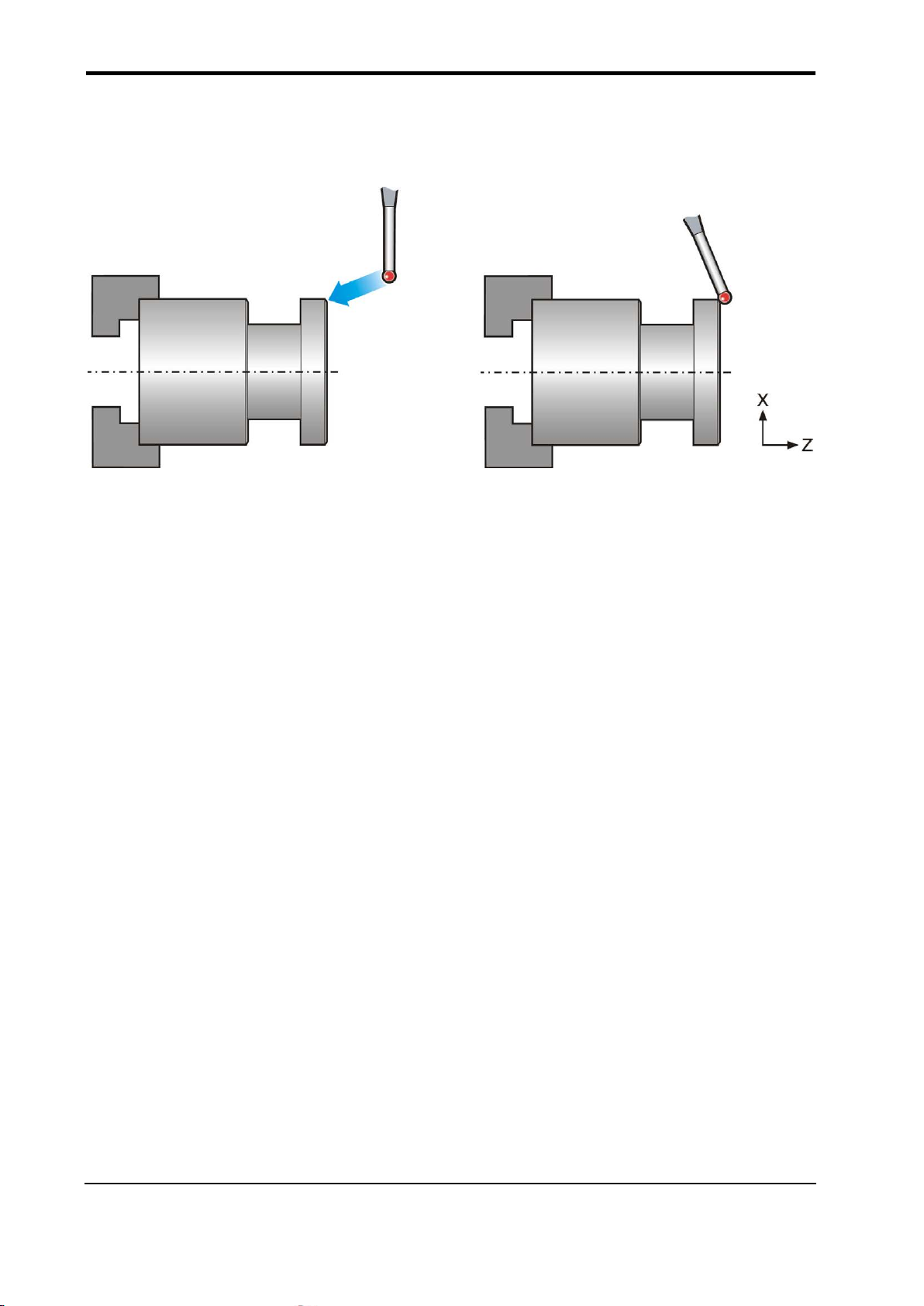
Probe protect ed positioning (probe vertical) – O9610
Figure 4.1 Probe pro tected positioning (probe vertical)
Description
It is important to protect the probe’s stylus against damage should it collide with an
obstacle as the probe moves around the workpiece. When this cycle is used, the machine
will stop in the event of a collision.
Application
The probe is selected and moved to a safe plane. At this point the probe is made active. It
then moves to a measuring position using this macro call.
In the event of a collision the machine will stop. Either a PATH OBSTRUCTED alarm is
generated or error flag #148 is set (see the Mm input).
Format
G65 P9610 Xx and/or Zz [ Ff Mm ]
where [ ] denote optional inputs.
Example: G65 P9610 Z10. F3000. M1.
Publication No. H-2000-6021
Page 29

Protected positioning cycles (probe vertical) 4-3
Xx
x =
The target diameter position for the probe positioning move.
and/or
Zz
z =
The target position for the probe positioning move.
#148 = 7 Probe triggered.
Proprietary G and M codes.
T???
Select the probe.
M??
Switch on the probe.
G65P9610Z-10.X30.F3000
Protected positioning move.
G65P9611X20.T3.
Single surface measure.
M??
Switch off the probe.
Compulsory inputs
Optional inputs
Ff f = The modal feedrate for all protected positioning moves.
The feedrate will be modal to this macro and subsequent feedrate
calls are unnecessary unless a change of feedrate is required. The
maximum safe fast feedrate established during installation must not
be exceeded.
M1. This will set a probe trigger flag (but with no PATH OBSTRUCTED
alarm).
Example
#148 = 0 No probe trigger.
Publication No. H-2000-6021
Page 30
4-4 Protected positioning cycles (probe horizontal)
Xx
x =
The target diameter position for the probe positioning move.
and/or
Zz
z =
The target position for the probe positioning move.
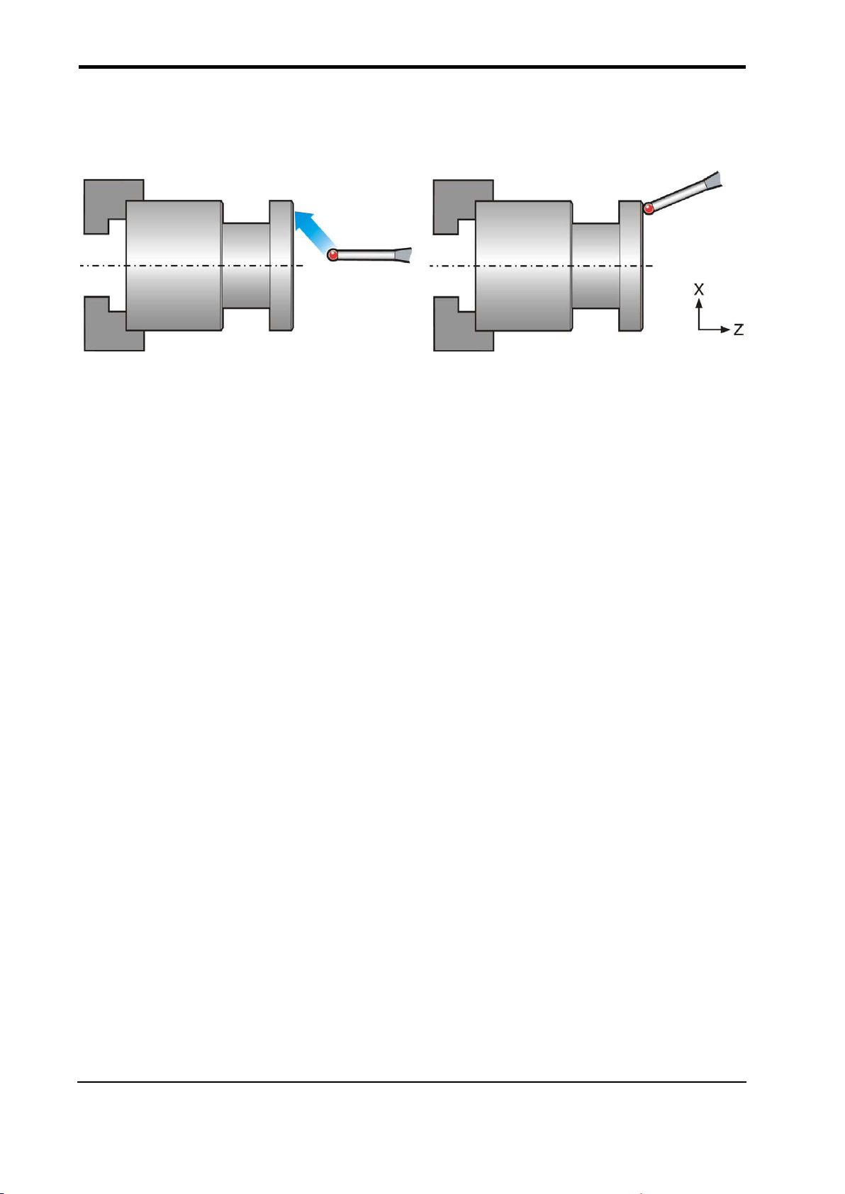
Probe protect ed positioning (probe horizontal) – O9810
Figure 4.2 Probe pro tected positioning (probe horizontal)
Description
It is important to protect the probe’s stylus against damage should it collide with an
obstacle as the probe moves around the workpiece. When this cycle is used, the machine
will stop in the event of a collision.
Application
The probe is selected and moved to a safe plane. At this point the probe is made active. It
then moves to a measuring position using this macro call.
In the event of a collision, the machine will stop. Either a PATH OBSTRUCTED alarm is
generated or error flag #148 is set (see the Mm input).
Format
G65 P9810 Xx and/or Zz [ Ff Mm ]
where [ ] denote optional inputs.
Example: G65 P9810 Z10. F3000. M1.
Compulsory inputs
Publication No. H-2000-6021
Page 31

Protected positioning cycles (probe horizontal) 4-5
be exceeded.
#148 = 7 Probe triggered.
Optional inputs
Ff f = The modal feedrate for all protected positioning moves.
The feedrate will be modal to this macro and subsequent feedrate
calls are unnecessary unless a change of feedrate is required. The
maximum safe fast feedrate established during installation must not
M1. This will set a probe trigger flag (but with no PATH OBSTRUCTED
alarm).
#148 = 0 No probe trigger.
Example
Proprietary G and M codes.
T??? Select the probe.
M?? Switch on the probe.
G65P9810X30.Z-10.F3000 Protected positioning move.
G65P9811X20.T8 Single surface measure.
M?? Switch off the probe.
Publication No. H-2000-6021
Page 32

4-6 Protected positioning cycles (probe horizontal)
This page is intentionally left blank.
Publication No. H-2000-6021
Page 33

Calibrating the probe 5-1
Chapter 5
Calibrating the probe
Before a probe and stylus are used, they must be calibrated correctly. Only when they
have been calibrated acc urately can you achieve total qualit y control ov er your
manufacturing process.
This chapter explains why it is so important that the probe and stylus are calibrated and
then describes how to use the macros that are provided to calibrate them.
Contained in this chapter
Why calibrate a probe and stylus? ................................................................................... 5-2
Single-sided calibration .................................................................................................... 5-2
Double-sided calibration .................................................................................................. 5-3
Calibrating the probe length ............................................................................................. 5-3
Calibration cycles ............................................................................................................. 5-3
Calibrating the probe length (probe vertical) – O9601..................................................... 5-5
Calibrating the stylus Z tool offset double-sided (probe vertical) – O9602 ...................... 5-7
Calibrating the stylus ball radius double-sided (probe vertical) – O9603 ........................ 5-9
Calibrating the stylus single-sided (probe vertical) – O9604 ......................................... 5-11
Calibrating the probe length (probe horizontal) – O9801 .............................................. 5-13
Calibrating the stylus X tool offset double-sided (probe horizontal) – O9802 ............... 5-15
Calibrating the stylus ball radius double-sided (probe horizontal) – O9803 .................. 5-17
Calibrating the stylus single-sided (probe horizontal) – O9804 ..................................... 5-19
Publication No. H-2000-6021
Page 34

5-2 Calibrating the probe
Why calibrate a pro b e and stylus?
When you fit a probe into the machine’s shank/holder it is not necessary for the probe’s
stylus to run true to the spindle centre line. A small amount of run-out can be tolerated.
However, it is good practice to mechanically adjust the stylus so that it is true to the
virtual Y axis. This helps reduce the effects of cosine errors when measuring different
sizes.
Calibrating the probe and stylus ensures that run-out is automatically accounted for.
Without calibration, run-out will lead to inaccurate results.
It is important that you calibrate the stylus of a Renishaw inspection probe in the following
circumstances:
When a probe and stylus are to be used for the first time.
When a new stylus is fitted to the probe.
When it is suspected that the stylus has become distorted or that the probe has
crashed.
At regular intervals to compensate for mechanical changes of your lathe.
Three different operations are used to calibrate a stylus. They are:
Calibrating single-sided.
Calibrating double-sided.
Calibrating the probe length.
Single-sided calibration
Single-sided calibration determines the error value for the stylus ball in relation to a
known surface. This value is stored in the tool wear offset and is used automatically in the
measuring cycles.
NOTE: Only one edge of the stylus is calibrated. Therefore, all subsequent measuring
cycles must use only this calibrated edge.
Publication No. H-2000-6021
Page 35

Calibrating the probe 5-3
Double-sided calibration
Double-sided calibration determines the stylus offset and the radius of the stylus ball. The
offset is stored in the tool wear offset while the radius is stored in a macro variable. Both
values are used automatically in the measuring cycles.
NOTE: Both edges of the stylus are calibrated. Therefore, measuring cycles that use
both sides of the stylus can be used.
Calibrating the probe length
Calibrating a probe on a known reference surface determines the length of the probe,
based on the electronic trigger point. The stored value for length is different from the
physical length of the probe assembly.
Additionally, the operation can automatically compensate for machine and fixture height
errors by adjusting the length value of the probe that is stored.
Calibration cycles
Eight calibration cycles are provided with the Inspection software. Four are for calibrating
a probe positioned vertically and four are for calibrating a probe positioned horizontally.
They may be used in conjunction with one another for complete calibration of the probe.
The purpose of each macro is summarised below.
Macros O9601 and O9801 Used to establish the length of the probe in the tool
Macros O9602 and O9802 Used to establish the stylus offset (for double-sided
Macros O9603 and O9803 Used to establish the radius values of the stylus ball (for
Macros O9604 and O9804 Used to establish the error value of the st ylus ball (for
shank.
calibration only).
double-sided calibration only).
single-sided calibration only).
For complete calibration of a probe system, use the macros as follows:
For double-sided calibration of a vertica ll y mounted probe, use macros O9601,
O9602 and O9603.
For double-sided calibration of a horizontally-mounted probe, use macros O9801,
O9802 and O9803.
Publication No. H-2000-6021
Page 36

5-4 Calibrating the probe
For single-sided calibration of a vertically mounted probe, use macros O9601 and
O9604.
For single-sided calibration of a horizontally-mounted probe, use macros O9801
and O9804.
The Renishaw calibration cycles are split into separate cycles for flexibility.
Publication No. H-2000-6021
Page 37

Calibrating the probe (probe vertical) 5-5
Tt
Calibrating the probe length (probe vertical) – O9601
Tool offset
Xx
reference
size
Figure 5.1 Calibrating the probe length (probe vertical)
Description
The probe is positioned adjacent to an X-axis reference surface. When the calibration
cycle is completed the active tool offset is adjusted to the reference surface.
Application
An approximate tool offset is loaded. The probe is positioned adjacent to the reference
surface.
When the cycle is run, the surface is measured and the tool offset is reset to a new value.
The probe is then returned to the start position.
Format
G65 P9601 Xx Tt
Example: G65 P9601 X50. T20
Publication No. H-2000-6021
Page 38

5-6 Calibrating the probe (probe vertical)
Tt
t =
The active tool offset number.
Xx
x =
The size of the reference surface.
O0001
Proprietary G and M codes
T0101
Select the probe.
M??
Switch on the probe.
G65P9610X60.F3000
Protected positioning move.
G65P9601X50.T1
Calibrate in the X direction and update tool offset 1.
G65P9610X100.
Protected positioning move.
M??
Switch off the probe.
Compulsory inputs
Outputs
The active tool offset is set.
Example: Probe length calibration
Publication No. H-2000-6021
Page 39

Calibrating the probe (probe vertical) 5-7
Tt
t =
The tool offset number that will be updated.
Zz
x =
The nominal size of the feature.
A
B
Calibrating the stylus Z tool offset double-sided (probe vertical) – O9602
Figure 5.2 Calibrating the stylus Z tool offset
double-sided (probe vertical)
Description
Before the cycle is run, the probe is positioned either above a pre-machined web (A) or
inside a pre-machined groove (B). When the cycle is completed, the tool offset is set to
the centre of the stylus in the Z axis.
Application
Pre-machine either a web or a groove with a suitable tool so that the exact centre of the
feature is known. Position the probe to the centre of the web or groove.
When the cycle is run, two measuring moves are made to determine the Z offset of the
stylus. The probe is then returned to the start position.
Format
G65 P9602 Zz Tt [ Rr Xx ]
where [ ] denote optional inputs.
Example: G65 P9602 Z50.005 T8. X50.
Compulsory inputs
Publication No. H-2000-6021
Page 40

5-8 Calibrating the probe (probe vertical)
feature. If this is omitted, a groove cycle is assumed.
O0002
T0101
Select the probe.
M??
Switch on the probe.
G54
Select the work offset.
G65P9610Z-20.F3000
Protected positioning move over the groove.
G65P9610X20.
Protected positioning move into the groove.
G65P9602Z50.T1
Calibrate in a 50 mm (1.97 in) groove and update tool offset 1.
G65P9610X100.
Protected positioning move retract to 100 mm (3.94 in).
M??
Switch off the probe.
M30
End of the program.
Optional input
Xx x = The absolute X-axis measuring position when calibrating on an external
For the Rr optional input, see Chapter 2, "Optional inputs".
Outputs
The Z tool offset will be updated to the centre of the stylus.
Example: Calibrating the stylus Z offset
Run a complete positioning and calibration program as follows.
Set the exact X and Z feature positions in a work offset (for example, using G54).
Publication No. H-2000-6021
Page 41

Calibrating the probe (probe vertical) 5-9
Zz
z =
The nominal size of the reference web or groove.
A
B
Calibrating the stylus ball radius double-sided (probe vertical) – O9603
Figure 5.3 Calibrating the stylus ball radius
double-sided (probe vertical)
Description
Before the cycle is run, the probe is positioned either a bov e a pre-machined web (A) or
inside a pre-machined groove (B). When the cycle is completed, the radius values of the
stylus ball are stored.
Application
The probe to be calibrated is positioned either above the web or inside the groove of
known size. The position of the web or groove is not critical.
When the cycle is run, two moves are made to determine the radius values of the stylus
ball. The probe is then returned to the start position.
Format
G65 P9603 Zz [ Rr Xx ]
where [ ] denote optional inputs.
Example: G65 P9603 Z50.005 X50.
Compulsory input
Publication No. H-2000-6021
Page 42

5-10 Calibrating the probe (probe vertical)
feature. If this is omitted, a groove cycle is assumed.
O0004
T0101
Select the probe.
G54
Select the work offset.
M??
Switch on the probe.
G65P9610Z-20.F3000
Protected positioning move over the groove.
G65P9610X20.
Protected positioning move into the groove.
G65P9603Z15.001
Calibrate in a 15.001 mm (0.5905 in) groove.
G65P9610X100.
Protected positioning move retract to 100 mm (3.94 in).
M??
Switch off the probe.
M30
End of the program.
Optional input
Xx x = The absolute X-axis measuring position when calibrating on an external
For the Rr optional input, see Chapter 2, "Optional inputs".
Outputs
The following data will be stored:
#503 Stylus ball radius in Z.
NOTE: The actual variable is dependent on #112 that is set in O9724.
Example: Calibrating the radius of a stylus ball
Run a complete positioning and calibration program as follows.
Set the approximate X and Z feature positions in a work offset (for example, using G54).
Publication No. H-2000-6021
Page 43

Calibrating the probe (probe vertical) 5-11
A
B
OR
Calibrating the stylus single-sided (probe vertical) – O9604
NOTE: When this method is used for calibrating a stylus, only the calibrated edge of the
stylus must be used in subsequent measuring cycles.
Figure 5.4 Calibrating the stylus single-sided (probe vertical)
Description
Before the cycle is run, the probe is positioned adjacent to a Z axis reference surface.
When the cycle is completed, the active probe tool offset is adjusted to the reference
surface.
Application
An approximate tool offset is loaded. The probe is positioned adjacent to the reference
surface.
When the cycle is run, the surface is measured and the tool offset is reset to a new value.
The probe is then returned to the start position.
Format
G65 P9604 Zz Tt
Example: G65 P9604 Z0. T1.
Compulsory inputs
Tt t = The active tool offset number.
Zz z = The position of the reference surface.
Publication No. H-2000-6021
Page 44

5-12 Calibrating the probe (probe vertical)
O0002
T0101
Select the probe.
M??
Switch on the probe.
G54
Select the work offset.
G65P9610Z10.F3000
Protected positioning move.
G65P9610X20.
Protected positioning move.
G65P9604Z0.T1
Calibrate in the Z direction and update tool offset 1.
G65P9610X100.
Protected positioning move retract to 100 mm (3.94 in).
M??
Switch off the probe.
M30
End of the program.
Outputs
The Z tool offset will be updated to the edge of the stylus.
Example: Calibrating a stylus edge
Run a complete positioning and calibration program as follows.
Set the exact X and Z feature positions in a work offset (for example, using G54).
Publication No. H-2000-6021
Page 45

Calibrating the probe (probe horizontal) 5-13
Tt tool offset
Zz reference height
Calibrating the probe length (probe horizontal) – O9801
Figure 5.5 Calibrating the probe length
(probe horizontal)
Description
The probe is positioned adjacent to a Z-axis reference surface for calibration. When the
cycle is completed, the active probe tool offset is adjusted to the reference surface.
Application
An approximate tool offset is loaded. The probe should be positioned adjacent to the
reference surface.
When the cycle is run, the surface is measured and the tool offset is reset to a new value.
The probe is then returned to the start position.
Format
G65 P9801 Zz Tt
Example: G65 P9801 Z–10. T20
Publication No. H-2000-6021
Compulsory inputs
Tt t = The active tool offset number.
Zz z = The position of the reference surface.
Page 46

5-14 Calibrating the probe (probe horizontal)
O0001
T0101
Select the probe.
G54
Select the work offset.
M??
Switch on the probe.
G65P9810Z10.F3000
Protected positioning move.
G65P9801Z-10.T1
Calibrate in the Z direction and update tool offset 1.
G65P9810Z100.
Protected positioning move.
M??
Switch off the probe.
M30
End of the program.
Outputs
The active tool offset is set.
Example: Probe length calibration
Publication No. H-2000-6021
Page 47

Calibrating the probe (probe horizontal) 5-15
Calibrating the stylus X tool offset double-sided (probe horizontal) – O9802
Figure 5.6 Calibrating the stylus X tool o ffset
double-sided (probe horizontal)
Description
Before the cycle is run, the probe is positioned in front of the diameter (A) or inside the
bore (B). When this cycle is completed, the centre of the stylus is updated to the tool
offset.
Application
Pre-machine either a hole with a suitable boring bar or a diameter with a turning tool.
Position the probe as described above.
When the cycle is run, two measuring moves are made to determine the X offset of the
stylus. The probe is then returned to the start position.
Format
G65 P9802 Xx Tt [ Rr Zz ]
where [ ] denote opti ona l i nputs.
Example: G65 P9802 X50.005 T8. Z50.
Publication No. H-2000-6021
Page 48

5-16 Calibrating the probe (probe horizontal)
Tt
t =
The tool offset number that will be updated.
Xx
x =
The nominal size of the feature.
feature. If this is omitted, a bore cycle is assumed.
O0002
T0101
Select the probe.
M??
Switch on the probe.
G65P9810X0.Z10.F3000
Protected positioning move over the hole.
G65P9810Z–5.
Protected positioning move into the hole.
update tool offset 1.
G65P9810Z100.
Protected positioning move retract to 100 mm (3.94 in).
M??
Switch off the probe.
M30
End of the program.
Compulsory inputs
Optional input
Zz z = The absolute Z-axis measuring position when calibrating on an external
For the Rr optional input, see Chapter 2, "Optional inputs".
Outputs
The X tool offset will be updated to the centre of the stylus.
Example: Calibrating the stylus X offset
Run a complete positioning and calibration program as follows.
Set the exact X and Z feature positions in a work offset (for example, using G54).
G65P9802X50.T1 Calibrate in a 50 mm (1.97 in) diameter bored hole and
Publication No. H-2000-6021
Page 49

Calibrating the probe (probe horizontal) 5-17
Calibrating the stylus ball radius double-sided (probe horizontal) – O9803
Figure 5.7 Calibrating the stylus ball radius
double-sided (probe horizontal)
Description
Before the cycle is run, the probe is positioned either in front of the diameter (A) or inside
the bore (B). When the cycle is completed, the stylus centre is updated to the tool offset.
Application
Pre-machine either a hole with a suitable boring bar or a diameter with a turning tool.
Position the probe as described above.
When the cycle is run, two measuring moves are made to determine the X radius values
of the stylus ball. The probe is then returned to the start position.
Format
G65 P9803 Xx [ Rr Zz ]
where [ ] denote optional inputs.
Example: G65 P9803 X50.005 Z50.
Publication No. H-2000-6021
Page 50

5-18 Calibrating the probe (probe horizontal)
Xx
x =
The nominal size of the feature.
feature. If this is omitted, a ring gauge cycle is assumed.
O0004
T0101
Select the probe.
M??
Switch on the probe.
G65P9810X0.Z10.F3000
Protected positioning move over the hole.
G65P9810Z–5.
Protected positioning move into the hole.
G65P9803X50.001
Calibrate in a 50.001 mm (1.9685 in) diameter ring gauge.
G65P9810Z100.
Protected positioning move retract to 100 mm (3.94 in).
M??
Switch off the probe.
M30
End of the program.
Compulsory input
Optional input
Zz z = The absolute Z-axis measuring position when calibrating on an external
For the Rr optional input, see Chapter 2, "Optional inputs".
Outputs
The following data will be stored:
#500 Stylus ball radius in X (XRAD)
NOTE: The actual variable is dependent on #111 that is set in O9724.
Example: Calibrating the radius of a stylus ball
Run a complete positioning and calibration program as follows.
Set the approximate X and Z feature positions in a work offset (for example, using G54).
Publication No. H-2000-6021
Page 51

Calibrating the probe (probe horizontal) 5-19
Tt
t =
The active tool offset number.
OR
Calibrating the stylus single-sided (probe horizontal) – O9804
NOTE: When this method is used for calibrating a stylus, only the calibrated edge of the
stylus must be used in subsequent measuring cycles.
Figure 5.8 Calibrating the stylus single-sided (probe horizontal)
Description
Before the cycle is run, the probe is positioned either above a diameter (A) or inside a
diameter (B). When the cycle is completed, the edge of the stylus is updated to the tool
offset.
Application
Pre-machine either a hole with a suitable boring bar or a diameter with a turning tool.
Position the probe as described above and run the cycle.
When the cycle is run, a measuring move is made to determine the X offset of the stylus.
The probe is then returned to the start position.
Format
G65 P9804 Xx Tt
Example: G65 P9804 X50.005 T8.
Publication No. H-2000-6021
Compulsory inputs
Xx x = The nominal diameter of the feature.
Page 52

5-20 Calibrating the probe (probe horizontal)
O0002
T0808
Select the probe.
M??
Switch on the probe.
G65P9810X50.Z-6.F3000
Protected positioning move over the hole.
tool offset 8.
G65P9810Z100.
Protected positioning move retract to 100 mm (3.94 in).
M??
Switch off the probe.
M30
End of the program.
Outputs
The X tool offset will be updated to the edge of the stylus.
Example: Single-sided stylus calibration
Run a complete positioning and calibration program as follows.
Set the exact X and Z feature positions in a work offset (for example, using G54).
G65P9804X40.T8 Calibrate against a 40 mm (1.57 in) diameter and update
Publication No. H-2000-6021
Page 53

Standard measuring cycles 6-1
Chapter 6
Standard measuring cycles
This chapter describes how to use the non-vector measuring cycles with verticallymounted and horizontally-mounted probes.
Contained in this chapter
XZ single surface measurement (probe vertical) – O9611 .............................................. 6-2
Web/pocket measurement (probe vertical) – O9612 ....................................................... 6-5
XZ single surface measurement (probe horizontal) – O9811 .......................................... 6-8
Web/pocket measurement (probe horizontal) – O9812 ................................................. 6-11
Publication No. H-2000-6021
Page 54
6-2 Standard measuring cycles (probe vertical)
Xx
x =
The size of the target surface.
or
Zz
z =
The position of the target surface.
XZ single surface measurement (probe vertical) – O9611
Figure 6.1 Measurement of a single surface (probe vertical)
Description
This cycle measures a surface to establish the size or position.
Application
The probe, with its tool offset active, should be positioned adjacent to the surface. The
cycle measures the surface and returns to the start position.
There are two possibilities, as follows:
1. The surface can be treated as a size, where the tool offset is updated in conjunction
with the Tt and the Hh input.
2. The surface can be treated as a reference surface position, for the purpose of
adjusting a work offset using the Ss and Mm inputs.
Format
G65 P9611 Xx or Zz [ Cc Ee Ff Hh Ii Qq Ss Tt Uu Vv Ww ]
where [ ] denote optional inputs.
Example: G65 P9611 X50. C1. E90. F0.8 H0.2 I0.5 Q10. S1. T20. U.5 V.5 W2.
Compulsory inputs
Publication No. H-2000-6021
Page 55

Standard measuring cycles (probe vertical) 6-3
Cc
c = 1.
Takes the error from the reference diameter and stores it in #134.
diameter.
Ii
i =
This is the maximum tolerance used with the C input.
Chuck
C = 1
C = 2
1
2 3 4 5 6 7
Optional inputs
Inputs Cc and Ii are used with the reference touch option. This option eliminates thermal
growth errors from within the probe results, helping to maintain measuring accuracy.
For other optional inputs, see Chapter 2, "Optional inputs".
c = 2.
Takes the error stored in #134 and adds it to the results of the measured
Figure 6.2 Reference touch option
Example: X and Z single surface measurement
Publication No. H-2000-6021
Figure 6.3 Probe movements
Page 56

6-4 Standard measuring cycles (probe vertical)
T???? Select the probe.
M?? Switch on the probe.
1. G65P9610X50.Z10.F3000 Protected positioning move to the start position.
2. G65P9610X15. Protected positioning move.
3. G65P9611Z0.T2 Single surface measure.
4. G65P9610X80. Protected positioning move.
5. G65P9610Z–6. Protected positioning move.
6. G65P9611X40.T4 Single surface measure.
7. G65P9610X100. Protected positioning move.
M?? Switch off the probe.
continue
Tool offset 2 (Z wear) and tool offset 4 (X wear) will be updated.
Publication No. H-2000-6021
Page 57

Standard measuring cycles (probe vertical) 6-5
Web/pocket measurement (probe vertical) – O9612
NOTE: This cycle must not be used unless double-sided calibration has taken place.
Figure 6.4 Measurement of a web or pocket feature (probe vertical)
Description
This cycle measures a web or pocket feature. It uses two measuring moves along the
Z axis.
Application
Position the probe to the expected centre line of the feature and at a suitable position in
the X axis with the probe and probe offset active. Run the cycle with suitable inputs as
described.
Format
G65 P9612 Zz [ Ee Ff Hh Mm Qq Rr Ss Tt Uu Vv Ww ]
or
G65 P9612 Xx Zz [ Ee Ff Hh Mm Qq Rr Ss Tt Uu Vv Ww ]
where [ ] denote optional inputs.
Example: G65 P9612 X50. Z100. E91 F0.8 H0.2 M.2 Q10. R10. S1. T20. U.5 V.5 W2.
Publication No. H-2000-6021
Page 58

6-6 Standard measuring cycles (probe vertical)
omitted, a pocket cycle is assumed.
Zz
z =
The nominal size of the feature when measured in the Z axis.
G54
T?????
Select the probe.
M??
Switch on the probe.
1.
G65P9610Z20.X60.F3000
Protected positioning move.
2.
G65P9610Z0.
Protected positioning move.
3. and 4.
G65P9612X40.Z10.S2
Measure a 10.0 mm (1.968 in) wide web.
1 2 3
4
5
Compulsory inputs
Xx x = The absolute X-axis position when measuring a web feature. If this is
Optional inputs
See Chapter 2, "Optional inputs".
Outputs
See Chapter 3, "Variable outputs".
Example 1: Measuring a web
Figure 6.5 Probe movements
Publication No. H-2000-6021
Page 59

Standard measuring cycles (probe vertical) 6-7
G54
T?????
Select the probe.
M??
Switch on the probe.
1.
G65P9610X100.Z20.F3000
Protected positioning move.
2.
G65P9610Z–20.
Protected positioning move.
3.
G65P9610X40.
Protected positioning move.
4.
G65P9612Z10.S2
Measure a 10.0 mm (1.181 in) wide pocket.
5.
G65P9610X100.
Protected positioning move.
M??
Switch off the probe.
continue
1
2
3 4 5
5. G65P9610X100. Protected positioning move.
M?? Switch off the probe.
continue
The centre line of the feature in the X axis is stored in the work offset 02 (G55).
Example 2: Measuring a pocket (referred datum)
Figure 6.6 Probe movements
The error of the centre line is referred to the datum point Z0 and the revised Z0 position is
set in work offset 02 (G55).
Publication No. H-2000-6021
Page 60

6-8 Standard measuring cycles (probe horizontal)
Xx
x =
The size of the target surface.
or
Zz
z =
The position of the target surface.
XZ single surface measurement (probe horizontal) – O9811
Figure 6.7 Measurement of a single surface (probe horizontal)
Description
This cycle measures a surface to establish the size or position.
Application
The probe, with its tool offset active, should be positioned adjacent to the surface. The
cycle measures the surface and returns to the start position.
There are two possibilities, as follows:
1. The surface can be treated as a size, where the tool offset is updated in conjunction
with the Tt and the Hh input.
2. The surface can be treated as a reference surface position, for the purpose of
adjusting a work offset using the Ss and Mm inputs.
Format
G65 P9811 Xx or Zz [ Cc Ee Ff Hh Ii Qq Ss Tt Uu Vv Ww ]
where [ ] denote optional inputs.
Example: G65 P9811 X50. C1. E90 F0.8 H0.2 I0.5 Q10. S1. T20. U.5 V.5 W2.
Compulsory inputs
Publication No. H-2000-6021
Page 61

Standard measuring cycles (probe horizontal) 6-9
Cc
c = 1.
Takes the error from the reference diameter and stores it in #134.
diameter.
Ii
i =
This is the maximum tolerance used with the C input.
G54
T?????
Select the probe.
Figure 6.8 Reference touch option
Chuck
C = 1
C = 2
1
2 3 4 5 6
7
Optional inputs
Inputs Cc and Ii are used with the reference touch option. This option eliminates thermal
growth errors from within the probe results, helping to maintain measuring accuracy.
c = 2. Takes the error stored in #134 and adds it to the results of the measured
For other optional inputs, see Chapter 2, "Optional inputs".
Example: X and Z single surface measurement
Figure 6.9 Probe movements
Publication No. H-2000-6021
Page 62

6-10 Standard measuring cycles (probe horizontal)
M?? Switch on the probe.
1. G65P9810Z10.F3000 Protected positioning move.
2. G65P9810X20. Protected positioning move to the start position.
3. G65P9811Z0.T2 Single surface measure.
4. G65P9810X80. Protected positioning move.
5. G65P9810Z–20. Protected positioning move.
6. G65P9811X60.T4 Single surface measure.
7. G65P9810X100. Protected positioning move.
M?? Switch off the probe.
continue
Tool offset 2 (Z wear) and tool offset 4 (X wear) will be updated.
Publication No. H-2000-6021
Page 63

Standard measuring cycles (probe horizontal) 6-11
Web/pocket measurement (probe horizontal) – O9812
NOTE: This cycle must not be used unless double-sided calibration has taken place.
Figure 6.10 Measurement of a web or pocket feature (probe horizontal)
Description
This cycle measures a web or pocket feature. It uses two measuring moves along the X axis.
Application
Position the probe to the expected centre line of the feature and at a suitable position in
the Z axis with the probe and probe offset active. Run the cycle with suitable inputs as
described.
Format
G65 P9812 Xx [ Ee Ff Hh Mm Qq Rr Ss Tt Uu Vv Ww ]
or
G65 P9812 Xx Zz [ Ee Ff Hh Mm Qq Rr Ss Tt Uu Vv Ww ]
where [ ] denote optional inputs.
Example: G65 P9812 X50. Z100. E92 F0.8 H0.2 M.2 Q10. R10. S1. T20. U.5 V.5 W2.
Publication No. H-2000-6021
Page 64

6-12 Standard measuring cycles (probe horizontal)
Xx
x =
The nominal size of the feature.
or
omitted, a pocket cycle is assumed.
1
2 3 4
5
6
7
Compulsory inputs
Zz z = The absolute Z-axis position when measuring a web feature. If this is
Optional inputs
See Chapter 2, "Optional inputs".
Outputs
See Chapter 3, "Variable outputs".
Example 1: Measuring a web
Figure 6.11 Probe movements
G54
T????? Select the probe.
M?? Switch on the probe.
G65P9810.Z10.F3000 Protected positioning move.
1. G65P9810X0. Protected positioning move.
2 to 7. G65P9812X50.Z–10.S2 Measure a 50.0 mm (1.968 in) wide web.
G65P9810Z10. Protected positioning move.
Publication No. H-2000-6021
Page 65

Standard measuring cycles (probe horizontal) 6-13
T?????
Select the probe.
M??
Switch on the probe.
1.
G65P9810Z10.F3000
Protected positioning move.
2.
G65P9810Z-10.
Protected positioning move.
3.
G65P9812X30.S2
Measure a 30.0 mm (1.181 in) wide pocket.
G65P9810Z10.
Protected positioning move.
M??
Switch off the probe.
continue
1
2
3
M?? Switch off the probe.
continue
The centre line of the feature in the X axis is stored in work offset 02 (G55).
Example 2: Measuring a pocket
Figure 6.12 Probe movements
The centre line of the feature in the X axis is stored in work offset 02 (G55).
Publication No. H-2000-6021
Page 66

6-14 Standard measuring cycles (probe horizontal)
This page is intentionally left blank.
Publication No. H-2000-6021
Page 67

Additional cycles 7-1
Chapter 7
Additional cycles
The Inspection software contains four macro cycles that cannot be described under the
headings used in previous chapters (see chapters 4 to 6 inclusive). This chapter
describes how to use these cycles.
Contained in this chapter
Storing multi-stylus data (probe vertical) – O9630 ........................................................... 7-2
Loading multi-stylus data (probe vertical) – O9631.......................................................... 7-4
Storing multi-stylus data (probe horizontal) – O9830 ....................................................... 7-6
Loading multi-stylus data (probe horizontal) – O9831 ..................................................... 7-8
Publication No. H-2000-6021
Page 68

7-2 Additional cycles (probe vertical)
K1
K2
Probe 1
Probe 2
Storing multi-s tylus data (probe vertical) – O9630
Calibration data
Figure 7.1 Storing multi-stylus data (probe vertical)
Calibration data
Description
The macro is used to store the stylus calibration data that is established during the
calibration cycles. The data is stored in a spare set of macro variables.
Stored data for each probe can be recalled using macro O9631.
Application
Calibrate the stylus using macros O9602 and O9603. Run macro O9630 to store the
calibration data #503. The values are recalled when macro O9631 is run.
NOTE: All # numbers shown are with the base number set to 503 in O9524.
Format
G65 P9630 Kk
Example: G65 P9630 K1.
Publication No. H-2000-6021
Page 69

Additional cycles (probe vertical) 7-3
O0003
G54
M??
Switch on the probe.
G65P9610X5.F3000
Protected positioning move for X.
G65P9603Z50.001
Calibrate in a reference feature (a ring gauge).
G65P9630K1.
Store calibration values for multi-stylus K1.
G65P9610X100.
Protected positioning move.
M??
Switch off the probe.
M30
End of the program.
Compulsory input
Kk k = This is the multi-stylus probe number that is used for storing calibration
data.
The active calibration data is stored in the macro variables shown in the
following table. The actual variables used are dependent on the #112
setting in O9524.
Active data K1 K2
Ball radius Z #503 #504 #505
NOTE: Spare macro variable locations, in which the calibration data can be stored, are
dependent on the machine options available and the variables that are already used by
your programs. These can be moved, depending on the #112 setting in O9524.
Example: Multi-stylus store K1
Publication No. H-2000-6021
Page 70

7-4 Additional cycles (probe vertical)
Probe 2
K2
Probe 1
K1
Loading multi-st ylus data (probe vertical) – O9631
Calibration data
Figure 7.2 Loading multi-stylus data (probe vertical)
Calibration data
Description
This macro is used (in conjunction with O9630) to load stored calibration data for a
specific probe/stylus configuration into the active calibration variable range. It must be run
before using the probe and stylus.
Application
The program must be run immediately before a measuring cycle to select the correct
probe calibration data. The Kk input determines the data that is to be loaded.
NOTE: All # numbers shown are with the base number set to 503 in O9524.
Format
G65 P9631 Kk
Example: G65 P9631 K1.
Publication No. H-2000-6021
Page 71

Additional cycles (probe vertical) 7-5
G54
M??
Switch on the probe.
G65P9610X10.F3000
Protected positioning move.
G65P9631K1.
Load calibration values for multi-stylus K1.
G65P9612Z30.S2
Measure a 30.0 mm (1.181 in) diameter bore.
G65P9610X10.
Protected positioning move.
G65P9610Z350.
Protected positioning move.
M??
Switch off the probe.
continue
Compulsory input
Kk k = This is the multi-stylus probe number that is used for loading stored data.
For a specific probe/stylus configuration, the Kk input number must be
the same as that used when storing the data with O9630.
The active calibration data is stored in the macro variables shown in the
following table. The actual variables used are dependent on the #112
setting in O9524.
Active data K1 K2
Ball radius Z #503 #504 #505
NOTE: Spare macro variable locations, in which the calibration data can be stored, are
dependent on the machine options available and the variables that are already used by
your programs. These can be moved, depending on the #112 setting in O9524.
Example: Multi-stylus load K1
Publication No. H-2000-6021
Page 72

7-6 Additional cycles (probe horizontal)
Probe 2
Probe 1
K2
K1
Storing multi-stylus data (probe horizontal) – O9830
Calibration
data
Calibration
data
Figure 7.3 Storing multi-stylus data (probe horizontal)
Description
This macro is used to store stylus calibration data that is established during the calibration
cycles. The data is stored in a spare set of macro variables.
Stored data for each probe can be recalled using macro O9831.
Application
Calibrate the stylus using macro O9802 and O9803. Run macro O9830 to store the
calibration data #500. The values are recalled when macro O9831 is run.
NOTE: All # numbers shown are with the base number set to 500 in O9724.
Format
G65 P9830 Kk
Example: G65 P9830 K1.
Compulsory input
Kk k = This is the multi-stylus probe number that is used for storing calibration
data.
The active calibration data is stored in the macro variables shown in the
following table. The actual variables used are dependent on the #111
setting in O9724.
Publication No. H-2000-6021
Page 73

Additional cycles (probe horizontal) 7-7
O0003
G54
M??
Switch on the probe.
G65P9810Z-5.F3000
Protected positioning move for Z.
G65P9803X50.001
Calibrate in a reference feature (a ring gauge).
G65P9830K1.
Store calibration values for multi-stylus K1.
G65P9810Z100.
Protected positioning move.
M??
Switch off the probe.
M30
End of the program.
Active data K1 K2
Ball radius X #500 #501 #502
NOTE: Spare macro variable locations, in which the calibration data can be stored, are
dependent on the machine options available and the variables that are already used by
your programs. These can be moved, depending on the #111 setting in O9724.
Example: Multi-stylus store K1
Publication No. H-2000-6021
Page 74

7-8 Additional cycles (probe horizontal)
setting in O9724.
Probe 2
K2
K1
Probe 1
Loading multi-st ylus data (probe horizontal) – O9831
Calibration
data
Calibration
data
Figure 7.4 Loading multi-stylus data (probe horizontal)
Description
This macro is used (in conjunction with O9830) to load stored calibration data for a
specific probe/stylus configuration into the active calibration variable range. It must be run
before using the probe and stylus.
Application
The program must be run immediately before any measuring cycle to select the correct
probe calibration data. The Kk input determines the data that is to be loaded.
NOTE: All # numbers shown are with the base number set to 500 in O9724.
Format
G65 P9831 Kk
Example: G65 P9831 K1.
Compulsory input
Kk k = This is the multi-stylus probe number that is used for loading stored data.
For a specific probe/stylus configuration, the Kk input number must be
the same as that used when storing the data with O9830.
The active calibration data is stored in the macro variables shown in the
following table. The actual variables used are dependent on the #111
Publication No. H-2000-6021
Page 75

Additional cycles (probe horizontal) 7-9
G54
M??
Switch on the probe.
G65P9810Z–10.F3000
Protected positioning move.
G65P9831K1.
Load calibration values for multi-stylus K1.
G65P9812X30.S2
Measure a 30.0 mm (1.181 in) diameter bore.
G65P9810Z10.
Protected positioning move.
G65P9810X350.
Protected positioning move.
M??
Switch off the probe.
Active data K1 K2
Ball radius X #500 #501 #502
NOTE: Spare macro variable locations, in which the calibration data can be stored, are
dependent on the machine options available and the variables that are already used by
your programs. These can be moved, depending on the #111 setting in O9724.
Example: Multi-stylus load K1
Publication No. H-2000-6021
Page 76

7-10 Additional cycles (probe horizontal)
This page is intentionally left blank
Publication No. H-2000-6021
Page 77

C-axis cycles 8-1
Chapter 8
C-axis cycles
This chapter describes how to use the two C-axis macros that are supplied as part of the
Inspection software.
Contained in this chapter
C-axis find (probe vertical) – O9650 ................................................................................ 8-2
C-axis find (probe horizontal) – O9850 ............................................................................ 8-4
Publication No. H-2000-6021
Page 78

8-2 C-axis cycles (probe vertical)
Dd
d =
The linear width of the feature.
Hh
h =
Half the total positional tolerance.
Default: 5 mm.
C-axis find (probe vertical) – O9650
Figure 8.1 C-axis find (probe vertical)
Description
This cycle will take two readings by moving the C axis. External features can also be
measured by moving the X axis. The results can be used to update a work shift.
Application
The stylus must be programmed to a start position that is either above an external feature
or inside an internal feature. The C axis must be engaged before calling up the cycle.
The inclusion of an Xx input indicates that an external feature is to be measured.
Format
G65 P9650 Dd [ Xx Qq Rr Hh Ss ]
where [ ] denote optional inputs.
Example: G65 P9650 D20. X10. Q10. R10. H0.2 S1.
Compulsory input
Optional inputs
Qq q = The amount of scan past the nominal surface position and the clearance
for external features.
Publication No. H-2000-6021
Page 79

C-axis cycles (probe vertical) 8-3
Default:
Bore size = 20.0
X position = X60.0
X100.0Z20.0C0
Move to the safe position.
G65P9610Z–40.0
Move over the bore.
G65P9610X60.0
Move into the bore.
G65P9650D20.0
Measure the bore.
G65P9610X100.0
Move out of the bore.
G65P9610Z20.0
Move to the start position.
Rr r = The clearance move amount in C for an external feature only (angle
value).
5 mm plus the ball radius converted into an angle.
Xx x = The absolute X position at which a reading is taken when measuring a
external feature.
For the Ss optional input, see Chapter 2, “Optional inputs”.
Example: Bore
Z position = Z–40.0
Publication No. H-2000-6021
Page 80

8-4 C-axis cycles (probe horizontal)
Dd
d =
The linear width of the feature.
Hh
h =
Half the total positional tolerance.
Default: 10°.
C-axis find (probe horizontal) – O9850
Figure 8.2 C-axis find (probe horizontal)
Description
This cycle will take two readings by moving the C axis. External features can also be
measured by moving the Z axis. The results can be used to update a work shift.
Application
The stylus must be programmed to a start position that is either above an external feature
or inside an internal feature. The C axis must be engaged before calling up the cycle.
The inclusion of a Zz input indicates that an external feature is to be measured.
Format
G65 P9850 Dd [ Zz Qq Rr Hh Ss ]
where [ ] denote optional inputs.
Example: G65 P9850 D20. Z10. Q10. R10. H0.2 S1.
Compulsory input
Optional inputs
Qq q = The amount of scan past the nominal surface position and the clearance
for external features.
Publication No. H-2000-6021
Page 81

C-axis cycles (probe horizontal) 8-5
Default:
Bore size = 20.0
X position = X60.0
X100.0Z20.0C0
Move to the safe position.
G65P9810X60.0
Move over the bore.
G65P9810Z–40.0
Move into the bore.
G65P9850D20.0
Measure the bore.
G65P9810Z20.0
Move out of the bore.
Rr r = The clearance move amount in C for an external feature only (angle
value).
5 mm plus the ball radius converted into an angle.
Zz z = The absolute Z position at which a reading is taken when measuring an
external feature.
For the Ss optional input, see Chapter 2, “Optional inputs”.
Example: Bore
Z position = Z–40.0
Publication No. H-2000-6021
Page 82

8-6 C-axis cycles (probe horizontal)
This page is intentionally left blank
Publication No. H-2000-6021
Page 83

Alarms and error messages 9-1
Chapter 9
Alarms and error messages
When an error occurs during use of the Inspection software, an alarm number or
message is generated. This is displayed on the screen of the controller.
This chapter describes the meaning and likely cause of each alarm message that may be
displayed. It then describes typical actions you should take to clear the fault.
Contained in this chapter
General alarms ................................................................................................................ 9-2
Publication No. H-2000-6021
Page 84

9-2 Alarms and error messages
#148 flag
3006=
1 (OUT OF TOLERANCE)
1
1 (OUT OF POSITION)
2
1 DIA OFFSET TOO LARGE
5
continue.
General alarms
Format:
1 (UPPER TOL EXCEEDED) No offset update if the cycle
Action: Press cycle start to continue.
Format: #3000 = 91 (MESSAGE)
(FORMAT ERROR)
(K INPUT MISSING)
(T INPUT MISSING)
(X INPUT MISSING)
(Y INPUT MISSING)
(Z INPUT MISSING)
Updates the offset if the cycle
start button is pressed to
continue.
3
start button is pressed to
(SH INPUT MIXED)
(ST INPUT MIXED)
(TM INPUT MIXED)
(XZ INPUT MIXED)
(K INPUT OUT OF RANGE)
Action: Edit the program and start again from a safe start position.
This is a reset condition.
Format: #3000 = 86 (PATH OBSTRUCTED)
Cause: The probe has made contact with an obstruction. This alarm occurs only
during a protected positioning cycle.
Action: Edit the program. Clear the obstruction and start again from a safe position.
This is a reset condition.
Format: #3000 = 88 (NO FEEDRATE)
Cause: This alarm occurs only during a protected positioning cycle.
Action: Edit the program. Insert the F___ code input and start again from a safe
position.
This is a reset condition.
Publication No. H-2000-6021
Page 85

Alarms and error messages 9-3
Format: #3000 = 92 (PROBE OPEN)
Cause: This alarm occurs if the probe is already triggered before a move.
The stylus may be in contact with a surface or the probe has failed to reseat.
This could be due to swarf trapped around the probe eyelid.
Action: Clear the fault and start again from a safe start position.
This is a reset condition.
Format: #3000 = 93 (PROBE FAIL)
Cause: This alarm occurs if the probe did not trigger during the move.
The surface was not found or the probe has failed.
Action: Edit the program and start again from a safe start position.
This is a reset condition.
Format: #3000 = 94 (C POSITION ERROR)
Cause: The positional error of the feature exceeds the tolerance value (H).
Action: Reload the component and start again from a safe start position.
This is a reset condition.
Format: #3000 = 95 (CHECK SETTINGS #120)
Cause: This alarm occurs if the settings in O9724 are set incorrectly.
Action: Edit the program O9724 with correct values.
Publication No. H-2000-6021
Page 86

9-4 Alarms and error messages
This page is intentionally left blank
Publication No. H-2000-6021
Page 87

Settings, macros and variables 10-1
Chapter 10
Settings, macros and variables
Contained in this chapter
Customising the software ............................................................................................... 10-2
Editing the settings macro (O9524 or O9724) ........................................................ 10-2
Setting #33 .............................................................................................................. 10-3
Variable base number setting (#111 and #112) ...................................................... 10-3
Alarm settings (#110) .............................................................................................. 10-3
Process alarms ....................................................................................................... 10-4
Work offset update tests ................................................................................................ 10-4
Use of macro variables .................................................................................................. 10-4
Local variables ........................................................................................................ 10-4
Common variables .................................................................................................. 10-5
Common retained variables .................................................................................... 10-6
Publication No. H-2000-6021
Page 88

10-2 Settings, macros and variables
#33 = 1 (SET TO 1/2/3/4/5)
See “Setting #33” later in this chapter.
If greater than 64, tool offset = 2.
#112)" later in this chapter.
#112)" later in this chapter.
and should be optimised.
PROBE OPEN or PROBE FAIL message.
Customising the software
Editing the settings macro (O9524 or O9724)
A settings macro (O9524 or O9724) is called at the beginning of each top-level macro to
establish the necessary modal information. If the default values are not suitable, you will
need to change the values during installation by editing this macro.
The following options of macros O9524 and O9724 will need to be set:
Tolerance alarms or flag only (FMS type application).
Tool offset type.
Variable base number.
The examples in this chapter are for general guidance only. Note that the exact
programming format may not suit either your machine set or the recommended method
as specified by your machine builder.
#120 = 1 If less than 64, tool offset = 1.
#111 = 500 See "Variable base number setting (#111 and
#112 = 503 See "Variable base number setting (#111 and
#119 = 5000 (FAST FEED MM)
#119 = 200 (FAST FEED INCH)
NOTES:
1. The Z-axis P9726 basic move macro fast feedrate is at the #119×.6 value
(3000 mm/min as standard).
2. All Z-axis positioning moves are also at the #119×.6 value (3000 mm/min as
standard).
3. All X-axis positioning moves are at the #119 value (5000 mm/min as standard).
The fast feedrate of the cycles can be adjusted by
this variable to suit the machine characteristics
#123 = .05 (POSITION ZONE MM) This is the zone at either the start or end of the
block in which the cycle is aborted with either a
Publication No. H-2000-6021
Page 89

Settings, macros and variables 10-3
Setting #33
It has been found that machine configurations can vary between different machine tool
builders. This means that a modification to #33 may be necessary. To establish whether
#33 needs modifying, carry out the following procedure:
1. Load approximate values into the probe tool offset. This includes entering small
values (0.5 mm [0.019 in]) into the wear columns.
2. Set a work offset to a convenient position.
3. Send the machine to a position that is clear of any obstruction; for example, the
reference point is ideal.
4. Switch on the probe.
5. Run a protected positioning cycle and move to a position at which no collision will
occur.
6. If the cycle completes with no alarm, no edits are required to #33.
If the PROTECTED POSITIONING alarm is issued, edit #33 to the next option then
repeat the procedure.
7. When no alarm occurs, #33 is set correctly.
Variable base number setting (#111 and #112)
The base number defines the first variable in the set of variables used for setting and
calibration data. The default values are 500 (#500) and 503 (#503). A default value may
be changed by editing the settings macro (O9524 or O9724). The base number edit is
found near the top of this macro:
#111 = 500 (EDIT HORIZ BASE NO.)
#112 = 503 (EDIT VERT BASE NO.)
See “Use of macro variables” later in this chapter for a full list of the variables affected.
Before editing, check the availability of the variables.
Alarm settings (#110)
Using #110, the software can be set to operate in either of the following modes:
Stop the machine at the end of the measuring cycle with an alarm message and set
the alarm flag #148.
Set the alarm flag #148 only, allowing the process to continue.
Publication No. H-2000-6021
Page 90

10-4 Settings, macros and variables
set and the cycle continues.
#110 = 0 If one of the conditions ( * ) listed below in “Process
alarms” occurs, the cycle stops with an alarm
message and flag #148 is set as appropriate.
Otherwise flag #148 = 0 is set and the cycle
continues.
#110 = 1
If one of the conditions ( * ) listed below in “Process
alarms” occurs, flag #148 is set as appropriate but
the cycle does not stop. Otherwise flag #148 = 0 is
Process alarms
* No alarm #148 = 0
* Out of tolerance #148 = 1
* Out of position #148 = 2
* Upper tolerance exceeded #148 = 3
* Diameter offset too large #148 = 5
NOTE: If it is necessary to switch this option on and off during the program, then the
following line in macro O9524 or O9724 may be deleted during installation. #110 can then
be programmed.
#110 = 0(SELECT ALARM METHOD).
Work offset update tests
It has been found that machines can be set for either positive or negative work offset
updating. This means that a modification to the software may be necessary. Edit the
following line at the start of macro O9732 and/or O9532.
#30=1(±AXIS UPDATE) Example +1 or –1.
Use of macro variables
Local variables
#1 to #32 These are used within each macro as necessary for calculation etc.
Publication No. H-2000-6021
Page 91

Settings, macros and variables 10-5
(a)
(b)
(c)
X
x
X
#106
1 2 3
Common variables
#100 to #105 Not used by this software package.
#106 Basic move control factor (see Figure 10.1). This is used to control the
back-off distance in the basic move before the final gauge move. It
should be fine-tuned on installation to suit the machine.
A default value of 0.5 is installed by the software. The actual factor
should normally be between 0 and 1.0. Reduce the value to reduce the
back-off distance.
(Basic move
control factor)
Move 1: Fast feed to find the surface. a = Fast feed.
Move 2: Recover off the surface. b = Gauge feed
(30 mm/min).
Move 3: Gauge feed 30 mm/min (1.2 in/min). c = Return.
Figure 10.1 Basic move control factor
#108 Radius or diameter programming.
#109 Target position for C-axis cycles.
#110 Flag or alarm selection (see “Editing the settings macro (O9524 or
O9724)” earlier in this chapter).
#111 Variable base number (probe horizontal).
#112 Variable base number (probe vertical).
#113 Transfer location for C-axis cycles.
#114 Active tool length X axis.
#116 Active tool length Z axis.
#117 Modal feedrate value used in the protected positioning macros (O9610
and O9810).
#118 RADIUS TOO LARGE flag macros O9612 and O9812.
Publication No. H-2000-6021
Page 92

10-6 Settings, macros and variables
#119 Fast feedrate value. This is set in macro O9524 or O9724 at
5000 mm/min (200 in/min) default value.
#120 Setting variable used in macros O9524 and O9724.
#121 Print option. The 6-digit component number is incremented by 1 with
each heading program. To reset, state #121 = 0.
#122 The 4-digit feature number is incremented by 1 with each print macro
call program. To reset, state #122 = 0.
#123 Start and end of block position zone normal setting 0.05 mm
(0.002 in). If the skip position is within this zone, the cycle aborts with
either a PROBE OPEN or PROBE FAIL alarm.
#124 Stored X skip position at the end of the basic move macro O9726.
#125 Stored skip for C-axis cycles.
#126 Stored Z skip position at the end of the basic move macro O9726.
#127 X average skip position at the end of the X diameter move macro
O9721.
#129 Inch/metric multiplier (0.04/1.0).
#130 to #133 Not used by this software.
#134 Error store when using the C1 input macros O9611 and O9811.
#135 to #149 See Chapter 3, "Variable outputs".
#150 onwards Not used by this software.
Common retained variables
The actual common retained variables that are used are determined by the values set in #111
and #112 in the settings macro (O9524 or O9724). Default values are 500 for #111 and 503 for
#112 (see “Variable base number setting (#111 and #112)” earlier in this chapter).
#500 [111+0] (XRAD) X calibration radius (probe horizontal).
#501 [111+1] Multi-stylus storage K1 (probe horizontal).
#502 [111+2] Multi-stylus storage K2 (probe horizontal).
#503 [112+0] (ZRAD) Z calibration radius (probe vertical).
#504 [112+1] Multi-stylus storage K1 (probe vertical).
#505 [112+2] Multi-stylus storage K2 (probe vertical).
Publication No. H-2000-6021
Page 93

General information 11-1
Chapter 11
General information
Contained in this chapter
Tolerances ..................................................................................................................... 11-2
Experience values Ee .................................................................................................... 11-3
Reason for using this option ................................................................................... 11-3
Printing a macro output – an example ........................................................................... 11-3
Publication No. H-2000-6021
Page 94

11-2 General information
Uu
Hh
Vv
b c d e a
Tolerances
Uu, Hh and Vv apply to size and tool offset updates only.
a = Nominal size.
b = Null band. This is the tolerance zone where no tool offset adjustment occurs.
c = Area where the Ff input is effective in percentage feedback. F (0 to 1) gives 0% to 100%
feedback to the tool offset.
d = OUT OF TOLERANCE alarm occurs. The tolerance value that applies to the size of the
feature is defined by input Hh.
e = Uu upper tolerance. If this value is exceeded, no tool offset or work offset is updated
and the cycle stops with an alarm. This tolerance applies to both size and position
where applicable.
Figure 11.1 Size and tool o ffset update tolerances
Publication No. H-2000-6021
Page 95

General information 11-3
Experience values Ee
The measured size can be adjusted by an amount stored in a spare tool offset.
Example:
Measure a 40 mm diameter and update tool offset 20.
G65 P9812 D40. T20 E21 An experience value stored in tool offset 21 will be
added to the measured size.
Reason for using this option
Component clamping forces in some applications can influence the measured size.
Therefore, an adjustment value to relate measurement to a traceable standard, such as a
co-ordinate measuring machine, is desirable. Thermal effects can also be compensated
by this means.
Printing a macro output – an example
-------------------------------------------------------------------------COMPONENT NO 31 FEATURE NO 1
-------------------------------------------------------------------------POSN R79.0569 ACTUAL 79.0012 TOL TP 0.2000 DEV -0.0557
POSN X-45.0000 ACTUAL -45.1525 TOL TP 0.2000 DEV -0.1525
POSN Y-65.0000 ACTUAL -64.8263 TOL TP 0.2000 DEV 0.1737
+++++OUT OF POS+++++ ERROR TP 0.1311 RADIAL
ANG -124.6952 ACTUAL -124.8578 DEV -0.1626
--------------------------------------------------------------------------COMPONENT NO 31 FEATURE NO 2
--------------------------------------------------------------------------SIZE D71.0000 ACTUAL 71.9072 TOL 0.1000 DEV 0.9072
+++++OUT OF TOL+++++ ERROR 0.8072
POSN X-135.0000 ACTUAL -135.3279 DEV -0.3279
POSN Y-65.0000 ACTUAL -63.8201 DEV 1.1799
Publication No. H-2000-6021
Page 96

11-4 General information
This page is intentionally left blank.
Publication No. H-2000-6021
Page 97

Features, cycles and limitations A-1
Appendix A
Features, cycles and limitations
Contained in this appendix
Features of the Inspection software ................................................................................. A-2
Cycles .............................................................................................................................. A-2
Limitations ........................................................................................................................ A-2
Publication No. H-2000-6021
Page 98

A-2 Features, cycles and limitations
Features of the Inspection software
Protected positioning.
Measurement of internal and external features to determine both size and position.
This includes:
Obtaining a hard copy printout of feature data.
Applying tolerances to both size and position.
Additional features for feedback of errors include:
Experience values can be applied to the measured size.
Percentage feedback of the error can be applied.
Null band zone for no tool offset update.
Cycles
Calibration of multiple styli.
Software option to turn off the tolerance alarms and provide a flag-only alarm.
Suitable for FMS and unmanned applications.
Built-in stylus collision and false trigger protection for all cycles.
Diagnostic and format error checking routines for all cycles.
Protected positioning.
Measurement:
XZ single surface.
Web/pocket.
C-axis measurement.
Multi-stylus calibration.
Limitations
The probe cycles will not run if ‘mirror image’ is active.
Consider macro variable availability.
Publication No. H-2000-6021
Page 99

Co-ordinate systems used on lathes B-1
!
Appendix B
Co-ordinate systems used on lathes
Contained in this chapter
Example 1 Tool offset geometry ..................................................................................... B-2
Example 2 Using either G54 to G59 or G50 to define the component zero ................... B-3
G54 to G59 method .................................................................................................. B-3
G50 method setting a program shift to the turret reference position ........................ B-4
Example 3 Using G10 to define the component zero ..................................................... B-5
Example 4 Using either G92 or G50 to define the component zero-to-tool tip
position ......................................................................................................................... B-6
CAUTION: While the examples described in this chapter are commonly used,
you must be aware that they might not be suitable for your machine. Care must be
taken if you change the method of co-ordinate system setting on your machine to one that
is described here.
Publication No. H-2000-6021
Page 100

B-2 Co-ordinate systems used on lathes
a
b
b
a
Example 1 Tool offset geometry
Boring tool
Turning tool
Figure B.1 Example 1
a = the X geometry of the tool (2 × a for diameter type offsets)
b = the Z geometry of the tool
Publication No. H-2000-6021
 Loading...