

Page 1
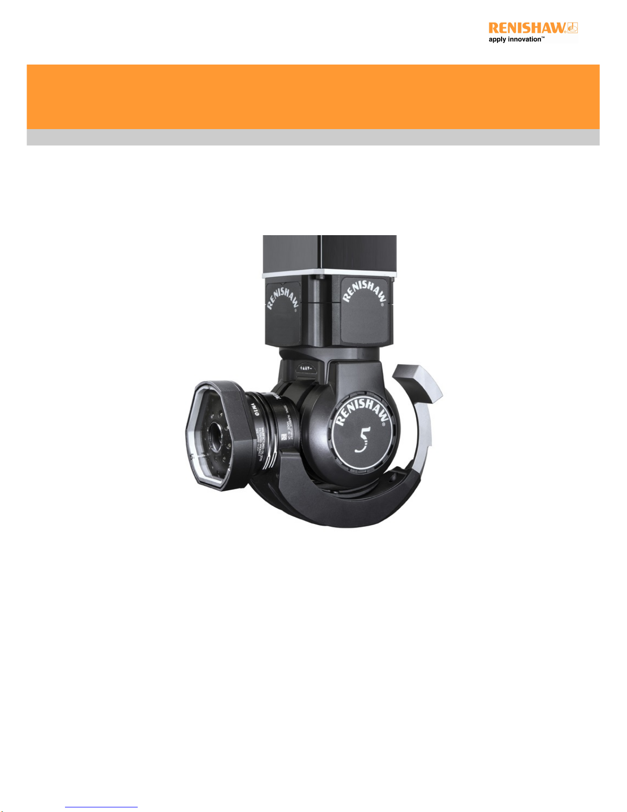
RVP user's guide
Part number: H-1000-3322-01-C
RVP user's guide
www.renishaw.com
Issued 03 2019
1
Page 2
General information
© 2015 ‐ 2019 Renishaw plc. All rights reserved.
This document may not be copied or reproduced in whole or in part, or transferred to any other media or language, by any means, without
the prior written permission of Renishaw.
The publication of material within this document does not imply freedom from the patent rights of Renishaw plc.
Disclaimer
RENISHAW HAS MADE CONSIDERABLE EFFORTS TO ENSURE THE CONTENT OF THIS DOCUMENT IS CORRECT AT THE DATE OF
PUBLICATION BUT MAKES NO WARRANTIES OR REPRESENTATIONS REGARDING THE CONTENT. RENISHAW EXCLUDES LIABILITY,
HOWSOEVER ARISING, FOR ANY INACCURACIES IN THIS DOCUMENT.
Trademarks
RENISHAW® and the probe emblem used in the RENISHAW logo are registered trademarks of Renishaw plc in the UK and other countries.
apply innovation is a trademark of Renishaw plc.
All brand names and product names used in this document are trade names, service marks, trademarks, or registered trademarks of their
respective owners.
Windows XP, Windows 2000, Vista, Windows 7 and Windows 10 are registered trade names of the Microsoft Corporation.
All trademarks and trade names are acknowledged.
WEEE
The use of this symbol on Renishaw products and/or accompanying documentation indicates that the product should not be mixed with the
general household waste upon disposal. It is the responsibility of the end user to dispose of this product at a designated collection point for
waste electrical and electronic equipment (WEEE) to enable reuse or recycling. Correct disposal of this product will help save valuable
resources and prevent potential negative effects on the environment. For more information, please contact your local waste disposal service
or Renishaw distributor.
Warranty
Renishaw plc warrants its equipment for a limited period (as set out in our Standard Terms and Conditions of Sale) provided that it is installed
exactly as defined in associated Renishaw documentation.
Prior consent must be obtained from Renishaw if non-Renishaw equipment (e.g. interfaces and/or cabling) is to be used or substituted. Failure
to comply with this will invalidate the Renishaw warranty.
Claims under warranty must be made from authorised service centres only, which may be advised by the supplier or distributor.
RVP user's guide
www.renishaw.com
Issued 03 2019
2
Page 3
Care of equipment
Renishaw probes and associated systems are precision tools used for obtaining precise measurements and must therefore be treated with
care.
Changes to Renishaw products
Renishaw reserves the right to improve, change or modify its hardware or software without incurring any obligations to make changes to
Renishaw equipment previously sold.
Packaging
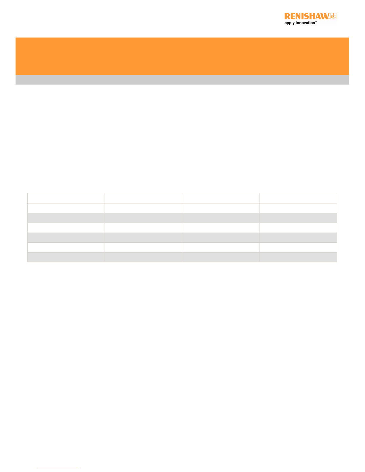
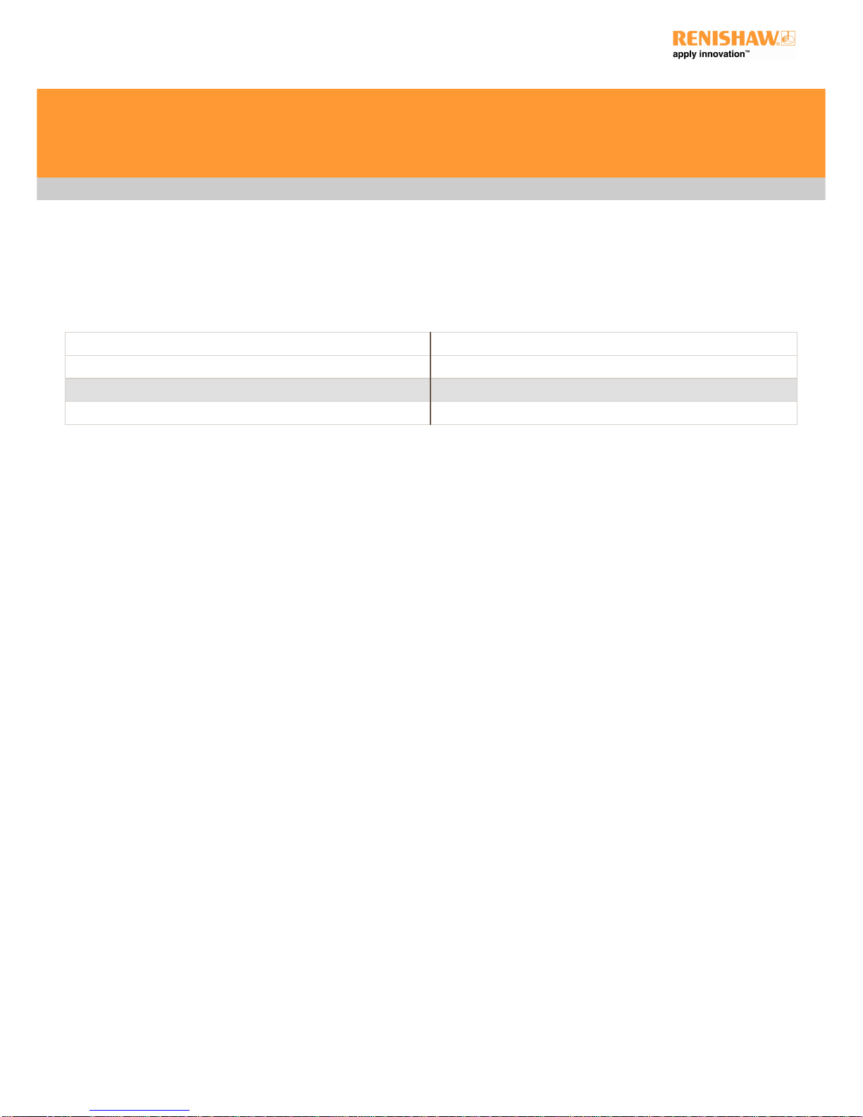
To aid end user recycling and disposal the materials used in the different components of the packaging are stated here:
Packaging component Material 94/62/EC code 94/62/EC number
Outer box Non-corrugated fibreboard PAP 21
Storage box Polypropylene PP 05
Packaging insert Corrugated fibreboard PAP 20
Stylus box Polypropylene PP 05
Stylus box label Polypropylene PP 05
Bag Low density polyethylene LDPE 04
RVP user's guide
www.renishaw.com
Issued 03 2019
3
Page 4
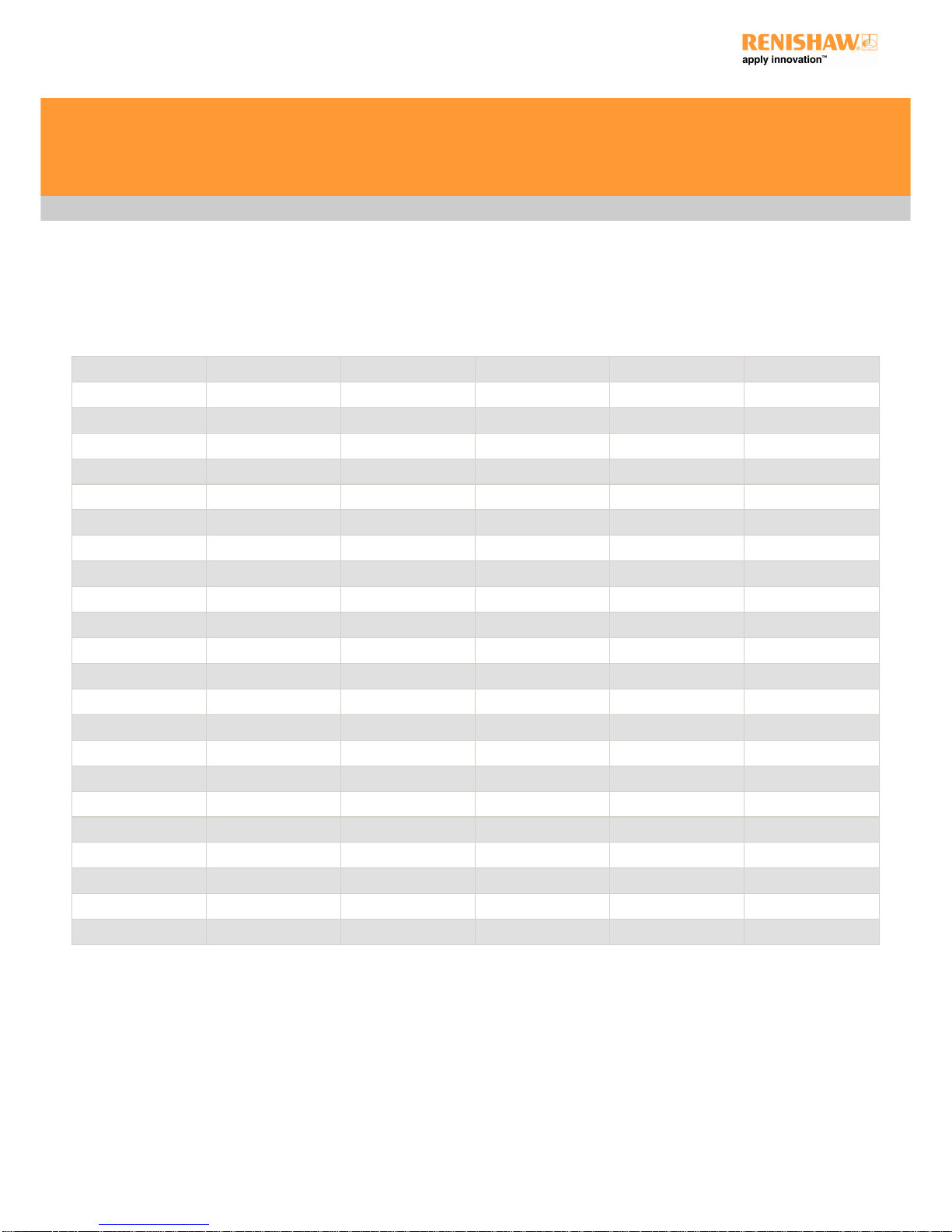
Patents
Features of the RVP system and associated products (such as REVO-2), equipment and techniques are the subjects of one or more of the
following patents and patent applications:
CA2925301 CN100453970 EP1086354 IN2017/009615 JP2016-513248 US2015-0362311
CN101166951 EP1687589 IN259801 JP2016-533484 US2016-0238373
CN101166953 EP1877727 IN279118 JP2018-514773 US2018-0058884
CN101405563 EP1877732 IN292511 JP2018-522240 US2018-0156608
CN101405564 EP1989504 IN294476 JP4695762 US6633051
CN101490430 EP2002206 IN295786 JP5196356 US7533574
CN101772690 EP2002207 IN296310 JP5350216 US7809523
CN102037309 EP2035719 WO2006/114603 JP5425476 US7861430
CN102305613 EP2140318 WO2007/107776 JP5638517 US7885777
CN102906533 EP2167911 WO2009/141606 JP5653581 US7971365
CN103842766 EP2291606 WO2011/135282 JP5658863 US8006398
CN105190230 EP2431707 WO2014/122438 JP5706158 US8186882
CN105408723 EP2564151 WO2014/191729 JP5851969 US8302321
CN105793695 EP2764324 WO2015/049341 JP6013533 US8425119
CN107532930 EP2954283 WO2018/091867 JP6199870 US8474148
CN107850425 EP3004797 JP6348577 US8511898
EP3052926 US8601701
EP3289314 US8756973
EP3322959 US8978261
US9038282
US9366519
US9618329
US9903713
RVP user's guide
www.renishaw.com
Issued 03 2019
4
Page 5

Product compliance
EU declaration of conformity
Contact Renishaw plc or visit www.renishaw.com/EU for the full EU declaration.
FCC (USA only)
Information to user (47 CFR 15.105)
This equipment has been tested and found to comply with the limits for a Class A digital device, pursuant to Part 15 of the FCC rules. These
limits are designed to provide reasonable protection against harmful interference when the equipment is operated in a commercial
environment. This equipment generates, uses, and can radiate radio frequency energy and, if not installed and used in accordance with the
instruction manual, may cause harmful interference to radio communications. Operation of this equipment in a residential area is likely to
cause harmful interference, in which case you will be required to correct the interference at your own expense.
Information to user (47 CFR 15.21)
The user is cautioned that any changes or modifications not expressly approved by Renishaw plc or authorised representative could void the
user's authority to operate the equipment.
Equipment label (47 CFR 15.19)
This device complies with part 15 of the FCC Rules. Operation is subject to the following two conditions:
1. This device may not cause harmful interference.
2. This device must accept any interference received, including interference that may cause undesired operation.
REACH regulation
Information required by Article 33﴾1﴿ of Regulation ﴾EC﴿ No. 1907/2006 ﴾“REACH”﴿ relating to products containing substances of very high
concern (SVHCs) is available at:
www.renishaw.com/REACH
RVP user's guide
www.renishaw.com
Issued 03 2019
5
Page 6
Safety
Before unpacking and installing the RVP system, the user should carefully read the safety instructions below and ensure that they are followed
at all times by all operators.
The RVP vision probe system should only be used with the REVO-2 head.
Operators must be trained in the use and application of the REVO-2 system and accompanying products, in the context of the machine it is
fitted to, before being allowed to operate that machine.
Permanent magnets are used in some components of the REVO-2 system and associated products. It is important to keep them away from
items which may be affected by magnetic fields, e.g. data storage systems, pacemakers and watches.
VM10 and VM11 LED emissions
The VM10 and VM11 vision modules incorporate high power LED lights and should not be used in the event of serious damage to any part of
the VM10 and VM11 modules. In such cases immediately disconnect the power source, remove and do not attempt to reuse the parts. Contact
your supplier for advice.
CAUTION: This equipment uses LED illumination that may flash at a variable rate. Avoid exposure or seek advice from your
medical practitioner if you are susceptible to photosensitivity or related health effects.
RVP user's guide
www.renishaw.com
Issued 03 2019
6
Page 7
Environmental and electrical specifications
Environmental specification
Ambient operating temperature range +10 °C to +40 °C
Storage temperature range ‐25 °C to +70 °C ﴾‐13 °F to 158 °F﴿
Operating humidity 0% to 80% (non-condensing)
Storage humidity 0% to 80% (non-condensing)
Electrical specification
The REVO-2 head and probe electronics are powered from the UCC S5. The head motors are powered from the SPA3. The VPCP and
VMCP are powered by a separate power supply that is supplied by Renishaw. Any additional backlighting is powered by a separate power
supply that is supplied by Renishaw. No additional power supplies are required.
RVP user's guide
www.renishaw.com
Issued 03 2019
7
Page 8

References and associated documents
The following Renishaw documents are referred to in this document or may be a source of further relevant information. They can be
downloaded from www.renishaw.com.
Title Document number
Installation and user's guide: REVO-2 H-1000-7590
Installation guide: UCC S5 H-1000-7598
Installation and user's guide: MCU H-1000-5182
Installation and user's guide: MCU5-2 and MCU W-2 H-1000-5280
RVP user's guide
www.renishaw.com
Issued 03 2019
8
Page 9

System description
RVP is a non-contact vision measurement probe for use with the REVO-2 5-axis measurement system on co-ordinate measuring machines.
RVP increases the multi-sensor capability of REVO-2 by adding non-contact inspection to the existing touch-trigger, high-speed tactile
scanning and surface finish capability of the system.
The RVP system comprises a probe and a range of modules that are automatically interchangeable with all other probe options available for
REVO. This flexibility means that the optimum tool can be selected to inspect a wide range of features, all on one CMM platform.
The RVP system is managed by the same I++ DME compliant interface as REVO-2 and full user functionality is provided by Renishaw's
MODUS metrology software. New MODUS vision software capability includes RVP configuration, image processing with application specific
options and automatic image storage for review and further analysis.
RVP user's guide
www.renishaw.com
Issued 03 2019
9
Page 10

Design principles of the RVP system
The RVP system uses an industry standard CMOS image sensor to capture and then detect the position of features using the contrast between
light and dark areas of the image. Data points are projected on to the location where the image contrast changes from light to dark. A detailed
calibration model of the lens system transforms the co-ordinates of the projected point on the image to real-world, three dimensional coordinates on the part.
RVP user's guide
www.renishaw.com
Issued 03 2019
10
Page 11

System components overview
Key Description Part number
1 REVO-2 head A-5759-0001
2 RVP vision probe A-5378-0080
3 VM10 vision module A-5378-0082
4 VM11 vision module A-5378-0087
5 VPCP probe change port A-5378-0081
6 VMCP module change port A-5378-0083
7 VA10 calibration artefact A-5378-0085
RVP user's guide
www.renishaw.com
Issued 03 2019
11
Page 12

RVP probe
RVP is the probe component of the system that houses the sensor and digital signal processor. There are currently two vision modules that
attach to the probe body that enable the inspection of a range of size and shape features.
The RVP component of the system is automatically interchangeable with other probe options using the VPCP heated change port that can be
fixed to the MRS rack system.
Vision modules
The RVP system features two interchangeable vision modules (VM10 and VM11) which are both tailored to provide inspection capability for
different applications. The vision modules attach to the probe body using the same style kinematic mount utilised by all the current REVO
probes.
VM10 has a wider field of view allowing larger features to be inspected and VM11 has a greater stand-off distance which improves
accessibility when inspecting complex parts with hard to reach features.
VA10 calibration artefact
The VA10 is a dedicated calibration artefact used to calibrate the target feature size and stand-off distance of the RVP system when using a
VM10 or VM11. The calibration routine for RVP is fully automated through MODUS and UCCsuite.
VPCP and VMCP change ports
There are two new change ports that can be mounted to an MRS rack system to allow the automated changing of all the RVP probe and
module components.
The VPCP change port is used to change and house the RVP probe body on the machines rack system. The VMCP change port changes and
houses the vision module components of the RVP system. Both rack ports are temperature controlled to ensure that the housed components
are at the correct and most efficient operating temperature.
RVP user's guide
www.renishaw.com
Issued 03 2019
12
Page 13

Dimensional information
RVP
VM10 and VM11
RVP user's guide
www.renishaw.com
Issued 03 2019
13
Page 14

VPCP and VMCP
VA10
RVP user's guide
www.renishaw.com
Issued 03 2019
14
Page 15

Installation
Fitting VPCP and VMCP to the MRS / MRS2 rack
The VPCP and VMCP heated change ports can be fixed to an MRS or MRS2 rack system. It is recommended that they are attached to the MRS
/ MRS2 rail using the following procedure, where it is assumed that the MRS / MRS2 rack system is correctly installed.
1. Insert one of the fixing screws through the VPCP / VMCP.
2. Position the VPCP / VMCP underneath the rail and locate the respective T-nut within the rail*.
3. Hand tighten the fixing screw into the T-nut and repeat the process for the next fixing screw.
4. Position the VPCP / VMCP and tighten both fixing screws using the hexagonal key supplied.
NOTE: The image above shows the VPCP change port but the procedure is the same for the VMCP change port.
* NOTE: T-nuts must be used with the MRS system. However T-nuts and D-nuts are compatible with the MRS2 system.
RVP user's guide
www.renishaw.com
Issued 03 2019
15
Page 16

Fixing VA10 calibration artefact to CMM
The VA10 calibration artefact is designed to be fixed securely to the bed of the CMM to allow accurate and repeatable calibration of the RVP
system components. The diagrams below show how to fix the VA10 to the bed of the CMM.
1. Locate an appropriate threaded hole in the bed of the machine.
2. Position the artefact plate above the threaded hole.
3. Screw the correct size adaptor stud through the hole into the threaded hole on the machine.
4. Tighten with S spanner supplied.
5. Screw the artefact top component to the adaptor stud.
6. Tighten with S spanner supplied.
RVP user's guide
www.renishaw.com
Issued 03 2019
16
Page 17

Illumination options
RVP lighting techniques
The RVP system has a number of illumination options to ensure that features can be correctly lit allowing accurate and consistent
measurement. Both vision modules have integrated LED illumination to illuminate features that require inspection. The RVP system also uses
a technique which uses back lighting to ensure good contrast of material edges or features.
The lighting technique chosen depends on the type of feature and the material of the part being inspected. RVP system image settings can be
fully customised and adjusted to provide optimum contrast to inspect a range of features.
It is important that the correct exposure is achieved for both front and back lighting applications. The image on the left shows a correctly
exposed back lit hole. The back edge of the hole is sharp and there is good contrast between the material and the white back lit panel.
The image on the right shows a correctly exposed front lit feature. The front edge of the hole is sharp and there is good contrast between the
dark material in the hole and the bright, front lit hole area. When using front lighting, more RVP image settings may need to be adjusted to
get the optimum contrast and to reduce unwanted reflections.
Ambient lighting
Ambient light is an important variable when using the RVP system. For accurate and repeatable inspection, the ambient environment lighting
should be as consistent as possible. Any changes in ambient lighting can potentially affect the system's performance.
RVP user's guide
www.renishaw.com
Issued 03 2019
17
Page 18

Cleaning the RVP system
CAUTION: Always adhere to the safety instructions given on the general safety recommendations and instructions in this
document. Failure to do so could lead to personal injury.
Following the simple procedures given below will prolong the operational life and maintain the high performance of the system. The user
should determine the frequency of inspection and maintenance actions according to the conditions of use.
Kinematic couplings
The kinematic coupling mechanisms incorporated throughout the system have precision ball seating and permanent magnets. It is
recommended that all these features be cleaned before first use, and thereafter at regular intervals.
A cleaning kit for the precision ball seating and permanent magnet is available from your Renishaw supplier (part number A-1085-0016). It
comprises strips of yellow tack material. Use the yellow tack to clean the areas indicated with arrows numbered [1] on the image below.
With clean hands, tear off a small piece, shape into a small ball and press into / onto each of the features in turn, rotating to a fresh piece of
material as you work around.
CAUTION: Ensure no yellow tack debris is left on the surface. The yellow tack should not be used for the electrical contacts [2] or
the optical windows [3].
Electrical contacts
The electrical contacts, indicated with arrows numbered [2] in the image below, should be carefully cleaned with an alcohol-based cleaner (e.g.
IPA) and a lint-free bud. The frequency of cleaning depends on the local environmental conditions, but should be at least every five hundred
changes.
RVP user's guide
www.renishaw.com
Issued 03 2019
18
Page 19

Optical windows
The RVP probe and module optical windows should be cleaned using a proprietary lens cleaning kit to blow or brush debris away from the
window. If debris is still visible, then the optical window should be carefully wiped with a lint free bud and high-purity isopropyl alcohol (IPA).
Extreme care must be taken to avoid damaging the optical coating or scratching the glass. Latex gloves should be worn during the cleaning
procedure and no attempt to directly touch the optical windows should be made.
NOTE: Cleanliness of the optical windows is important to maintain the highest level of performance of the probe and modules. If
any contamination cannot be removed and is resulting in degraded metrology performance, please contact your local Renishaw
office.
RVP user's guide
www.renishaw.com
Issued 03 2019
19
Page 20

Technical terminology
Stand-off
This is the distance between the end of the vision module and the plane at which a feature will be at the sharpest focal distance to provide
optimum image capture.
RVP user's guide
www.renishaw.com
Issued 03 2019
20
Page 21

Field of view
This is the maximum size area that will be projected onto the CMOS sensor when the correct stand-off distance is used. Any feature requiring
inspection with RVP must be located within the field of view to allow inspection.
RVP user's guide
www.renishaw.com
Issued 03 2019
21
Page 22

Depth of field
The depth of field specifies the range over which a feature can deviate from the nominal stand-off distance and still be measured with
acceptable levels of metrology performance. If features are measured outside the recommended depth of field range, metrology performance
and accuracy will decrease.
RVP user's guide
www.renishaw.com
Issued 03 2019
22
Page 23

For worldwide contact details,
please visit our main website at
www.renishaw.com/contact
Renishaw plc
New Mills, Wotton-under-Edge,
Gloucestershire, GL12 8JR
United Kingdom
T +44 (0)1453 524524
F +44 (0)1453 524901
www.renishaw.com/cmmsupport
Issued 03 2019
 Loading...