

Page 1
RSLM high accuracy linear encoder
Installation guide
M-6183-9040-02-A
EVOLUTE™ RTLA50/FASTRACK ™ absolute linear encoder system
Page 2

Contents
Product compliance 1
Storage and handling 2
Installation drawing: EVOLUTE readhead 3
Installation drawing: EVOLUTE readhead (side cable outlet) 4
Installation drawing: RTLA50/FASTRACK (with adhesive datum clamp) 5
RTLA50/FASTRACK installation 6
RTLA50/FASTRACK: Scale datum 7
Readhead mounting/installation 8
Electrical connections 8
Scale technical specifications 8
General specifications 9
Output signals 9
EVOLUTE RTLA50/FASTRACK installation guide
Page 3

Product compliance
C
Renishaw plc declares that EVOLUTE complies with the applicable standards and regulations.
A copy of the EC Declaration of Conformity is available on request.
FCC compliance
This device complies with part 15 of the FCC Rules. Operation is subject to the following two conditions:
(1) This device may not cause harmful interference, and (2) this device must accept any interference
received, including interference that may cause undesired operation.
The user is cautioned that any changes or modifications not expressly approved by Renishaw plc or
authorised representative could void the user’s authority to operate the equipment.
This equipment has been tested and found to comply with the limits for a Class A digital device, pursuant
to part 15 of the FCC Rules. These limits are designed to provide reasonable protection against harmful
interference when the equipment is operated in a commercial environment. This equipment generates,
uses, and can radiate radio frequency energy and, if not installed and used in accordance with the
instruction manual, may cause harmful interference to radio communications. Operation of this equipment
in a residential area is likely to cause harmful interference in which case the user will be required to correct
the interference at his own expense.
NOTE: This unit was tested with shielded cables on the peripheral devices. Shielded cables must be used
with the unit to ensure compliance.
RoHS compliance
Compliant with EC directive 2011/65/EU (RoHS).
Patents
Features of Renishaw’s encoder systems and similar products are the subjects of the following patents and
patent applications:
Disclaimer
RENISHAW HAS MADE CONSIDERABLE EFFORTS TO ENSURE THE CONTENT OF THIS DOCUMENT
IS CORRECT AT THE DATE OF PUBLICATION BUT MAKES NO WARRANTIES OR REPRESENTATIONS
REGARDING THE CONTENT. RENISHAW EXCLUDES LIABILITY, HOWSOEVER ARISING, FOR ANY
INACCURACIES IN THIS DOCUMENT.
The use of this symbol on Renishaw products and/or accompanying documentation indicates that the
product should not be mixed with general household waste upon disposal. It is the responsibility of the end
user to dispose of this product at a designated collection point for waste electrical and electronic equipment
(WEEE) to enable reuse or recycling. Correct disposal of this product will help to save valuable resources
and prevent potential negative effects on the environment. For more information, please contact your local
waste disposal service or Renishaw distributor.
The packaging of our products contains the following materials and can be recycled.
Packaging Component Material ISO 11469 Recycling Guidance
Outer box Cardboard Not applicable Recyclable
Polypropylene PP Recyclable
Inserts Low Density Polyethylene Foam LDPE Recyclable
Cardboard Not applicable Recyclable
Bags High Density Polyethylene Bag HDPE Recyclable
Metalised Polyethylene PE Recyclable
EVOLUTE RTLA50/FASTRACK installation guide
1
CN1260551 US7499827 JP4008356 GB2395005 CN1314511
EP1469969 JP5002559 CN102197282 EP2350570 JP2012507028
US20110173832 KR20110088506 CN102388295 EP2417423 KR20120014902
US2012007980 CN102460077 EP2438402 US20120072169 KR20120026579
US8141265 EP2294363 CN102057256 JP2011524534 KR20110033204
Further information
Further information relating to the EVOLUTE encoder range can be found in the EVOLUTE Data sheets
available from your local representative. This document may not be copied or reproduced in whole or in
part, or transferred to any other media or language, by any means without the written prior permission of
Renishaw. The publication of material within this document does not imply freedom from the patent rights
of Renishaw plc.
Page 4
EVOLUTE RTLA50/FASTRACK installation guide
2
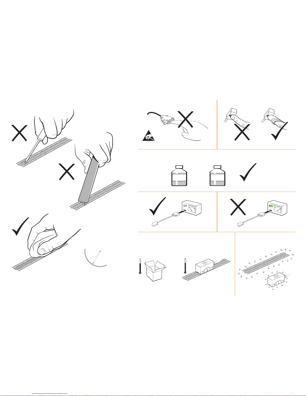
Storage and handling
Storage
Operating
Humidity
RTLA50 – 50 mm
FASTRACK – 200 mm
NOTE: Ensure self-adhesive tape
is on outside of bend radius.
Minimum bend radius
N-heptane
CH3(CH2)5CH
3
Propan-2-ol
CH3CHOHCH
3
Scale and readhead
95% relative humidity
(non-condensing) to
EN 60068-2-78
Readhead
Readhead
Standard
+80 °C
0 °C
System
Standard
+80 °C
−20°C
Page 5

EVOLUTE RTLA50/FASTRACK installation guide
3
Installation drawing: EVOLUTE readhead
Dimensions and tolerances in mm
(Yaw tol. ±0.75°)
Set-up LED
6.5 min
36
18
12
14
2 mounting holes M3 through,
counterbored each side, 3 deep
†
0.31
R>20 Dynamic bend radius
R>10 Static bend radius
(Pitch tol. ±0.5°)
Ø 4.7 ±0.2
3
Optical centreline
17.2
Scale and optical centreline
16.5
(Roll tol. ±0.5°)
0.05
Rideheight 0.6 ±0.25 from
FASTRACK top surface
0.4 FASTRACK
thickness
0.47
7.8
6 typ*
6.4
18
Note: Reversing head orientation
has no effect on count direction.
Orientation of scale
determines count direction
0.75 ±1
A
Detail A
*Extent of mounting faces.
†
Recommended thread engagement 5 mm (8 mm including counterbore). Recommended tightening torque 0.5 to 0.7 Nm.
10 typ*
Moving head
increases count
direction
Moving head
increases count
direction
Page 6

EVOLUTE RTLA50/FASTRACK installation guide
4
Installation drawing: EVOLUTE readhead (side cable outlet)
Dimensions and tolerances in mm
(Yaw tol. ±0.75°)
Set-up LED
6.5 min
36
18
5.9
7.5
12
14
2 mounting holes M3 x 9 deep
counterbored 3 deep
=
0.31
R>20 Dynamic bend radius
R>10 Static bend radius
(Pitch tol. ±0.5°)
Ø 4.7 ±0.2
3
Optical centreline
17.2
Scale and optical centreline
16.5
(Roll tol. ±0.5°)
0.05
Rideheight 0.6 ±0.25 from
FASTRACK top surface
0.47
6 typ*
3
18
NOTE: Reversing head orientation
has no effect on count direction.
0.75 ±1
A
Detail A
* Extent of mounting faces.
†
Recommended thread engagement 5 mm (8 mm including counterbore). Recommended tightening torque 0.5 to 0.7 Nm.
10 typ*
Orientation of scale
determines count direction
0.4 FASTRACK
thickness
Moving head
increases count
direction
Moving head
increases count
direction
Page 7

EVOLUTE RTLA50/FASTRACK installation guide
5
Installation drawing: RTLA50/FASTRACK (with adhesive datum clamp) *
Dimensions and tolerances in mm
RTLA scale (A-9764-xxxx)
FASTRACK
(A-9704-xxxx)
Optional end cover
(Pair A-9589-0058)
18
B
A
Optical centreline
Do not cut FASTRACK
over shaded area
Spot of Loctite® 435™ (2 positions)
to secure axis datum position*
0.75 ±1
Ra 3.2
18 ±0.1
35 max
‡
Overall length (L + 12)
Scale length (L)
Measuring length ML = (L-10)
10 max (gap)
‡
1 min (gap)
§
Detail A
0.1/100
0.5
F
F = axis of motion
FASTRACK length (L - 24)
†
Detail B
F = axis of motion
0.05
F
NOTE: Minimum recommended FASTRACK length = 100 mm. All dimensions applicable when using EVOLUTE side cable outlet version.
* For alternative mechanical datum clamp method see page 7.
†
Assumes 1 mm gap between scale and end covers and zero gap between FASTRACK and end covers. ‡ Only required for sectional installations. § For thermal expansion.
EVOLUTE readhead
Page 8

EVOLUTE RTLA50/FASTRACK installation guide
6
RTLA50/FASTRACK installation
During handling or installation of FASTRACK suitable gloves should be worn to protect against injury from sharp edges.
2
Thoroughly clean and degrease the
substrate and allow to dry.
For FASTRACK location a ledge,
separate straight edge(s) or dowels
can be used.
Check alignment of ledge/separate
straight edge(s) with respect to axis
of motion (see installation drawing).
1
If required cut FASTRACK and scale to length
(separately) using guillotine (A-9589-0071) after
referring to installation drawing.
Guillotine should be held securely in place, using
a suitable vice or clamping method.
Feed FASTRACK or scale through the guillotine
as shown, and place guillotine press block down
onto the FASTRACK/scale.
Ensure the block is in the correct orientation (as
shown). Whilst holding the block in place, in a
smooth motion, pull down the lever to cut through
the FASTRACK/scale.
Before sticking FASTRACK to the
substrate bend the centre section
upwards slightly using a small pair
of pliers.
3
4
Remove backing liner and stick to substrate, locating
against ledge/separate straight edge(s) or dowels.
Ensure complete adhesion to the substrate by
applying firm finger pressure along the length
of the FASTRACK from the centre outwards
towards each end using a lint-free cloth if
required.
NOTE: Allow the FASTRACK a
minimum of 20 minutes to adhere
before removing the centre section.
IMPORTANT: Wear suitable
protective gloves whilst
carrying out this procedure
to avoid risk of cuts.
5
Engage centre section removal tool and with consistent
forward pressure remove centre section.
If the ledge method or similar is used then the
appropriate side panel on the removal tool
(A-9589-0122) will need to be removed
as shown.
Ledge
Side panels
DO NOT CUT
FASTRACK
in these
areas
Guillotine
press block
Page 9

EVOLUTE RTLA50/FASTRACK installation guide
7
RTLA50/FASTRACK installation (Continued)
6
7
8
RTLA50/FASTRACK: Scale datum
The datum clamp fixes the RTLA50 scale rigidly to the substrate at the location chosen.
The metrology of the system may be compromised if the datum clamp is not used.
It can be positioned anywhere along the axis depending upon the customer’s requirements.
There are two scale datum clamp options to choose from, shown below.
Option 1: Mechanical
Option 2: Adhesive
Using dispensing tip P-TL50-0209 apply Loctite 435
between scale and FASTRACK so it wicks underneath
adjacent to user selected datum location as shown.
NOTE: Drawing shows the scale datum adjacent to
the chosen reference mark.
Slide RTLA50 scale into the FASTRACK ensuring the
scale is fed under the projections as shown.
Scale can be installed manually by either
pulling or pushing it through the
FASTRACK carrier.
Alternatively use the optional scale
installation tool (A-9589-0420)
as shown, for easy installation.
Ensure a gap >1 mm
Projections
NOTE: For instructions on how to use
the scale installation tool, download
‘User guide – RTL scale installation
tool (A-9589-0420)’ from the website at:
www.renishaw.com/encoderinstallationguides
IMPORTANT: If manually installing
the scale using fingers, suitable
gloves should be worn to protect
against injury from sharp edges.
Optional: fix self-adhesive end covers
ensuring a gap of at least 1 mm.
Clean FASTRACK and scale using a lint-free cloth.
3
Do not place clamp
tip over shaded area
12
25
RTLA50 clamp
(A-9589-0077)
M3 x 6 low head screw,
supplied with clamp
†
†
Additional screws available (pack of 25 A-9584-2047).
NOTE: Only apply Loctite 435 in
these gaps to ensure best bond.
Loctite 435 will wick under the
scale to lock it to the substrate.
16
12
2.3
1.7
5 min
thread
depth
Page 10

EVOLUTE RTLA50/FASTRACK installation guide
8
Customer
electronics
Extension
cable*
Shield
Serial
communication
signals
0 V
5 V
Readhead
Electrical connections
EVOLUTE grounding and shielding
Connector
Scale technical specifications
RTLA50
Form
0.2 mm x 8 mm (H x W)
Datum fixing
Loctite 435
Material
Hardened and tempered martensitic stainless steel
Accuracy (at 20 °C) ±10 µm/m, calibration traceable to International Standards
Coefficient of thermal expansion (at 20 °C) 10.1 ±0.2 µm/m/°C
Maximum length
10.02 m
FASTRACK
Form
0.4 mm x 18 mm (H x W) (includes adhesive)
Mounting
Self-adhesive backing tape
Material
Hardened and tempered martensitic stainless steel
Coefficient of thermal expansion (at 20 °C) 10.1 ±0.2 µm/m/°C
Minimum recommended length
100 mm
Readhead mounting/installation
Mounting brackets
The bracket must have a flat mounting surface, enable conformance to the installation tolerances, allow
adjustment of the rideheight of the readhead, and be sufficiently stiff to prevent deflection of the readhead
during operation.
Readhead set-up
Ensure that the scale, readhead optical window and mounting face are clean and free from obstructions.
To set nominal rideheight for RTLA50/FASTRACK installations, use the red 0.6 mm readhead spacer on
FASTRACK surface to set rideheight. Adjust the readhead to maximize the signal strength along the full
axis of travel to achieve a Green LED.
Readhead set-up LED status
Green Orange Red
NOTE: A position error will trigger the
set-up LED to flash continuously until
the error is no longer present AND:
1. Power has been cycled OR
2. A position request has been
received from the controller.
Ya w
0° ±0.75°
Pitch
0° ±0.5°
Roll
0° ±0.5°
Rideheight
0.6 ±0.25 mm
(from FASTRACK face)
IMPORTANT: Only use
0.6 mm red spacer.
IMPORTANT: The shield should be connected to the machine earth (Field ground).
IMPORTANT: If the connector is modified or replaced, the customer must ensure both 0 V cores
(White and Green) are connected to 0 V.
*For maximum extension cable length please consult your local Renishaw representative.
Page 11

Function Signal * Wire colour
Pin
9 way D-type
Power
5 V Brown 4, 5
0 V
White
8, 9
Green
Serial
communications
MA+ Violet 2
MA
−
Yellow 3
SLO+ Grey 6
SLO
−
Pink 7
Shield
Shield Shield Case
Function Signal Wire colour
Pin
9 way D-type
Power
5 V Brown 4, 5
0 V
White
8, 9
Green
Serial
communications
MR Violet 2
MRR Yellow 3
Shield
Shield Shield Case
Reserved
Do not connect
Grey 6
Pink 7
EVOLUTE RTLA50/FASTRACK installation guide
9
BiSS C-mode serial comms – output signals
* For details, refer to BiSS
Data sheet L-9709-9005.
General specifications
Power supply 5 V ±10% 1.25 W maximum (250 mA @ 5V)
NOTE: Current consumption figures refer to terminated
EVOLUTE systems. Renishaw encoder systems must be
powered from a 5 V dc supply complying with the requirements
for SELV of standard IEC BS EN 60950-1
Ripple 200 mVpp maximum @ frequency up to 500 kHz
Sealing IP64
Acceleration (readhead)
Operating 500 m/s2, 3 axes
Shock (readhead)
Non-
operating
1000 m/s2, 6 ms, ½ sine, 3 axes
Maximum acceleration
of scale with respect to
readhead
2000 m/s
2
NOTE: This is the worst case figure that is correct for the
slowest communications clock rates. For faster clock rates, the
maximum acceleration of scale with respect to the readhead
can be higher. For more details, please contact your local
representative.
Vibration Operating 300 m/s2, 55 Hz to 2000 Hz, 3 axes
Mass Readhead 18 g
Cable 32 g/m
Readhead cable 7 core, tinned and annealed copper, 28 AWG
Single-shielded, outside diameter 4.7 ±0.2 mm
Flex life >40 x 106 cycles at 20 mm bend radius
UL recognised component
Maximum cable length
3 m
For maximum extension cable length, contact your local
Renishaw representative.
Mitsubishi serial comms – output signals
9 way D-type plug
31
16
52
Output signals
The EVOLUTE encoder system has been designed to the relevant EMC standards, but must
be correctly integrated to achieve EMC compliance. In particular, attention to shielding
arrangements is essential.
Function Signal Wire colour
Pin
9 way D-type
Power
5 V Brown 4, 5
0 V
White
8, 9
Green
Serial
communications
S Violet 2
S Yellow 3
Shield
Shield Shield Case
Reserved
Do not connect
Grey 6
Pink 7
Yaskawa serial comms – output signals
Page 12

Renishaw plc
New Mills, Wotton-under-Edge,
Gloucestershire GL12 8JR
United Kingdom
T +44 (0)1453 524524
F +44 (0)1453 524901
E uk@renishaw.com
www.renishaw.com
For worldwide contact details,
please visit our main website at
www.renishaw.com/contact
RENISHAW and the probe symbol used in the RENISHAW logo are registered trade marks of
Renishaw plc in the United Kingdom and other countries.
apply innovation and names and designations of other Renishaw products and technologies
are trade marks of Renishaw plc or its subsidiaries.
© 2016–2018 Renishaw plc All rights reserved Issued 0218
BiSS ® is a registered trademark of iC-Haus GmbH.
Loctite ® is a registered trademark of the Henkel Corporation.
RSLM high accuracy linear encoder
*M-6183-9040-02*
 Loading...