

Page 1
Installation guide
M-9414-9446-01-A
ATOM DX
RSLM high accuracy linear encoder
™
linear encoder systems
Page 2

Contents
Product compliance 1
Storage and handling 2
ATOM DX system installation overview 3
RTLF tape scale:
Installation drawing 4
Application methods 5
Mounting (for lengths <500 mm only) 6
Application (any length) 7
Datum clamp 8
End covers 8
Reference mark deselection 8
RCLC glass spar scale:
Installation drawing 9
ATOM DX calibration overview 16
System calibration 17
Restoring factory defaults 17
Enabling/disabling AGC 17
Readhead LED diagnostics 17
Troubleshooting 18
ATOM DX
Cabled readhead dimensions 20
Top exit readhead dimensions 21
Readhead brackets dimensions 22
Output signals 23
Speed 24
Mounting 10
System connection: Top exit readhead 11
Readhead mounting and alignment:
Methods 12
Shim kit (A-9401-0050) 13
Dummy head (A-9401-0072) 14
Accurate bracket and feeler gauge 15
ATOM DX linear installation guide
Electrical connections 25
Output specications 26
General specications 27
Scale specications 27
RTLF tape scale 27
RCLC glass spar scale 27
Page 3
Product compliance
C
Renishaw plc declares that ATOM DX complies with the applicable standards and regulations.
A copy of the EU Declaration of Conformity is available from our website at
www.renishaw.com/productcompliance
FCC compliance
This device complies with part 15 of the FCC Rules. Operation is subject to the following two conditions:
(1) This device may not cause harmful interference, and (2) this device must accept any interference
received, including interference that may cause undesired operation.
The user is cautioned that any changes or modications not expressly approved by Renishaw plc
or authorised representative could void the user’s authority to operate the equipment.
This equipment has been tested and found to comply with the limits for a Class A digital device,
pursuant to part 15 of the FCC Rules. These limits are designed to provide reasonable protection
against harmful interference when the equipment is operated in a commercial environment.
This equipment generates, uses, and can radiate radio frequency energy and, if not installed
and used in accordance with the instruction manual, may cause harmful interference to radio
communications. Operation of this equipment in a residential area is likely to cause harmful
interference in which case the user will be required to correct the interference at his own expense.
NOTE: This unit was tested with shielded cables on the peripheral devices. Shielded cables must
be used with the unit to ensure compliance.
ATOM DX top exit readhead
The ATOM DX top exit readhead has been designed as a system component and to be compliant with
EMC regulations for products of its type. Care must be taken with shielding and grounding arrangements
to ensure EMC performance once installed. It is the system integrator’s responsibility to implement, test
and prove EMC compatibility for the whole machine
Further information
Further information relating to the ATOM DX encoder range can be found in the ATOM DX system Data
sheet (L-9517-9736), Advanced Diagnostic Tool ADTi -100 Data sheet (L-9517-9699), Advanced Diagnostic
Tool ADTi -100 and ADT View software quick-start guide (M-6195-9321), and the Advanced Diagnostic Tool
ADTi -100 and ADT View software user guide (M-6195-9413). These can be downloaded from our website at
www.renishaw.com /opticalencoders and are also available from your local representative. This document
may not be copied or reproduced in whole or in part, or transferred to any other media or language, by any
means without the written prior permission of Renishaw. The publication of material within this document does
not imply freedom from the patent rights of Renishaw plc.
Disclaimer
RENISHAW HAS MADE CONSIDERABLE EFFORTS TO ENSURE THE CONTENT OF THIS DOCUMENT
IS CORRECT AT THE DATE OF PUBLICATION BUT MAKES NO WARRANTIES OR REPRESENTATIONS
REGARDING THE CONTENT. RENISHAW EXCLUDES LIABILITY, HOWSOEVER ARISING, FOR ANY
INACCURACIES IN THIS DOCUMENT.
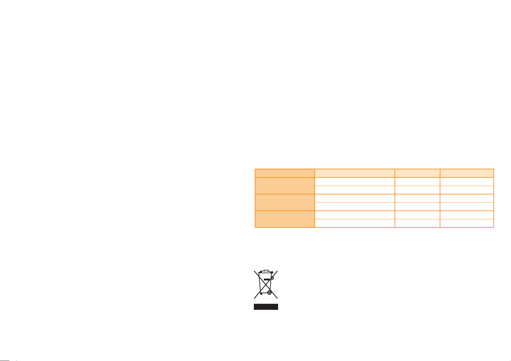
The packaging of our products contains the following materials and can be recycled.
Packaging Component Material ISO 11469 Recycling Guidance
Outer box
Inserts
Bags
Low Density Polyethylene Foam LDPE Recyclable
High Density Polyethylene Bag HDPE Recyclable
Cardboard Not applicable Recyclable
Polypropylene PP Recyclable
Cardboard Not applicable Recyclable
Metalised Polyethylene PE Recyclable
Patents
Features of Renishaw’s encoder systems and similar products are the subjects of the following
patents and patent applications:
CN1314511 EP1469969 EP2390045 JP5002559
US8987633 US8466943 CN101300463 EP1946048
JP5017275 US7624513 CN101310165 EP1957943
US7839296 CN105008865 US9952068 CN109477736
EP3465099 US2017203210
ATOM DX linear installation guide
REACH regulation
Information required by Article 33(1) of Regulation (EC) No. 1907/2006 (“REACH”) relating to products
containing substances of very high concern (SVHCs) is available at: www.renishaw.com / REACH
The use of this symbol on Renishaw products and/or accompanying documentation indicates that
the product should not be mixed with general household waste upon disposal. It is the responsibility
of the end user to dispose of this product at a designated collection point for waste electrical and
electronic equipment (WEEE) to enable reuse or recycling. Correct disposal of this product will help
to save valuable resources and prevent potential negative effects on the environment.
For more information, please contact your local waste disposal service or Renishaw distributor.
1
Page 4
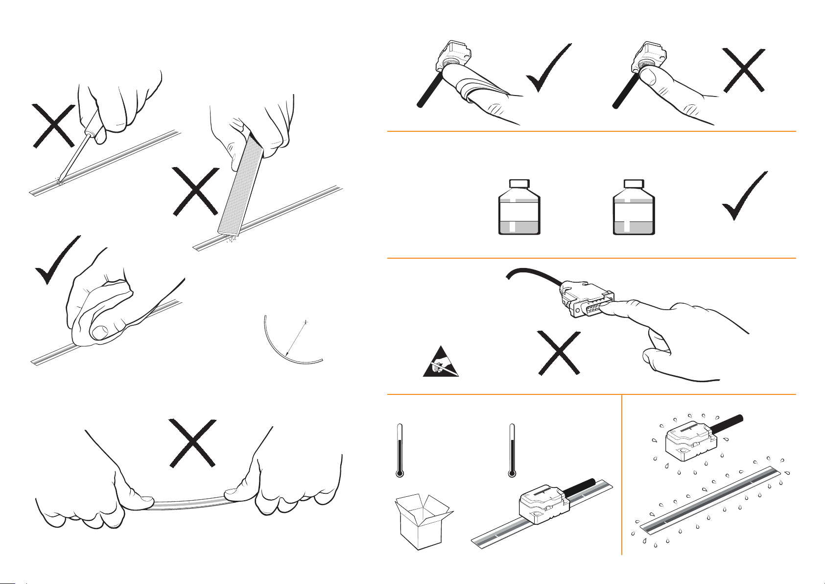
Storage and handling
RTLF and RCLC scales
Scale and readhead
RCLC scale only
Minimum bend radius
RTLF – 150 mm
NOTE: Ensure self-adhesive tape
is on the outside of bend.
Storage
+70 °C
−20 °C
N-heptane
CH
(CH2)5CH
3
3
Operating
+70 °C
0 °C
Propan-2-ol
CH3CHOHCH
3
Humidity
ATOM DX linear installation guide
95% relative humidity
(non-condensing)
to EN 60068-2-78
2
Page 5
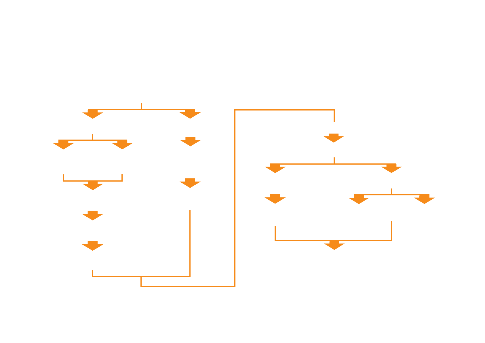
ATOM DX system installation overview
This section gives an overview of the steps involved in installing, setting-up and calibrating an ATOM DX encoder system.
More detailed information is contained within the rest of the document.
For information on designing the readhead and scale into the system refer to the detailed installation drawings
and 3D models at www.renishaw.com /opticalencoders or contact your local Renishaw representative.
For information on the ATOM DX product range refer to the ATOM DX data sheet L-9517-9736.
IMPORTANT: Prior to installing readhead and scale, installation drawings should be reviewed to ensure correct orientation of readhead relative to scale.
Scale mounting
RTLF (tape scale)
Ledge or dowel mount
<500 mm only
(see page 6).
Fit datum clamp
(see page 8).
Fit end covers
(see page 8).
Deselect unused reference marks
(see page 8).
Scale applicator
Any length
(see page 7).
RCLC (glass spar)
Ledge or
dowel mount
(see page 10).
Fit datum clamp
(see page 10).
Fixed mounting
Shim kit
(see page 13).
System connection
Mount and align readhead
Dummy head
(see page 14).
Calibrate system
(see page 17).
Adjustable bracket
Accurate bracket
(see page 15).
ATOM DX linear installation guide
3
Page 6
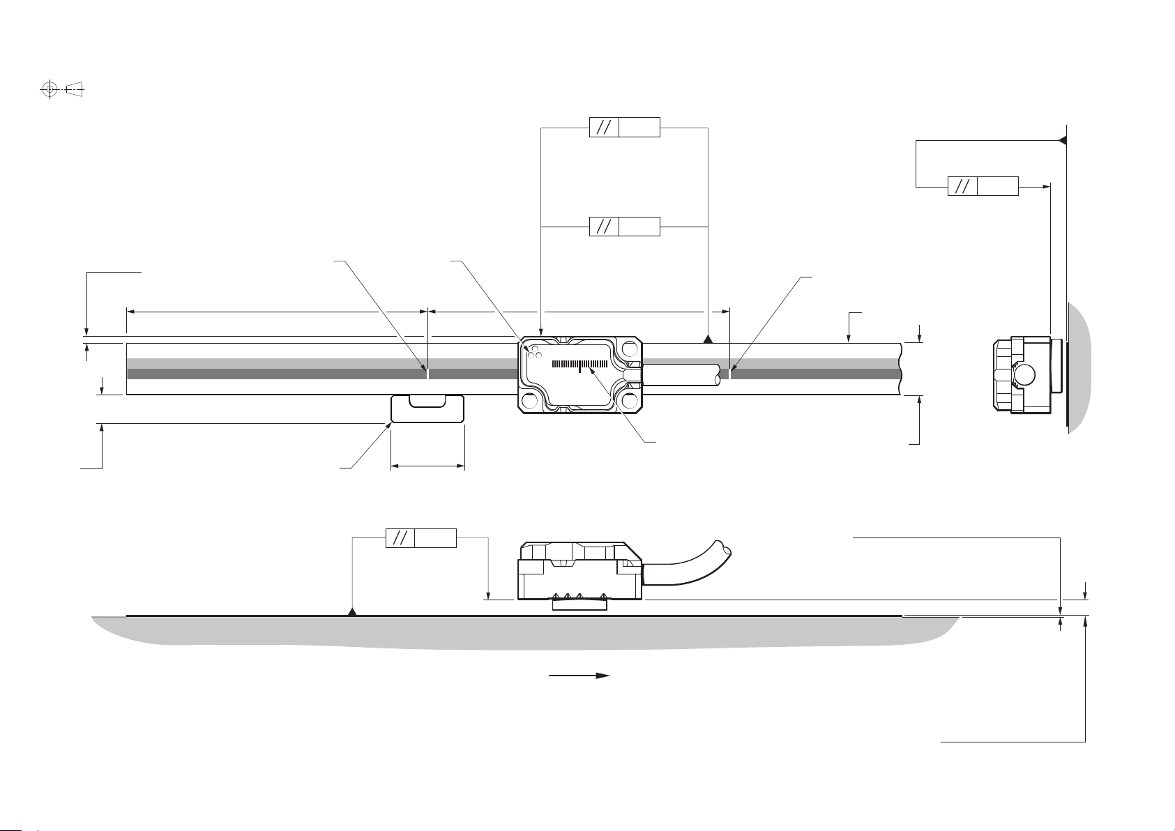
RTLF tape scale: Installation drawing (Cabled readhead shown)
For dimensioned readhead drawings see pages 20 and 21.
40 µm version
(Yaw tol. ±1°)
0.36
20 µm version
(Yaw tol. ±0.5°)
0.18
Dimensions and tolerances in mm
(Roll tol. ±1°)
0.22
1.02 ±0.25
4.5
Measuring length = Overall length − 3 mm
For detailed installation drawings refer to www.renishaw.com /opticalencoders
Reference mark
50
Datum clamp
A-9585-0028)
(see page 8)
Set-up LED
12
(Pitch tol. ±1°)
0.36
50
Forward direction of readhead
relative to scale
Readhead/ scale orientation
Reference mark
Scale datum edge
8
Scale thickness (including adhesive) 0.41
Rideheight (for calibration):
2.5 ±0.08 (40 µm version)
2.5 ±0.04 (20 µm version)
Operating rideheight:
2.5 ±0.11 (40 µm version)
2.5 ±0.055 (20 µm version)
ATOM DX linear installation guide
4
Page 7
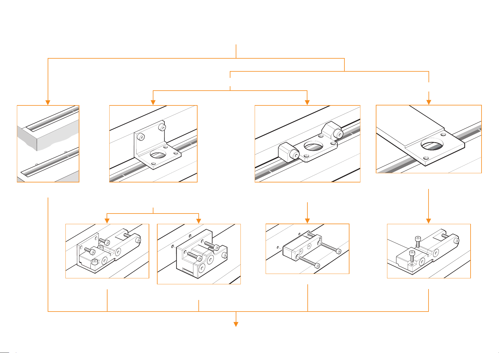
RTLF tape scale: Installation methods
RTLF scale application depends upon scale length and bracket type
RTLF tape scale
Ledge or dowel mounting
(see page 6).
Mounting (<500 mm only)
Datum edge of readhead located against
a ledge on the bracket to control yaw.
For use with ‘ L’ mounting bracket A-9402-0037
or customer designed bracket.
Adjustable bracket
Application (any length)
Datum edge of readhead mounted against machine axis.
For use with side mounting bracket A-9401-0103 or
customer designed bracket.
Fixed mounting
Readhead mounting is integral to the machine and
does not allow rideheight adjustment.
Top mount applicator A-9402-0028
(see page 7).
ATOM DX linear installation guide
Slim applicator A-9402-0060 (see page 7).
Side mounted applicator A-9402-0034. Only for
use with ‘ L’ mounting bracket A-9402-0037
(see page 7).
Install datum clamp, end covers and deselect reference marks (see page 8).
Top mount applicator A-9402-0028
(see page 7).
5
Page 8
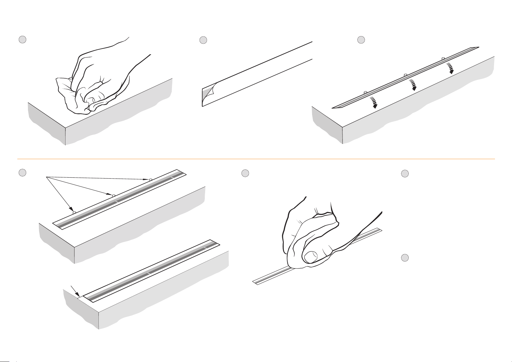
RTLF tape scale: Mounting (for lengths <500 mm only)
1
Thoroughly clean and
degrease the substrate
with a lint-free cloth.
Support
4
dowels
2
Remove backing paper from scale.
Clean scale using Renishaw scale cleaning wipes
5
(A-9523-4040) or a clean, dry, lint-free cloth.
3
Locate scale against dowels or ledge
and rotate down onto substrate.
*
If dowels or ledge are permanent, their maximum
height above substrate is 0.6 mm.
Install datum clamp, end covers and
6
deselect reference marks as
detailed on page 8.
*
Location ledge
ATOM DX linear installation guide
or
Remove temporary dowels (if tted).
7
6
Page 9
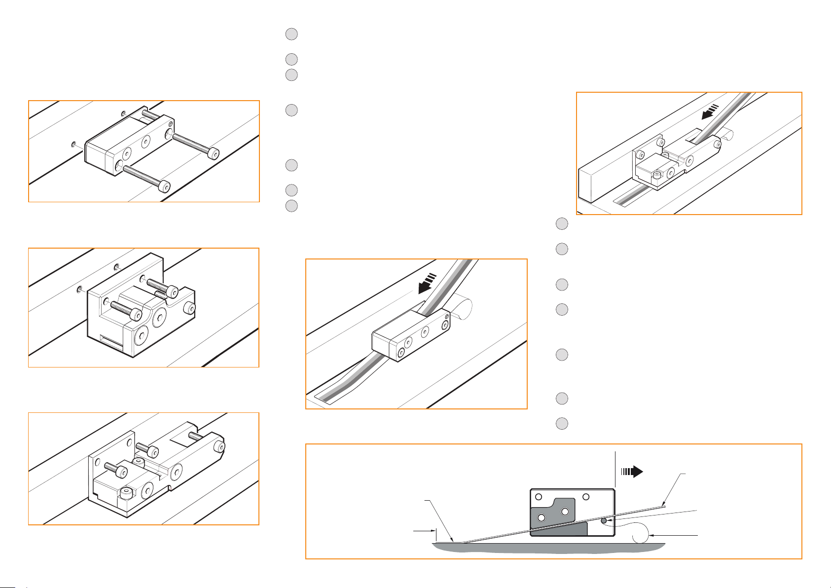
RTLF tape scale: Application (any length)
There are three versions of applicator for use with RTLF scale
depending upon the design of the readhead mounting bracket:
Slim applicator (A-9402-0060) which is mounted in place of the
readhead bracket. It can be used in conjunction with the side
mounting bracket (A-9401-0103) or a customer designed bracket.
Side mount applicator (A-9402-0034) which is mounted in place
of the readhead bracket. It can be used in conjunction with the
‘L’ mounting bracket (A-9402-0037) or a customer designed bracket.
Top mount applicator (A-9402-0028) which is mounted in place
of the readhead. It can be used in conjunction with the
‘L’ mounting bracket (A-9402-0037) or a customer designed bracket.
Allow scale to acclimatize to installation environment prior to
1
installation.
2
Mark out the ‘START’- position for the scale on the axis substrate.
3
Thoroughly clean and degrease the substrate using a lint free cloth
and recommended solvents (see 'Storage and handling'). Allow
substrate to dry before applying scale.
Slim and side mount applicators:
4
Mount the applicator in place of the readhead bracket.
Top mount applicator:
Mount the applicator on a specically designed bracket in place
of the readhead.
Move axis to scale 'START' position, leaving enough room for the
5
scale to be inserted through the applicator, as shown below.
Check correct scale orientation.
6
When using the slim or side mount applicators begin to peel off
7
the backing paper from the end of the scale and insert the scale
into the applicator up to the ‘START’ point. Ensure the backing
paper feeds out of the back of the applicator around the splitter
screw as shown.
When using the top mount applicator cut the backing paper
approximately 30 mm from the end of the scale. Leaving the
end piece adhering to the scale begin to peel off the remaining
backing paper. Insert the scale into the applicator up to the
start position. Ensure the backing paper feeds out of the
back of the applicator round the splitter screw as shown.
Apply nger pressure via a clean lint free cloth to ensure scale
8
end adheres well to the substrate.
Slowly and smoothly move the applicator through the entire
9
length of travel, ensuring the backing paper is pulled manually
from the scale and does not catch under the applicator.
During installation ensure scale is adhered to substrate using
10
light nger pressure.
Remove applicator carefully and, if necessary, adhere the
11
remaining scale manually. NOTE: when using the top mount
applicator ensure the backing paper left at the start of the axis
is removed.
Apply a rm nger pressure via a clean lint-free cloth along the
12
length of the scale after application to ensure complete adhesion.
Slim and side mount applicators:
Fit readhead mounting bracket after removal of scale applicator.
Clean the scale using Renishaw scale wipes (A-9523-4040)
13
or a clean, dry, lint-free cloth.
Fit datum clamp and end covers and, if needed, deselect
14
reference marks that are not required as detailed on page 8.
For more information on designing your bracket and mounting the
chosen scale applicator contact your local Renishaw representative.
ATOM DX linear installation guide
Side mount applicator shown
Scale (attached to
substrate)
START position
Direction of scale application
Scale
‘Splitter screw’
Backing paper
7
Page 10

RTLF: Datum clamp
The datum clamp (A-9585-0028) xes the RTLF scale rigidly to the substrate at the location chosen.
The metrology of the system may be compromised if the datum clamp is not used.
The datum clamp does not need to be tted adjacent to a reference mark. It can be positioned anywhere
along the axis depending upon the customer’s requirements.
Remove the backing paper from the datum clamp.
1
Place the datum clamp with cut-out against the
scale at the chosen location.
Place a small amount of adhesive (Loctite® 435™)
2
in the cut-out on the datum clamp, ensuring none
of the adhesive wicks onto the scale surface.
Dispensing tips P-TL50-0209 are available.
Ensure the adhesive wicks along
A-9585-0028
the entire length of cut-out.
RTLF: End covers
The end cover kit (A-9585-0035) is designed to be used with
RTLF scale to provide protection for exposed scale ends.
NOTE: End covers are optional and can be tted
before or after readhead installation.
Remove the backing paper from
1
the adhesive tape on the back
of the end cover.
8
22
Dimensions in mm
RTLF: Reference mark deselection
RTLF scale >100 mm in length has reference marks every 50 mm. Stickers can be used to deselect all
unused reference marks (A-9402-0049 for a sheet of 20). The stickers are aligned on the backing paper
with a 50 mm spacing so two can be selected at once for deselecting two reference marks.
4
1
Ensure the scale is free from dirt and grease
by cleaning with a scale wipe (A-9523-4040)
or suitable solvent.
2
Place the transparent applicator lm over the
reference mark deselector stickers and rub rmly
until the sticker adheres to the applicator lm.
Two stickers can be selected at once.
3
Remove the applicator lm, complete with
the stickers, from the backing paper.
Incremental track
Align the stickers on the scale over the
reference marks that are not required,
as shown in the diagram, then rub rmly
on the applicator lm until the stickers
adhere to the scale.
Care should be taken to ensure the stickers
fully cover the reference mark and do not
obscure any of the incremental track.
Applicator film
Deselected
reference marks
Align markers on the edges of the end cover with the end
2
of the scale and place end cover over the scale.
NOTE: There will be a gap* between
the end of the scale and the
adhesive tape on the
end cover.
ATOM DX linear installation guide
*
gap
Self adhesive reference mark deselector
stickers on backing paper
5
Remove applicator lm.
8
Page 11

RCLC glass spar scale: Installation drawing (Cabled readhead shown)
For dimensioned readhead drawings see pages 20 and 21.
40 µm version
(Yaw tol. ±1°)
End reference mark
readhead orientation
0.36
Dimensions and tolerances in mm
Mid reference mark
readhead orientation
Readhead datum face
1.42 ±0.25
5
Adhesive datum clamp
(length 8 - 16, width 1 - 5)
(A-9531-0342)
(see page 10)
(Pitch tol. ±1°)
End reference mark
*
0.36
20 µm version
(Yaw tol. ±0.5°)
0.18
Set-up LED
Readhead/scale orientation
Scale datum edge
Mid reference mark
(Roll tol. ±1°)
0.22
L / 2
6.82 ±0.25
A-9404-4018
6.35
Scale thickness (including adhesive) 1.1
Forward direction of readhead
relative to scale
*
Can be applied on one or both sides of the scale.
Overall length L (mm) 10
†
18 30 55 80 100 105 130
Measuring length (mm) 7 15 27 52 77 97 102 127
†
20 µm pitch RCLC scale only.
ATOM DX linear installation guide
Rideheight (for calibration):
2.5 ±0.08 (40 µm version)
Forward direction of readhead
relative to scale
2.5 ±0.04 (20 µm version)
Operating rideheight:
2.5 ±0.11 (40 µm version)
2.5 ±0.055 (20 µm version)
For detailed installation drawings refer to www.renishaw.com /opticalencoders
9
Page 12

RCLC glass spar scale: Mounting
Thoroughly clean and
1
degrease the substrate
with a lint-free cloth.
Support
5
dowels
Remove backing paper from scale.
2
3
Ensure correct orientation of the scale for chosen
reference mark location (middle or end of scale) and
readhead orientation. See ‘RCLC glass spar scale:
Installation drawing’ for details.
Apply llet of adhesive (A-9531-0342). Adhesive can
6
be applied to one or both sides of the scale.
Ensure adhesive does not wick onto scale surface.
(End reference mark shown).
Datum clamp does not need to be positioned adjacent
to a reference mark. It can be positioned anywhere
along the axis depending upon the
customers’ requirements.
Locate scale against dowels or ledge
4
and rotate down onto substrate.
*
If dowels or ledge are permanent, their maximum height
above substrate is 1.2 mm.
After 24 hours when adhesive is cured, clean scale
7
using Renishaw scale wipes (A-9523-4040) or
a clean, dry, lint-free cloth.
*
Location ledge
ATOM DX linear installation guide
or
Remove temporary dowels (if tted).
8
10
Page 13

System connection: Top exit readhead
A range of cables for top exit readheads are available;
15 way D-type connector 10 way JST
Cable length (m) Part number
0.5 A-9414-1223
1.0 A-9414-1225
1.5 A-9414-1226
3.0 A-9414-1228
u
Provide appropriate strain relief at the readhead. The Renishaw top exit cables
are fitted with a P-clip to ensure appropriate cable strain relief.
u
When using Renishaw’s top exit cables ensure that the P-clip is mounted within a
50mm radius of the readhead cable exit.
u
Minimum static bend radius of cores is 3 mm.
u
For challenging dynamic applications consider additional strain relief of the cores.
u
Ensure there is no relative movement between the readhead and the P-clip.
u
The maximum number of insertions for the readhead connector is 20 cycles.
Care should be taken when removing the connector to avoid pulling out cores
from the cable connector.
Cable length (m) Part number
0.5 A-9414-1233
1.0 A-9414-1235
1.5 A-9414-1236
3.0 A-9414-1238
Shielding
For optimum performance:
u
Ensure 100% shielding.
u
Ground the mounting brackets.
u
Ensure continuity between the readhead body and cable shield. For Renishaw
top exit cables the P-clip provides electrical connection to the cable shield.
u
Maximise the distance between the encoder and motor cables.
Top exit readhead (with readhead cable inserted)
A
Detail B: P-clip dimensions
10
4
11.07
B
Detail A: Connector (readhead end) and P-clip
88
6.8
2.5
5.7 ±0.05
P-clip
Use M2 tapping drill
(∅1.6) as clearance
for pin
ATOM DX linear installation guide
∅1.5 ±0.05
2.09
5
2
Hole for M2 screw
11
Page 14

Readhead mounting and alignment: Methods
There is a range of tools available to assist with readhead installation depending upon the system design and
these are detailed below. For more details on designing the mounting bracket and selecting the appropriate
mounting tools contact your local Renishaw representative.
Ensure that the scale, readhead optical window and mounting face are clean and free from obstruction.
Do not saturate the readhead window with cleaning solvent as this may cause contamination on the inside
of the readhead window which cannot be cleaned.
IMPORTANT: Whichever method is used to mount the readhead, care should be taken to ensure the scale surface
is not damaged during this operation, particularly when metal-to-metal contact is necessary.
NOTE: Cabled readhead shown but the same readhead mounting and alignment methods are applicable for
top exit readheads.
Fixed mounting
Readhead mounting
bracket does not
allow for adjustment
of rideheight
Shim kit (see page 13).
Adjustable
bracket
Readhead mounting
bracket allows
adjustment of
rideheight
Dummy head (see page 14).
Accurate bracket and feeler gauge (see page 15).
ATOM DX linear installation guide
12
Page 15

Shim kit (A-9401-0050)
This method is intended for
applications where the
rideheight of the readhead
cannot be adjusted.
Readhead mounting surface
Shims of a known thickness are inserted between the mounting face of the readhead and the bracket to give
the correct rideheight of 2.5 mm (±0.2 mm).
Shims
2.3 ±0.2 mm
Top of
scale
The system should be designed to
achieve a nominal distance of
2.3 mm (±0.2 mm) from the readhead
mounting surface to the top of the scale.
2
Subtract the distance measured from the
nominal rideheight of 2.5 mm to calculate
the required shim thickness.
For example, if the distance measured
is 2.37 mm, the required shim thickness
is 130 µm.
Select a combination of two shims that
3
gets within 10 µm of the difference.
For distances less than 100 µm a single
shim should be used, for distances greater
than 100 µm select one thick (≥100 µm)
and one thin (<100 µm) shim.
In the above example this could either be
1 × 100 µm shim and 1 × 40 µm shim or
1 × 100 µm shim and 1 × 20 µm shim.
The kit consists of:
Part numbers
Shim thickness
(µm)
Quantity in
pack
1
Using a digital dial gauge or similar measure
the distance from the readhead mounting
surface to the scale surface.
Care must be taken to ensure the scale
surface is not scratched.
Renishaw offer a DTi adapter (A-9401-0105)
that can be used to assist with this process.
– Insert the gauge into the adapter and
zero the gauge on a at surface.
– Position or x the gauge/adapter in
place of the readhead and measure
the distance to the scale surface.
Contact your local Renishaw representative
for details of the DTi adapter and digital
dial gauge.
A-9401-
0041
20 40 60 80 100 200 300
10 10 10 10 20 20 10
A-9401-
0042
A-9401-
0043
A-9401-
0044
A-9401-
0045
A-9401-
0046
A-9401-
0047
DTi adapter
Readhead
mounting
surface
4
Place the chosen shim(s) between the
readhead and the bracket.
5
Fix the readhead to the bracket using
2 off M2 × 6 screws in diagonally opposite
xing holes, ensuring that the readhead is
tightened down evenly and parallel to the
bracket face.
6
Connect the readhead to the receiving
electronics and power-up.
7
Check the readhead set-up LED is ashing
Green along the full axis of travel.
8
Proceed with ‘System calibration’ section
(see page 17).
ATOM DX linear installation guide
13
Page 16

Dummy head (A-9401-0072)
The reusable dummy head has the same mounting holes as the ATOM DX readhead
with a longer ‘nose’ that is machined to the optimum rideheight (2.5 mm ±0.02 mm).
It is mounted in place of the readhead directly onto the bracket.
The bracket should have a shoulder to control readhead yaw.
Contact your local Renishaw representative for more information on bracket design.
1
Mount the dummy head onto the bracket using 2 off M2 × 6 screws.
Side mount bracket
A-9401-0103
2
Loosely mount the readhead bracket onto the axis.
Shoulder
‘ L’ mount bracket
A-9402-0037
4
Tighten the bracket xing screws whilst ensuring good contact between the ‘nose’ of the dummy head
and the surface of the scale.
5
Remove the dummy head.
6
Install the ATOM DX readhead in place of the dummy head using M2 × 6 screws in diagonally opposite
xing holes. Ensure the readhead is pushed back against the shoulder of the bracket or mounting face.
3
Adjust the height of the bracket until the ‘nose’ of the dummy head touches the scale.
ATOM DX linear installation guide
7
Connect the readhead to the receiving electronics and power-up.
8
Check the readhead set-up LED is ashing Green along the full axis of travel.
9
Proceed with ‘System calibration’ section (see page 17).
14
Page 17

Accurate bracket and feeler gauge
Fix the readhead directly onto a mounting bracket with a thickness of 2 ±0.02 mm
then use a 0.5 mm feeler gauge to set the rideheight.
NOTE: Bracket A-9401-0103 is not suitable for this installation method.
For more information on system tolerances refer to the installation drawings on
www.renishaw.com /opticalencoders.
For more information on bracket design contact your local Renishaw representative.
1
Mount the readhead onto the bracket using 2 off M2 × 6 screws.
2
Loosely mount the readhead bracket onto the axis.
3
Place the feeler gauge between the readhead bracket and the scale.
Rideheight
Feeler gauge
4
Tighten the bracket xing screws whilst ensuring good contact between bracket, shim and
surface of the scale.
Connect the readhead to the receiving electronics and power-up.
5
Check the readhead set-up LED is ashing Green along the full axis of travel.
6
Proceed with ‘System calibration’ section (see page 17).
7
ATOM DX linear installation guide
15
Page 18

ATOM DX calibration overview
This section is a quick-start guide to calibrating an ATOM DX encoder system.
More detailed information on calibrating the readhead is on page 17 of this installation guide.
The optional Advanced Diagnostic Tool ADTi-100* (A-6165-0100) and ADT View software† can be used to aid installation and calibration.
Calibrate system
Ensure the readhead set-up LED is ashing Green along the full axis of travel before system calibration.
See pages 12 to 15 for more information on readhead mounting and alignment.
Cycle the power to the readhead to initiate the calibration routine. The LED will single ash Blue.
Move the readhead along the scale at slow speed (<100 mm/s), without passing a reference mark, until the LED starts double ashing Blue.
No reference mark
If a reference mark is not being used, the calibration
routine should now be exited by cycling the power.
The LED will stop ashing.
The system is now calibrated and ready for use. Calibration values, Automatic Gain Control (AGC) and
Automatic Offset Control (AOC) status are stored in readhead non-volatile memory at power down.
NOTE: If calibration fails (LED remains single ashing Blue), restore factory defaults by obscuring the
readhead optical window on power-up (see page 17) then repeat the installation and calibration routine.
*
For more details refer to the ‘Advanced Diagnostic Tool ADTi-100 and ADT View software quick start guide’ (M-6195-9321) and ‘Advanced Diagnostic Tool ADTi-100 and ADT View software user guide’ (M-6195-9413).
†
The software can be downloaded for free from www.renishaw.com /adt.
Move the readhead back and forth over the chosen reference
Reference mark
mark until the LED stops ashing.
ATOM DX linear installation guide
16
Page 19

System calibration
NOTE: System calibration (CAL), restoring factory defaults and enabling/disabling AGC functions
can also be carried out using the optional ADTi-100 and ADT View software.
See www.renishaw.com /adt for more information.
Ensure signal strength has been optimised along the full axis of travel; the LED will be ashing Green.
Cycle the power to the readhead or connect the ‘Remote CAL’ output pin to 0 V for <3 seconds.
The readhead will then single ash Blue to indicate it is in calibration mode. The readhead will only enter
calibration mode if the LED is ashing Green.
Step 1 – Incremental signal calibration
uMove the readhead at slow speed (<100 mm/s or less than the readhead maximum speed, whichever is
slowest), ensuring it does not pass a reference mark, until the LED starts double-ashing indicating the
incremental signals are now calibrated and the new settings are stored in the readhead memory.
uThe system is now ready for reference mark phasing. For systems without a reference mark, cycle
the power to the readhead or connect the ‘Remote CAL’ output pin to 0 V for <3 seconds to exit
calibration mode.
uIf the system does not automatically enter the reference mark phasing stage (LED continues single
ashing) the calibration of the incremental signals has failed. After ensuring failure is not due to
overspeed (>100 mm/s or exceeding the readhead maximum speed), exit the calibration routine,
restore factory defaults as detailed below and check the readhead installation and system cleanliness
before repeating the calibration routine.
Step 2 – Reference mark phasing
uMove the readhead back and forth over the chosen reference mark until the LED stops ashing and
remains solid Blue. The reference mark is now phased.
uThe system automatically exits the calibration routine and is ready for operation.
uAGC is automatically switched on once calibration is complete. To switch off AGC refer to the
‘Enabling/disabling AGC’ section.
uIf the LED continues double-ashing after repeatedly passing the chosen reference mark it is not
being detected.
- Ensure that the readhead orientation and lateral offset are correct.
Restoring factory defaults
When re-installing the system, or in the case of continued calibration failure, factory defaults should be restored.
To restore factory defaults:
uSwitch system off.
uObscure the readhead optical window or connect the ‘Remote CAL’ output pin to 0 V.
uPower the readhead.
uRemove the obstruction or, if using, the connection from the ‘Remote CAL’ output pin to 0 V.
uThe LED will start continuously ashing indicating factory defaults have been restored and the readhead is
in installation mode (ashing set-up LED).
uRepeat ‘Readhead set-up’ procedure.
Enabling / disabling AGC
The AGC is automatically enabled once the system has been calibrated (indicated by a Blue LED). AGC can be
manually switched off by connecting the ‘Remote CAL’ output pin to 0 V for >3 seconds <10 seconds. The LED
will then be solid Green.
Readhead LED diagnostics
Mode LED Status
Installation mode
Calibration mode
Normal operation
Green ashing Good set-up, maximise ash rate for optimum set-up
Orange ashing Poor set-up, adjust readhead to obtain Green ashing LED
Red ashing Poor set-up, adjust readhead to obtain Green ashing LED
Blue single ashing Calibrating incremental signals
Blue double ashing Calibrating reference mark
Blue AGC on, optimum set-up,
Calibration routine manual exit
uTo exit the calibration routine at any stage cycle the power to the readhead or connect the
‘Remote CAL’ output pin to 0 V for <3 seconds. The LED will then stop ashing.
LED Settings stored
Blue single ashing None, restore factory defaults and recalibrate
Blue double ashing Incremental only
Blue (auto-complete) Incremental and reference mark
ATOM DX linear installation guide
Green AGC off, optimum set-up,
Red Poor set-up; signal may be too low for reliable operation
Blank ash Reference mark detected (visible indication at speed <100mm/s only)
Alarm 4 red ashes Low signal or over signal; system in error
17
Page 20

Troubleshooting
Fault Cause Possible solutions
LED on the readhead is Blank There is no power to the readhead
LED on the readhead is Red and
The signal strength is <50%
I can’t get a Green LED
Unable to get a ashing Green LED
System run-out is not within specication
over the complete axis length
Can’t initiate the calibration routine Signal size is <70%
u
Check you have 5 V at the readhead
u
For cable variants check correct wiring of connector
u
Check the readhead optical window and scale are clean and free from contamination
u
Restore factory defaults (see page 17) and check alignment of the readhead. In particular;
– Rideheight
– Ya w
– Offset
u
Check the scale and readhead orientation
u
Check that the readhead variant is the correct type for the chosen scale
(see the ATOM DX data sheet (L-9517-9736) for details of readhead conguration)
u
Check that the readhead variant is the correct type for the chosen scale
(see the ATOM DX data sheet (L-9517-9736) for details of readhead conguration)
u
Use a DTI gauge and check the run-out is within specications
u
Restore factory defaults
u
Realign readhead to obtain a Green LED at the mid-point of the run-out
u
Recalibrate the system (see page 17)
u
Restore factory defaults
u
Realign readhead to obtain a Green ashing LED
LED on the readhead remains single
ashing Blue even after moving it along
the full axis length
ATOM DX linear installation guide
The system has failed to calibrate the
incremental signals due to the signal
strength being <70%
u
Exit CAL mode and restore factory defaults (see page 17)
u
Check system set-up and realign the readhead to obtain a ashing Green LED along the full axis of travel
before recalibrating
18
Page 21

Troubleshooting (continued)
Fault Cause Possible solutions
During calibration the LED on the
readhead is double ashing Blue even
The readhead is not seeing
a reference mark
after moving it past the reference mark
several times
No reference mark output
Reference mark is not repeatable Only the chosen reference mark that has
been used in the calibration sequence is
repeatable; other reference marks may
not be phased
LED on the readhead is ashing Red
The reference mark is not phased
over the reference mark
u
Ensure you are moving the readhead past your chosen reference mark several times
u
Check the scale/readhead orientation
u
Check the scale readhead alignment
u
Check the readhead optical window and scale are clean and free from contamination
u
Check that the readhead variant is the correct type for the chosen scale
(see the ATOM DX data sheet (L-9517-9736) for details of readhead conguration)
u
Ensure you are not over-speeding the readhead during calibration mode (maximum speed <100 mm/sec)
u
Calibrate the system (see page 17)
– If the system completes calibration mode then it has successfully seen and calibrated the reference mark
If you still don’t see a reference mark then check the system wiring
– If the system does not calibrate the reference mark (readhead set-up LED remains double ashing Blue)
see above for possible solutions
u
Ensure you are using the reference mark that has been calibrated for referencing your system
u
The readhead bracket must be stable and not allow any mechanical movement of the readhead
u
Check any unused reference marks have been deselected
u
Clean the scale and readhead optical window and check for damage then recalibrate the system over
the chosen reference mark
u
Ensure you are using the reference mark that has been calibrated for referencing your system as only this
reference mark will be guaranteed to remain phased.
The LED may ash Red when passing other reference marks if they have not been deselected (see page 8)
u
Clean the scale and readhead optical window and check for scratches then recalibrate the system over the
chosen reference mark (see page 17)
Multiple reference marks output Unused reference marks have not
been deselected
ATOM DX linear installation guide
u
All unused reference marks should be deselected (see page 8) as only the calibrated reference mark will be repeatable
u
Check alignment of deselection stickers
19
Page 22

ATOM DX cabled readhead dimensions
Dimensions and tolerances in mm
1.4 (40 µm version)
1.9 (20 µm version)
12.7
Readhead / scale
8.7
orientation
2
Set-up LED
2
16.5
20.5
5 min
Readhead datum faces
3
11.7
R>20 Dynamic bend radius
R>10 Static bend radius
Ø3.5 max
4.15
6.45
Datum face
10.25
Ø9 max
3 off mounting holes
Ø2.5 min through
4.85
*
*
Not optical centreline
For detailed installation drawings refer to www.renishaw.com /opticalencoders
ATOM DX linear installation guide
Identification marks for readhead manufacture only.
Notches will vary depending on readhead type.
20
Page 23

ATOM DX top exit readhead dimensions
Set-up LED
11
10.45
Readhead datum faces
6.45
1.4 (40 µm version)
1.9 (20 µm version)
Dimensions and tolerances in mm
2
10.25
12.7
Readhead / scale orientation
8.37
16.5
20.5
8.7
*
2.8
Datum face
4.15
2
3 off mounting holes Ø2.5 min through
Ø9 max
4.85
*
Not optical centreline
For detailed installation drawings refer to www.renishaw.com /opticalencoders
ATOM DX linear installation guide
Identification marks for readhead manufacture only.
Notches will vary depending on readhead type.
21
Page 24

ATOM readhead brackets dimensions
‘ L’ mount bracket (A-9402-0037) Side mount bracket (A-9401-0103)
21
10.5
16.25
10.5
6
8.7
4.85
Ø9.15
3 holes
M2 × 0.4
8.7
Dimensions and tolerances in mm
5
12.7
8.25
16.5
16
2.5
3.7
ATOM DX linear installation guide
3 holes
M2 × 0.4
2.3
4 slot holes
Ø2.2 through
17
2
2.1
16.5
2
3.25
17
3.1
26
2 holes
M3 × 0.5
2
22
Page 25

Output signals
Cabled
Function Signal Colour
Power
Incremental
Reference
mark
5 V Brown 5 7, 8 4, 12 10 10
0 V White 1 2, 9 2, 10 2 9
+ Red 2 14 1 9 5
A
− Blue 6 6 9 7 6
+ Yellow 4 13 3 4 8
B
− Green 8 5 11 1 7
+ Violet 3 12 14 8 4
Z
− Grey 7 4 7 5 3
9 way D-type
(A)
15 way D-type
(D)
15 way D-type
alternative
pin-out (H)
10 way JST
(K)
†
10 way JST
Alarm E − Orange – 3 13 6 2
Remote CAL CAL Clear 9 1 5 3 1
Shield – Screen Case Case Case Ferrule –
†
PCB mount mating connectors - Top entry: BM10B-SRSS-TB Side entry: SM10B-SRSS-TB.
‡
Connector on top exit readhead only. Mating connector 10SUR - 32S.
Top Exit
‡
(Z)
ATOM DX linear installation guide
23
Page 26

Speed
20 µm encoder
Clocked
output option
(MHz)
50 10 10 10 7.25 3.63 1.813 1.450 0.725 0.363 0.181 0.091 25.1
40 10 10 10 5.80 2.90 1.450 1.160 0.580 0.290 0.145 0.073 31.6
25 10 10 9.06 3.63 1.81 0.906 0.725 0.363 0.181 0.091 0.045 51.0
20 10 10 8.06 3.22 1.61 0.806 0.645 0.322 0.161 0.081 0.040 57.5
12 10 10 5.18 2.07 1.04 0.518 0.414 0.207 0.104 0.052 0.026 90.0
10 10 8.53 4.27 1.71 0.85 0.427 0.341 0.171 0.085 0.043 0.021 109
08 10 6.91 3.45 1.38 0.69 0.345 0.276 0.138 0.069 0.035 0.017 135
06 10 5.37 2.69 1.07 0.54 0.269 0.215 0.107 0.054 0.027 0.013 174
04 10 3.63 1.81 0.73 0.36 0.181 0.145 0.073 0.036 0.018 0.009 259
01 4.53 0.91 0.45 0.18 0.09 0.045 0.036 0.018 0.009 0.005 0.002 1038
40 µm encoder
Clocked
output option
(MHz)
50 20 20 20 20 18.13 7.25 3.63 1.813 1.450 0.725 0.363 0.181 25.1
D
(5 µm)
T
(10 µm)
(1 µm)
D
(5 µm)
Maximum speed (m/s)
Readhead type
X
Z
(0.5 µm)
W
(0.2 µm)
Y
(0.1 µm)
H
(50 nm)
Maximum speed (m/s)
Readhead type
(2
G
µm)
X
(1 µm)
Z
(0.5 µm)
W
(0.2 µm)
(0.1 µm)
*
M
(40 nm)
I
(20 nm)
O
(10 nm)
Q
(5 nm)
R
(2.5 nm)
*
Y
H
(50 nm)
M
(40 nm)
I
(20 nm)
O
(10 nm)
Q
(5 nm)
Minimum edge
separation
Minimum edge
separation
*
(ns)
*
(ns)
40 20 20 20 20 14.50 5.80 2.90 1.450 1.160 0.580 0.290 0.145 31.6
25 20 20 20 18.13 9.06 3.63 1.81 0.906 0.725 0.363 0.181 0.091 51.0
20 20 20 20 16.11 8.06 3.22 1.61 0.806 0.645 0.322 0.161 0.081 57.5
12 20 20 20 10.36 5.18 2.07 1.04 0.518 0.414 0.207 0.104 0.052 90.0
10 20 20 17.06 8.53 4.27 1.71 0.85 0.427 0.341 0.171 0.085 0.043 109
08 20 20 13.81 6.91 3.45 1.38 0.69 0.345 0.276 0.138 0.069 0.035 135
06 20 20 10.74 5.37 2.69 1.07 0.54 0.269 0.215 0.107 0.054 0.027 174
04 20 18.13 7.25 3.63 1.81 0.73 0.36 0.181 0.145 0.073 0.036 0.018 259
01 9.06 4.53 1.81 0.91 0.45 0.18 0.09 0.045 0.036 0.018 0.009 0.005 1038
*
For a readhead with a 1 m cable.
ATOM DX linear installation guide
24
Page 27

Electrical connections
Grounding and shielding
Cabled readhead
Shield
IMPORTANT: The shield should be connected to the machine earth (Field Ground).
For JST variants the ferrule should be connected to the machine earth.
Top exit
readhead
IMPORTANT: The shield should be connected to the machine earth (Field Ground).
NOTE: For Renishaw top exit readhead cables the shield connection is provided by the P-clip.
Readhead
termination/connector
Shield
Customer
electronics
5 V
0 V
Customer
electronics
5 V
Output signals
0 V
Output signals
Recommended signal termination
Digital outputs
0 V
Readhead
A B Z+
Cable Z0 = 120R
A B Z−
Standard RS422A line receiver circuitry
Capacitors recommended for improved noise immunity
Single ended alarm signal termination
(Not available with ‘A’ cable termination)
Readhead
E−
100R
4k7
120R
0 V
5 V
4k7
1k8
100nF
Customer
220 pF
electronics
220 pF
Customer
electronics
Maximum readhead cable length: 3 m
Maximum extension cable length: Dependent on cable type, readhead cable length and clock speed.
Contact your local subsidiary for more information.
ATOM DX linear installation guide
Remote CAL operation
CAL
Remote system calibration (CAL) is possible via the CAL pin.
0 V
25
Page 28

Output specications
Digital output signals
Form – Square wave differential line driver to EIA RS422A
Incremental* 2 channels A and B in quadrature (90° phase shifted)
Signal period
Resolution
A
B
Reference
*
Z
*
Inverse signals not shown for clarity
Alarm
Line driven (Asynchronous pulse)
(Not available with ‘A’ cable termination)
>15 ms
E−
Alarm asserted when:
– Signal amplitude <20% or >135%
– Readhead speed too high for reliable operation
Synchronised pulse Z, duration as resolution.
Bi-directionally repeatable
Resolution option
code
†
T
P (μm) S (μm)
40 10
D 20 5
†
G
8 2
X 4 1
Z 2 0.5
W 0.8 0.2
Y 0.4 0.1
H 0.2 0.05
M 0.16 0.04
I 0.08 0.02
O 0.04 0.01
Q 0.02 0.005
‡
R
†
40 μm ATOM DX only ‡ 20 μm ATOM DX only
0.01 0.0025
or 3-state alarm
Differentially transmitted signals forced open circuit for >15 ms when alarm conditions valid.
ATOM DX linear installation guide
26
Page 29

General specications
Scale specications
Power supply 5 V −5 /+10% Typically <200 mA fully terminated
Power from a 5 V dc supply complying with the requirements
for SELV of standard IEC BS EN 60950-1
Ripple 200 mVpp maximum@frequency up to 500 kHz
Temperature Storage −20 °C to +70 °C
Operating 0 °C to +70 °C
Humidity 95% relative humidity (non-condensing) to EN 60068-2-78
Sealing IP40
Acceleration (system) Operating 400 m/s², 3 axes
Shock (system) Operating 1000 m/s², 6 ms, ½ sine, 3 axes
Vibration Operating 100 m/s² max @ 55 Hz to 2000 Hz, 3 axes
Mass Standard readhead 3.2 g
Top exit readhead 2.9 g
Cable 18 g/m
Cable 10 core, high ex, EMI screened cable, outside diameter
3.5 mm maximum
Flex life >20 × 10 6 cycles at 20 mm bend radius,
maximum length 3 m
(Extension cable up to 25 m when using Renishaw approved
extension cable)
UL recognised component
Top exit cables available in lenghts from 0.5 m to 3 m
with 15 way D-type or 10 way JST (SH) connector options.
Cabled connector options 9 way D-type
15 way D-type (standard and alternative pin out)
10 way JST (SH)
Top exit readhead connector 10 way JST (SUR)
Typical Sub-Divisional
Error (SDE)
Renishaw encoder systems have been designed to the relevant EMC standards but must be correctly
integrated to achieve EMC compliance. In particular, attention to shielding arrangements is essential.
20 µm version <±75 nm
40 µm version <±120 nm
RTLF tape scale
Material Hardened and tempered martensitic stainless steel tted with a self-adhesive
backing tape
Form (H × W) 0.41 mm × 8 mm (including adhesive)
Datum xing Adhesive datum clamp (A-9585-0028) secured with Loctite ® 435
Reference mark Auto-phase optical reference mark repeatable to unit of resolution throughout
specied speed and temperature range.
Customer de-selectable reference marks at 50 mm spacing
Reference mark in the centre of scale for lengths <100 mm
Accuracy (at 20 °C)
Coefcient of thermal
expansion (at 20 °C)
Length 10 mm to 90 mm in 10 mm increments
Mass 12.2 g/m
Scale pitch Accuracy Scale part number
20 µm ±5 µm/m A-9406-xxxx
40 µm (high accuracy) ±5 µm/m A-9408-xxxx
40 µm ±15 µm/m A-9407-xxxx
10.1 ±0.2 μm/m/°C
100 mm to 10 m in 50 mm increments (>10 m available on request)
Measuring length = Overall length L − 3 mm
*
RCLC glass spar scale
Material Soda lime glass tted with a self-adhesive backing tape
Form (H × W) 1.1 mm × 6.35 mm (including adhesive)
Datum xing Fillet of adhesive (A-9531-0342) on one side of the scale
Reference mark Auto-phase optical reference mark repeatable to unit of resolution throughout
specied speed and temperature range.
Either mid or one end of travel; determined by orientation of the readhead
Accuracy (at 20 °C)
Coefcient of thermal
expansion
Length
Scale pitch Accuracy Scale part number
20 µm ±3 µm A-9404-2xxx
40 µm ±3 µm A-9404-4xxx
~8 μm/m/°C
Overall length L (mm) 10 18 30 55 80 100 105 130
Measuring length (mm) 7 15 27 52 77 97 102 127
*
ATOM DX linear installation guide
Mass 13.9 g/m
*
For information on scale and readhead part numbers refer to the ATOM DX data sheet.
27
Page 30

Renishaw plc
New Mills, Wotton-under-Edge
Gloucestershire, GL12 8JR
United Kingdom
T +44 (0) 1453 524524
F +44 (0) 1453 524901
E uk@renishaw.com
www.renishaw.com
For worldwide contact details, visit www.renishaw.com/contact
RENISHAW HAS MADE CONSIDERABLE EFFORTS TO ENSURE THE CONTENT OF THIS DOCUMENT IS CORRECT AT THE DATE OF
PUBLICATION BUT MAKES NO WARRANTIES OR REPRESENTATIONS REGARDING THE CONTENT. RENISHAW EXCLUDES LIABILITY,
HOWSOEVER ARISING, FOR ANY INACCURACIES IN THIS DOCUMENT.
© 2017-2019 Renishaw plc. All rights reserved.
Renishaw reserves the right to change specifications without notice.
RENISHAW and the probe symbol used in the RENISHAW logo are registered trade marks of Renishaw plc in the United Kingdom and other countries.
apply innovation and names and designations of other Renishaw products and technologies are trade marks of Renishaw plc or its subsidiaries.
All other brand names and product names used in this document are trade names, trade marks or registered trade marks of their respective owners.
*M-9414-9446-01*
Part no.: M-9414-9446-01-A
Issued: 07.2019
 Loading...