

Page 1
RSLM high accuracy linear encoder
Installation guide
M-9693-9723-05-D
ATOM
™
linear encoder systems
Page 2

ATO M linear installation guide
Contents
Product compliance 1
Storage and handling 2
ATOM system installation overview 3
RTLF tape scale:
Installation drawing 4
Application methods 5
Mounting (for lengths <500 mm only) 6
Application (any length) 7
Datum clamp 8
End covers 8
Reference mark deselection 8
RCLC glass spar scale:
Installation drawing 9
Mounting 10
System connection:
Readhead only (no interface) 11
ACi interface 13
Ri interface 15
Ti interface 16
Readhead mounting and alignment:
Methods 17
Shim kit (A-9401-0050) 18
Dummy head (A-9401-0072) 19
Accurate bracket and feeler gauge 20
Signal amplitude adjustment 20
Calibration overview 21
System calibration (CAL)
Step 1 - Incremental signal calibration 22
Step 2 - Reference mark phasing 22
Calibration routine - manual exit 22
Restoring factory defaults 22
Switching Automatic Gain Control (AGC) on or off 22
LED diagnostics 23
Troubleshooting 24
ATOM readhead:
Cabled readhead dimensions 26
FPC readhead dimensions 27
Output signals 28
ACi interface:
FPC variant 29
Installation drawing 29
Input signals 29
Output signals 29
Cable variant 30
Installation drawing 30
Readhead cable input connector 30
Input signals 30
Output signals 30
PCB mounting variant 31
Input signals 31
Output signals 31
Speed 32
Ri interface:
Interface drawing 33
Output signals 33
Speed 34
Ti interface:
Interface drawing 35
Output signals 35
Speed 36
Electrical connections 37
Output specications 38
General specications 39
Scale specications 39
Page 3
ATO M linear installation guide
1
Further information
Further information relating to the ATOM encoder range can be found in the ATOM system Data sheet
(L-9517-9563). This can be downloaded from our website www.renishaw.com/encoder and is also available
from your local representative. This document may not be copied or reproduced in whole or in part,
or transferred to any other media or language, by any means without the written prior permission of Renishaw.
The publication of material within this document does not imply freedom from the patent rights of Renishaw plc.
Disclaimer
RENISHAW HAS MADE CONSIDERABLE EFFORTS TO ENSURE THE CONTENT OF THIS DOCUMENT
IS CORRECT AT THE DATE OF PUBLICATION BUT MAKES NO WARRANTIES OR REPRESENTATIONS
REGARDING THE CONTENT. RENISHAW EXCLUDES LIABILITY, HOWSOEVER ARISING, FOR ANY
INACCURACIES IN THIS DOCUMENT.
Product compliance
ATOM cabled readhead and accessories
C
Renishaw plc declares that ATOM complies with the applicable standards and regulations.
A copy of the EC Declaration of Conformity is available on request.
FCC compliance
This device complies with part 15 of the FCC Rules. Operation is subject to the following two conditions:
(1) This device may not cause harmful interference, and (2) this device must accept any interference
received, including interference that may cause undesired operation.
The user is cautioned that any changes or modications not expressly approved by Renishaw plc or
authorised representative could void the user’s authority to operate the equipment.
This equipment has been tested and found to comply with the limits for a Class A digital device,
pursuant to part 15 of the FCC Rules. These limits are designed to provide reasonable protection
against harmful interference when the equipment is operated in a commercial environment.
This equipment generates, uses, and can radiate radio frequency energy and, if not installed
and used in accordance with the instruction manual, may cause harmful interference to radio
communications. Operation of this equipment in a residential area is likely to cause harmful
interference in which case the user will be required to correct the interference at his own expense.
NOTE: This unit was tested with shielded cables on the peripheral devices. Shielded cables must be
used with the unit to ensure compliance.
ATOM FPC readhead and ACi
The FPC ATOM and ACi have been designed as system components and to be compliant with
EMC regulations for products of their type. Care must be taken with shielding and grounding
arrangements to ensure EMC performance once installed. It is the system integrator’s responsibility
to implement, test and prove EMC compliance for the whole machine.
RoHS compliance
Compliant with EC directive 2011/65/EU (RoHS)
Patents
Features of Renishaw’s encoder systems and similar products are the subjects of the following
patents and patent applications:
CN1314511C EP1469969 JP5002559 US8466943
CN101300463B EP1946048 JP5017275 US7624513B2
CN101310165B EP1957943 US7839296 WO2014096764
The use of this symbol on Renishaw products and/or accompanying documentation indicates that
the product should not be mixed with general household waste upon disposal. It is the responsibility
of the end user to dispose of this product at a designated collection point for waste electrical and
electronic equipment (WEEE) to enable reuse or recycling. Correct disposal of this product will help
to save valuable resources and prevent potential negative effects on the environment.
For more information, please contact your local waste disposal service or Renishaw distributor.
The packaging of our products contains the following materials and can be recycled.
Cardboard
Polypropylene
Low Density Polyethylene Foam
Cardboard
High Density Polyethylene Bag
Metalised Polyethylene
Not applicable
PP
LDPE
Not applicable
HDPE
PE
Outer box
Inserts
Bags
Recycling Guidance
ISO 11469
Material
Packaging Component
Recyclable
Recyclable
Recyclable
Recyclable
Recyclable
Recyclable
Page 4

ATO M linear installation guide
2
Storage and handling
RTLF and RCLC scales
+70 °C
-20 °C
Minimum bend radius
RTLF – 150 mm
NOTE: Ensure self-adhesive tape
is on the outside of bend.
95% relative humidity
(non-condensing)
to EN 60068-2-78
Humidity
Storage
+70 °C
0 °C
Operating
N-heptane
CH
3
(CH2)5CH
3
Propan-2-ol
CH3CHOHCH
3
Scale and readhead
RCLC scale only
Page 5
ATO M linear installation guide
3
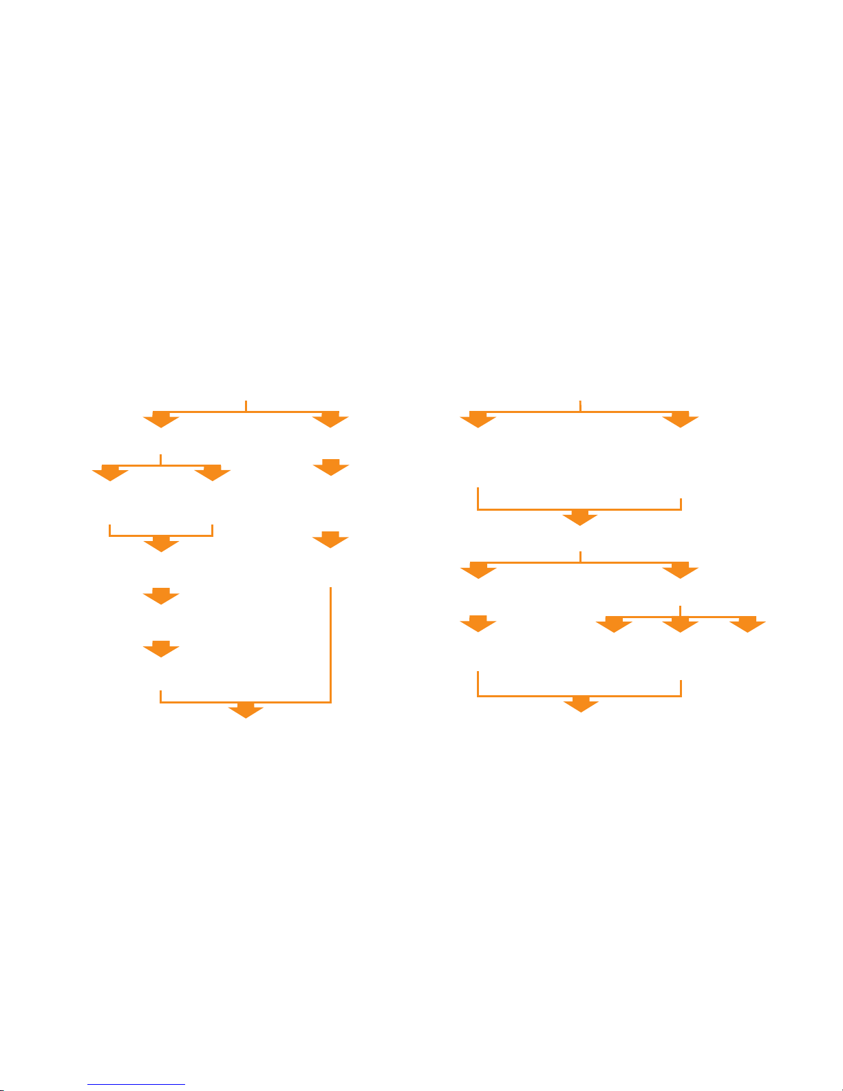
ATOM system installation overview
This section gives an overview of the steps involved in installing, setting-up and calibrating an ATOM system. More detailed information is contained within the rest of the document.
For information on designing the readhead and scale into the system refer to the detailed installation drawings and 3D models on www.renishaw.com or contact your local Renishaw representative.
IMPORTANT: Prior to installing readhead and scale, installation drawings should be reviewed to ensure correct orientation of readhead relative to scale.
Scale mounting
System connection
RTLF (tape scale)
RCLC (glass spar)
Ledge or dowel mount
<500 mm only.
See page 6.
Ledge or
dowel mount.
See page 10.
Scale applicator
Any length.
See page 7.
Fit datum clamp.
See page 8.
Fit datum clamp.
See page 10.
Deselect unused reference marks.
See page 8.
Fit end covers.
See page 8.
System connection
Calibrate system
See page 22.
No interface
Connect readhead to
customer electronics.
See page 11.
Interface
Plug readhead cable into
the interface and connect to
customer electronics.
See pages 13 to 16.
Fixed mounting
Shim kit
See page 18.
Mount and align readhead
Adjustable bracket
Signal
amplitude
adjustment.
See page 20.
Accurate
bracket.
See page 20.
Dummy head.
See page 19.
Page 6

ATO M linear installation guide
4
RTLF tape scale: Installation drawing
For dimensioned cabled and FPC readhead drawings see pages 26 and 27.
Dimensions and tolerances in mm
Measuring length = Overall length -3 mm
For detailed installation drawings refer to www.renishaw.com
0.36
0.18
0.22
(Roll tol. ±1°)
40 µm version
(Yaw tol. ±1°)
20 µm version
(Yaw tol. ±0.5°)
8
4.5
12
Scale thickness (including adhesive) 0.41
FPC ribbon cable
Scale datum edge
Datum clamp
(A-9585-0028)
(see page 8)
Set-up LED
1.02 ±0.25
0.36
(Pitch tol. ±1°)
50
50
Reference mark
Reference mark
Forward direction of readhead
relative to scale
Rideheight (for calibration):
2.5 ±0.08 (40 µm version)
2.5 ±0.04 (20 µm version)
Operating rideheight:
2.5 ±0.11 (40 µm version)
2.5 ±0.055 (20 µm version)
Readhead/scale orientation
Page 7
ATO M linear installation guide
5
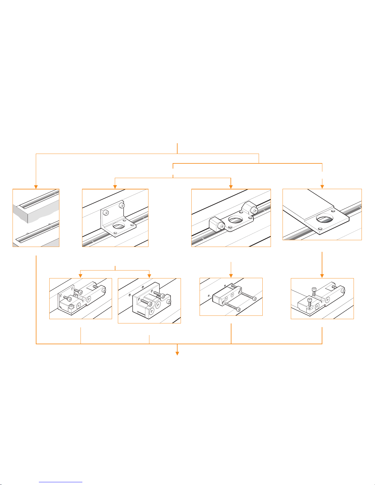
Datum edge of readhead mounted against machine axis.
For use with side mounting bracket A-9401-0103.
or customer designed bracket.
Datum edge of readhead located against a
ledge on the bracket to control yaw.
For use with ‘L’ mounting bracket A-9402-0037
or customer designed bracket.
Readhead mounting is integral to the machine and
does not allow rideheight adjustment.
Slim applicator A-9402-0060. See page 7.
Top mount applicator A-9402-0028.
See page 7.
Side mounted applicator A-9402-0034. Only for
use with ‘L’ mounting bracket A-9402-0037.
See page 7.
Top mount applicator A-9402-0028.
See page 7.
RTLF tape scale: Application methods
RTLF scale application depends upon scale length and bracket type
Mounting (<500 mm only)
RTLF tape scale
Application (any length)
Fixed mounting
Adjustable bracket
Ledge or dowel mounting.
See page 6.
Install datum clamp, end covers and deselect reference marks. See page 8.
Page 8
ATO M linear installation guide
6
Location ledge
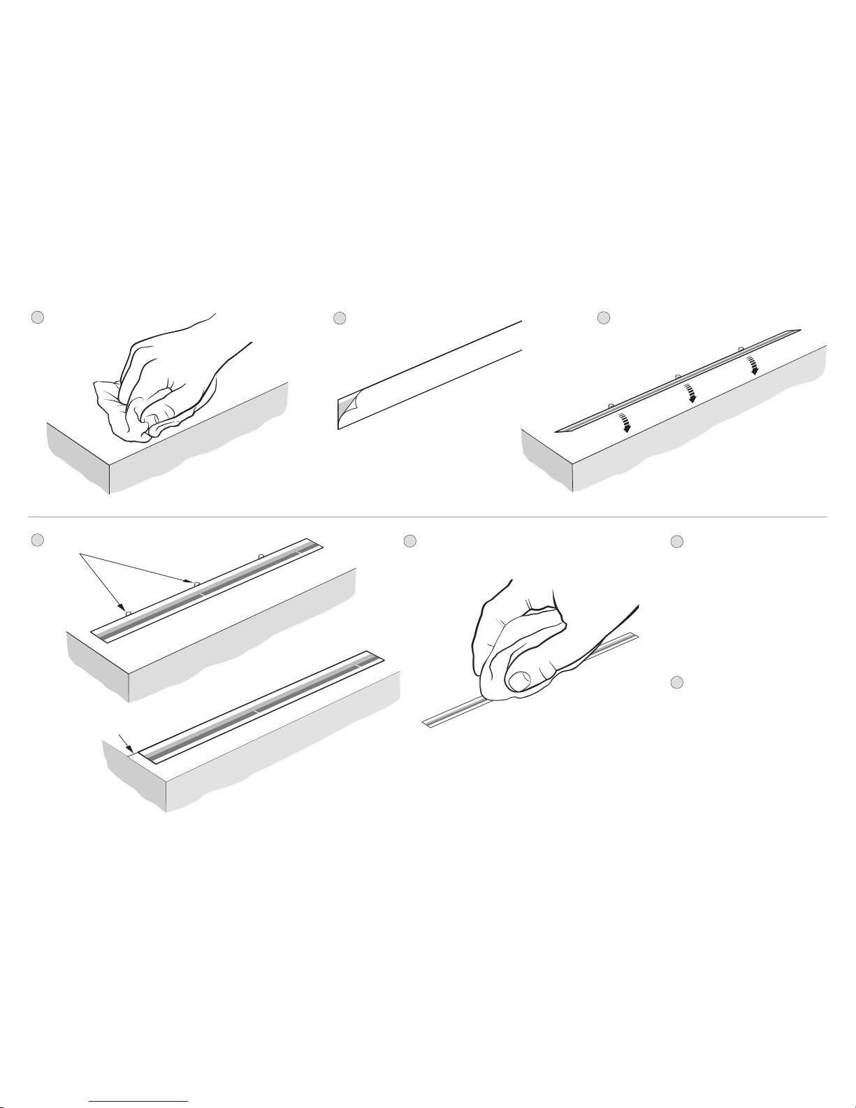
RTLF tape scale: Mounting (for lengths <500 mm only)
4
3
Locate scale against dowels or ledge
and rotate down onto substrate.
*
1
Thoroughly clean and
degrease the
substrate.
2
Remove backing paper from scale.
or
Install datum clamp, end covers and
deselect reference marks as
detailed on page 8.
6
Remove temporary dowels
(if tted).
7
5
Clean scale using Renishaw scale cleaning wipes
(A-9523-4040) or a clean, dry, lint-free cloth.
*
If dowels or ledge are permanent, their maximum
height above substrate is 0.6 mm.
Support
dowels
Page 9
ATO M linear installation guide
7
For more information on designing your bracket and mounting the
chosen scale applicator contact your local Renishaw representative.
RTLF tape scale: Application (any length)
There are three versions of applicator for use with RTLF scale
depending upon the design of the readhead mounting bracket:
Slim applicator (A-9402-0060) which is mounted in place of the
readhead bracket. It can be used in conjunction with the side
mounting bracket (A-9401-0103) or a customer designed bracket.
Top mount applicator (A-9402-0028) which is mounted in place
of the readhead. It can be used in conjunction with the
‘L’ mounting bracket (A-9402-0037) or a customer designed bracket.
Side mount applicator (A-9402-0034) which is mounted in place
of the readhead bracket. It can be used in conjunction with the
‘L’ mounting bracket (A-9402-0037) or a customer designed bracket.
Thoroughly clean and degrease the substrate.
3
4
Slim and side mount applicators:
Mount the applicator in place of the readhead bracket.
Top mount applicator:
Mount the applicator on a specically designed bracket
in place of the readhead.
2
Mark out the start position for the scale on the axis substrate.
1
Allow scale to acclimatize to installation environment
prior to installation.
Side mount applicator shown
Scale
(attached to substrate)
Limit stop
Scale
‘Splitter screw’
Backing paper
Direction of scale application
Start position
Check correct scale orientation.
6
Move axis to start of travel.
5
7
When using the top mount applicator cut the backing paper
approximately 30 mm from the end of the scale. Leaving the
end piece adhering to the scale begin to peel off the remaining
backing paper. Insert the scale into the applicator up to the
start position. Ensure the backing paper feeds out of the
back of the applicator round the splitter screw as shown.
8
Apply pressure via a clean lint free cloth to ensure scale end
adheres well to the substrate.
9
Slowly and smoothly move the applicator through the entire
length of travel, ensuring the backing paper is pulled manually
from the scale and does not catch under the applicator.
12
Clean the scale using Renishaw scale cleaning wipes
(A-9523-4040) or a clean, dry, lint-free cloth.
13
Fit datum clamp and end covers and, if needed, deselect
reference marks that are not required as detailed on page 8.
10
Remove applicator and, if necessary, adhere the remaining scale
manually. NOTE: when using the top mount applicator ensure
the backing paper left at the start of the axis is removed.
Apply a rm nger pressure via a clean lint-free cloth along the
length of the scale after application to ensure complete adhesion.
Slim and side mount applicators:
Fit readhead mounting bracket after removal of scale applicator.
11
When using the slim or side mount applicators begin
to peel off the backing paper from the end of the scale
and insert the scale into the applicator up to the start.
Ensure the backing paper feeds out of the back of the
applicator around the splitter screw as shown.
Page 10
ATO M linear installation guide
8
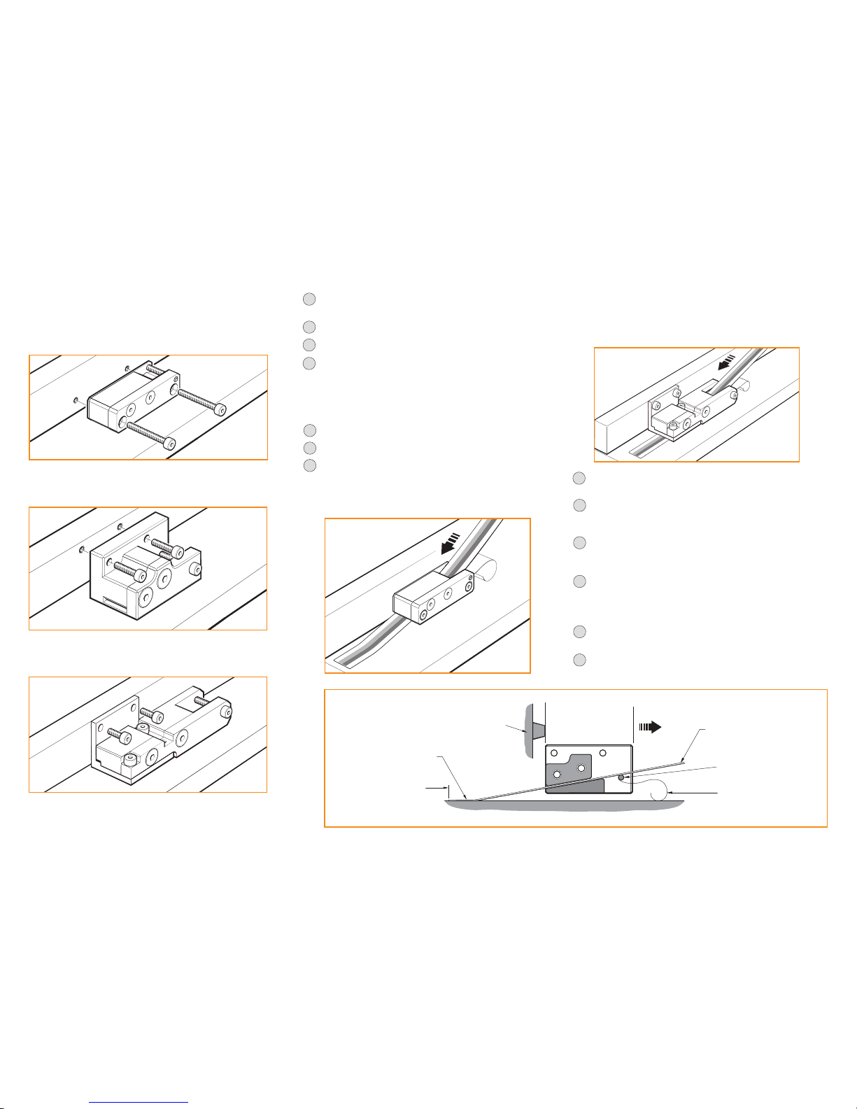
Datum clamp (A-9585-0028)
The datum clamp xes the RTLF scale rigidly to the substrate at the location chosen.
The metrology of the system may be compromised if the datum clamp is not used.
It can be positioned anywhere along the axis depending upon the customers’ requirements.
2
Align markers on the edges of the end cover with the end
of the scale and place end cover over the scale.
NOTE: There will be a gap* between
the end of the scale and the
adhesive tape on the
end cover.
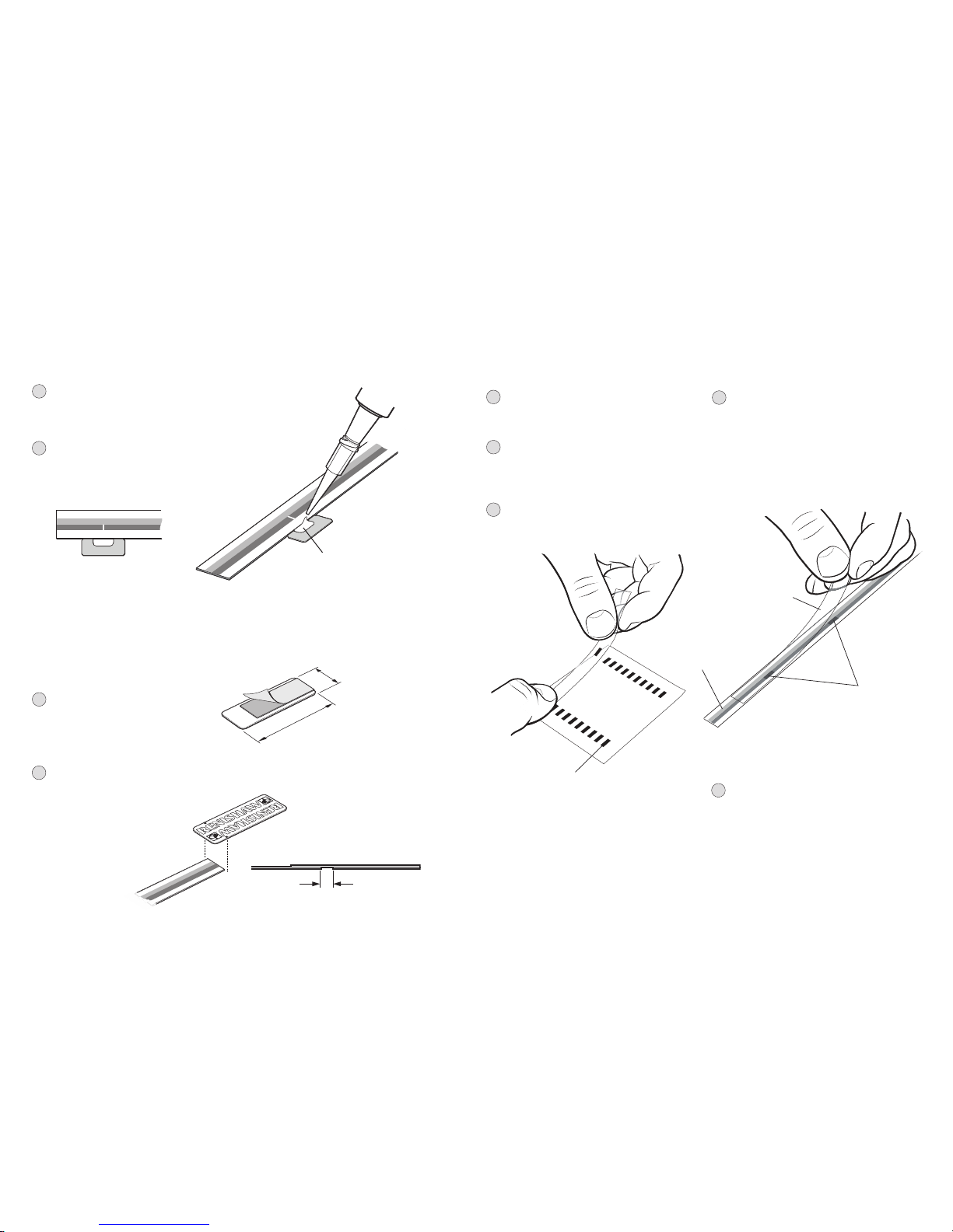
Reference mark deselection
RTLF scale >100 mm in length has reference marks every 50 mm. Stickers can be used to deselect all
unused reference marks (A-9402-0049 for a sheet of 20). The stickers are aligned on the backing paper
with a 50 mm spacing so two can be selected at once for deselecting two reference marks.
1
Ensure the scale is free from dirt and grease
by cleaning with a scale wipe (A-9523-4040)
or suitable solvent.
2
Place the transparent applicator lm over the
reference mark deselector stickers and rub rmly
until the sticker adheres to the applicator lm.
Two stickers can be selected at once.
3
Remove the applicator lm, complete with
the stickers, from the backing paper.
Self adhesive reference mark deselector
stickers on backing paper
5
Remove applicator lm.
4
Align the stickers on the scale over the
reference marks that are not required,
as shown in the diagram, then rub rmly
on the applicator lm until the stickers
adhere to the scale.
Care should be taken to ensure the stickers
fully cover the reference mark and do not
obscure any of the incremental track.
Deselected
reference marks
Applicator film
End covers
The end cover kit (A-9585-0035) is designed to be used with
RTLF scale to provide protection for exposed scale ends.
NOTE: End covers are optional and can be tted
before or after readhead installation.
1
Remove the backing paper from
the adhesive tape on the back
of the end cover.
22
8
Incremental track
Dimensions in mm
2
Place a small amount of adhesive (Loctite® 435™)
in the cut-out on the datum clamp, ensuring none
of the adhesive wicks onto the scale surface.
Dispensing tips P-TL50-0209 are available.
1
Remove the backing paper from the datum clamp.
Place the datum clamp with cut-out against the
scale at the chosen location.
Ensure the adhesive wicks along
the entire length of cut-out.
*
gap
Page 11

ATO M linear installation guide
9
For detailed installation drawings refer to www.renishaw.com
Dimensions and tolerances in mm
*Can be applied on one or both sides of the scale.
A-9404-4018
0.22
(Roll tol. ±1°)
40 µm version
(Yaw tol. ±1°)
20 µm version
(Yaw tol. ±0.5°)
6.35
6.82 ±0.25
End reference mark
Scale thickness (including adhesive) 1.1
FPC cable
Scale
datum edge
Readhead
datum face
Set-up LED
1.42 ±0.25
0.36
(Pitch tol. ±1°)
End reference mark
readhead orientation
Mid reference mark
readhead orientation
Adhesive datum clamp*
(length 8 - 16, width 1 - 5)
(A-9531-0342)
(see page 10)
L/2
5
Forward direction of readhead
relative to scale
Forward direction of readhead
relative to scale
0.36
0.18
Mid reference mark
Rideheight (for calibration):
2.5 ±0.08 (40 µm version)
2.5 ±0.04 (20 µm version)
Operating rideheight:
2.5 ±0.11 (40 µm version)
2.5 ±0.055 (20 µm version)
RCLC glass spar scale: Installation drawing
For dimensioned cabled and FPC readhead drawings see page 26 and 27.
Readhead/scale orientation
Overall length (L) 10† 18 30 55 80 100 105 130
Measuring length 7 15 27 52 77 97 102 127
†
20 µm pitch RCLC scale only.
Page 12
ATO M linear installation guide
10
Support
dowels
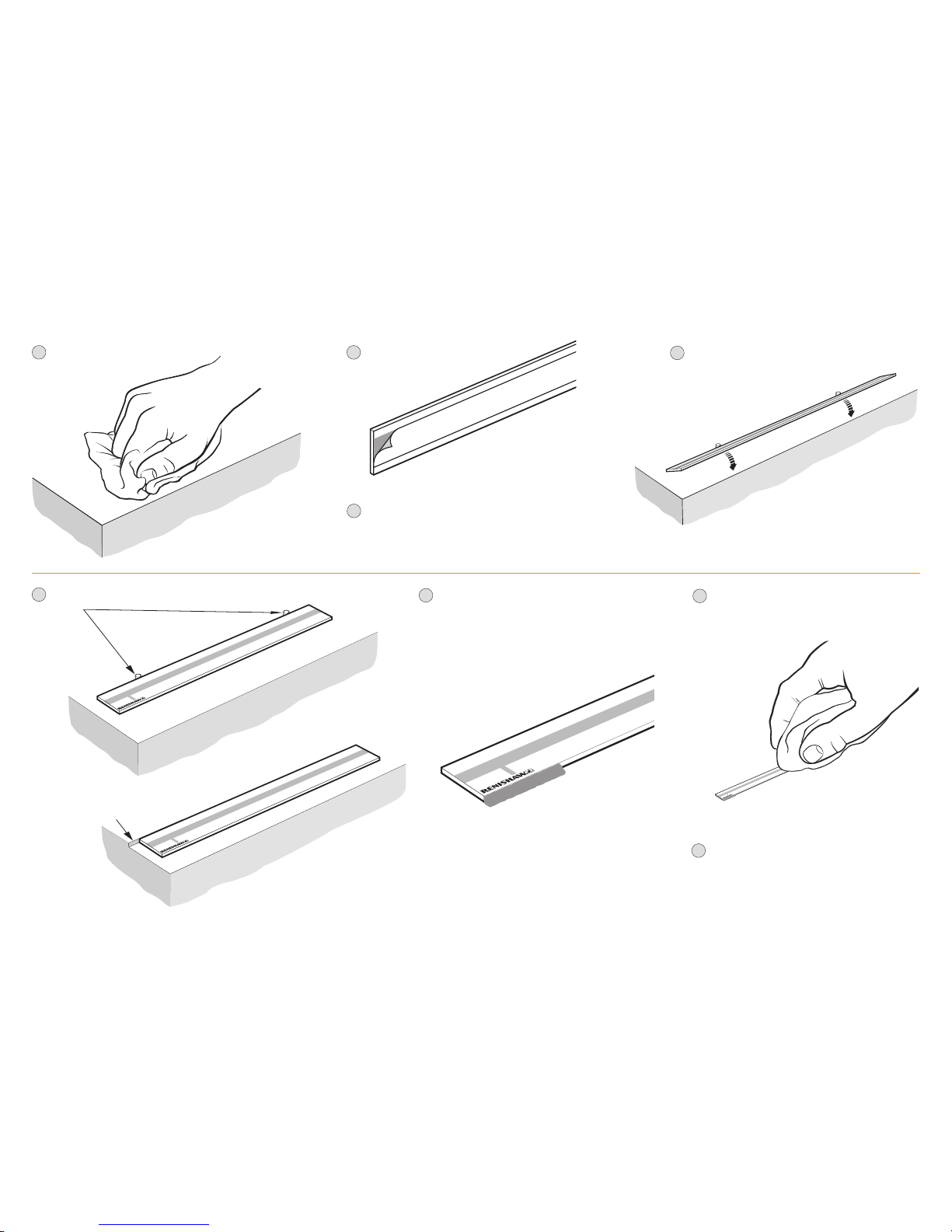
RCLC glass spar scale: Mounting
4
Locate scale against dowels or ledge
and rotate down onto substrate.*
1
Thoroughly clean and
degrease the
substrate.
2
Remove backing paper from scale.
Location ledge
5
or
After 24 hours when adhesive is cured, clean scale
using Renishaw scale cleaning wipes
(A-9523-4040) or a clean, dry, lint-free cloth.
7
Apply llet of adhesive (A-9531-0342). Adhesive can
be applied to one or both sides of the scale.
Ensure adhesive does not wick onto scale surface.
(End reference mark shown).
Datum clamp does not need to be positioned adjacent
to a reference mark. It can be positioned anywhere
along the axis depending upon the
customers’ requirements.
6
*
If dowels or ledge are permanent, their maximum height
above substrate is 1.2 mm.
Remove temporary dowels (if tted).
8
3
Ensure correct orientation of the scale for chosen
reference mark location (middle or end of scale) and
readhead orientation. See ‘RCLC glass spar scale:
Installation drawing’ for details.
Page 13
ATO M linear installation guide
11
System connection: Readhead only (no interface)
The ATOM readhead is available in several variants:
u
Cable variant with a 15 way D-type connector
u
Cable variant with interboard connector
u
FPC variant
None of these readhead variants has an integral calibration (CAL) button. Provision should be made
in the customers’ electronics for momentarily connecting the CAL line to 0 V to initiate the calibration
routine, switch AGC on/off or restore factory defaults. See page 28 for pin-out information.
Calibration is an essential part of system set-up that optimises the incremental signals and
phases the reference mark. See page 22 for information on the calibration routine.
For cable variant with interboard connector
u
Ensure that the interboard connector is inserted into the connector on the customers’ electronics
NOTE: Care should be taken to ensure correct orientation
u
Use a metal clamp around the cable ferrule to ground the readhead cable and ensure continuity
of the shields
u
Provide appropriate strain relief
u
Ensure suitable clamping to retain interboard connector to the mating connector
For FPC variants
Ensure that the FPC cable being used has the following specifications:
u
16 core
u
Conductor pitch 0.5 mm
u
Minimum exposed conductor strip length 1.5 mm
u
Maximum exposed conductor strip length 2.5 mm (to ensure isolation from the body)
Contact your local Renishaw representative for more information of the FPC design requirements.
Shielding
For optimum performance:
u
Ensure 100% shielding
u
Ground the mounting brackets
u
Ensure continuity of all shields
u
Maximise the distance between the encoder and motor cables
u
Provide appropriate strain relief at the readhead
JST 12 way,
single row
12SUR-32S
Interboard connector
14 way, dual row
DF23C-14DS- 0.5 V
1
2
13
14
Interboard
connector
PCB
FPC
connector
FPC
cable
Readhead LED
Shield
connect pad
0-0.5 mm
4 mm
Example of strain relief:
3.25 mm
Page 14

ATO M linear installation guide
12
Removing the FPC cable
1
Placing your finger on the whole of the
locking lever, slowly lift it up and away to
disengage the locking mechanism.
Do not use tools such as screwdrivers
or tweezers to open the locking lever
as this may cause damage to the
connector or pcb.
3
Pull the FPC cable straight back to remove it.
Do not pull upwards or sideways as
this may damage the readhead.
2
Ensure locking lever is fully open before
removing the FPC cable.
Inserting the FPC cable
1
Ensure the locking lever is up (open) before fully
inserting the FPC cable into the connector.
NOTE: Check correct orientation of cable before
inserting into the connector. Readhead will be
shipped with connector in the open position.
3
When the system has been connected, proceed with
‘Readhead mounting and alignment’ and
‘System calibration’ sections.
2
Applying pressure to the whole locking lever
push it down to lock the FPC cable in place.
NOTE: Do not push the locking lever down if
no FPC cable is inserted as this will damage
the locking mechanism.
The FPC cable must be connected before fitting the readhead lid. The lid is secured by the readhead mounting screws.
Approved ESD precautions must be followed at all times during readhead electrical connection.
Page 15

ATO M linear installation guide
13
System connection: ACi interface
FPC variant
Ensure that the FPC cable being used has the following specifications:
u
16 core
u
Conductor pitch 0.5 mm
u
Minimum exposed conductor strip length 1.5 mm
u
Maximum exposed conductor strip length 2.5 mm (to ensure isolation from the body)
Contact your local Renishaw representative for more information of the FPC design requirements.
Shielding
For optimum performance:
u
Ensure 100% shielding
u
Ground the mounting brackets, readhead and FPC cable clamp
u
Ensure continuity of all shields
u
Maximise the distance between the encoder and motor cables
u
Provide appropriate strain relief at the readhead and interface
u
The ACi should be contained within a shielded enclosure
Mounting
ACi can be mounted to customers’ system using 2 off M3 screws or 2 off M2.5 screws for through mounting.
Output
The output connector is a 10 way JST, GH cr imp connector with 1.25 mm pitch.
It is suitable for cable size 26 to 30 AWG. See page 29 for pin-out information.
Connection
For information on inserting and removing the FPC cable to the ACi and readhead see page 12.
Approved ESD precautions must be followed at
all times during readhead electrical connection.
The FPC cable must be connected to the readhead before fitting the lid.
The lid is secured by the readhead mounting screws.
Cable variant
Shielding
For optimum performance:
u
Ensure 100% shielding
u
Ground the mounting brackets
u
Use a metal clamp around the cable ferrule to ground the readhead cable
u
Ensure continuity of all shields
u
Maximise the distance between the encoder and motor cables
u
Provide appropriate strain relief at the readhead and interface
u
The ACi should be contained within a shielded enclosure
u
Ensure suitable clamping to retain interboard connector to the mating connector
Mounting
ACi can be mounted to customers’ system using 2 off M3 screws or 2 off M2.5 screws for through mounting.
Output
The output connector is a 10 way JST, GH cr imp connector with 1.25 mm pitch.
It is suitable for cable size 26 to 30 AWG. See page 30 for pin-out information.
Approved ESD precautions must be followed at
all times during readhead electrical connection.
PCB
PCB
FPC
cable
FPC input
connector
*
Ensure suitable clamping to retain interboard connector on ACi.
JST output
connector
2 mounting holes
M3 through
Cable
interboard
connector
*
Ferrule
Cable
interboard
connector
2 mounting holes
M3 through
JST output
connector
FPC input
connector
Pin 1
Pin 1
Page 16

ATO M linear installation guide
14
System connection: ACi interface
PCB mounting: connecting an FPC variant ATOM readhead
Ensure that the FPC cable being used has the following specifications:
u
16 core
u
Conductor pitch 0.5 mm
u
Minimum exposed conductor strip length 1.5 mm
u
Maximum exposed conductor strip length 2.5 mm (to ensure isolation from the body)
Contact your local Renishaw representative for more information of the FPC design requirements.
Shielding
For optimum performance:
u
Ensure 100% shielding
u
Ground the mounting brackets, readhead and FPC cable clamp
u
Ensure continuity of all shields
u
Maximise the distance between the encoder and motor cables
u
Provide appropriate strain relief at the readhead and interface
u
The ACi should be contained within a shielded enclosure
Connection
For information on inserting and removing the FPC cable to the mating socket see page 12.
Approved ESD precautions must be followed at
all times during readhead electrical connection.
The FPC cable must be connected to the readhead before fitting the lid.
The lid is secured by the readhead mounting screws.
PCB mounting: connecting a cable variant ATOM readhead
Shielding
For optimum performance:
u
Ensure 100% shielding
u
Ground the mounting brackets
u
Use a metal clamp around the cable ferrule to ground the readhead cable
u
Ensure continuity of all shields
u
Maximise the distance between the encoder and motor cables
u
Provide appropriate strain relief at the readhead and interface
u
The ACi should be contained within a shielded enclosure
u
Ensure suitable clamping to retain interboard connector to the mating connector
Approved ESD precautions must be followed at
all times during readhead electrical connection.
FPC input
connector
FPC cable
2 mounting holes
M3 through
Output
Customer PCB
Input
ACi interface
Ferrule
2 mounting holes
M3 through
Output
Customer PCB
Input
Cable interboard
connector
*
ACi interface
Pin 1
Pin 1
Page 17

ATO M linear installation guide
15
System connection: Ri interface
Approved ESD precautions must be followed
at all times during readhead and interface
electrical connections.
The readhead is connected to the Ri interface
via a small, rugged connector to allow for easy
feed-through during installation.
NOTE: An optional Ri cable guide (A-9693-2577)
is available to simplify assembly.
For instructions on how to install the Ri cable guide,
download ‘Ri interface cable guide’ from the website at
www.renishaw.com/encoderinstallationguides
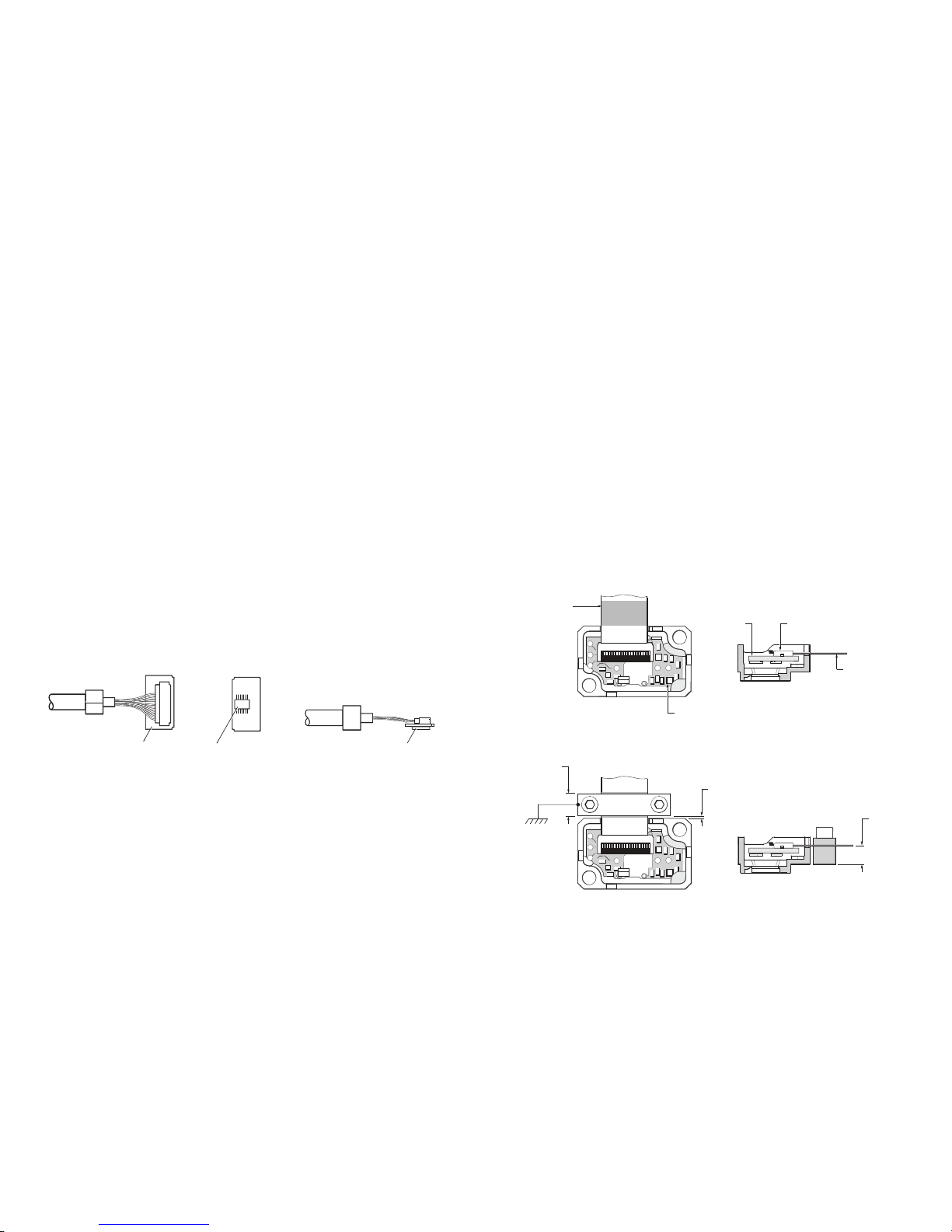
Connecting the readhead
1
Open the interface housing by removing
the 2 screws shown.
(4-40 UNC screws and nuts)
2
With the plain side uppermost,
remove the top half of the housing,
so that the interface PCB is exposed
and the readhead connection socket
is visible.
3
Taking care not to touch the pins,
plug the connector into the socket
in the interface, ensuring correct
orientation as shown.
NOTE: Care is required to hold the
assembly together as the PCB is xed
only to the 15 way connector and the
jack screws are loose.
4
Re-assemble the housing ensuring the
cable ferrule is located in the recess
on the inside and no wires are trapped.
5
Ret the screws.
6
When the system has been connected,
proceed with ‘Readhead mounting and
alignment’ and ‘System calibration’ sections
Disconnecting the readhead
1
Disconnect power.
2
Open the interface housing as detailed earlier in this section.
3
Gently lever the connector PCB (on the end of the cable)
out of the socket.
4
Place the connector in an anti-static bag.
5
Re-assemble the interface.
Readhead
connection
socket
Ensure ferrule
is located in housing
recess
Page 18

ATO M linear installation guide
16
System connection: Ti interface
Approved ESD precautions must be followed
at all times during readhead and interface
electrical connection. The readhead is
connected to the Ti interface via a small,
rugged interboard connector to allow for
easy feed-through during installation.
Connecting the readhead
1
Remove the cover plate as shown
(2 off M2.5 hex head screws).
2
Taking care not to touch the pins,
plug the connector into the
socket in the interface,
ensuring correct orientation as shown.
3
Ret the cover plate ensuring the cable ferrule is located in the recess on the inside and no wires are trapped under the cover plate.
4
When the system has been connected proceed with ‘Readhead mounting and alignment’ and ’System calibration’ sections.
Disconnecting the readhead
1
Disconnect power.
2
Remove the cover plate on the interface
(2 off M2.5 hex head screws).
3
Gently lever the connector PCB
(on the end of the cable) out of the socket.
Do not pull the cable to remove the connector.
4
Place the connector in an anti-static bag.
5
Ret the cover plate.
Page 19

ATO M linear installation guide
17
Readhead mounting and alignment: Methods
There is a range of tools available to assist with readhead installation depending upon the system design,
these are detailed below. For more details on designing the mounting bracket and selecting the appropriate
mounting tools contact your local Renishaw representative.
Ensure that the scale, readhead optical window and mounting face are clean and free from obstruction.
Do not saturate the readhead window with cleaning solvent as this may cause contamination on the inside
of the readhead window which cannot be cleaned.
NOTE: For FPC readheads the FPC cable must be tted prior to mounting the readhead. See page 12 for more details.
IMPORTANT: Whichever method is used to mount the readhead, care should be taken to ensure the scale surface is
not damaged during this operation, particularly when metal-to-metal contact is necessary.
Fixed mounting
Readhead mounting
bracket does not
allow for adjustment
of rideheight
Shim kit. See page 18.
Dummy head. See page 19.
Signal amplitude adjustment. See page 20.
Accurate bracket and feeler gauge.
See page 20.
Adjustable
bracket
Readhead mounting
bracket allows
adjustment of
rideheight
Page 20

ATO M linear installation guide
18
2
Subtract the distance measured from the
nominal rideheight of 2.5 mm to calculate
the required shim thickness.
For example if the distance measured
is 2.37 mm the required shim thickness
is 130 µm.
3
Select a combination of two shims that
gets within 10 µm of the difference.
For distances less than 100 µm a single
shim should be used, for distances greater
than 100 µm select one thick ( 100 µm)
and one thin (<100 µm) shim.
In the above example this could either be
1 x 100 µm shim and 1 x 40 µm shim or
1 x 100 µm shim and 1 x 20 µm shim.
4
Place the chosen shim(s) between the
readhead and the bracket.
5
Fix the readhead to the bracket using
2 off M2 x 6 screws in diagonally opposite
xing holes, ensuring readhead is tightened
down evenly and parallel to the bracket face.
6
Connect the system up. See pages 11 to 16
for relevant system connection
7
Check the readhead set-up LED is Green
along the full axis of travel.
8
Proceed with ‘System calibration’ section.
1
Using a digital dial gauge or similar measure
the distance from the readhead mounting
surface to the scale surface.
Care must be taken to ensure the scale
surface is not scratched.
Renishaw offer a DTi adapter (A-9401-0105)
that can be used to assist with this process.
– Insert the gauge into the adapter and
zero the gauge on a at surface.
– Position or x the gauge/adapter in
place of the readhead and measure
the distance to the scale surface.
Contact your local Renishaw representative
for details of the DTi adapter and digital
dial guage.
Shim kit (A-9401-0050)
This method is intended for
applications where the
rideheight of the readhead
cannot be adjusted.
The system should be designed to achieve a
nominal distance of 2.3 mm (±0.2 mm) from
the readhead mounting surface to the top of
the scale.
Shims of a known thickness are inserted between the mounting face of the readhead and the
bracket to give the correct rideheight.
The kit consists of:
2.3 ±0.2 mm
Readhead mounting surface
Part Number:
A-9401 A-9401 A-9401 A- 9401 A-9401 A- 9401 A-9401
-0041 -0042 -0043 -0044 - 0045 - 0046 -0047
Thickness (µm) 20 40 60 80 100 200 300
Quantity in pack 10 10 10 10 20 20 10
DTi adapter
Readhead
mounting
surface
Page 21

ATO M linear installation guide
19
5
Remove the dummy head.
6
Install the ATOM readhead in place of the dummy head using M2 x 6 screws in diagonally opposite
xing h oles. Ensure the readhead is pushed back against the shoulder of the bracket or mounting face.
4
Tighten the bracket xing screws whilst ensuring good contact between the ‘nose’ of the dummy head
and the surface of the scale.
7
Connect the system up. See pages 11 to 16 for relevant system connection.
9
Proceed with ‘System calibration’ section.
8
Check the readhead set-up LED is Green along the full axis of travel.
Dummy head (A-9401-0072)
The reuseable dummy head has the same dimensions as the ATOM readhead
with a longer ‘nose’ that is machined to the optimum rideheight (2.5 mm ±0.02 mm).
It is mounted in place of the readhead directly onto the bracket.
The bracket should have a shoulder to control readhead yaw.
Contact your local Renishaw representative for more information on bracket design.
1
Mount the dummy head onto the bracket using 2 off M2 x 6 screws.
3
Adjust the height of the bracket until the ‘nose’ of the dummy head touches the scale.
2
Loosely mount the readhead bracket onto the axis.
Slim mount bracket
A-9401-0103
Shoulder
‘L’ mount bracket
A-9402-0037
Page 22

ATO M linear installation guide
20
Accurate bracket and feeler gauge
Fix the readhead directly onto a mounting bracket with a thickness of 2 ±0.02 mm
then use a 0.5 mm feeler gauge to set the rideheight.
NOTE: Bracket A-9401-0103 is not suitable for this installation method.
For more information on system tolerances refer to the installation drawings on www.renishaw.com.
For more information on bracket design contact your local Renishaw representative.
1
Mount the readhead onto the bracket using 2 off M2 x 6 screws.
2
Loosely mount the readhead bracket onto the axis.
3
Place the feeler gauge between the readhead bracket and the scale.
4
Tighten the bracket xing screws whilst ensuring good contact between bracket, shim and
surface of the scale.
5
Connect the system up. See pages 11 to 16 for relevant system connection.
6
Check the readhead set-up LED is Green along the full axis of travel.
7
Proceed with ‘System calibraton’ section.
Signal amplitude adjustment
Mount the readhead directly onto a bracket, then, using the Renishaw USB set-up tool kit and software
or oscilloscope, adjust the readhead to maximise the signal size.
For more information on bracket design and the Renishaw USB set-up tool kit contact your local
Renishaw representative.
For more information on system tolerances refer to the installation drawings on www.renishaw.com
1
Mount the readhead onto the bracket using 2 off M2 x 6 screws.
2
Loosely mount the readhead bracket onto the axis.
3
Using the Renishaw USB set-up tool kit or an oscilloscope adjust the yaw, pitch and
rideheight of the readhead to maximise the signal strength.
4
Tighten the bracket and readhead xing screws.
5
Connect the system up. See pages 11 to 16 for relevant system connection.
6
Check the readhead set-up LED is Green along the full axis of travel.
7
Proceed with ‘System calibraton’ section.
Feeler gauge
Rideheight
Rideheight
Pitch
Ya w
Page 23

ATO M linear installation guide
21
Calibration overview
Calibration is an essential operation that completes readhead set-up, with the optimum incremental and reference mark signal settings stored in the readhead’s non-volatile memory.
This section is an overview of the calibration procedure for an ATOM system.
More detailed information on calibrating the system is on page 22.
The system is now calibrated and ready for use.
AGC can now be switched on if required.
NOTE: If calibration fails (readhead set-up LED continues ashing Blue),
restore factory defaults and repeat the calibration routine.
No reference mark
Manually exit calibration routine.
The readhead set-up LED will stop ashing Blue.
Reference mark
Move the readhead back and forth over the chosen reference mark
until the readhead set-up LED stops ashing Blue.
Ensure AGC is switched off.
Systems are shipped with AGC switched off.
When AGC is switched off the readhead set-up LED will be Green, Orange or Red.
Align the readhead to maximise signal strength over the full length of travel.
The readhead set-up LED will be Green.
Initiate Incremental signal calibration routine.
The readhead set-up LED will be single ashing Blue.
Move the readhead along the axis at slow speed (<100 mm/s).
The readhead set-up LED will start double ashing Blue.
Page 24

ATO M linear installation guide
22
System calibration (CAL)
Calibration is an essential operation that completes readhead set-up, with the optimum incremental
and reference mark signal settings stored in the readhead’s non-volatile memory.
Before system calibration:
uClean the scale and readhead optical window
uIf reinstalling, restore factory defaults
uEnsure AGC is switched off (readhead set-up LED is Green, Red or Orange)
uMaximise the signal strength along full length of travel (readhead set-up LED is Green)
NOTE: CAL routine maximum speed <100 mm/s
Step 1 – Incremental signal calibration
uInitiate calibration routine.
u The readhead set-up LED will now periodically single-ash Blue to indicate that it is in the incremental
signal calibration routine. The set-up signal (VX) will be a nominal 0 V.
u Slowly move the readhead along the axis, ensuring you do not pass a reference mark, until the readhead
set-up LED starts double-ashing Blue. This indicates the incremental signal is now calibrated and the
new settings are stored in the readhead memory. The set-up signal (VX) will be a nominal 1.65 V.
u The system is now ready for reference mark phasing.
u For systems without reference mark, go to ‘Calibration routine - manual exit’
u If the system does not automatically enter the reference mark phasing stage (no double-ashing Blue
of the readhead set-up LED) the calibration of the incremental signals has failed. After ensuring failure
is not due to overspeed (>100 mm/s), exit the calibration routine, restore factory defaults and check the
readhead installation and system cleanliness before repeating the calibration routine.
Step 2 – Reference mark phasing
u Slowly move the readhead back and forth over the chosen reference mark until the readhead set-up
LED stops ashing and remains Green. The reference mark is now phased. The set-up signal (VX) will
be a nominal 3.3 V depending upon system set-up (see interface output specications for more details).
NOTE: Only the chosen reference mark that has been used in the calibration routine is guaranteed to
remain phased.
u The system automatically exits the CAL routine and is ready for operation.
u If the readhead set-up LED continues double-ashing Blue after passing the chosen reference mark
many times, it is not detecting the reference mark. Ensure that the readhead orientation and lateral
offset are correct.
Calibration routine – manual exit
u The calibration routine can be exited at any stage. Depending upon the interface used follow the relevant
section in the table below to exit CAL mode.
uOn successful exit the readhead set-up LED will stop ashing Blue and remain Green or Red.
Restoring factory defaults
When realigning the readhead, reinstalling the system, or in the case of continued calibration failure,
factory defaults should be restored.
To restore factory defaults:
u Switch system off, then switch on again using the following methods depending on interface used.
u The readhead set-up LED will ash Blue four times on switch on.
u Release CAL button, CAL pads link or CAL pin ground.
u Check the ‘Readhead mounting /installation’ and recalibrate the system.
NOTE: System must be recalibrated after restoring factory defaults.
Switching Automatic Gain Control (AGC) on or off
AGC can be switched on or off via the interface or the CAL line.
u The readhead set-up LED will be Green with the addition of Blue when AGC is enabled.
NOTE: The system must be calibrated before switching AGC on.
No interface
Ground and hold the
CAL pin whilst switching
the system on.
ACi interface
Connect the CAL pads
together or ground the
remote CAL line (pin 8) whilst
switching the system on.
Ri interface
Press and hold the CAL
button on the side of the
interface whilst switching
the system on.
Ti interface
Press and hold the
CAL button on the end
of the interface whilst
switching the system on.
No interface
Ground the CAL pin for
<2 seconds.
ACi interface
Connect the CAL pads
together or ground the
remote CAL line (pin 8) for
<2 seconds.
Ri interface
Press and hold the CAL
button on the side of the
interface for <2 seconds.
Ti interface
Press the CAL button on
the end of the interface for
<2 seconds.
No interface
Ground the CAL pin for
>3 seconds then remove
ground link.
Ri interface
Press and hold the CAL
button on the side of the
interface for >3 seconds
then release.
ACi interface
Connect the CAL pads
together or ground the
remote CAL line (pin 8) for
>3 seconds then disconn ect.
Ti interface
Press and hold the CAL
button on the end of the
interface for >3 seconds
then release.
Ti interface
Press the CAL button
on the end of the
interface for
<2 seconds
using a
2 mm
allen key or
similar tool.
WARNING! Activating the CAL
switch only requires 2.5 N force.
Applying excess force may
permanently damage the switch.
No interface
Ground the
CAL pin for
<2 seconds
ACi interface
Connect the CAL pads
together or ground the
remote CAL line (pin 8)
for <2 seconds
Ri interface
Press the CAL button
on the side of the
interface for
<2 seconds
using a
2 mm
allen key or
similar tool.
WARNING! Activating the CAL
switch only requires 2.5 N force.
Applying excess force may
permanently damage the switch.
CAL
button
2 CAL
pads
Page 25

ATO M linear installation guide
23
Ti interface
* Alarm output will take the form of 3-state or line driven E- signal depending on interface conguration.
Also, some congurations do not output overspeed alarm. See product nomenclature for details.
-Momentary status only, while fault condition remains.
-Alarm may result in axis position error, re-datum to continue.
Normal setup; signal level 110% to 135%
Optimum setup; signal level 90% to 110%
Normal set-up: signal level 70% to 90%
Acceptable set-up; signal level 50% to 70%
Poor set-up; signal may be too low for reliable operation;signal level <50%
Poor set-up; signal level <20%; system in error
Over speed; system in error
Over signal; system in error
Reference mark detected (speed <100 mm/s only)
Status
Indication
Signal
Purple
Blue
Green
Orange
Red
Red / blank - ashing
Blue / blank - ashing
Purple / blank - ashing
Blank ash
Incremental
Reference mark
Alarm output*
No
No
No
No
No
Ye s
Ye s
Ye s
No
*When stationary will be Green or Red.
=
Flash will effectively be invisible when incremental signal level is >70% when passing reference mark.
‡
When AGC is enabled the LED indication will be as shown but with the addition of a Blue indication.
Normal set-up; signal level >70%, AGC off
Acceptable set-up; signal level 50% to 70%, AGC off
Poor set-up; signal may be too low for reliable operation; signal level <50%, AGC off
Calibrating incremental signals
Calibrating reference mark
Normal phasing
Acceptable phasing
Poor phasing; clean scale and recalibrate if required
Factory defaults restored
Status
Indication
Green
Orange*
Red
Single Blue ashing
Double Blue ashing
Green (ash)
=
Blank (ash)
Red (ash)
4 Blue ashes on switch on
Incremental
(AGC off)
‡
CAL
Reference mark
Restore factory defaults
Signal
LED diagnostics
Readhead
The readhead set-up LED consists of a tri-coloured LED which can display any combination of Red, Blue or Green.
Page 26

ATO M linear installation guide
24
Troubleshooting
LED on the readhead is Blank
LED on the readhead is Red and I can’t
get a Green LED
Unable to get a Green LED over the
complete axis length
Can’t initiate the calibration routine
LED on the readhead remains single
ashing Blue even after moving it along
the full axis length
LED on the readhead appears Purple
There is no power to the readhead
The signal strength is <50%
System run-out is not
within specication
Cabled D-type readhead does not
have CAL button
The system has failed to calibrate the
incremental signals due to the signal
strength being <70% before the
calibration routine was initiated
This is Blue and Red combined
AGC is switched on and
signal level is <50%
Fault Cause
Possible solutions
u
Ensure 5 V supplied at the readhead
u
For cable variants check correct wiring of connector
NOTE: Analogue and digital systems have different pin-outs
u
When using Ti, Ri or cabled ACi interfaces check the interboard connector that plugs in the interface is
properly seated and the correct orientation
u
For FPC variants check correct insertion and orientation of the FPC cable
u
Check the readhead optical window and scale are clean and free from contamination
u
Restore factory defaults (see page 22) and check alignment of the readhead. In particular;
– Rideheight
– Ya w
– Offset
u
Check the scale and readhead orientation
u
Check that the readhead variant is the correct type for the chosen scale
(see the data sheet for details of readhead conguration)
u
Check that the readhead variant is the correct type for the chosen scale
(see the data sheet for details of readhead conguration)
u
Use a DTi gauge and check the run-out is within specications
u
Restore factory defaults
u
Realign readhead to obtain a Green LED at the mid-point of the run-out
u
Recalibrate the system (see page 22)
u
If not using an interface with a CAL button check that the correct pin is being shorted to 0 V for <2 seconds
u
Check that the signal size is >70% before initiating calibration
u
Exit CAL mode and restore factory defaults (see page 22)
u
Check system set-up and realign the readhead to obtain a Green LED along the full axis of travel
before recalibrating
u
Check the readhead optical window and scale are clean and free from contamination
u
Restore factory defaults (see page 22) then check the LED is Green along the full axis and recalibrate
the system (see page 22). If it is not Green check the alignment of the readhead
Page 27

ATO M linear installation guide
25
Troubleshooting (continued)
LED on the readhead appears white with
ashes of other colours as the readhead is
moved along the axis
LED on the readhead is double ashing
Blue even after moving it past the
reference mark several times
No reference mark output
Reference mark is not repeatable
LED on the readhead is ashing Red or
Blank over the reference mark
Multiple reference marks output
Fault Cause
u
Check the readhead optical window and scale are clean and free from contamination
u
Restore factory defaults (see page 22) then check the LED is Green along the full axis and recalibrate
the system (see page 22). If it is not Green check the alignment of the readhead
u
Ensure you are moving the readhead past your chosen reference mark several times
u
Check the scale/readhead orientation
u
Check the scale readhead alignment
u
Check the readhead optical window and scale are clean and free from contamination
u
Check that the readhead variant is the correct type for the chosen scale
(see the data sheet for details of readhead conguration)
u
Ensure you are not over-speeding the readhead during calibration mode (maximum speed <100 mm/sec)
u
Calibrate the system (see page 22)
– If the system completes calibration mode then it has successfully seen and calibrated the reference mark
If you still don’t see a reference mark then check the system wiring
– If the system does not calibrate the reference mark (LED on the readhead double ashes Blue)
see above for possible solutions
u
Ensure you are using the reference mark that has been calibrated for referencing your system
u
The readhead bracket must be stable and not allow any mechanical movement of the readhead
u
Check any unused reference marks have been deselected
u
Clean the scale and readhead optical window and check for damage then recalibrate the system over
the chosen reference mark
u
Ensure you are using the reference mark that has been calibrated for referencing your system as only this
reference mark will be guaranteed to remain phased.
The LED may ash Blank or Red when passing other reference marks if they have not been deselected
(see page 8)
u
Clean the scale and readhead optical window and check for scratches then recalibrate the system over the
chosen reference mark (see page 22)
u
All unused reference marks should be deselected (see page 8) as only the calibrated reference mark will be repeatable
u
Check alignment of deselection stickers
u
Replace damaged FPC (if applicable)
Possible solutions
AGC is switched on and
the signal level is <70%
The readhead is not seeing a
reference mark
Only the chosen reference mark that has
been used in the calibration sequence is
repeatable, other reference marks may
not be phased
The reference mark is not phased
Unused reference marks have not
been deselected or FPC is damaged
Page 28

ATO M linear installation guide
26
ATOM readhead: Cabled readhead dimensions
Dimensions and tolerances in mm
6.45
1.4 (40 µm version)
1.9 (20 µm version)
20.5
16.5
10.25
12.7
8.7
2
4.15
4.85*
3 off mounting holes
Ø2.5 min through
Ø9 max
Set-up
LED
Mounting face
Readhead
datum faces
5 min
Ø
3.5 max
R>20 Dynamic bend radius
R>10 Static bend radius
2
Readhead/scale
orientation
Identification marks for readhead manufacture only.
Notches will vary depending on readhead type.
For detailed installation drawings refer to www.renishaw.com
*Not optical centreline
Page 29

ATO M linear installation guide
27
ATOM readhead: FPC readhead dimensions
Dimensions and tolerances in mm
4.15
NOTE: Readhead is supplied with lid separate. FPC cable must be inserted before fitting the lid.
For detailed installation drawings refer to www.renishaw.com
1.4 (40 µm version)
1.9 (20 µm version)
20.5
16.5
10.25
12.7
8.7
2
5.4
4.85*
2 off mounting holes
Ø2.5 min through
Ø9 max
FPC ribbon cable
Set-up
LED
Mounting face
Readhead
datum faces
2
Readhead/scale
orientation
8.5
4.4
Identification marks for readhead manufacture only.
Notches will vary depending on readhead type.
3.25
*Not optical centreline
Page 30

ATO M linear installation guide
28
ATOM readhead: Output signals
15 way D-type plug
Interboard connector for
connection to Ri,Ti and
cabled ACi interfaces
1
2
13
14
FPC connection
Pin 1
JST connector
Pin 1
Pin 12
*All power connections should be used either to minimise voltage drop down the cable or incorporate voltage sensing.
=
Only available on interboard connector
Power*
Incremental
Reference mark
Set-up
Remote CAL
Shield
Do not connect
Function
Signal
Cosine
Sine
Colour
Brown
White
Red
Blue
Yellow
Green
Violet
Grey
Clear
Orange
Screen
–
5 V
0 V
V
1
V2
V
0
+
-
+
-
+
-
VX
CAL
–
–
Interboard connector
(T)
FPC
(F)
Pin
4
13
9
5
12
14
2
8
6
10
Cable ferrule
1, 3, 7, 11
Pin
9, 10
3, 6, 11, 14
5
4
2
1
13
12
16
15
Readhead body
7, 8
JST=
(on interboard)
Pin
11
5
4
3
7
6
10
9
12
8
Cable ferrule
1, 2
15 way D-type
(D)
Pin
4, 5
12, 13
9
1
10
2
3
11
6
14
Case
7, 8, 15
Page 31

ATO M linear installation guide
29
14.5
25
4.5 x 45°
2
6
10
25
7.7
9.5
4
4.6
5.6
5.6
15.75
12.5
17
2 mounting holes
M3 through
CAL pad
CAL pad
2 mounting
pillars
JST output
connector
*
6.25
FPC input connector
=
4
Pin1
Pin1
Output signals
Pin 1 Pin 10
ACi JST output connector
Pin 1 Pin 16
ACi FPC input connector
Component area
Component area
Component area
ACi interface: FPC variant
Installation drawing
Dimensions and tolerances in mm
Signal
JST connector
A-9412-1001 cable
(15 way D type)
Pin
Function
Power
Incremental
Reference mark
Set-up
Remote CAL
9
10
1
2
3
4
5
6
7
8
7, 8
2, 9
14
6
13
5
12
4
1
11
5 V
0 V
A
B
Z
+
-
+
-
+
-
X
CAL
Input signals
*All power connections should be used either to minimise voltage drop down the cable or incorporate voltage sensing.
Signal
Pin
Function
Power*
Incremental
Reference mark
Set-up
Remote CAL
Do not connect
7, 8
3, 6, 11, 14
12
13
15
16
4
5
1
2
9, 10
5 V
0 V
V1
V2
V
0
+
-
+
-
+
-
VX
CAL
–
*10 way JST, GH crimp connector. 1.25 mm pitch. Suitable for cable size 26 to 30 AWG. 3 m JST to 15 way D-type cable A-9412-1001
=
NOTE: Care must be taken not to damage the FPC connector when tting/removing the cable.
FPC connector
=
FPC cable
Page 32

ATO M linear installation guide
30
Input signals
*All power connections should be used either to minimise voltage drop down the cable or incorporate voltage sensing.
=
Only available on interboard connector
Power*
Incremental
Reference mark
Set-up
Remote CAL
Shield
Do not connect
Function
Signal
Cosine
Sine
Colour
Brown
White
Red
Blue
Yellow
Green
Violet
Grey
Clear
Orange
Screen
–
5 V
0 V
V
1
V2
V
0
+
-
+
-
+
-
VX
CAL
–
–
Interboard
connector
(T)
Pin
4
13
9
5
12
14
2
8
6
10
Cable ferrule
1, 3, 7, 11
JST=
(on interboard)
Pin
11
5
4
3
7
6
10
9
12
8
Cable ferrule
1, 2
Readhead cable input connector
JST connector
Pin 1
Pin 12
9
Interboard connector for
connection to Ri, Ti and
cabled ACi interfaces
1
2
13
14
15
9.5
6.25
2.5
14.5
25
4.5 x 45°
2
6
5
25
9.5
4
4.6
5.6
5.6
15.75
17
2 mounting holes
M3 through
CAL pad
CAL pad
2 mounting
pillars
JST output
connector
*
6.25
Cable input connector
Pin1
Component area
Component area
Component area
10
2.5
7.7
4
*10 way JST, GH crimp connector. 1.25 mm pitch. Suitable for cable size 26 to 30 AWG.
3 m JST to 15 way D-type cable A-9412-1001
ACi interface: Cable variant
Installation drawing
Dimensions and tolerances in mm
Output signals
Signal
JST connector
A-9412-1001 cable
(15 way D type)
Pin
Function
Power
Incremental
Reference mark
Set-up
Remote CAL
9
10
1
2
3
4
5
6
7
8
7, 8
2, 9
14
6
13
5
12
4
1
11
5 V
0 V
A
B
Z
+
-
+
-
+
-
X
CAL
Pin 1 Pin 10
ACi JST output connector
4
21 ±1
Cable ferrule nominal diameter
5.9 ±0.2 mm
Page 33

ATO M linear installation guide
31
ACi interface: PCB mounting variant
Installation drawing
Dimensions and tolerances in mm
16.1
10.1
25
4.5 x 45°
25
4
4
5.6
5.6
12.5
17
2 mounting holes
M3 through
CAL pad
CAL pad
Component area
Component area
5.6
14.5
ACi PCB mounting variant interface (digital output only)
Function
Power
Incremental
Reference mark
Set-up
Remote CAL
Signal
Pin
9
2
4
6
3
1
8
10
7
5
5 V
0 V
V1
V2
V
0
+
-
+
-
+
-
V
X
CAL
Input
Signal
Pin
6
5
8
10
7
9
3
1
4
2
5 V
0 V
A
B
Z
+
-
+
-
+
-
X
CAL
Output
Pin 1
ACi PCB input
connector
Pin 2
Pin 9
Pin 10
Pin 1
ACi PCB output
connector
Pin 2
Pin 9
Pin 10
Recommended mating connector - Samtec CLP-105-02-F-D-P-TR
PCB footprint
1.27
1.27 (typ)
0.74 (typ)
Clearance holes
∅ 0.74
0.5
4.7
(Samtec FTS-105-01-L-DV-P-TR)
Page 34

ATO M linear installation guide
32
Lowest recommended
counter input frequency
(MHz)
Maximum speed (m/s)
0020
(2 µm)
13
13
–
13
–
8
–
0040
(1 µm)
13
13
–
8
–
4
–
0080
(0.5 µm)
13
8
–
4
–
2
–
40
20
12
10
6
5
4
0100
(0.4 µm)
11.6
6.4
–
3.2
–
1.6
–
0200
(0.2 µm)
6
3.2
–
1.6
–
0.8
–
0400
(0.1 µm)
–
–
0.7
–
0.36
–
0.24
1000
(40 nm)
–
–
0.26
–
0.12
–
0.08
2000
(20 nm)
–
–
0.13
–
0.06
–
0.04
40 µm system
ACi interface: Speed
Lowest recommended
counter input frequency
(MHz)
Maximum speed (m/s)
0020
(1 µm)
6.5
6.5
–
6.5
–
4
–
0040
(0.5 µm)
6.5
6.5
–
4
–
2
–
0080
(0.25 µm)
6.5
4
–
2
–
1
–
0100
(0.2 µm)
5.8
3.2
–
1.6
–
0.8
–
0200
(0.1 µm)
3
1.6
–
0.8
–
0.4
–
0400
(50 nm)
–
–
0.35
–
0.18
–
0.12
1000
(20 nm)
–
–
0.13
–
0.06
–
0.04
2000
(10 nm)
–
–
0.065
–
0.03
–
0.02
40
20
12
10
6
5
4
20 µm system
Page 35

ATO M linear installation guide
33
15
1
8
9
CAL button operation
Push and release (<2 seconds) - Calibration (CAL) routine initiation/exit
Push and release (>3 seconds) - Automatic Gain Control (AGC) initiation/exit
Push and hold during power ‘Off/On’ cycle - Restore factory defaults
40
6 min
33.3
R>10 Static bend radius
R>20 Dynamic bend radius
8
4- 40 UNC x 2
52
16
CAL button
access hole
Ø3.15
Ri interface: Interface drawing
Dimensions and tolerances in mm
*
All power connections should be used either to minimise voltage drop down the cable or incorporate voltage sensing.
†
The alarm signal can be output as a line driver signal or 3-state.
Please select the preferred option at time of ordering.
Power*
Incremental
Reference mark
Set-up
Remote CAL
Shield
Do not connect
Function
Signal
Cosine
Sine
5 V
0 V
VX
CAL
–
–
V1
V2
V
0
+
-
+
-
+
-
Pin
4, 5
12, 13
9
1
10
2
3
11
6
14
Case
7, 8, 15
Analogue
Output signals
Digital
Signal
Pin
Function
Power*
Incremental
Reference mark
Alarm
†
Set-up
Shield
Do not connect
7, 8
2, 9
14
6
13
5
12
4
11
3
1
Case
10, 15
5 V
0 V
A
B
Z
E
+
-
+
-
+
-
+
-
X
–
–
Page 36

ATO M linear installation guide
34
Ri interface: Speed
Clocked outputs
Ri0100, Ri0200 and Ri0400 interfaces have clocked outputs.
Customers must ensure they comply with the lowest recommended counter input frequency.
Lowest recommended counter
input frequency
(MHz)
Maximum speed (m/s)
0100
(0.2 µm)
–
–
0.8
0.5
0200
(0.1 µm)
0.8
0.5
0.4
0.25
0400
(50 nm)
0.4
0.25
0.2
0.12
12
10
6
4
20 µm system
40 µm system
0100
(0.4 µm)
–
–
1.6
1.0
0200
(0.2 µm)
1.6
1.0
0.8
0.5
0400
(0.1 µm)
0.8
0.5
0.4
0.24
Non-clocked outputs
Ri0004, Ri0008, Ri0020 and Ri0040 interfaces have non-clocked outputs.
Lowest recommended counter
input frequency
(MHz)
20 µm system
40 µm system
Encoder velocity (m/s)
Resolution (µm)
x 4
safety
factor
Interface
type
0004 (5 µm)
0008 (2.5 µm)
0020 (1 µm)
0040 (0.5 µm)
Maximum
speed
(m/s)
10
10
10
10
Interface
type
0004 (10 µm)
0008 (5 µm)
0020 (2 µm)
0040 (1 µm)
Maximum
speed
(m/s)
20
20
20
20
Analogue speed
40 µm system – 20 m/s (-3dB)
20 µm system – 10 m/s (-3dB)
Page 37

ATO M linear installation guide
35
CAL button operation
Push and release (<2 seconds) - Calibration (CAL) routine initiation/exit
Push and release (>3 seconds) - Automatic Gain Control (AGC) initiation/exit
Push and hold during power ‘Off/On’ cycle - Restore factory defaults
Refer to ‘Readhead LED diagnostics’ and ‘Ti LED diagnostics’ for LED indications
*
All power connections should be used either to minimise voltage drop down the cable or incorporate voltage sensing.
†
Alarm output will take the form of 3-state or line driven E signal depending on interface configuration.
Please select the preferred option at time of ordering.
Power*
Incremental
Reference mark
Set-up
Remote CAL
Shield
Do not connect
Function
Signal
Cosine
Sine
5 V
0 V
VX
CAL
–
–
V1
V2
V
0
+
-
+
-
+
-
Pin
4, 5
12, 13
9
1
10
2
3
11
6
14
Case
7, 8, 15
Analogue
Output signals
Digital
Signal
Pin
Function
Power*
Incremental
Reference mark
Alarm
†
Set-up
Shield
Do not connect
7, 8
2, 9
14
6
13
5
12
4
11
3
1
Case
10, 15
5 V
0 V
A
B
Z
E
+
-
+
-
+
-
+
-
X
–
–
8
15
1
8
9
16
4- 40 UNC x 2
40
6 min
62
67
CAL button access hole Ø2.4
33.3
Interface set-up LED
(
digital interface only
)
Cover plate
R>20 Dynamic bend radius
R>10 Static bend radius
Ti interface: Interface drawing
Dimensions and tolerances in mm
Page 38

ATO M linear installation guide
36
Lowest recommended
counter input frequency
(MHz)
50
40
25
20
12
10
8
6
4
1
Maximum speed (m/s)
0004
(10 µm)
20
20
20
20
20
20
20
20
20
8.4
0020
(2 µm)
20
20
20
20
18
16.2
12.96
9
6.74
1.68
0040
(1 µm)
20
20
16.2
13.5
9
8
6.48
4.5
3.36
0.84
0100
(0.4 µm)
12.96
10.8
6.48
5.4
3.6
3.24
2.58
1.8
1.34
0.32
0200
(0.2 µm)
6.48
5.4
3.24
2.7
1.8
1.62
1.296
0.9
0.676
0.168
0400
(0.1 µm)
3.25
2.7
1.62
1.34
0.9
0.8
0.648
0.45
0.338
0.084
1000
(40 nm)
1.296
1.08
0.648
0.54
0.36
0.324
0.26
0.18
0.136
0.034
2000
(20 nm)
0.648
0.54
0.324
0.27
0.18
0.162
0.13
0.09
0.068
0.016
4000
(10 nm)
0.324
0.27
0.162
0.136
0.09
0.082
0.064
0.046
0.034
0.008
10KD
(4 nm)
0.013
0.108
0.064
0.054
0.036
0.032
0.026
0.018
0.0136
0.0034
20KD
(2 nm)
0.064
0.054
0.032
0.026
0.018
0.0162
0.013
0.009
0.0068
0.0016
40 µm system
Lowest recommended
counter input frequency
(MHz)
50
40
25
20
12
10
8
6
4
1
Maximum speed (m/s)
0004
(5 µm)
10
10
10
10
10
10
10
10
10
4.2
0020
(1 µm)
10
10
10
10
9
8.1
6.48
4.5
3.37
0.84
0040
(0.5 µm)
10
10
8.1
6.75
4.5
4.05
3.24
2.25
1.68
0.42
0100
(0.2 µm)
6.48
5.4
3.24
2.7
1.8
1.62
1.29
0.9
0.67
0.16
0200
(0.1 µm)
3.24
2.7
1.62
1.35
0.9
0.81
0.648
0.45
0.338
0.084
0400
(50 nm)
1.62
1.35
0.81
0.675
0.45
0.405
0.324
0.225
0.169
0.042
1000
(20 nm)
0.648
0.54
0.324
0.27
0.18
0.162
0.13
0.09
0.068
0.017
2000
(10 nm)
0.324
0.27
0.162
0.135
0.09
0.081
0.065
0.045
0.034
0.008
4000
(5 nm)
0.162
0.135
0.081
0.068
0.045
0.041
0.032
0.023
0.017
0.004
10KD
(2 nm)
0.0654
0.054
0.032
0.027
0.018
0.016
0.013
0.009
0.0068
0.0017
20KD
(1 nm)
0.032
0.027
0.016
0.013
0.009
0.0081
0.0065
0.0045
0.0034
0.0008
20 µm system
Analogue speed
20 µm system – 10 m/s (-3dB)
40 µm system – 20 m/s (-3dB)
Ti interface: Speed
Page 39

ATO M linear installation guide
37
Analogue outputs
V0 V1 V2-
V
0
V1 V2+
120R
Remote CAL operation
CAL
0 V
Remote CAL operation is possible
via the CAL pin.
For applications where no interface is used,
remote CAL operation is essential.
Recommended signal termination
Digital outputs
Interface
A B Z E+
Cable Z0 = 120R
Customer
electronics
A B Z E-
120R
Electrical connections
Grounding and shielding
IMPORTANT: The shield should be connected to the machine earth (Field Ground).
NOTE: Maximum cable length between interface and customer electronics is
25 m for ACi and Ri and 50 m for Ti.
(Maximum length for Ti with 40 or 50 MHz clocked output is 25 m).
Cable readhead
Shield
Output
signals
5 V
Connector/
interface
0 V
Customer
electronics
FPC readhead
FPC cable
Shield
(recommended)
Output
signals
5 V
0 V
ACi/ customer
electronics
For more information on FPC contact your local Renishaw representative.
Standard RS422A line receiver circuitry.
Capacitors recommended for improved noise immunity.
0 V
0 V
220 pF
220 pF
Page 40

ATO M linear installation guide
38
Output specications
Analogue output signals
All ATOM readheads and Ri and Ti analogue interfaces
Digital output signals
Form – Square wave differential line driver to EIA RS422A All ACi interfaces and Ri and Ti digital interfaces
Incremental† 2 channels A and B in quadrature (90° phase shifted)
Reference
†
Signal period
Resolution
A
B
Z
Synchronised pulse Z, duration as resolution
Incremental 2 channels V1 and V2 differential sinusoids in quadrature,
centred ~ 1.65 V (90° phase shifted)
Bi-directionally repeatable
Differential pulse V
0
centred on 45°
Reference
(V0 +)-(V0-)
1 Vpp
360° (nom)
0.7 to 1.35 Vpp with green
LED indication (readhead)
and 120R termination.
40/20 µm
(V1 +)-(V1 -)
(V2 +)-(V2 -)
0°
Set-up* (Ti digital only)
Voltage
at X
1
100%
0
0
Signal level
Setup signal voltage proportional to incremental signal amplitude
>15 ms
E
*
Set-up signals as shown are not present
during calibration routine
†
Inverse signals not shown for clarity
3-state alarm (ACi, Ri and Ti digital)
Differentially transmitted signals forced open circuit for >15 ms when alarm conditions valid.
(Ri and Ti alarm conditions as detailed above. ACi alarm conditions: <40% signal or overspeed)
Alarm† Differential line driven output (Ri and Ti digital)
Line driven
Interface
model
Ri0004
Ri0008
Ri0020
Ri0040
Ri0100
Ri0200
Ri0400
<20% signal
or
>130% signal
<40% signal
or
overspeed
Alarm asserted
when
Interface
model
Ti
<20% signal
or
>135% signal
or
overspeed
Alarm asserted
when
Between 50% and 70% signal level, VX is a duty cycle, 20 µm duration.
Time spent at 3.3 V increases with incremental signal level.
At >70% signal level VX is nominal 3.3 V.
Voltage at
V
X
3.3 V (nom)
50%
70%
100%0
0
Signal level
Set-up (Readhead, Ri and Ti analogue)
During normal operation
During CAL routine (Readhead, Ri analogue and Ti analogue only)
Voltage
at V
X
Normal operation Normal operationReference
mark
calibration
3.3 V
1.65 V
0 V
Start of
calibration
routine
End of
incremental
calibration
routine
End of
calibration
routine
Incremental
calibration
>70% signal >70% signal
(after CAL)
45°
Differential signals V0+ and V0- centred on ~ 1.65 V
Between 50% and 70% signal level, X is a duty cycle, 20 µm duration.
Time spent at 3.3 V increases with incremental signal level.
At >70% signal level X is nominal 3.3 V.
Voltage at
X
3.3 V (nom)
50%
70%
100%0
0
Signal level
Set-up (ACi and Ri digital)
During normal operation
Page 41

Scale specications
RTLF
Material Hardened and tempered martensitic stainless steel tted with a
self-adhesive backing tape
Form (H x W)
0.41 mm x 8 mm (including adhesive)
Datum xing
Adhesive datum clamp A-9585-0028
secured with Loctite 435
Reference mark Customer deselectable reference marks at 50 mm spacing
Reference mark in the centre for lengths <100 mm
Auto-phase optical reference mark repeatable to unit of resolution
throughout specied speed and temperature range.
Accuracy (at 20 °C)
Coefcient of 10.1 ±0.2 µm/m/°C
thermal expansion
(at 20 °C)
Length* 10 mm to 90 mm in 10 mm increments
100 mm to 10 m in 50 mm increments
Mass 12.2 g/m
RCLC scale
Material Soda lime glass tted with a self-adhesive backing tape
Form (H x W) 1.1 mm x 6.35 mm
(including adhesive)
Datum xing
Fillet of adhesive
Reference mark Auto-phase optical reference mark repeatable to unit of resolution
throughout specied speed and temperature range.
Either mid or end of
travel, determined by orientation of the readhead.
Accuracy (at 20 °C)
Coefcient of ~8 µm/m/°C
thermal expansion
Length (mm) 10, 18, 30, 55, 80, 100, 105, 130
Mass 13.9 g/m
=
For information on scale and readhead part numbers refer to the ATOM data sheet.
*For information on how the substrate affects your axis contact your local Renishaw representative.
General specications
Power supply 5 V ±10% ATOM readhead typically <50 mA
ATOM with ACi typically <100 mA
ATOM with Ri typically <100 mA
ATOM with Ti typically <200 mA
NOTE: Current consumption gures refer to unterminated systems.
For analogue outputs a further 10 mA in total will be drawn when terminated
with 120R. For digital outputs a further 25 mA per channel pair (eg A+, A-)
will be drawn when terminated with 120R.
Power from a 5 V dc supply complying with the requirements for SELV or
standard IEC BS EN 60950-1
Ripple 200 mVpp maximum@frequency up to 500 kHz
Temperature Storage -20 °C to +70 °C
Operating 0 °C to +70 °C
Humidity 95% relative humidity (non-condensing) to EN 60068-2-78
Sealing Cable variant IP40 Ri interface IP20
FPC variant IP20 (with lid tted) Ti interface IP20
Acceleration Operating 400 m/s², 3 axes
(scale and readhead)
Shock (scale and readhead) Operating 1000 m/s², 6 ms, ½ sine, 3 axes
Vibration Operating 100 m/s² max @ 55 Hz to 2000 Hz, 3 axes
Mass FPC readhead 2.3 g Cable readhead 4 g
Cable 18 g/m ACi 4 g
Ri 70 g Ti 100 g
Readhead cable 10 core, high ex, EMI screened cable
Outside diameter 3.5 mm maximum
Flex life >20 x 106 cycles at 20 mm bend radius
Maximum length 5 m
(Extension cable up to 10 m when using Renishaw approved extension cable)
UL recognised
FPC cable 16 core, 0.5 mm pitch
Minimum exposed conductor length 1.5 mm
Maximum exposed conductor length 2.5 mm
Maximum length 1 m
Connector options Cable variants Interboard connector compatible with the Ri, Ti and ACi (cable variant)
series interfaces
15 way, D-type connector
FPC 16 core, 0.5 mm pitch, compatible with ACi (FPC variant)
Typical SDE (analogue) 40 µm version <±120 nm
20 µm version < ±75 nm
Renishaw encoder systems have been designed to the relevant EMC standards, but must be correctly
integrated to achieve EMC compliance. In particular, attention to shielding arrangements is essential.
40 µm
(high accuracy)
40 µm
20 µm
±5 µm/m
±15 µm/m
±5 µm/m
A-9408-xxxx
A-9407-xxxx
A-9406-xxxx
ATOM4x0-xxx
ATOM4x0-xxx
ATOM2x0-xxx
Accuracy
Scale part number
=
Compatible readhead
=
Scale pitch
40 µm
20 µm
±3 µm
±3 µm
A-9404-4xxx
A-9404-2xxx
ATOM4x1-xxx
ATOM2x1-xxx
Accuracy
Scale part number
=
Compatible readhead
=
Scale pitch
ATO M linear installation guide
39
Page 42

Renishaw plc
New Mills, Wotton-under-Edge,
Gloucestershire GL12 8JR
United Kingdom
T +44 (0)1453 524524
F +44 (0)1453 524901
E uk@renishaw.com
www.renishaw.com
For worldwide contact details,
please visit our main website at
www.renishaw.com/contact
*M-9693-9723-05*
RENISHAW and the probe symbol used in the RENISHAW logo are registered trade marks
of Renishaw plc in the United Kingdom and other countries.
apply innovation and names and designations of other Renishaw products and technologies
are trade marks of Renishaw plc or its subsidiaries.
Loctite® is a registered trademark of the Henkel Corporation.
2013-2016 Renishaw plc All rights reser ved Issued 0618
 Loading...