

Page 1
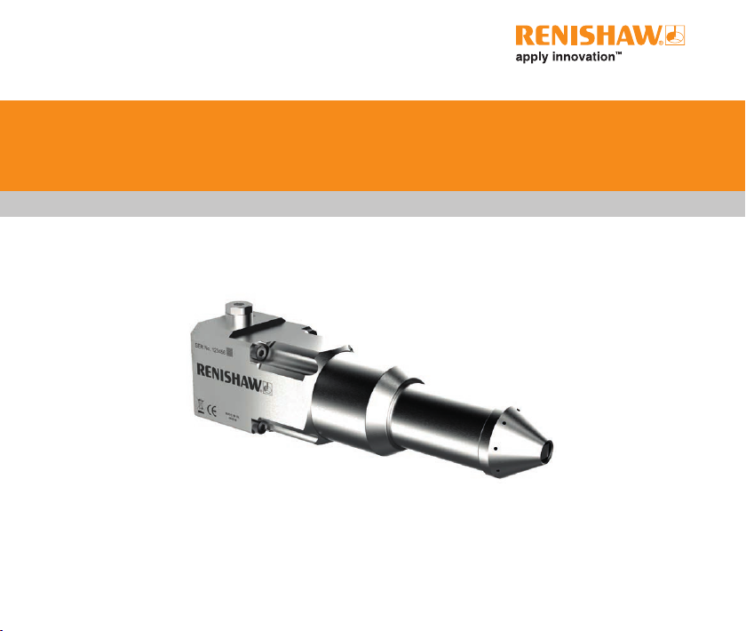
Installation and user’s guide
H-6596-8500-01-B
APCA-45 – tool setting probe
Page 2

Page 3

EN
DE
ES
FR
IT
日本語
CS
中文
(繁體)
中文
(简体)
한국어
Publications for this product are available by visiting www.renishaw.com/apc.
Weitere Informationen zu diesem Produkt sind unter folgendem Link
www.renishaw.de/apc abrufbar.
Las publicaciones para este producto están disponibles a través de
www.renishaw.es/apc.
Les documentations pour ce produit sont disponibles en visitant le site
www.renishaw.fr/apc.
La documentazione per questo prodotto è disponibile visitando il sito
www.renishaw.it/apc.
本製品に関する資料は、www.renishaw.jp/apc からダウンロードいただけます。
Dokumentaci k produktu najdete na www.renishaw.cz/apc.
請造訪 www.renishaw.com.tw/apc 網站以獲得此產品的相關文件檔案。
请访问雷尼绍网站以获得此产品的相关文档:www.renishaw.com.cn/apc。
이 제품 관련 자료는 www.renishaw.co.kr/apc에서 확인할 수 있습니다.
Page 4

This page is intentionally left blank.
Page 5

Contents
Before you begin ................................................................................................................ iv
Disclaimer ...................................................................................................................... iv
Trade marks ................................................................................................................... iv
Warranty ..........................................................................................................................v
Changes to equipment .................................................................................................... v
CNC machines ................................................................................................................ v
Care of the APCA-45 ...................................................................................................... v
Patents ............................................................................................................................ v
EU declaration of conformity .......................................................................................... vi
WEEE directive .............................................................................................................. vi
REACH regulation .......................................................................................................... vi
Product marking ............................................................................................................. vi
FCC information to user (USA only)............................................................................... vi
Safety .............................................................................................................................vii
Information to the user .............................................................................................vii
Information for the machine supplier .......................................................................vii
Warnings ........................................................................................................................vii
Equipment operation .....................................................................................................xiv
i
APCA-45 system
Introduction ............................................................................................................... 1
Interface unit
Installing the interface unit ........................................................................................ 4
..................................................................................................................1
........................................................................................................................ 3
Page 6

ii Contents (continued)
Specication ........................................................................................................................ 5
Dimensions
Preparing the machine for APCA-45 for installation
Introduction ..................................................................................................................... 8
Acceptable orientation of the APCA-45 ..........................................................................9
Connecting the APCA-45 to an HSI interface and the CNC ............................................10
Connecting the APCA-45 to an HSI-C interface and the CNC ....................................... 11
Probe inhibit function
Pneumatic options
Introduction ................................................................................................................... 13
Dual Air – air bleed........................................................................................................14
Installation
.......................................................................................................................... 7
........................................................ 8
.......................................................................................................12
............................................................................................................ 13
Dual Air – air bleed (circuit 1) .................................................................................15
Operation sequence (circuit 1)................................................................................16
Dual Air – air bleed (circuit 2) .................................................................................17
Operation sequence (circuit 2)................................................................................18
.........................................................................................................................19
Connecting the APCA-45 .......................................................................................20
Mounting the APCA-45 to the machine ..................................................................20
Fitting the stylus ...................................................................................................... 21
Page 7

iiiContents (continued)
Stylus alignment ................................................................................................................22
Stylus level setting ........................................................................................................22
Operating procedure
To operate the APCA-45 ............................................................................................... 24
Service and Maintenance
Service .......................................................................................................................... 25
Maintenance .................................................................................................................25
Cleaning instructions .....................................................................................................26
Fault-nding
Parts list
....................................................................................................................... 27
.............................................................................................................................28
......................................................................................................... 24
.................................................................................................25
Page 8

iv
Before you begin
© 2019 Renishaw plc. All rights reserved.
This document may not be copied or reproduced in whole
or in part, or transferred to any other media or language,
by any means, without the prior written permission of
Renishaw plc.
The publication of material within this document does not
imply freedom from the patent rights of Renishaw plc.
Disclaimer
RENISHAW HAS MADE CONSIDERABLE EFFORTS
TO ENSURE THE CONTENT OF THIS DOCUMENT
IS CORRECT AT THE DATE OF PUBLICATION BUT
MAKES NO WARRANTIES OR REPRESENTATIONS
REGARDING THE CONTENT. RENISHAW EXCLUDES
LIABILITY, HOWSOEVER ARISING, FOR ANY
INACCURACIES IN THIS DOCUMENT.
Renishaw part no: H-6596-8500-01-B
Issued: 04.2019
Trade marks
RENISHAW and the probe symbol used in the
RENISHAW logo are registered trade marks of Renishaw
plc in the United Kingdom and other countries. apply
innovation and names and designations of other
Renishaw products and technologies are trade marks of
Renishaw plc or its subsidiaries.
All other brand names and product names used in this
document are trade names, trade marks, or registered
trade marks of their respective owners.
Page 9

vBefore you begin (continued)
Warranty
Equipment requiring attention under warranty must be
returned to your equipment supplier.
Unless otherwise specically agreed in writing between
you and Renishaw, if you purchased the equipment from
a Renishaw company, the warranty provisions contained
in Renishaw’s CONDITIONS OF SALE apply. You should
consult these conditions in order to nd out the details of
your warranty but, in summary, the main exclusions from
the warranty are if the equipment has been:
• neglected, mishandled or inappropriately used; or
• modified or altered in any way except with the prior
written agreement of Renishaw.
If you purchased the equipment from any other supplier,
you should contact them to nd out what repairs are
covered by their warranty.
Changes to equipment
Renishaw reserves the right to change specications
without notice.
CNC machines
CNC machine tools must always be operated by fully
trained personnel in accordance with the manufacturer’s
instructions.
Care of the APCA-45
Keep system components clean (for more information
see “Service and maintenance” on page 25).
Patents
Patents pending.
Page 10
vi
Before you begin (continued)
EU declaration of conformity
C
Renishaw plc declares under its sole responsibility that
the APCA-45 is in conformity with all relevant Union
legislation.
The full text of the EU declaration of conformity is
available at:
www.renishaw.com/mtpdoc
WEEE directive
The use of this symbol on products and/or accompanying
documentation indicates that the product should not
be mixed with general household waste upon disposal.
It is the responsibility of the end user to dispose of
this product at a designated collection point for waste
electrical and electronic equipment (WEEE) to enable
reuse or recycling. Correct disposal of this product
will help to save valuable resources and prevent
potential negative effects on the environment. For more
information, please contact your local waste disposal
service or distributor.
REACH regulation
Information required by Article 33(1) of Regulation (EC)
No. 1907/2006 (“REACH”) relating to products containing
substances of very high concern (SVHCs) is available at:
www.renishaw.com/REACH
Product marking
Please refer to markings on the product for year of
manufacture.
FCC information to user (USA only)
47 CFR Section 15.19
This device complies with Part 15 of the FCC rules.
Operation is subject to the following two conditions:
1. This device may not cause harmful interference, and
2. This device must accept any interference received,
including interference that may cause undesired
operation.
47 CFR Section 15.21
The user is cautioned that any changes or modications,
not expressly approved by Renishaw plc or authorised
representative, could void the user’s authority to operate
the equipment
.
Page 11

Before you begin (continued)
vii
47 CFR Section 15.105
This equipment has been tested and found to comply with
the limits for a Class A digital device, pursuant to part 15
of the FCC Rules. These limits are designed to provide
reasonable protection against harmful interference when
the equipment is operated in a commercial environment.
This equipment generates, uses and can radiate
radio frequency energy and, if not installed and used
in accordance with this installation guide, may cause
harmful interference to radio communications. Operation
of this equipment in a residential area is likely to cause
harmful interference, in which case you will be required to
correct the interference at your own expense.
Safety
Information to the user
In all applications involving the use of machine tools or
CMMs, eye protection is recommended.
Information for the machine supplier
It is the machine supplier’s responsibility to ensure that
the user is made aware of any hazards involved during
operation, including those mentioned in Renishaw
product literature, and to ensure that adequate guards
and safety interlocks are provided.
Under certain circumstances, the probe signal may
falsely indicate probe seated condition. Do not rely on
probe signals to halt the movement of the machine.
The automatic probe cover (APCA-45) system must
be installed by a competent person, observing relevant
safety precautions. Before starting work, ensure that
the machine tool is in a safe condition with the power
switched OFF and the power supply to the HSI or HSI-C
disconnected.
Warnings
The following residual risks of this device need to be
managed to an acceptable level by the integrator:
• Noise levels: this device emits noise as an essential
part of its operation and has been measured at
76dB.
• Pinch point: when this device operates there is a
pinching hazard between the stylus cube and the
cover
• Care must be taken when installing or cleaning the
product inside the machine tool to ensure sharp
objects are avoided.
• Ejection of debris: when air bleed is activated debris
(including metal particles) can be ejected from the
cover
Page 12

viii
Before you begin (continued)
• Installation of this pneumatically powered device
presents foreseeable pneumatic and mechanical
hazards so should only be installed by a competent
person.
• The noise level, pinch point and air bleed hazards
identified above will need to be managed during
maintenance of the machine or this device.
General warnings
GB - safety
• In all applications involving the use of machine tools
or CMMs, eye protection is recommended.
• Remove power before performing any maintenance
operations.
• It is the machine supplier’s responsibility to ensure
that the user is made aware of any hazards involved
in operation, including those mentioned in Renishaw
product documentation, and to ensure that adequate
guards and safety interlocks are provided.
• Under certain circumstances the probe signal may
falsely indicate a probe-seated condition. Do not rely
on probe signals to stop machine movement.
• The expected method of providing an emergency
stop for Renishaw products is to remove power.
BG - Раздел по безопасност
•
Препоръчва се защита на очите във всички
приложения, включващи използване на машини
или CMM.
• Преди извършване на всякакви операции по
поддръжката да се изключва захранването.
• Отговорност на доставчика на машината е
да гарантира, че на потребителя са обяснени
всякакви рискове по време на работа,
включително онези, упоменати в документацията
на продуктите Renishaw и да гарантира
осигуряване на съответни предпазители и
обезопасителни блокировки.
• При определени обстоятелства сигналът от
пробника може да посочва фалшиво състояние
на опрян пробник. Да не се разчита на сигналите
от пробника за спиране движението на машината.
• Очакваният метод за осигуряване на аварийно
спиране за продуктите Renishaw е да се изключи
захранването.
CS - Upozornění
• Při jakékoli práci s obráběcími stroji nebo
souřadnicovými měřicími stroji (CMM) je doporučeno
používat ochranu očí.
Page 13

Before you begin (continued)
ix
• Před započetím jakékoliv údržby zařízení odpojte
napájení.
• Povinností dodavatele stroje je informovat uživatele o
nebezpečích spojených s provozem i o nebezpečích
zmiňovaných v dokumentaci k produktům
společnosti Renishaw a zajistit dostatečné ochranné
a bezpečnostní systémy.
• Za určitých okolností může signál sondy nesprávně
označovat klidový stav sondy. Nevyužívejte signály
sondy jako hlavní impuls pro zastavování stroje.
• Předpokládaným způsobem nouzového zastavení
produktů společnosti Renishaw je odpojení napájení.
DA - Sikkerhed
• I alle tilfælde, hvor der anvendes værktøjs- og
koordinatmålemaskiner, anbefales det at bære
beskyttelsesbriller.
• Afbryd strømforsyningen, før der foretages vedligeholdelse.
• Det er maskinleverandørens ansvar at sikre, at brugeren er bekendt med eventuelle risici i forbindelse
med driften, herunder de risici, som er nævnt i Renishaws produktdokumentation, og at sikre, at der er
tilstrækkelig afskærmning af sikkerhedsblokeringer.
• Under visse omstændigheder kan sondesignalet ved
en fejl angive, at sonden står stille. Stol ikke på, at
probesignaler vil stoppe maskinens bevægelse.
• Den forventede metode til nødstop af Renishaw
produkter er afbrydelse strømforsyningen.
EL - Ασφάλεια
• Σε όλες τις εφαρμογές που συνεπάγονται τη χρήση
εργαλείων μηχανημάτων και εξαρτημάτων CMM,
συνιστάται η χρήση συσκευής προστασίας των
ματιών.
• Αποσυνδέστε το μηχάνημα από το ηλεκτρικό
ρεύμα πριν επιχειρήσετε οποιεσδήποτε εργασίες
συντήρησης.
• Αποτελεί ευθύνη του προμηθευτή του μηχανήματος
να εξασφαλίσει ότι ο χρήστης είναι ενήμερος για
τυχόν κινδύνους που συνεπάγεται η λειτουργία,
συμπεριλαμβανομένων όσων αναφέρονται στα
εγχειρίδια του προϊόντος της Renishaw. Είναι
επίσης ευθύνη του να εξασφαλίσει ότι υπάρχουν
τα απαιτούμενα προστατευτικά καλύμματα και οι
συνδέσεις ασφαλείας.
• Υπό ορισμένες συνθήκες το σήμα του ανιχνευτή
μπορεί να υποδεικνύει λανθασμένη ένδειξη
τοποθέτησης του ανιχνευτή. Μη βασίζεστε στα
σήματα ανιχνευτή για τη διακοπή της κίνησης του
μηχανήματος.
Page 14

x
Before you begin (continued)
• Η αναμενόμενη μέθοδος διακοπής έκτακτης ανάγκης
για τα προϊόντα Renishaw είναι η αποσύνδεσή τους
από το ηλεκτρικό ρεύμα.
ET - Ohutusosa
• Masina ja materjalidega töötamisel on alati soovitav
kanda silmade kaitset.
• Enne hooldustoimingute teostamist ühendage seade
alati vooluvõrgust lahti.
• Masina tarnija vastutuseks on tagada, et kasutajat
teavitatakse masina tööga kaasnevatest ohtudest, kaasa arvatud need ohud, mida on mainitud
Renishaw toote dokumentides, ning samuti tagada,
et masinaga oleks kaasas korrektsed kaitsepiirded
ja turvalukud.
• Teatud tingimustel võib sondi signaal ekslikult näidata, nagu oleks sond paigale asetunud. Ärge lähtuge
masina liikumise peatamisel sondi signaalidest.
• Esmaseks masina hädaseiskamise meetodiks Renishaw toodete puhul on elektritoite katkestamine.
FI - Turvallisuus
• Silmäsuojainten käyttö on suositeltavaa kaikkia
työstökoneita ja koordinaattimittauskoneita (CMM)
käytettäessä.
• Katkaise virta ennen huoltotoimenpiteiden suorit-
tamista.
• Koneen toimittajan vastuulla on, että käyttäjä on
saanut tiedon mahdollisista käyttöön liittyvistä vaaroista mukaan lukien Renishaw’n tuoteselosteessa
mainitut vaarat. Konetoimittajan tulee myös varmistaa, että suojukset ja turvalukitukset ovat riittävät.
• Tietyissä olosuhteissa anturilta tuleva signaali
saattaa virheellisesti osoittaa, että mitta-anturi on
lepotilassa (=ei-kosketuksessa). Älä pysäytä koneen
liikettä mittapään signaalien perusteella.
• Renishaw-tuotteiden hätäpysäytys tehdään taval-
lisesti kytkemällä virta pois päältä.
IRL - Rannóg sábháilteachta
• Moltar cosaint do na súile i ngach aon fheidhmiú
lena mbaineann úsáid uirlisí meaisín nó CMM.
• Bain an chumhacht de sula ndéantar aon oibríochtaí
cothabhála.
• Is í freagracht sholáthraí an mheaisín í a chinntiú
go gcuirtear an t-úsáideoir ar an eolas i leith aon
ghuaiseacha a bhaineann leis an oibriúchán, lena
n-áirítear iad siúd a luaitear i gcáipéisíocht táirge
Renishaw, agus a chinntiú go soláthraítear sciatha
cosanta agus idirghlais sábháilteachta leordhótha-
nacha.
Page 15

Before you begin (continued)
xi
• Féadtar toisc bhréagach tóireadóra-shuite a léiriú i
roinnt cúinsí le comhartha an tóireadóra féin. Ná bí
ag brath ar chomharthaí tóireadóra le gluaiseacht an
mheaisín a stopadh.
• Is é an modh a bhítear ag dúil le stop éigeandála a
sholáthar do tháirgí Renishaw ná an chumhacht a
bhaint díobh.
HU - Figyelem
• Szerszámgépek és KMG-ek használata során ajánlatos szemvédőt viselni.
• Mielőtt bármilyen karbantartási művelet végezne,
kapcsolja ki a berendezést.
• A gép szállítója felelős azért, hogy felhívja a
felhasználó figyelmét az üzemeltetéssel kapcsolatos veszélyforrásokra, ideértve az illető Renishaw
termék dokumentációjában ismertetetteket is, és
hogy gondoskodjon a megfelelő védőburkolatok és
biztonsági reteszelések meglétéről.
• Bizonyos körülmények között a mérőtapintó azt
jelezheti, hogy a mérőtapintó felfeküdt a mérendő
objektumon, noha ez nincs így. Ezért a gép
mozgásának leállításakor nem szabad a mérőtapintó
jeleire hagyatkozni.
• A Renishaw termékek vészleállításának elvárt mód-
szere a berendezés kikapcsolása.
HR - Sigurnosnim
• Kod svih primjena koje uključuju upotrebu alatnih
strojeva ili CMM-ova preporučuje se zaštita očiju.
• Isključite napajanje prije provođenja bilo kakvih
radova održavanja.
• Dobavljač stroja dužan je osigurati da korisnik bude
upozoren na sve opasnosti tijekom rada, uključujući
one navedene u dokumentaciji proizvoda Renishaw,
te mora osigurati odgovarajuće zaštite i sigurnosne
blokade.
• Pod određenim okolnostima signal sonde može
lažno pokazivati stanje položaja sonde.
• Očekivana metoda omogućavanja zaustavljanja u
nuždi za proizvode Renishaw je isključenje napa-
janja.
LV - Drošības sadaļa
• Pie visiem darbiem, kuros tiek izmantotas darba
iekārtas vai koordinātu mērīšanas ierīces, ieteicams
aizsargāt acis.
• Atvienojiet no strāvas pirms jebkuru apkalpošanas
darbu veikšanas.
Page 16

xii
Before you begin (continued)
• Iekārtas piegādātājs atbild par to, lai lietotājs
būtu iepazīstināts ar jebkuriem draudiem, kas
saistīti ar tās darbību (ieskaitot tos, kas minēti
Renishaw izstrādājuma dokumentācijā), un lai
būtu nodrošinātas atbilstošas aizsargierīces un
aizsargbloķētāji.
• Noteiktos apstākļos tausta signāls var nepareizi
norādīt tausta stāvokli.Nepaļaujieties uz tausta
signālu, lai apturētu iekārtas kustību
• Tiek pieņemts, ka Renishaw izstrādājumu avārijas
apturēšanai lietotājs to atvienos no strāvas.
LT - Saugos skyrius
• Dirbant visus darbus, naudojant įrenginio įrankius ar
valant ir prižiūrint įrenginį, rekomenduojama užsidėti
apsauginius akinius.
• Prieš atlikdami techninę priežiūrą, išjunkite elektros
srovės tiekimą.
• Įrenginio tiekėjas atsako už tai, kad naudotojas būtų
įspėtas apie pavojus, susijusius su įrenginio naudo-
jimu, taip pat pavojus, minimus Renishaw prietaiso
techninėje dokumentacijoje, ir kad būtų sumontuoti
atitinkami apsauginiai įrenginiai bei blokatoriai.
• Susiklosčius tam tikroms aplinkybėms, zondo
signalas gali neteisingai informuoti, kad jo reikšmės
nustatytos į pradinę būseną. Nepasikliaukite zondo
signalais ir iš karto nestabdykite įrenginio.
• Tinkamiausias būdas sustabdyti Renishaw prietaisą
yra nutraukti elektros srovės tiekimą.
MT - Taqsima tas-sigurtà
• Fl-applikazzjonijiet kollha li jinvolvu l-użu ta’ għodda
tal-makni jew CMMs, il-protezzjoni ta’ l-għajnejn hija
rrakkommandata.
• Itfi d-dawl qabel tibda tagħmel xi xogħol ta’ manuten-
zjoni.
• Hija r-responsabbiltà tal-fornitur tal-makna li jiżgura
li l-utent ikun magħmul konxju ta’ kwalunkwe perikli
involuti fit-tħaddim, inklużi dawk imsemmija fid-
dokumentazzjoni tal-prodott ta’ Renishaw, u li jiżgura
li hemm provdut l-ilqugħ u l-interlocks ta’ sigurtà
adegwati.
• Taħt ċerti ċirkostanzi s-sinjal tas-sonda jista’ b’mod
falz jindika kundizzjoni ta’ sonda mhux attiva.
Tiddependix fuq sinjali tas-sonda sabiex twaqqaf
il-moviment tal-makna.
• Il-metodu mistenni ta’ li jiġi provdut waqfien ta’
emerġenza għal prodotti ta’ Renishaw huwa li jintefa’
d-dawl.
Page 17

Before you begin (continued)
xiii
NL - Waarschuwing
• Voor alle toepassingen, waarbij machinewerktui-
gen (machinegereedschappen) of CMM’s worden
gebruikt, wordt het dragen van een veiligheidsbril
aanbevolen.
• Schakel de stroom uit, voordat u onderhoudwerk-
zaamheden verricht.
• De leverancier van de machine dient te zorgen dat
de gebruiker op de hoogte is van de risico’s die
zijn verbonden aan het gebruik van de machine,
met inbegrip van de risico’s vermeld in de productdocumentatie van Renishaw, en dat de machine is
voorzien van voldoende beveiligingen en veiligheidsvergrendelingen.
• Onder bepaalde omstandigheden kan het tastersignaal een onjuiste tastertoestand aangeven. Vertrouw
niet op de tastersignalen om de machine tot stilstand
te brengen.
• U kunt in geval van nood de Renishaw apparatuur
stopzetten door de stroom uit te schakelen.
RO - Secţiune de protecţia muncii
• La toate aplicaţiile ce implică utilizarea de maşini
unelte sau maşini de măsurat în coordonate, se
recomandă purtarea de ochelari de protecţie
• Înainte de orice intervenţie pentru întreţinere, opriţi
alimentarea cu energie electrică
• Este sarcina furnizorului maşinii să se asigure că
utilizatorul cunoaşte toate riscurile ce pot apărea
pe durata utilizării echipamentului respectiv, inclusiv
riscurile menţionate în documentaţia produsului
Renishaw, şi să se asigure că au fost prevăzute şi
furnizate toate apărătorile şi sistemele de protecţie
necesare.
• În anumite condiţii, pot apărea semnale false de la
palpator indicând un contact. Nu vă bazaţi pe semnalul transmis de palpator pentru oprirea maşinii.
• Metoda ce trebuie utilizată pentru o oprire de urgenţă
a unui produs Renishaw constă în îndepărtarea
alimentării
SK - Bezpečnostná časť
• Vo všetkých aplikáciách zahŕňajúcich používanie
obrábacích strojov alebo súradnicových meracích
prístrojov sa odporúča ochrana očí.
• Pred každým vykonávaním údržby odpojte napájanie.
• Zodpovednosťou dodávateľa stroja je zaručiť obozná-
menie používateľa so všetkými rizikami súvisiacimi s
prevádzkou, vrátane tých, ktoré sú uvedené v dokumentácii k produktu spoločnosti Renishaw, a zaručiť
poskytnutie adekvátnych zábran a bezpečnostných
blokovaní.
Page 18

xiv
Before you begin (continued)
• Signál sondy môže za určitých okolností nesprávne
indikovať parkovaciu polohu sondy. Pri zastavovaní
pohybov stroja sa nespoliehajte na signály sondy.
• Predpokladaný spôsob núdzového zastavenia
zariadení spoločnosti Renishaw spočíva v odpojení
napájania.
SL - Varnostni napotki
• Pri vseh vrstah uporabe strojnih orodij ali KMM se
priporoca uporaba zascite za oci.
• Pred kakrsnimkoli vzdrzevanjem odklopite napajanje.
• Odgovornost dobavitelja stroja je, da uporabnika opozori na vse nevarnosti, ki nastopajo med
delovanjem, vkljucno s tistimi, ki so omenjene
v Renishaw-ovi produktni dokumentaciji, in da
zagotovi, da so dobavljene vse potrebne zascite in
varnostne zapore.
• Pod dolocenimi pogoji lahko signal sonde napacno
nakazuje, da je sonda v lezecem polozaju. Ne zanasajte se na signale sonde za ustavitev premikanja
stroja.
• Pricakovana metoda za zaustavitev v sili za
Renishaw-ove izdelke je odvzem napajanja.
SV - Säkerhet
• Ögonskydd rekommenderas för alla tillämpningar,
där verktygsmaskiner eller koordinatmätmaskiner
används.
• Koppla bort strömmen innan underhåll utförs.
• Maskinleverantören ansvarar för att användaren
informeras om de risker som drift innebär, inklusive
de som nämns i Renishaws produktdokumentation,
samt att tillräckliga skydd och säkerhetsförreglingar
tillhandahålls.
• Under vissa omständigheter kan probsignalen
felaktigt ange att en prob är monterad. Lita inte på
probsignaler för att stoppa maskinens rörelse.
• Metoden för nödstopp för Renishaws produkter
förutsätter att strömmen kopplas bort.
Equipment operation
If this equipment is used in a manner not specied by the
manufacturer, the protection provided by the equipment
may be impaired.
Page 19

1APCA-45 system
Retract conrm sensor
HSI-C
interface unit
HSI
interface unit
or
CNC
machine
controller
Cable
(not supplied)
Introduction
The automatic probe cover (APCA-45) is a tool
setting probe that features an automatic protection
cover for lathes and multi-tasking machines. The
APCA-45 is designed to protect the stylus when
it is mounted in a hazardous environment on a
machine tool.
The APCA-45 features a Dual Air operated
protective cover.
APCA-45
Cable
(not supplied)
The APCA-45 is typically used when the probe
needs to be mounted in a place where it might be
exposed to long strands of swarf wrapping around
the stylus that can damage the probe when pulled
away, or where large pieces of ying swarf could
damage the probe. The pneumatically operated
cover will protect the probe’s stylus and allow it to
operate in this hazardous environment.
Page 20

2
An HSI or HSI-C interface is required to
convert the signals from the APCA-45 unit into
voltage-free solid-state relay (SSR) outputs for
transmission to the CNC machine controller, which
responds to the probe inputs.
The APCA-45 features an “air bleed” function.
“Air bleed” is where air ows at a constant rate
over the stylus cube when the APCA-45 cover is
extended or retracted to help prevent build up of
contamination on the stylus cube.
NOTE: A retract conrm sensor provides the
machine controller with a signal to indicate that
the APCA-45 cover is retracted.
APCA-45 system (continued)
Page 21

Interface unit
3
HSI interface unit
WARNING: Before installing the interface unit,
ensure that the machine is safe to work on. Switch
off machine power when working in the control
cabinet.
The APCA-45 requires use of the HSI or HSI-C
interface unit.
The HSI-C has additional functionality compared
to the HSI that enables the user to select a
suitable level of immunity to false triggering for
the connected APCA-45 unit, caused by machine
HSI-C interface unit
vibrations or accelerations. The HSI-C can also
respond to a cong override input that switches
the probe to the highest level of immunity to
false triggering when manoeuvring to a measure
position at high speed.
The interface unit should be installed in the CNC
control cabinet. Where possible, locate the unit
away from potential sources of interference such
as transformers and motor controllers.
Page 22

4
Installing the interface unit
Install and congure the interface unit as
described in the HSI hard-wired system
interface installation guide (Renishaw part no.
H-5500-8554), or the HSI-C hard-wired system
interface – congurable installation guide,
(Renishaw part no. H-6527-8501).
Interface unit (continued)
Page 23

Specication
Principle application Tool setting probe with automatic protection cover for lathes and multi-
tasking machines. Contamination management available with air bleed.
Dimensions Length
Width
Depth
Transmission type Hard-wired transmission
Compatible interfaces HSI or HSI-C
Weight 1200 g (42.33 oz) with 0.5 m (1.64 ft) cable and connector.
Cable
Sense directions ±X, ±Y, +Z
Unidirectional repeatability 1.50 μm (59 μin) 2σ (see note 2)
Stylus trigger force
(see note 3)
Supply voltage 12 Vdc to 30 Vdc
Supply current HSI 40 mA @ 12 Vdc, 23 mA @ 24 Vdc
Pneumatic supply Supply must conform to BS ISO 8573-1: Class 4.6.3. or better
Input pneumatic
connections
0.5 m (1.6 ft) minimum, M12 connector IEC 61076-2-101. A-standard
female (see note 1).
XY plane (low force)
XY plane (high force)
+Z direction
HSI-C 110 mA @ 12 Vdc, 80 mA @ 24 Vdc
Maximum operating pressure 6.5 bar (94.27 psi), minimum operating
pressure 4.5 bar (65.27 psi).
Three push t ttings for Ø4 mm (0.16 in) tubing
(ISO/TS11619:2014). Extend, Retract and Air blast stalk (see note 4).
189.4mm (7.46 in) extended
45.0 mm (1.77 in)
48.25 mm (1.90 in)
0.49 N, 50.25 gf (1.77 ozf)
0.90 N, 92.21 gf (3.25 ozf)
6.79 N, 692.88 gf (24.44 ozf)
5
Page 24

6
Specication (continued)
Output connection Blanked DIN EN ISO 228–G 1/8 outlet for customer congurable
“air blast stalk”.
Mounting M4 × 50 mm (1.97 in) long (ISO 4762 grade 12.9) or equivalent × 4
Retract conrm sensor Operating voltage 12 Vdc to 30Vdc, no load current 3 mA, rated
operating current 150 mA, output resistance open collector,
switching output PNP normally open (NO). When the cover is
extended, the output is LOW. When the cover is retracted it is
HIGH. (12 Vdc to 30 Vdc).
Sealing IPX6 and IPX7, BS EN 60529:1992+A2:2013
(IEC60529:1989+A1:1999+A2:2013)
Connector sealed to IP67 when mated.
Storage temperature –25 °C to +70 °C (–13 °F to +158 °F)
Operating temperature +5 °C to +55 °C (+41 °F to +131 °F)
Note 1 When wiring the APCA-45 to the machine control the installer should ensure the screen is connected (see pages 10 and 11).
Note 2 Performance specication is tested at a standard test velocity of 480 mm/min (18.9 in/min). Signicantly higher velocity is
possible depending on application requirements.
Note 3 Using a 60 mm stylus.
Note 4 Can be congured by customer to provide air blast functionality.
Page 25

± 1° angular adjustment
9 (0.35)
41 (1.61)
12 (0.47)
Dimensions
189.4 (7.46) extended
188.5 (7.42) end of stylus
143.5 (5.65) retracted
7
A
è
3
2 1
5
View on arrow A
Stylus overtravel limits
XY +Z
5 (0.20) 5 (0.20)
Dimensions in mm (in)
3.5°
3.5°
37.5 (1.48)
45 (1.77)
6 (0.24)
Ø14
(Ø0.55)
23.25
(0.915)
22.5
(0.89)
29.75
(1.171)
1.1 (0.04)
mounting face
4
0.9 (0.04)
1.5 (0.06)
sealing gasket compression
0.9 (0.04)
33.75
(1.329)
25.75
(1.014)
22.5
(0.89)
37.5
(1.48)
Page 26

8
Preparing the machine for APCA-45 installation
Introduction
The APCA-45 is designed to be mounted to a
suitable machine bulkhead, surface bulkhead or
panel and requires through holes to be provided to
x it in place. Bulkhead or panel must be stiff and
not transfer excessive vibration to the APCA-45
during operation.
Machine cutout (orientation to suit installation)
(0.39)
37.5 (1.48)
18.75 (0.738)
Dimensions in mm (in)
18.75
(0.738)
CAUTION: The APCA-45 is designed to be
mounted horizontally or at any angle between
horizontal and vertical with the nose cone facing
down. It must NOT be mounted with the nose
cone at any angle above horizontal (see diagram
on page 9).
10
(0.39)
37.5 (1.48)
10
Ø 9.25 (0.36) through × 3
16.5 (0.65)
Ø 16 (0.63) through
M4 holes × 4
10 (0.39) deep minimum
NOTE: If the 4 M4 screw
18 (0.71)
holes are through holes, it is
recommended that a sealant
is used on these holes.
Page 27

Preparing the machine for APCA-45 installation (continued)
Acceptable orientation of the
APCA-45
9
Recommended
Page 28

10 Connecting the APCA-45 to an HSI interface and the CNC
Machine tool
APCA-45
CNC
Retract conrm input
Probe
input
Controller protective earth
(also referred to as PE star
point or earth plate)
Screen
0 Vdc
12 Vdc – 30 Vdc
Controller reference ground
HSI interface
2
4
1
5
3
Standard probe connector (3-way)
1 Probe Input +
2 Probe Input –
3 Screen
Controller connector (12-way)
1 0 V
2 Inhibit return
3 Inhibit
4 External LED 0 V
5 External LED 10 V
6 NO
7 Common
8 NC
9 12 V – 30 V out (fused 100 mA)
10 Screen
11 Supply 0 V
12 Supply 12 V – 30 V
Probe inhibit
function
Status
output
SSR
Power
input
NOTES:
When the APCA-45 is not being
used, it is recommended that
the inhibit function is used.
The retract conrm output
could be used to set the inhibit
function (for more information
see “Probe inhibit function” on
page 12).
When connecting the APCA-45
to the HSI interface, please
use the connection labelled
STANDARD PROBE.
Connect either pin 6 or pin 8,
but do not connect both wires.
Status Normally
Probe
triggered
Probe
seated
Pin APCA-45 connections
2 Retract conrm sensor
4 Probe input +
1 Probe input –
5 Supply 0 V
3 Supply 12 V – 30 V
Normally
open
(NO)
Closed Open
Open Closed
closed
(NC)
Page 29

Connecting the APCA-45 to an HSI-C interface and the CNC
Machine tool
APCA-45
CNC
Retract conrm input
Supply 12 V – 30 V
Supply 0 V
Screen
Probe
input
Controller
protective earth
Controller reference ground
11
HSI-C interface
Standard probe connector (3-way)
2
4
1
5
3
17 Screen
16 Probe Input +
15 Probe Input –
9 12 V – 30 V out
(fused 100 mA)
10 Inhibit input
11 Inhibit return
12 0 V
1 Supply 12 V – 30 V
2 Supply 0 V
3 Supply 0 V
4 Screen
22 Probe status NC
23 Probe status common
24 Probe status NO
26 External LED 0 V
25 External LED 10 V
Block 4
Block 3
Block 1
Block 5
Block 6
NOTES:
When the APCA-45 is not being
used, it is recommended that
the inhibit function is used.
The retract conrm output
could be used to set the inhibit
function (for more information
see “Probe inhibit function” on
page 12).
When connecting the APCA-45
to the HSI-C interface, please
use the connection labelled
STANDARD PROBE.
Connect either pin 22 or pin 24,
but do not connect both wires.
Status Normally
Probe
triggered
Probe
seated
Pin APCA-45 connections
2 Retract conrm sensor
4 Probe input +
1 Probe input –
5 Supply 0 V
3 Supply 12 V – 30 V
Normally
closed
open
(NO)
Closed Open
Open Closed
(NC)
Page 30

12
Probe inhibit function
The probe inhibit function is used to switch off the probe and can be deactivated by the retract conrm
output.
APCA-45
HSI interface
(controller connector)
2. Retract confirm output
4. Probe +
1. Probe –
5. 0 V
3. + V
1. Supply 12 V – 30 V
2. Inhibit return
3. Inhibit
APCA-45
HSI-C interface
(block 3)
2. Retract confirm output
4. Probe +
1. Probe –
5. 0 V
3. + V
10. Inhibit
11. Inhibit return
12. Supply 12 V – 30 V
When the cover is extended, APCA-45 pin 2 output is low and inhibit is active (probe inhibited).
When the cover is retracted, APCA-45 pin 2 output is high and inhibit is off (probe not inhibited).
NOTE: The retract conrm output will also still need to be connected to the machine tool controller; see
pages 10 or 11.
Page 31

Pneumatic options
13
Introduction
WARNING: Before installing the pneumatics,
ensure that the machine is safe to work on by
isolating the air supply.
NOTE: Valve Kv (Cv) ow coefcient, pipe
length and pipe diameter will affect operating
performance. Exhaust lines from valves must be
routed to a clean isolated area away from any
electrical connections. An exhaust silencer / lter
is recommended.
For air supply see “Pneumatic supply” in
specication on page 5.
NOTE: Failure of the air supply will stop the
APCA-45 functioning. The cause of the air failure
should be determined and rectied.
Best practices
• Where possible, tap into the air supply that
exits the machine air supply lter/regulator
unit. Do not connect the APCA-45 to an oiled
air supply.
• Before connecting the air pipe to the inlet of
the APCA-45 unit, briey switch on the air
supply to clear out any debris from the pipe.
When no more debris is emitted, switch off
the air supply and connect to the APCA-45.
• When installing the air pipe supply to the
APCA-45, keep runs as short as possible to
minimise pressure drop.
• If the temperature of the air supply is greater
than +5 °C (+41 °F) above ambient and is
humid, an air dryer will be required.
• Both pneumatic connectors on the APCA-45
(extend and retract) must be connected to
control valves with pipe. The extend line must
have a speed control valve tted that restricts
extend time to a minimum of 1.0 second and
does not restrict retract time.
Page 32

14
Pneumatic options (continued)
Dual Air – air bleed
To ensure the unique operating characteristics of
the air bleed system several factors need to be
considered.
To stop the “air bleed” when the APCA-45 cover is
retracted, the pressure to the retract line must be
switched off as soon as the retract conrm sensor
is activated.
To maintain the APCA-45 in the extended position
pressure on the extend size must exceed 4.5bar
(65.3psi). Either isolate the extend line and
monitor pressure or have pressure on constantly.
To maintain the APCA-45 in the extended position
with air bleed, pressure on the extend side must
exceed 4.5 bar (65.3psi). Either isolate the extend
line and monitor pressure or have pressure on
constantly.
To maintain the APCA-45 in the retracted position
with air bleed, have pressure on retract constantly
and monitor retract conrm sensor.
To maintain the APCA-45 in the retracted position
with no air bleed, isolate the retract line and
monitor retract conrm sensor. Do not apply
pressure to the extend side.
The air bleed line may have an optional speed
control valve tted to manage air bleed volume.
On the following pages are two representative
circuits that illustrate how the air bleed can be
controlled and the sequence to control them.
NOTE: Air bleed is not guaranteed to remove all
debris. This is dependent on the application and
the environment.
Page 33

Dual Air – air bleed (circuit 1)
V3
Pneumatic options (continued)
15
V2
V1
Bulkhead
Page 34

16
Pneumatic options (continued)
Operation sequence (circuit 1)
NOTE: V2 cannot be a pilot assisted valve.
Operation
sequence
1 Probe cover
extend
2 Adjustable hold
(extended) time
3 Air bleed
(extended) on
4 Air bleed
(extended) off
5 Adjustable hold
(extended) time
6 Probe cover
retract
7 Air bleed
(retracted) on
8 Air bleed
(retracted) Off
9 Adjustable hold
(retract) time
Solenoid
valve 1
Solenoid
(V1)
valve 2
0 0 0 Pressure switch
0 1 0 Time Pressure
0 1 1 Time Pressure
0 1 0 Time Sequence
0 1 0 Time Pressure
1 0 0 APCA-45 sensor APCA-45
1 1 1 Time APCA-45
1 1 0 Time APCA-45
1 1 0 Time APCA-45
(V2)
Solenoid
valve 3
(V3)
End of sequence
trigger
activation
Monitor Variable to
Pressure
switch
switch
switch
switch
sensor
sensor
sensor
sensor
Sequence
hold time
Bleed time Pressure
hold time
Sequence
hold time
Bleed time
Sequence
hold time
Sequence
hold time
set
Comment
switch must
read >4.5bar
(65.3psi)
Pressure
switch must
read >4.5bar
(65.3psi)
Not pneumatically
locked in position
Page 35

Dual Air – air bleed (circuit 2)
V3
Pneumatic options (continued)
17
V2
V1
Bulkhead
Page 36

18
Operation sequence (circuit 2)
Operation
sequence
1 Probe cover
extend
2 Adjustable hold
(extended) time
3 Air bleed
(extended) on
4 Air bleed
(extended) off
5 Probe cover
retract
6 Air bleed
(retracted) on
7 Air bleed
(retracted) off
8 Adjustable hold
(retract) time
Solenoid
valve 1
(V1)
1 0 0 Pressure switch
0 0 0 Time Pressure
0 0 1 Time Pressure
0 0 0 Time Pressure
0 1 0 APCA-45 sensor APCA-45
0 0 1 Time APCA-45
0 0 0 Time APCA-45
0 0 0 Time APCA-45
Pneumatic options (continued)
Solenoid
valve 2
(V2)
Solenoid
valve 3
End of sequence
trigger
(V3)
activation
Monitor Variable to
set
Pressure
switch
switch
switch
switch
sensor
sensor
sensor
sensor
Sequence
hold time
Bleed time Pressure
Sequence
hold time
Bleed time
Sequence
hold time
Sequence
hold time
Comment
Pressure
switch must
read >4.5bar
(65.3psi)
switch must
read >4.5bar
(65.3psi)
Pressure
switch must
read >4.5bar
(65.3psi)
Page 37

* M4 x 50 mm (1.97 in) screws × 4
(2.60 Nm to 2.70 Nm
[1.92 lbf.ft. to 1.99 lbfft])
Air blast outlet
(for customer implementation)
Seal
Spherical washer
Installation
Ø 4 mm (0.16 in) air pipe - Extend
Ø 4 mm (0.16 in) air pipe - Air blast stalk
Ø 4 mm (0.16 in) air pipe - Retract
19
Ø4 mm (0.16 in) air
pipes × 3
M12 connector
* NOTE: To torque up the M4 × 50 screws, an extended 3 mm hexagon
driver bit may be used (RS components 875-7026 is recommended).
Page 38

20
Installation (continued)
Connecting the APCA-45
Connect the two standard and one optional
Ø4.0mm (0.16 in) air pipes to the connectors on
the back of the unit (see “Installation” diagram on
page 19). Also connect the M12 connector to the
mating cable (not supplied).
For more information see “Pneumatic options” on
pages 13 to 18.
Mounting the APCA-45 to the machine
1. Mount the APCA-45 to tting location using
4 × M4 screws (supplied). Leave the screws
semi-tight.
2. Set APCA-45 base perpendicular to the
mounting face, the gap will be approximately
1mm (0.04 in). Torque all four screws to
2.60Nm to 2.70 Nm (1.92 lbf.ft. to 1.99 lbfft).
Page 39

Installation (continued)
21
Fitting the stylus
1. Ensure the APCA-45 Cover is retracted.
2. Unscrew by hand, and remove the APCA-45
nose cone so stylus mounting position is
accessible.
3. Fully insert the stylus in place and rotate
so side face is approximately parallel to the
machine datums.
4. Secure with 2 × M3 grub screws (supplied)
and torque to 0.65Nm to 0.70Nm (0.48 lbfft.
to 0.52lbfft.). (For more information see
“Stylus level setting” on page 22).
1.5 mm A/F
0.65 Nm to 0.70 Nm
(0.48 lbf.ft. to 0.52 lbf.ft.)
Stylus
Nose cone
Page 40

22
Stylus alignment
Stylus level setting
1. Check angular misalignment across front face
of the cube in both X and Y (top to bottom
and side-to-side) relative to the machine
datum. The recommended target is ±10μm
(393.70 μin) across any side face.
M4 adjusting screws
2.60 Nm to 2.70 Nm
(1.92 lbf.ft. to 1.99 lbfft)
2. Starting with the greatest angular error,
loosen and then tighten M4 screws until
desired setting is achieved in both axes.
IMPORTANT: Tighten adjusting screws to
2.60Nm to 2.70 Nm (1.92 lbf.ft. to 1.99 lbfft)
between adjustments.
M4 adjusting screws
2.60 Nm to 2.70 Nm
(1.92 lbf.ft. to 1.99 lbfft)
Page 41

Stylus alignment (continued)
3. Loosen the 2 set screws that holds the
stylus in position and rotate the stylus by the
amount of error. Retighten the set screws to
0.65 Nm to 0.70Nm (0.48 lbf.ft. to 0.52 lbf.ft.).
Set the cube perpendicularity to the axis of
the machine tool by rotating the stylus in its
mount to get to a recommended target of
±10μm (393.70 μin) across any side face.
4. Check perpendicularity and repeat until
desired setting is achieved.
5. Fit the nose cone and hand tighten until fully
secure.
1.5 mm A/F
0.65 Nm to 0.70 Nm
(0.48 lbf.ft. to 0.52 lbf.ft.)
Set screws × 2
23
Page 42

24
Operating procedure
To operate the APCA-45
1. Increasing pressure on the EXTEND air pipe
will extend the cover.
2. Increasing pressure on both the EXTEND
and RETRACT air pipes will keep the cover
extended with air bleed.
3. Increasing pressure on the RETRACT air
pipe will retract the cover with air bleed.
NOTE: A retract conrm sensor provides the
machine controller with a signal to indicate that
the APCA-45 cover is retracted.
Air blast stalk
An independently fed DIN EN ISO 228–G 1/8
outlet for an “air blast stalk” is provided for
customer implementation.
This can be used to blow air over the stylus cube
or the cutting tool being measured when the
APCA-45 cover is retracted during the measuring
cycle.
NOTE: Air blast stalk not provided by Renishaw.
Typical air blast stalk
(not supplied)
Page 43

Service and maintenance
25
Service
You may undertake the maintenance routines
described in these instructions.
Equipment requiring repair, overhaul or attention
under warranty should be returned to your
supplier.
Maintenance
WARNING: Compressed air can cause physical
injuries.
CAUTION: The APCA-45 is a precision tool and
must be handled with care.
NOTE: Ensure the APCA-45 is rmly secured to
its mounting. Build-up of swarf on or around the
APCA-45 will be detrimental to its operation.
The APCA-45 requires minimal maintenance as it
is designed to operate as a permanent xture on
CNC machine tools, where it is subject to a hot
chip and coolant environment. Service interval will
depend on operating environment and must be
adjusted accordingly.
Remove any swarf build-up on or around
APCA-45 daily (as a minimum, clean out any
swarf build-up in the APCA-45 weekly).
Page 44

26
Service and maintenance (continued)
Cleaning instructions
WARNING: Before working on the APCA-45,
ensure that it safe to work on and unable to
operate.
1. Retract APCA-45 cover.
2. Remove nose cone.
3. Clean the inside of the APCA-45 and the
nose cone to remove all the residue swarf or
other debris.
Use a soft brush and low pressure coolant jet
(see “Service” on page 25).
CAUTION: Do not use compressed air, a
sharp tool or a degreasing agent.
4. Replace nose cone and return to service.
Page 45

Fault-nding
Symptom Cause Action
Poor system
repeatibility.
No probe
output.
Air bleed not
working.
No air from air
blast.
Cover not
extending or
retracting
Mounting screws not fully tightened. Tighten screws to specied torque.
Loose stylus. Check 2 securing screws M3 × 3
are tight. If stylus is still loose, check
tightness of stylus mount with tool
Swarf on stylus cube. Remove swarf.
APCA-45 not mounted as recommended. Mount on solid base.
Probing feedrate is too high for the
machine controller.
Temperature variation is causing
excessive movement of the machine and
the APCA-45.
Machine has poor repeatibility due to
loose encoders, backlash, tight slideways
and/or accidental damage.
Wiring fault. Check wiring.
Probe has failed. Return APCA-45 to Renishaw for service.
Air bleed supply not connected or faulty. Check air connections.
Air blast supply not connected. Connect air supply.
Air blast nozzle blocked. Clear blockage.
Faulty air supply or swarf build up inside
or outside the APCA-45
M-5000-3707.
Enable air bleed or air blast.
Perform repeatibility trials at various
feedrates.
Minimise machine and APCA-45
temperature changes.
Increase the frequency of calibration.
Perform health check on machine.
Check air supply.
Clean the APCA-45 (see “Cleaning
instructions” on page 26.
27
Page 46

28
Type Part number Description
APCA-45 A-6596-0001 APCA-45 system, dual air with standard probe
Stylus A-6560-7584 Length 59.25 mm (2.33 in), diameter 3 mm
Stylus tool M-5000-3707 Tool only for use in case of stylus mount becoming
Nose cone A-6596-0057 APCA-45 nose cone.
HSI interface A-5500-1000 HSI probe system interface, quick-start guide and
HSI-C interface A-6527-1000 HSI-C probe system interface, quick-start guide
Publications. These can be downloaded from our web site at www.renishaw.com.
HSI H-5500-8554 Installation guide for HSI.
HSI-C H-6527-8501 Installation guide for HSI-C.
Parts list
mechanism, installation and user’s guide and
packaging.
(0.12in). Cube tip 6mm (0.23 in), tungsten
carbide.
unscrewed.
packaging.
and packaging.
Page 47

Page 48

Renishaw plc
New Mills, Wotton-under-Edge
Gloucestershire, GL12 8JR
United Kingdom
T
+44 (0)1453 524524
F
+44 (0)1453 524901
E
uk@renishaw.com
www.renishaw.com
For worldwide contact details, visit
www.renishaw.com/contact
*H-6596-8500-01*
 Loading...