

Page 1
User’s guide
H-1000-4010-03-A
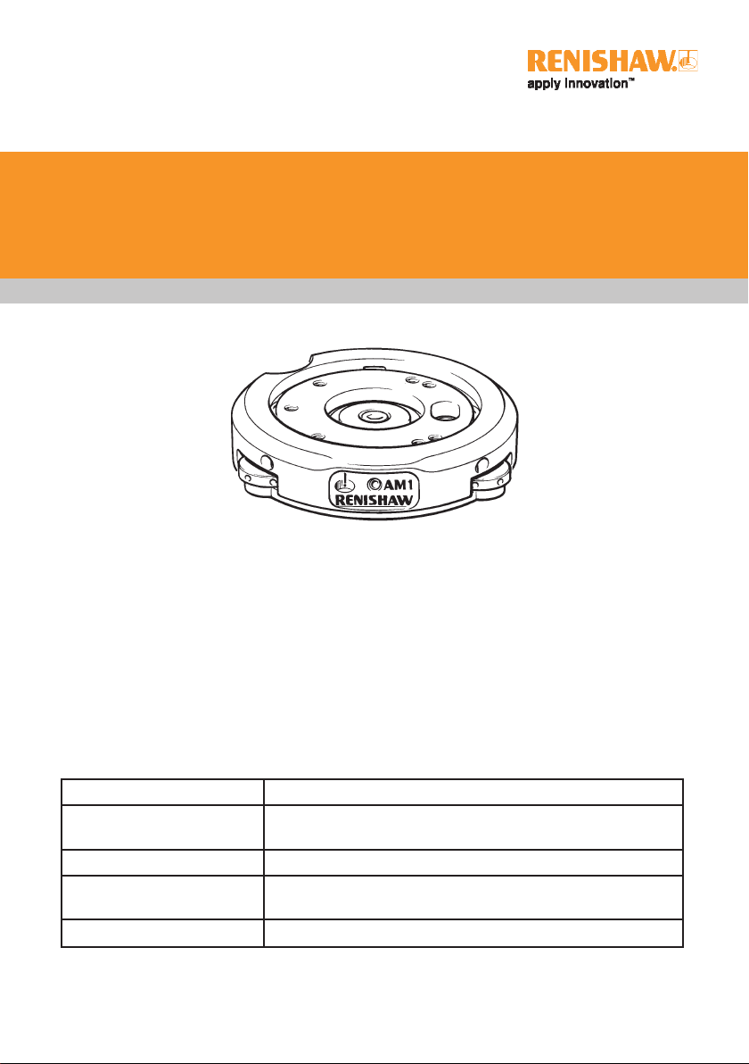
AM1 adjustment module
The AM1 adjustment module has been
designed for use with the PH6M and MIH
manual probe heads and the PH10T/M
motorised probe heads. It provides quick and
accurate angular alignment of the probe head
with the CMM’s axes and/or the autochange
rack.
In addition, the quick release mechanism
allows the head to be removed for storage and
subsequently replaced without re-alignment.
Built in overtravel protection decreases the risk
of head damage.
Specification
Size
Adjustment
Overtravel
Mounting
Weight
* Up to ±5.5° in pitch and roll is possible but this is at the expense of overtravel.
60 mm x 15.5 mm (2.36 in x 0.61 in) nominal
±2° in pitch and roll* (recommended)
±1.5° in yaw
±3.5° in pitch and roll
Mounts to quill using shank
Alternatively direct to quill using OEM adaptor
150 g (5.29 oz)
Page 2
1
AM1 adjustment module
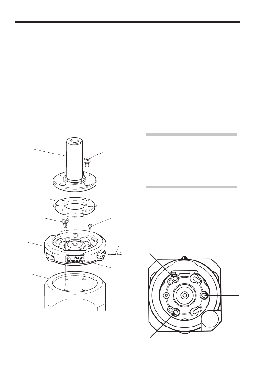
Installation
Follow these instructions carefully:
1 Preparation
Remove the safety screws (refer to
figures 1 and 4). Release the lock screw
in the front and the AM1. Unscrew and
retract ONE yaw adjusting screw. Rotate
mounting plate through 60° and remove.
Shank
Mounting plate
M3 x 6 mm
AM1
M3 x 5 mm
Safety
screw
Yaw
adjusting
screw
2 Locate AM1
Locate AM1 body to probe head and
secure with M3 x 6 mm screws. Use
three screws for PH10M and PH10T.
See figure 2 for top views of probe
heads and screw locations.
3 Refitting the mounting plate
Refit mounting plate to AM1 and locate
by rotating through 60°. Screw yaw
adjusting screw against lug.
NOTE: If shank / mounting plate
assembly is to be permanently attached
to the head, the safety screw should be
replaced before assembling the shank
on the mounting plate. Alternatively,
if quick release is required, the screw
should be left out.
4 Secure shank
Secure shank to mounting plate with four
M3 x 5 mm screws provided. Do not use
longer screws.
Probe
head
Figure 1 - AM1 installation
Lock
screw
Figure 2 - PH10M and PH10T
(three mounting screws)
Page 3

5 Roll adjustment
Rotate the roll adjustment capstans equally
and in opposite directions (i.e. one capstan
clockwise and the other anti-clockwise).
Refer to figures 4 and 5.
AM1 adjustment module
2
6 Pitch adjustment
Rotate the pitch adjustment capstan to
increase or decrease pitch. Refer to
figures 4 and 5.
7 Yaw adjustment
Release the lock screw. Rotate the yaw
adjusting screws equally in opposite
directions to provide required yaw. Tighten
the screws against each other without
applying excessive torque. Tighten the
lock screw. Refer to figures 4 and 5.
8 Quick release of AM1 from shank
NOTE: If repeatability of position is
required on re-attachment, DO NOT alter
the centre screw. This repeatability of
position is sufficient for alignment with
the autochange rack, but probes must be
redatumed for measurement.
Rotate AM1 until free and remove.
9 Re-attachment
Locate AM1 against the shank and rotate
until engaged. Tighten the yaw adjustment
screw. Tighten the lock screw.
Roll
adjustment
±2°
Pitch
Overtravel
±3.5°
Yaw
Figure 5 - Pitch, roll and yaw
Pitch adjusting capstan
Yaw adjusting screw
Roll adjusting capstans
Figure 4 - Angular adjustment (adjust the AM1 in the order given above)
Lock screw
Safety screw
Yaw adjusting screw
Roll adjusting capstans
Page 4

Renishaw plc
New Mills, Wotton-under-Edge,
Gloucestershire, GL12 8JR
United Kingdom
T +44 (0)1453 524524
F +44 (0)1453 524901
E uk@renishaw.com
www.renishaw.com
For worldwide contact details,
please visit our main website at
www.renishaw.com/contact
*H-1000-4010-03*
 Loading...