

Page 1
ACR3installationanduser'sguide
Document part number H-1000-5087-02-A
Page 1 of 45ACR3 installation and user's guide
10/12/2010file://C:\Temp\~hh63CD.htm
Page 2

Page 2 of 45ACR3 installation and user's guide
ACR3Careofequipment
Renishaw probes and associated systems are precision tools used for obtaining precise measurements
and must therefore be treated with care.
ChangestoRenishawproducts
Renishaw reserves the right to improve, change or modify its hardware or software without incurring any
obligations to make changes to Renishaw equipment previously sold.
Warranty
Renishaw plc warrants its equipment for a limited period (as set out in our Standard Terms and
Conditions of Sale) provided that it is installed exactly as defined in associated Renishaw documentation.
Prior consent must be obtained from Renishaw if non-Renishaw equipment (e.g. interfaces and/or
cabling) is to be used or substituted. Failure to comply with this will invalidate the Renishaw warranty.
Claims under warranty must be made from authorised Service Centres only, which may be advised by
the supplier or distributor.
Patents
Features of Renishaw’s ACR3 autochange rack system and associated equipment are the subjects of
the patents and patent applications listed below:
EP 0142373
EP 0293036
EP 0243766
EP 0388993
EP 0392660
EP 0392699
EP 0544854
EP 0501710
EP 0750171
EP 0826136
EP 242747 B
EP 548328 B
JP 2,098,080
JP 2,510,804
JP 2,545,082
JP 2,539,824
JP 2,994,422
10/12/2010file://C:\Temp\~hh63CD.htm
Page 3

JP 3,018,015
JP 3,101,322
JP 501,776/1994
JP 503,652/1994
JP 505,622/1999
US 4651405
US 4813151
US 4817362
US 5,084,981
US 5,088,337
US 5,339,535
US 5,323,540
US 5,345,689
Page 3 of 45ACR3 installation and user's guide
US 5,404,649
US 5,505,005
US 5,918,378
TW UM-099300
10/12/2010file://C:\Temp\~hh63CD.htm
Page 4

ACR3ECDECLARATIONOFCONFORMITY
ECDECLARATIONOFCONFORMITY
Renishaw plc declare that the product: -
Name: ACR3
Description: Autochange rack
Part no. A-5036-0005
Complies with directive:
2006/42/EC Machinery
Complies with standards
Page 4 of 45ACR3 installation and user's guide
BS EN 292-1:1991+ A1:2009 Safety of machinery - Basic concepts, general principles for design: -
BS EN 292-2:1991+ A1:2009 Part 1. Basic terminology, methodology.
Part 2. Technical principles and specifications.
The person authorised to compile the technical file and issue the declaration of conformity is:
Mark Acres
Compliance Manager
Renishaw plc, New Mills, Wotton-under-Edge,
Gloucestershire, GL12 8JR, United Kingdom
10/12/2010file://C:\Temp\~hh63CD.htm
Page 5

Page 5 of 45ACR3 installation and user's guide
ACR3warnings
EN
Pinch hazards exist between moving parts and between moving and static parts. Do not hold the probe
head during movements, or during manual probe changes.
In all applications involving the use of machine tools or CMMs, eye protection is recommended.
Beware of unexpected movement. The user should remain outside of the full working envelope of Probe
Head/Extension/Probe combinations.
Remove power before performing any maintenance operations.
For instructions regarding the safe cleaning of Renishaw products, refer to the Maintenance section of
the relevant product documentation.
It is the machine supplier’s responsibility to ensure that the user is made aware of any hazards involved
in operation, including those mentioned in Renishaw product documentation, and to ensure that
adequate guards and safety interlocks are provided.
FR
L’effet de pincement dû au mouvement des pièces mobiles entre elles ou avec des pièces fixes présente
des dangers. Ne pas tenir la tête du palpeur lorsqu’elle se déplace ou que le palpeur est changé à la
main.
Le port de lunettes de protection est recommandé pour toute application sur machine-outil et MMC.
Attention aux mouvements brusques. L'utilisateur doit toujours rester en dehors de la zone de sécurité
des installations multiples Tête de Palpeur/Rallonge/Palpeur.
Mettre la machine hors tension avant d'entreprendre toute opération de maintenance.
Les conseils de nettoyage en toute sécurité des produits Renishaw figurent dans la section
MAINTENANCE de votre documentation.
Il incombe au fournisseur de la machine d’assurer que l’utilisateur prenne connaissance des dangers
d’exploitation, y compris ceux décrits dans la documentation du produit Renishaw, et d’assurer que des
protections et verrouillages de sûreté adéquats soient prévus.
DE
Zwischen beweglichen und zwischen beweglichen und statischen Teilen besteht eine Einklemmgefahr.
Den Meßtasterkopf nicht anfassen, wenn er sich bewegt oder wenn ein manueller Meßtasterwechsel
durchgeführt wird. Bei der Bedienung von Werkzeugmaschinen oder Koordinatenmeßanlagen ist
Augenschutz empfohlen.
Auf unerwartete Bewegungen achten. Der Anwender sol sich immer außerhalb des Meßtasterkopf-Arm-
10/12/2010file://C:\Temp\~hh63CD.htm
Page 6

Page 6 of 45ACR3 installation and user's guide
Meßtaster-Bereichs aufhalten.
Bevor Wartungsarbeiten begonnen werden, muß erst die Stromversorgung getrennt werden.
Anleitungen über die sichere Reinigung von Renishaw-Produkten sind in Kapitel MAINTENANCE
(WARTUNG) in der Produktdokumentation enthalten.
Es obliegt dem Maschinenlieferanten, den Anwender über alle Gefahren, die sich aus dem Betrieb der
Ausrüstung, einschließlich der, die in der Renishaw Produktdokumentation erwähnt sind, zu unterrichten
und zu versichern, daß ausreichende Sicherheitsvorrichtungen und Verriegelungen eingebaut sind.
IT
Tra le parti in moto o tra le parti in moto e quelle ferme esiste effettivamente il pericolo di farsi del male
pizzicandorsi. Evitare di afferrare la testina della sonda quando è in moto, oppure quando si effettuano
spostamenti a mano.
Si raccomanda di indossare occhiali di protezione in applicazioni che comportano macchine utensili e
macchine per misurare a coordinate.
Fare attenzione ai movimenti inaspettati. Si raccomanda all'utente di tenersi al di fuori dell’involucro
operativo della testina della sonda, prolunghe e altre varianti della sonda.
Prima di effettuare qualsiasi intervento di manutenzione, isolare dall’alimentazione di rete.
Per le istruzioni relative alla pulizia dei prodotti Renishaw, fare riferimento alla sezione MAINTENANCE
(MANUTENZIONE) della documentazione del prodotto.
Il fornitore della macchina ha la responsabilità di avvertire l’utente dei pericoli inerenti al funzionamento
della stessa, compresi quelli riportati nelle istruzioni della Renishaw, e di mettere a disposizione i ripari di
sicurezza e gli interruttori di esclusione.
ES
Existe el peligro de atraparse los dedos entre las distintas partes móviles y entre partes móviles e
inmóviles. No sujetar la cabeza de la sonda mientras se mueve, ni durante los cambios manuales de la
sonda.
Se recomienda usar protección para los ojos en todas las aplicaciones que implican el uso de máquinas
herramientas y máquinas de medición de coordenadas.
Tener cuidado con los movimientos inesperados. El usuario debe quedarse fuera del grupo operativo
completo compuesto por la cabeza de sonda/extensión/sonda o cualquier combinación de las mismas.
Quitar la corriente antes de emprender cualquier operación de mantenimiento.
Para instrucciones sobre seguridad a la hora de limpiar los productos Renishaw, remitirse a la sección
titulada MAINTENANCE (MANTENIMIENTO) en la documentación sobre el producto.
Corresponde al proveedor de la máquina asegurar que el usuario esté consciente de cualquier peligro
que implica el manejo de la máquina, incluyendo los que se mencionan en la documentación sobre los
productos Renishaw y le corresponde también asegurarse de proporcionar dispositivos
10/12/2010file://C:\Temp\~hh63CD.htm
Page 7

Page 7 of 45ACR3 installation and user's guide
de protección y dispositivos de bloqueo de seguridad adecuados.
PT
Figo de constrição entre peças móveis e entre peças móveis e estáticas. Não segurar a cabeça da
sonda durante o movimento ou durante mudanças manuais de sonda.
Em todas as aplicações que envolvam a utilização de máquinas-ferramenta e CMMs, recomenda-se
usar protecção para os olhos.
Tomar cuidado com movimento inesperado. O utilizador deve permanecer fora do perímetro da área de
trabalho das combinações Cabeça da Sonda/ Extensão/ Sonda.
Desligar a alimentação antes de efectuar qualquer operação de manutenção.
Para instruções relativas à limpeza segura de produtos Renishaw, consultar a secção MAINTENANCE
(MANUTENÇÃO) da documentação do produto.
É responsabilidade do fornecedor da máquina assegurar que o utilizador é consciencializado de
quaisquer perigos envolvidos na operação, incluindo os mencionados na documentação do produto
Renishaw e assegurar que são fornecidos resguardos e interbloqueios de segurança adequados.
DA
Der er risiko for at blive klemt mellem bevægelige dele og mellem bevægelige og statiske dele. Hold ikke
sondehovedet under bevægelse eller under manuelle sondeskift.
I alle tilfælde, hvor der anvendes værktøjs- og koordinatmålemaskiner, anbefales det at bære
øjenbeskyttelse.
Pas på uventede bevægelser. Brugeren bør holde sig uden for hele
sondehovedets/forlængerens/sondens arbejdsområde.
Afbryd strømforsyningen, før der foretages vedligeholdelse.
Se afsnittet MAINTENANCE (VEDLIGEHOLDELSE) i produktdokumentationen for at få instruktioner til
sikker rengøring af Renishawprodukter.
Det er maskinleverandørens ansvar at sikre, at brugeren er bekendt med eventuelle risici i forbindelse
med driften, herunder de risici, som er nævnt i Renishaws produktdokumentation, og at sikre, at der er
tilstrækkelig afskærmning og sikkerhedsblokeringer.
NL
Er is risico op klemmen tussen de bewegende onderdelen onderling en tussen bewegende en nietbewegende onderdelen. De sondekop tijdens beweging of tijdens manuele sondeveranderingen niet
vasthouden.
Het dragen van oogbescherming wordt tijdens gebruik van machinewerktuigen en CMM’s aanbevolen.
Oppassen voor onverwachte beweging. De gebruiker dient buiten het werkende signaalveld van de
10/12/2010file://C:\Temp\~hh63CD.htm
Page 8

Page 8 of 45ACR3 installation and user's guide
Sondekop/Extensie/Sonde combinaties te blijven.
Voordat u enig onderhoud verricht dient u de stroom uit te schakelen.
Voor het veilig reinigen van Renishaw produkten wordt verwezen naar het hoofdstuk MAINTENANCE
(ONDERHOUD) in de produktendocumentatie.
De leverancier van de machine is ervoor verantwoordelijk dat de gebruiker op de hoogte wordt gesteld
van de risico’s die verbonden zijn aan bediening, waaronder de risico’s die vermeld worden in de
produktendocumentatie van Renishaw. De leverancier dient er tevens voor te zorgen dat de gebruiker is
voorzien van voldoende beveiligingen en veiligheidsgrendelinrichtingen.
SV
Risk för klämning existerar mellan rörliga delar och mellan rörliga och stillastående delar. Håll ej i
sondens huvud under rörelse eller under manuella sondbyten.
Ögonskydd rekommenderas för alla tillämpningar som involverar bruket av maskinverktyg och CMM.
Se upp för plötsliga rörelser. Användaren bör befinna sig utanför arbetsområdet för
sondhuvudet/förlängningen/sond-kombinationerna.
Koppla bort strömmen innan underhåll utförs.
För instruktioner angående säker rengöring av Renishaws produkter, se avsnittet MAINTENANCE
(UNDERHÅLL) i produktdokumentationen.
Maskinleverantören ansvarar för att användaren informeras om de risker som drift innebär, inklusive de
som nämns i Renishaws produktdokumentation, samt att tillräckligt goda skydd och säkerhetsförreglingar
tillhandahålls.
FI
Liikkuvien osien sekä liikkuvien ja staattisten osien välillä on olemassa puristusvaara. Älä pidä kiinni
anturin päästä sen liikkuessa tai vaihtaessasi anturia käsin.
Kaikkia työstökoneita ja koordinoituja mittauskoneita (CMM) käytettäessä suositamme silmäsuojuksia.
Varo äkillistä liikettä. Käyttäjän tulee pysytellä täysin anturin pään/jatkeen/anturin yhdistelmiä suojaavan
toimivan kotelon ulkopuolella.
Kytke pois sähköverkosta ennen huoltotoimenpiteitä.
Renishaw-tuotteiden turvalliset puhdistusohjeet löytyvät tuoteselosteen MAINTENANCE (HUOLTOA)
koskevasta osasta.
Koneen toimittaja on velvollinen selittämään käyttäjälle mahdolliset käyttöön liittyvät vaarat, mukaan
lukien Renishaw’n tuoteselosteessa mainitut vaarat. Toimittajan tulee myös varmistaa, että toimitus
sisältää riittävän määrän suojia ja lukkoja.
EL
10/12/2010file://C:\Temp\~hh63CD.htm
Page 9

Page 9 of 45ACR3 installation and user's guide
Υπάρχι κίνδυνος πιασίματος μεταξύ των κινούμενων μερών όπως και μεταξύ των κινούμενων και
στατικών μερών. Δεν πρέπει να κρατείτε την κεφαλή του ανιχνευτή κατά την κίνηση ούτε και κατά τη
διάπκεια χειροκίνητων αλλαγών του ανιχνευτή.
Σε όλες τις εφαρμογές που συνεπάγονται τη χρήση εργαλείων μηανημάτων και εξαρτημάτων CMM,
συνιστάται η χρήση συσκευής
Προσοχή – κίνδυνος απροσδόκητων κινήσεων. Οι χρήστες πρέπει να παραμένουν εκτός του χώρου που
επηρεάζεται από όλους τους συνδυασμούς λειτουρμίας της κεφαλής τοθ ανιχνευτή, της προέκτασης και
του ανιχνευτή.
Αποσυνδέστε το μηχάνημα από το ηλεκτρπικό ρεύμα προτού επιχειρήσετ τυχόν εργασίες.
προστασίας των ματιών.
Για οδηγίες που αφορούν τον ασφαλή καθαρισμό των
MAINTENANCE (ΣΥΝΤΗΡΗΣΗ) στο διαφωτιστικό υλικ του προϊόντος.
προϊόντων Renishaw βλέπετε το κεφάλαιο
10/12/2010file://C:\Temp\~hh63CD.htm
Page 10
Page 10 of 45ACR3 installation and user's guide
ACR3introduction
This guide contains information relating to the installation and operation of Renishaw’s ACR3
(autochange rack) system.
This guide takes a step by step approach to fitting, aligning and datuming the rack as well as providing
operational and troubleshooting guidance.
System integration and software routines recommended for the successful implementation of the ACR3
are also provided.
10/12/2010file://C:\Temp\~hh63CD.htm
Page 11
Page 11 of 45ACR3 installation and user's guide
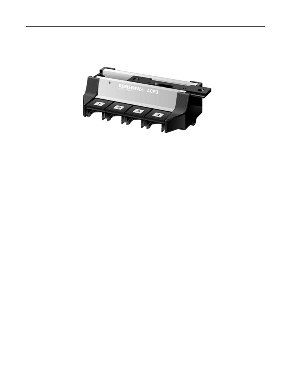
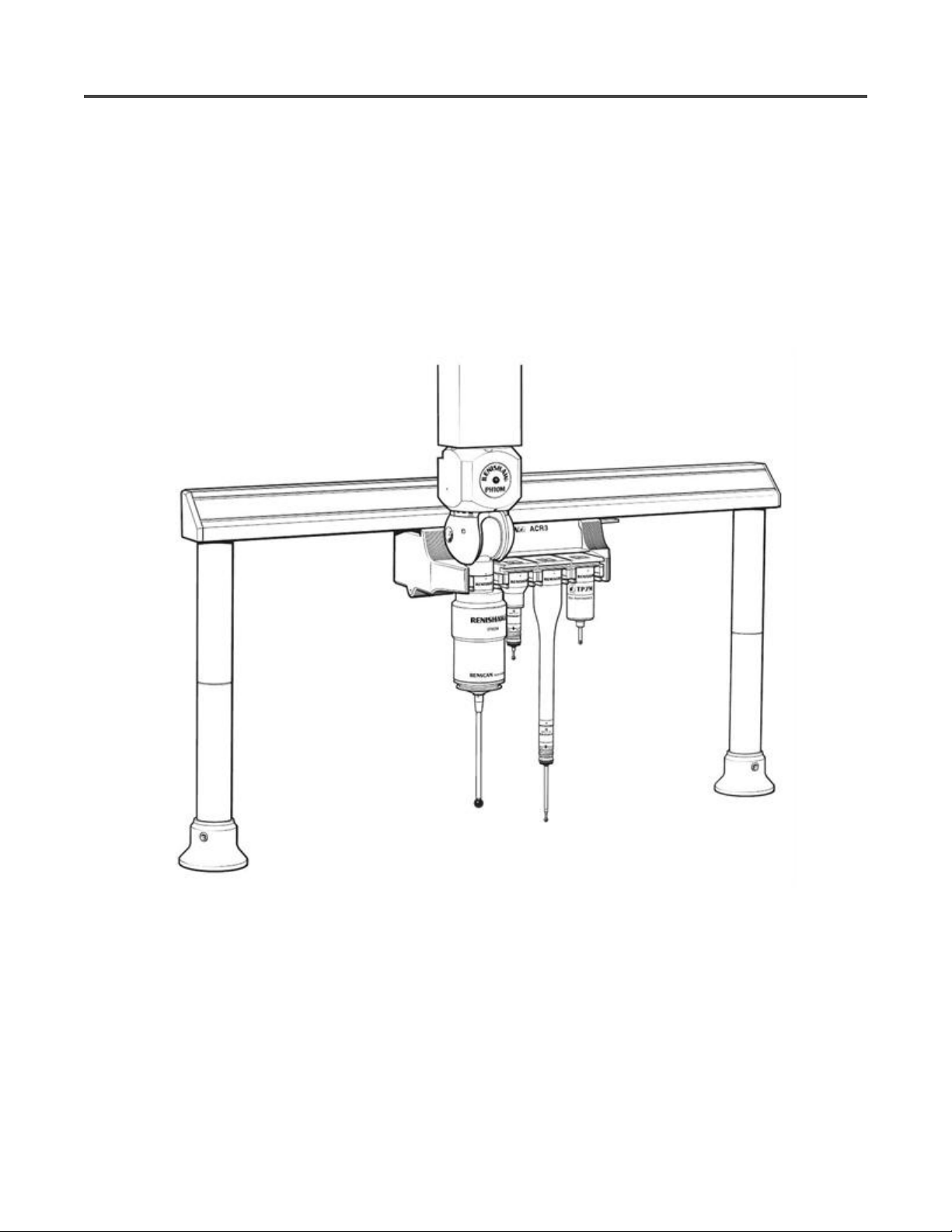
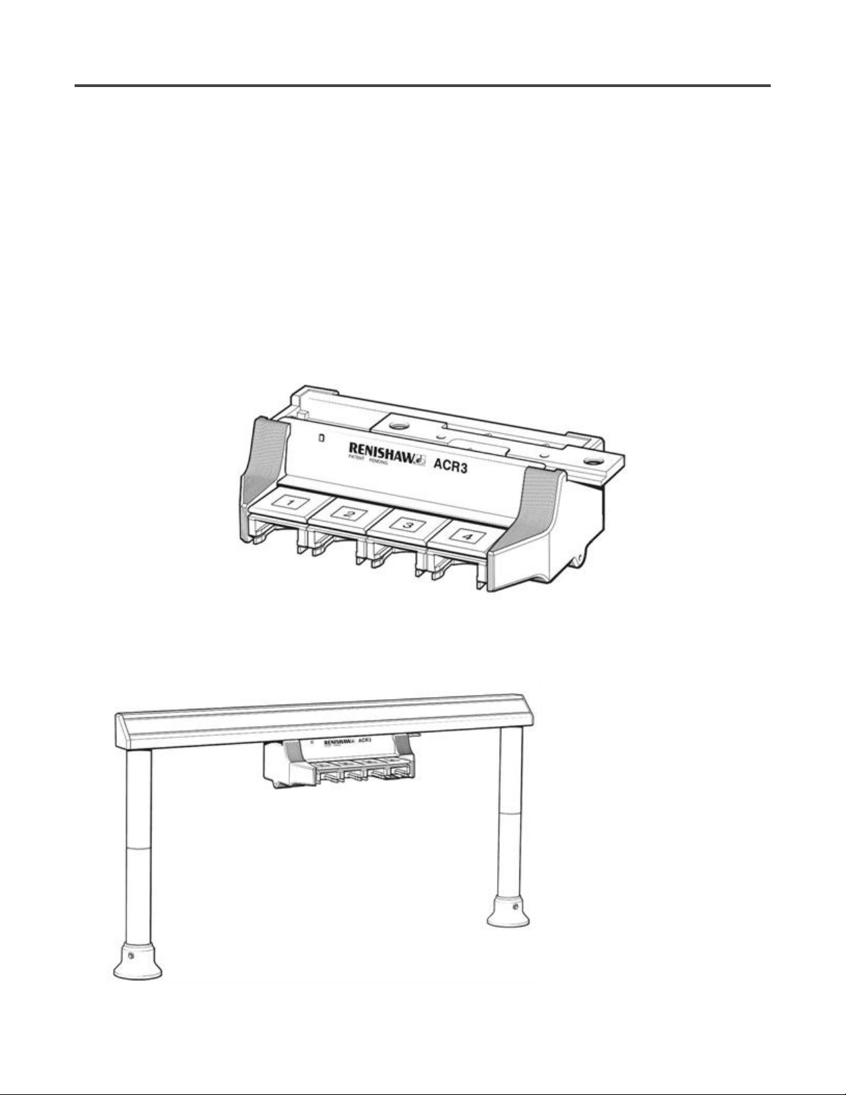
ACR3systemdescription
Renishaw’s ACR3 is a four port rack that facilitates fast, automatic probe exchange without the need for
probe re-qualification. The ACR3 is a four port mechanical design that traverses the MRS rail. Driven by
the motion of the CMM, it locks and unlocks the autojoint between the probe and the probe head. In
addition, the ACR3 provides covered storage and protection for up to eight probes and extension bars
(two four port systems can be linked to provide an eight port system).
Mounted within the CMM’s working envelope, the ACR3 is combined with the modular rack system
(MRS) to form an automatic change rack for probes and extension bars that incorporate the Renishaw
autojoint. Each rack port is of modular design to permit easy replacement should wear occur during the
operational life of the ACR3.
Fast probe exchange cycles are achieved by the probe head docking the original probe and selecting a
new one. The autochange system consists of a four port autochange rack (ACR3) and the modular rack
system (MRS) as shown below.
10/12/2010file://C:\Temp\~hh63CD.htm
Page 12
Page 12 of 45ACR3 installation and user's guide
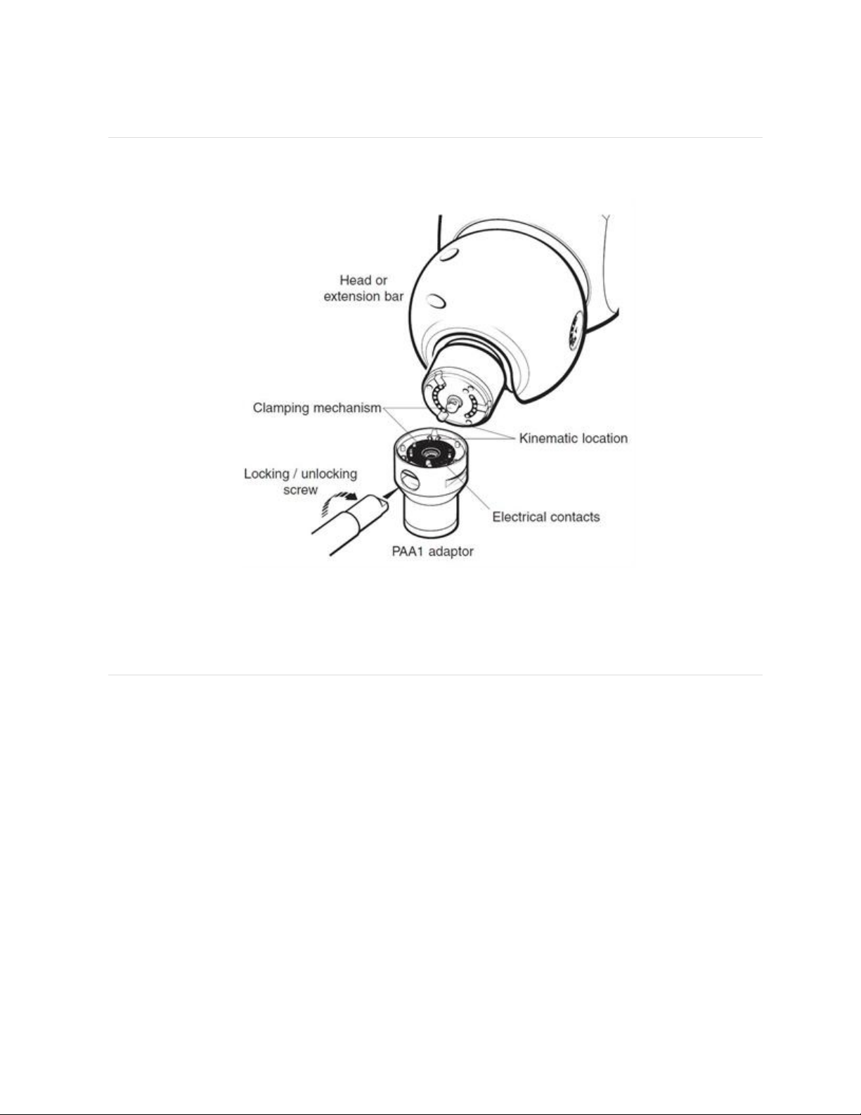
Autojoint
The autojoint (shown below) is a highly repeatable kinematic joint, one half of which is attached to the
probe head, the other half to a probe, extension bar or adapter.
Locking and unlocking of the autojoint is achieved either manually, using an autojoint key, or
automatically, using the autochange rack system. In all cases, the repeatability of the autojoint eliminates
the need for probe requalification after each probe exchange.
MRS
The MRS is the common mounting platform for the ACR3, SCP600 (stylus change port for SP600) and
FCR25 (flexible change rack for SP25M). It is available in a number of different overall lengths and
heights. For a detailed explanation of this system, please refer to the MRS installation and user’s guide
(part no. H-1000-5088).
10/12/2010file://C:\Temp\~hh63CD.htm
Page 13
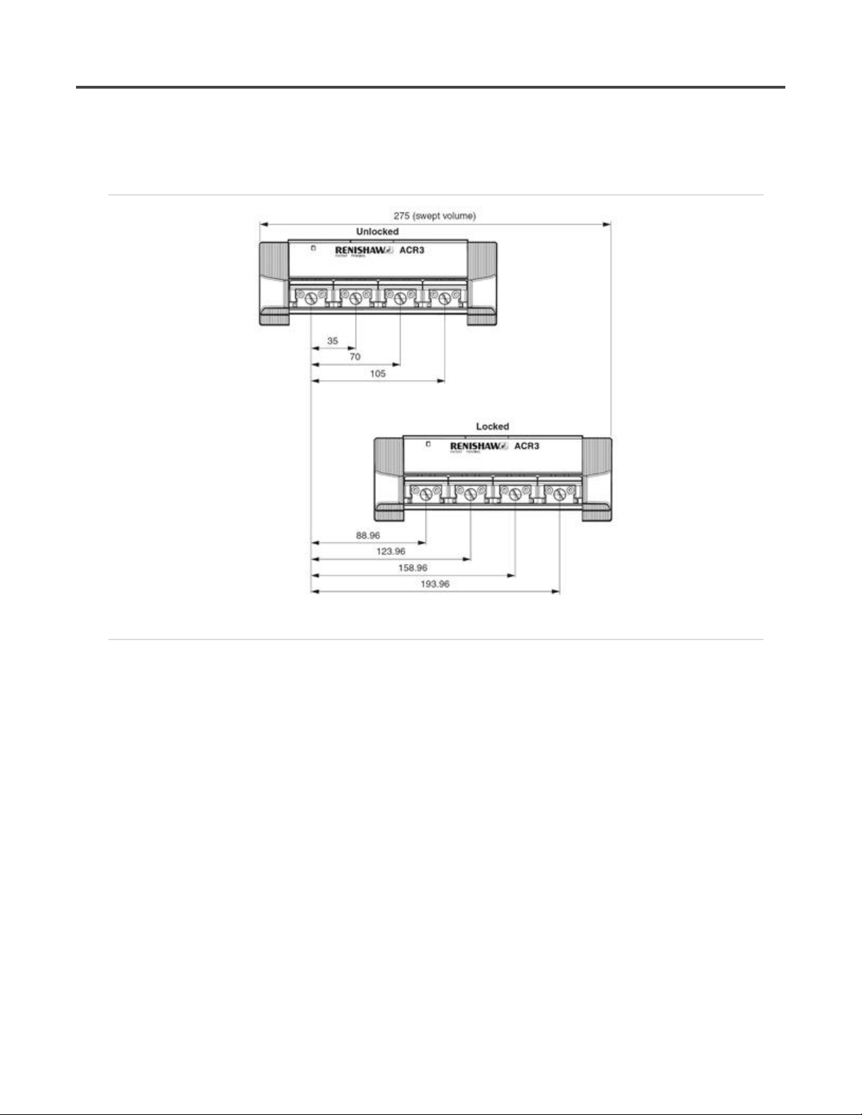
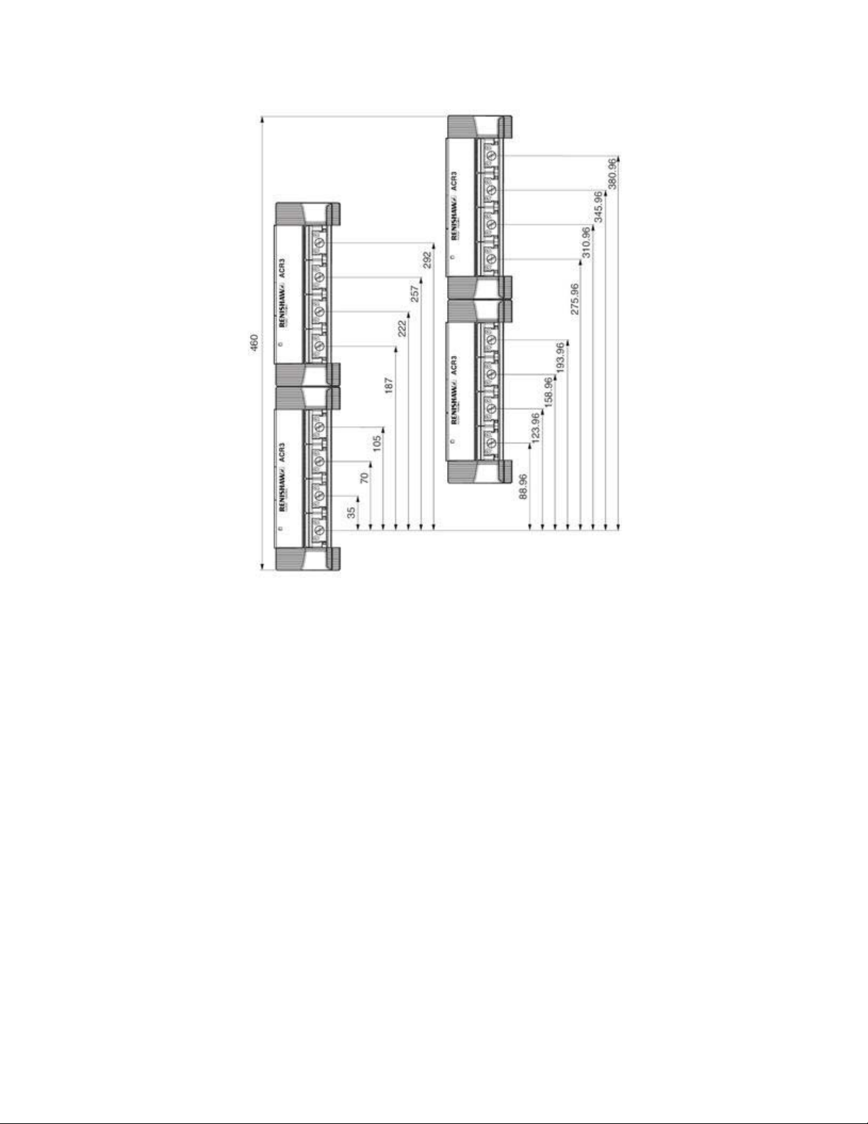
ACR3systemdimensions
4portACR3systemdimensions
Page 13 of 45ACR3 installation and user's guide
8portACR3systemdimensions
10/12/2010file://C:\Temp\~hh63CD.htm
Page 14
Page 14 of 45ACR3 installation and user's guide
10/12/2010file://C:\Temp\~hh63CD.htm
Page 15

Page 15 of 45ACR3 installation and user's guide
CompatibleRenishawproducts
Renishaw have a number of probe heads and probes that have either the male or female part of the
autojoint fitted to them and are therefore compatible for use with the ACR3. For additional information,
please refer to the relevant product documentation.
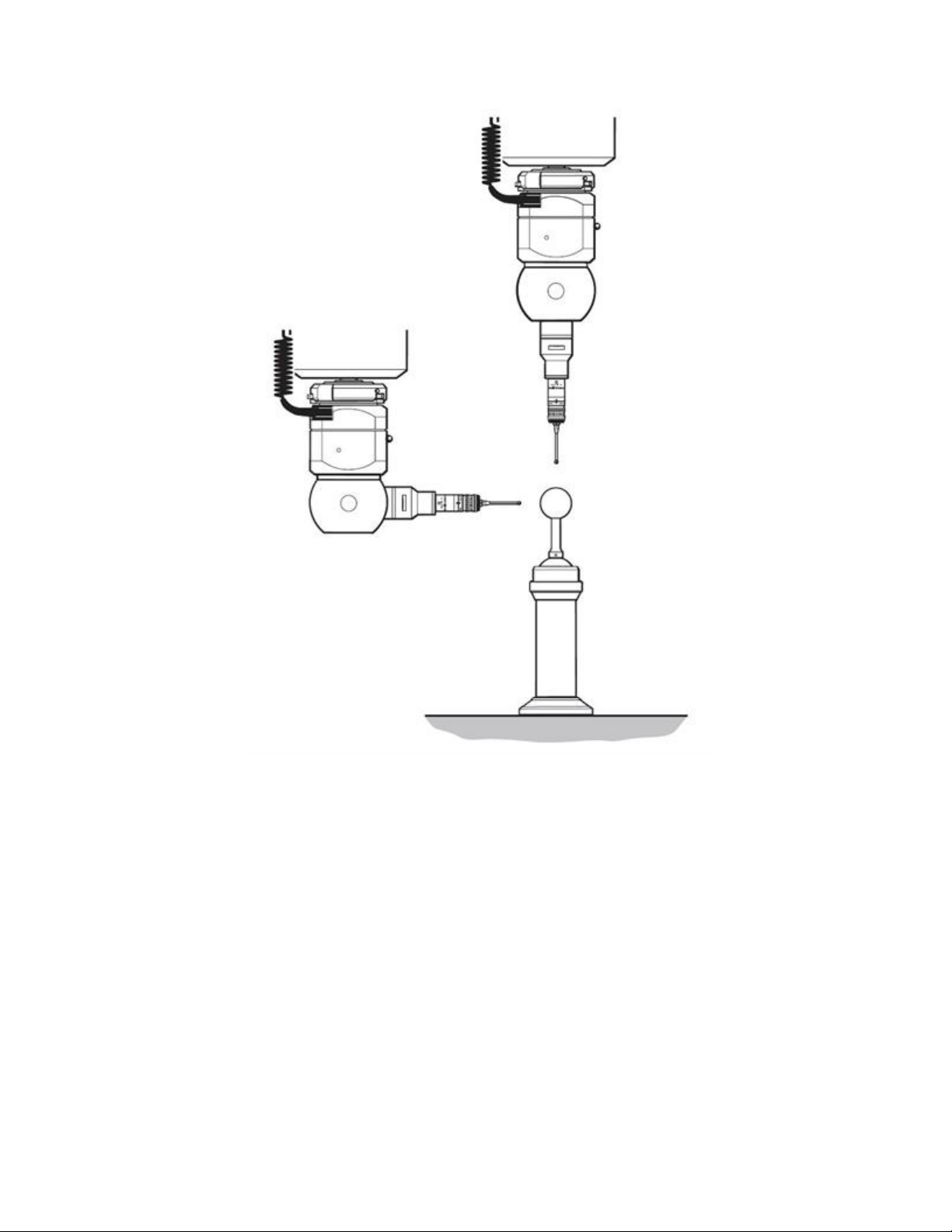
Heads
PH10M – A motorised indexing probe head with 720 repeatable positions suitable for all two wire and
multiwired probes.
PH10MQ – This is an in-quill mounted version of the PH10M head.
PH6M – A fixed autojointed probe head suitable for all two wire and multiwired probes.
Probes
SP25 – High accuracy scanning probe enabling the user to scan for form measurement and reverse
engineering, rapid TTP for geometric measurements is also possible.
SP600M – Analogue contact scanning probe which is ideal for profile scanning and it features 300 mm
stylus capability. Permits the CMM to gather large amounts of data very rapidly.
TP7M – High accuracy strain gauge based touch-trigger probe.
TP6A – This is a probe suited to general purpose probing applications offering longer and heavier styli
carrying capability.
OTP6M – An optical trigger probe that uses a visible laser spot to provide a non-contact inspection
solution for CMMs.
Using the Renishaw range of probe adaptor bars (PAA), the complete range of Renishaw M8 probes can
be used in conjunction with the autochange system; a brief description of some of these probes is given
below:
TP20 – A 13 mm diameter kinematic touch-trigger probe consisting of a two piece design that provides
the facility to repeatedly change probe modules without the need for re-qualification.
TP200 – A 13 mm diameter strain gauge based touch-trigger probe consisting of a two piece design that
provides the facility to repeatedly change stylus modules without the need for re-qualification.
TP2 - A 13 mm diameter kinematic touch-trigger probe with adjustable stylus force.
TP6 – A 25 mm diameter kinematic touch-trigger probe of a robust design.
NOTE 1: ACR3 can only be used in the horizonal orientation.
NOTE 2: It is not possible to remove probes off the end of extension bars using ACR3.
10/12/2010file://C:\Temp\~hh63CD.htm
Page 16

Page 16 of 45ACR3 installation and user's guide
HeadalignmentforACR3
It is necessary for the probe head to be aligned with both the movements of the CMM and the ACR3.
This is because the autojoint is a high force mechanical joint that could cause operational errors if used
with an incorrectly aligned ACR3.
NOTE: The Renishaw PH10 motorised head system has been designed so that the roll and pitch of
the autojoint is held within the tolerances required for the ACR3 system, when connected to a
standard Renishaw shank.
In the majority of installations only the yaw of the motorised head requires alignment. However, it is
possible that the location of the probe head shank to the CMM quill, or the mounting face of the PH10MQ
to the CMM quill, is not held to the required tolerances. In some cases, this could result in excessive
ACR3 port wear or failure of the ACR3 to change probes.
This problem can be rectified by using either the AM1 or AM2 adjustment module.
Alignmentofthehead‐roll
The roll axis of the head is from the left-hand side to the right-hand side of the probe head. The
maximum recommended alignment error is 0.2°.
The recommended procedure for setting the roll of a motorised or indexing probe head is as follows (see
figure 7):
NOTE: During this procedure the probe should not be qualified.
1. Index the probe head to an A axis position of 90° and a B axis position of -90°.
2. Using the probe attached to the probe head, measure the qualification sphere on the CMM table
(sphere 1). Use the centre of this measured sphere as a datum.
3. Index the probe head to an A axis position of 90° and a B axis position of 90°.
4. Using the probe attached to the probe head, measure the qualification sphere on the CMM table
(sphere 2).
5. Calculate the roll angle for the probe head using the following formula:
arc TAN {Z axis position of sphere 2 / Y axis position of sphere 2} = Roll angle
(recommended <0.2°)
6. If the roll angle exceeds 0.2° then adjustment is required, please refer to ‘
‘
Adjusting the AM2’ as appropriate and repeat steps 1 to 5.
Adjusting the AM1’ or
10/12/2010file://C:\Temp\~hh63CD.htm
Page 17

Page 17 of 45ACR3 installation and user's guide
Alignmentofthehead‐pitch
The pitch axis of the head is from the front of the probe head (where the LED is located) to the rear of the
probe head. The maximum recommended alignment error is 0.2°.
The recommended procedure for setting the pitch of a motorised or indexing probe head is as follows
(see figure 8):
NOTE: During this procedure the probe should not be qualified.
1. Index the probe head to an A axis position of 90° and a B axis position of 0°.
2. Using the probe attached to the probe head, measure the qualification sphere on the CMM table
(sphere 1). Use the centre of this measured sphere as a datum.
3. Index the probe head to an A axis position of 90° and a B axis position of 180°.
4. Using the probe attached to the probe head, measure the qualification sphere on the CMM table
(sphere 2).
5. Calculate the pitch angle for the probe head using the following formula:
arc TAN { Z axis position of sphere 2 / X axis position of sphere 2 } = Pitch angle
(recommended <0.2°)
6. If the roll angle exceeds 0.2° then adjustment is required, please refer to ‘
‘Adjusting the AM2’as appropriate and repeat steps 1 to 5.
Adjusting the AM1’ or
10/12/2010file://C:\Temp\~hh63CD.htm
Page 18

Page 18 of 45ACR3 installation and user's guide
Alignmentofthehead‐yaw
The yaw axis of the head is the rotational axis of the probe head with respect to the quill of the CMM.
The maximum recommended alignment error is 0.2°.
The recommended procedure for setting the yaw of a motorised or indexing head is as follows:
NOTE: During the procedure the probe should not be qualified.
1. Index the probe head to an A axis position of 0° and a B axis position required for an autojoint probe to
enter the ACR3.
2. Using the probe attached to the probe head, measure the qualification sphere on the CMM table
(sphere 1). Use the centre of the measured sphere as a datum.
3. Index the probe head to an A axis position of 90°, maintaining the same B axis position as in step 1.
4. Using the probe attached to the probe head, measure the qualification sphere on the CMM table
(sphere 2).
5. Calculate the yaw angle of the probe head using the following formula:
arc TAN { X axis position of sphere 2 / Y axis position of sphere 2 } = Yaw angle
(recommended <0.2°)
6. If the yaw angle exceeds 0.2° then adjustment is required, please refer to ‘
‘Adjusting the AM2’ as appropriate and repeat steps 1 to 5.
Adjusting the AM1’ or
10/12/2010file://C:\Temp\~hh63CD.htm
Page 19
Page 19 of 45ACR3 installation and user's guide
10/12/2010file://C:\Temp\~hh63CD.htm
Page 20

Page 20 of 45ACR3 installation and user's guide
AM1adjustablemodule
The AM1 adjustment module is designed to provide quick and accurate angular alignment of the PH6M
and PH10M with the axes of the CMM and Renishaw ACR3.
In addition, the quick release mechanism allows the probe heads to be removed for storage and replaced
without further alignment. In-built overtravel protection minimises the risk of probe head damage.
AdjustingtheAM1
Below are instructions on how to adjust the AM1 in order to align the probe head to the CMM axes. The
procedure should be carried out in the order specified:
1. Roll adjustment - rotate the roll adjusting capstans equally and in opposite directions (i.e. rotate one
capstan clockwise and the other anti-clockwise) to adjust roll.
2. Pitch adjustment - rotate the pitch adjusting capstan to increase or decrease the pitch.
3. Yaw adjustment -
1. Release the lock screw.
2. Rotate the yaw adjusting screws equally in opposite directions to provide the required yaw.
3. Tighten the screws against each other without applying excessive torque.
4. Tighten the lock screw
4. Quick release of the AM1 from shank -
1. Release the lock screw.
2. Retract ONE yaw adjustment screw.
NOTE: If repeatability of position is required on re-attachment, DO NOT alter the other screw. This
repeatability of position is normally sufficient for alignment with the autochange rack, but probes
10/12/2010file://C:\Temp\~hh63CD.htm
Page 21

must be re-qualified for measurement.
5. Re-attachment of AM1 to shank -
1. Locate the AM1 against the shank and rotate until engaged.
2. Tighten the yaw adjustment screw.
3. Tighten the locking screw.
Page 21 of 45ACR3 installation and user's guide
10/12/2010file://C:\Temp\~hh63CD.htm
Page 22
Page 22 of 45ACR3 installation and user's guide
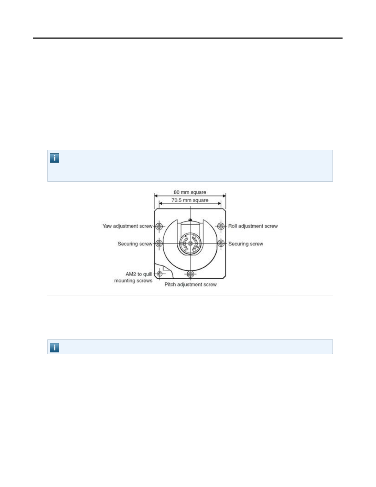
AM2adjustmentmodule
The AM2 adjustment module is designed to provide quick and accurate angular alignment of the
PH10MQ motorised probe head with the axes of the CMM and Renishaw ACR3.
The AM2 consists of the adjuster plate, which is attached to the quill of the CMM, and a set of adjusters
fitted to the flange of the head.
The probe head is fixed to the adjuster plate by a pair of captive screws.
The AM2 incorporates a quick release mechanism that allows the same probe head to be removed for
storage and refitted without further alignment.
NOTE: If repeatability of position is required on re-attachment, only the securing screws should be
released. Do not alter the other screws. This repeatability of position is normally sufficient for
alignment with the autochange rack, but probes must be requalified for measurement.
AdjustingtheAM2
A special tool is supplied, consisting of a concentric hexagon key and socket spanner. This should be
located on the adjusters and locknuts recessed into the face of the head mounting flange.
NOTE: Springs are fitted under the adjuster locknuts to provide some preload during set up.
The procedure to use this tool is:
1. Slacken the locknut slightly using the outer part of the tool.
2. Set the adjuster using the inner part of the tool.
3. While holding the adjuster stationary with the inner part of the tool, tighten the locknut using the
outer part of the tool:
4.
4.
Roll adjustment: Using the AM2 tool and the procedure given above, adjust the roll
adjustment screw on the AM2.
10/12/2010file://C:\Temp\~hh63CD.htm
Page 23

Page 23 of 45ACR3 installation and user's guide
Pitch adjustment: Using the AM2 tool and the procedure given above, adjust the pitch
adjustment screw on the AM2.
Yaw adjustment: Using the AM2 tool and the procedure given above, adjust the yaw
adjustment screw on the AM2.
5. Tighten the two securing screws.
NOTE: Tightening the securing screws could cause the roll, pitch or yaw alignment to change. It is
therefore recommended that the alignments
are checked after this procedure.
10/12/2010file://C:\Temp\~hh63CD.htm
Page 24
Page 24 of 45ACR3 installation and user's guide
FittingafourportACR3systemtoMRS
It is recommended that the ACR3 rack be attached to the MRS rack using the following procedure.
During this procedure, it is assumed that the MRS rack has been installed as detailed in the MRS
installation guide (H-1000-5088).
CAUTION: Moving parts, beware of pinch hazards. The MRS must be securely bolted to the
machine table.
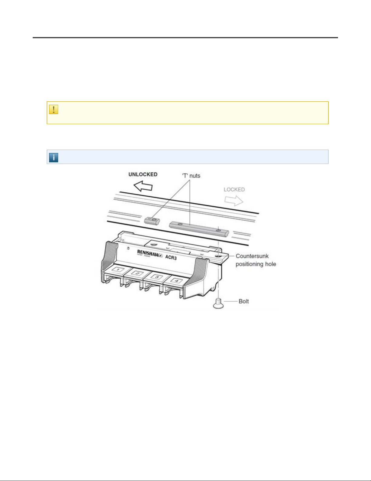
1. With the ARC3 in fully unlocked position; place bolt through the righthand countersunk clearance
hole, into thread of the long 'T' nut and finger tighten.
NOTE: Ensure T-nuts are positioned as indicated below.
2. With the ACR3 in fully locked position; place bolt through the left-hand countersunk clearance hole,
into the thread of the short 'T' nut and finger tighten.
10/12/2010file://C:\Temp\~hh63CD.htm
Page 25
Page 25 of 45ACR3 installation and user's guide
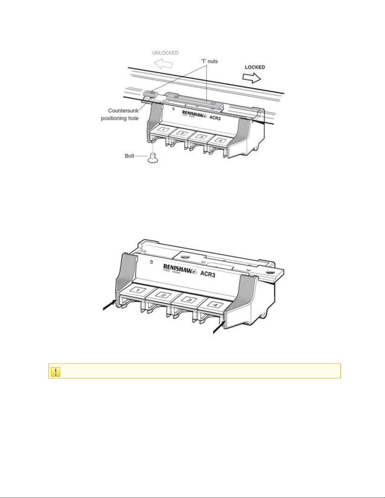
3. Position the ACR3 on the MRS rack such that the rack can move freely from its unlocked position to its
locked position.
4. Using the 5 mm hex key (supplied), tighten the two countersunk bolts.
5. Check the alignment of the ACR3 with respect to the CMM axis. This is achieved by taking two points
on the front of the ACR3 as shown below. The ‘run out’ of the ACR3, with respect to the CMM axis,
should be less than 0.5 mm between these two points.
6. Adjustment of the ACR3 (with respect to the machine axis) should be completed by releasing the
appropriate countersunk bolt and manually re-positioning the ACR3 and then re-tightening the bolt.
CAUTION: Ensure rack does not overhang the MRS in either the locked or unlocked position.
10/12/2010file://C:\Temp\~hh63CD.htm
Page 26

NOTE: The springs supplied can be inserted into the short 'T' nut and used to maintain the position
of the 'T' nut in the MRS rail.
Page 26 of 45ACR3 installation and user's guide
10/12/2010file://C:\Temp\~hh63CD.htm
Page 27

FittinganeightportACR3systemtoMRS
The long 'T' nut is designed to allow two 4 port units to be linked, as shown below.
Page 27 of 45ACR3 installation and user's guide
The distance required between the two racks is ‘set’ by the 'T' nut.
CAUTION: Moving parts, beware of pinch hazards. The MRS must be securely bolted to the
machine table.
1. Mount ACR3 ports 1-4 as detailed in "Fitting a four port ACR3 system to MRS"
long 'T' nut is positioned as indicated above.
2. Slide ACR3 to the fully unlocked position (left-hand side of travel). Push ACR3 ports 5 - 8 into the fully
locked position (right-hand side of travel). Pass the bolt through the left hand countersunk clearance hole
into the long T nut. Finger tighten.
NOTE: The long 'T' nut must be used when linking two ACR3s.
CAUTION: Ensure rack does not overhang the MRS in either the locked or unlocked position.
3. Push the ACR3 ports 5 - 8 into the fully unlocked position to the left. Place bolt through the right-hand
countersunk clearance hole into short 'T' nut and finger tighten, as in figure 17.
. However, ensure the
10/12/2010file://C:\Temp\~hh63CD.htm
Page 28

Page 28 of 45ACR3 installation and user's guide
4. Position the ACR3 on the MRS so that the rack can move freely from its unlocked position to its locked
position.
5. Using the 5 mm hex key (supplied), tighten the four countersunk bolts.
6. Using the connection bolt and O-ring supplied with the ACR3 kit, join the two ACR3 units as shown
below. Use the O-ring supplied to separate the two racks.
7. Check the alignment of each of the ACR3’s with respect to the CMM axis. This is achieved by taking
two points on the front of each ACR3 unit as shown in figure 14. The ‘run out’ of each of the ACR3 units,
with respect to the CMM axis, should be less than 0.5 mm, between the points on each rack.
10/12/2010file://C:\Temp\~hh63CD.htm
Page 29

Page 29 of 45ACR3 installation and user's guide
8. Adjustment of the ACR3’s (with respect to the machine axis) should be completed by releasing the
necessary mounting bolt, manually repositioning the ACR3 and then re-tightening the bolt.
10/12/2010file://C:\Temp\~hh63CD.htm
Page 30

Page 30 of 45ACR3 installation and user's guide
DatumingtheACR3
The following section describes the recommended procedure for datuming the ACR3 once it is fitted to
the MRS rack and the MRS is fitted to the CMM table (please refer to 'Fitting the ACR3 to the MRS - 4
port and 8 port').
Each rack comes with a setting gauge (see below) that is designed to assist in the datuming of the
ACR3.
LocatingtheZposition
1. Position the ACR3 so that it is in the unlocked position (positioned to the left-hand side of the travel).
2. Insert the lid clips as shown below.
NOTE: This procedure assumes the rack is aligned with the Y axis. If the rack is aligned with the X
axis, transpose X and Y.
3. Position the ACR3 setting gauge into port 1 as shown.
10/12/2010file://C:\Temp\~hh63CD.htm
Page 31

4. Inhibit the probe signal. It is recommended that this is done from within the CMM software.
Use extreme caution: The machine could be crashed.
Page 31 of 45ACR3 installation and user's guide
5. Remove the probe from the probe head (at the autojoint).
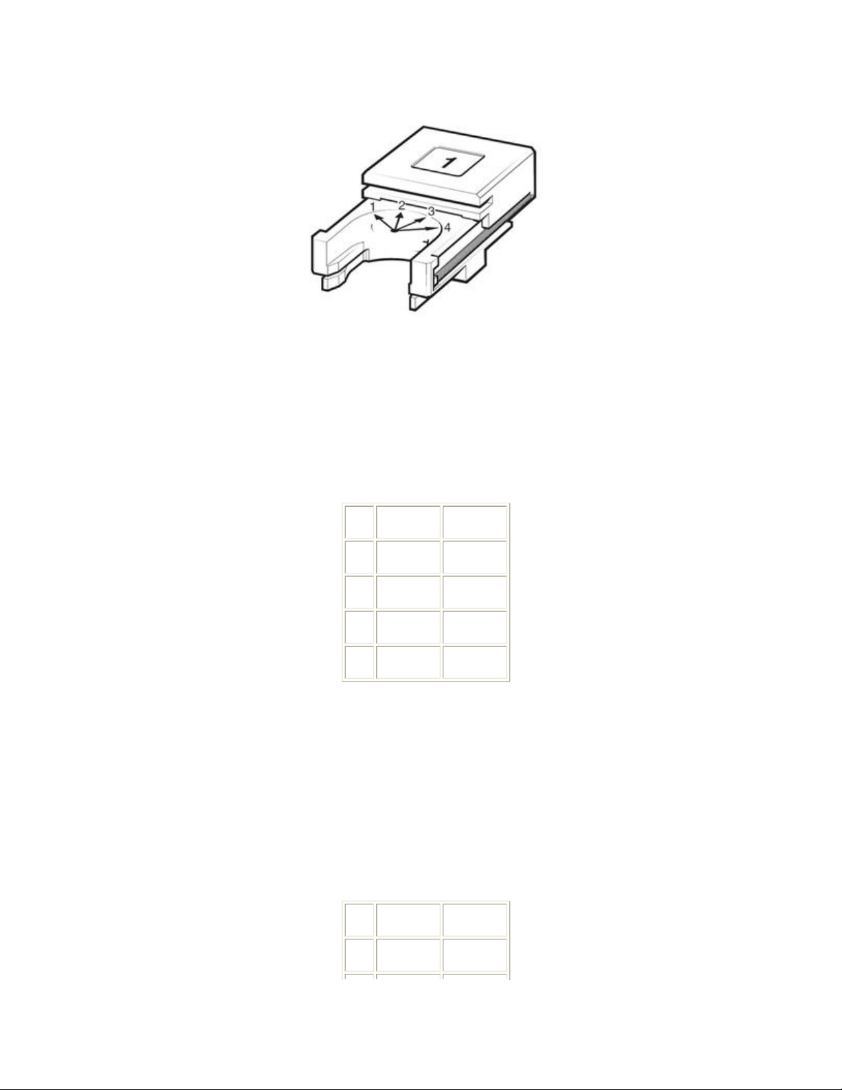
6. Position the autojoint puller into the central slot of the ACR3 setting piece. Take care not to move the
position of the ACR3 (see figure 21).
7. Using ~50 μm DCC incremental moves, slowly lower the autojoint face so that it just touches (machine
Z axis) onto the top face of the setting gauge. Use it as a feeler gauge to identify the correct Z axis
position for the probe head with respect to the ACR3. Record a point at this position (point A).
NOTE: More than one attempt may be required to get a ‘feel’ for this operation.
LIVE CMM AXES: REMAIN OUTSIDE WORKING ZONE BETWEEN Z POSITION CHECKS. DO
NOT ALLOW OTHERS TO OPERATE THE CMM DURING THIS PROCESS.
8. Remove the probe head from the ACR3 setting piece.
It is not possible to use the probe to find the ‘Z’ position because of tolerance stackups within the
probe and stylus combination.
10/12/2010file://C:\Temp\~hh63CD.htm
Page 32

Page 32 of 45ACR3 installation and user's guide
LocatingtheXposition
1. Move the probe head so that the external surface of the autojoint is just touching the front of the
ACR3 setting piece. Use ~50 μm DCC incremental moves, to identify the correct Y axis position.
2. Record a point at this position (point B).
3. Move the probe head clear of the ACR3 and connect the probe assembly.
NOTE: Ensure that the autojoint locking cam is positioned approximately 5° backed off from the
fully locked position and enable the probe signal.
4. Remove the ACR3 setting piece from port 1.
LocatingtheYposition
1. Manually take 4 points on the top of port 1 (port1 unlocked, points 1 to 4) as shown below, to create a
plane.
NOTE: Take care not to take a point to close to the lid clip as this may cause a problem later on in
the datuming procedure.
2. Manually take 4 points round the curved part at the rear of port 1 (port1 unlocked, circle centre) as
10/12/2010file://C:\Temp\~hh63CD.htm
Page 33
shown in figure 24. Take care to avoid the driver blade and the mounting screw holes.
3. Construct an axis system using:
“Port1 unlocked, points 1 to 4” as the primary plane (refer to step 1).
“Port1 unlocked, circle centre” as the secondary axis and tertiary axis origin (refer to step 2).
Store this axis system as (axis 1).
Page 33 of 45ACR3 installation and user's guide
4. The CMM can now locate ports 2 to 4 in the unlocked position under CNC control. The table below
shows the nominal location of the centre of these ports, assuming that the rack is running along the
CMM’s Y axis.
Port X position Y position
1 0 0
2 0 35
3 0 70
4 0 105
Dimensions in mm
The recommended procedure for locating the ports is as follows (see steps 1 and 2 for reference):
Move stylus to nominal XY centre of port.
Move stylus to 2 mm below the top surface of the port, in the current axis (axis 1) system.
Take 4 points round the curved part at the rear of the port.
Use the 4 points to create a circle, use this as a sub-datum in the XY axis.
Take 4 points on the top surface of the port.
Port X position Y position
1 8 -13.5
10/12/2010file://C:\Temp\~hh63CD.htm
Page 34

Page 34 of 45ACR3 installation and user's guide
2 -8 -13.5
3 -8 13.5
4 8 13.5
Dimensions in mm
Store the points as port* unlocked points 1 to 4.
Store the circle as port* unlocked circle 1.
Recall axis 1 (see step 3).
Locate the next port.
* Port number (e.g. 1, 2, 3 etc.).
6. If an eight port ACR3 is to be fitted to the CMM then step 7 should be completed, otherwise please go
to step 8.
7. The CMM can now locate ports 5 to 8 in the unlocked position under CNC control. The table below
shows the nominal location of the centre of these ports, with respect to the axis 1, assuming that the rack
is running along the CMM’s Y axis.
Port X position Y position
5 0 187
6 0 222
7 0 257
8 0 292
Dimensions in mm
The recommended procedure for locating 5 to 8 ports is as follows (see steps 1 and 2 for reference):
Take a Z axis reference point (x = 6.5 mm, y = 173.8 mm) for ACR3 in the unlocked position. Use this
point as a Z axis sub datum for locating ports 5 through 8 in the unlocked position.
Move stylus to nominal XY centre of port.
Move stylus to 2 mm below the top surface of the port, in the current axis (axis 1) system.
Take 4 points round the curved part at the rear of the port.
Use the 4 points to create a circle, use this as a sub-datum in the XY axis.
Take 4 points on the top surface of the port.
10/12/2010file://C:\Temp\~hh63CD.htm
Page 35

Port X position Y position
1 8 -13.5
2 -8 -13.5
3 -8 13.5
4 8 13.5
Dimensions in mm
Store the points as port* unlocked points 1 to 4.
Store the circle as port* unlocked circle 1.
Recall axis 1. (see step 3).
Locate the next port.
Page 35 of 45ACR3 installation and user's guide
* Port number (e.g. 5, 6, 7 etc.).
8. Move the probe head clear of the ACR3.
9. Move the ACR3 to the locked position (positioned to the right-hand side of the travel).
10. Take a Z axis reference point (x = 6.5 mm, y = 75.5 mm) for ACR3 position in the locked position.
Use this point as a Z axis sub datum for locating ports 1 through 4 in the locked position.
11. The CMM can now locate ports 1 to 4 in the locked position under CNC control. The table below
shows the nominal location of the centre of these ports.
Port X position Y position
1 0 88.96
2 0 123.96
3 0 158.96
4 0 193.96
Dimensions in mm
Recommended procedure for locating port:
Move stylus to nominal XY centre of port.
Move stylus to 2 mm below the top surface of the port, in the current axis.
Take 4 points round the curved part at the rear of the port.
Use the 4 points to create a circle, use this as a sub-datum in the XY axis.
10/12/2010file://C:\Temp\~hh63CD.htm
Page 36

Take 4 points on the top surface of the port
Port X position Y position
1 8 -13.5
2 -8 -13.5
3 -8 13.5
4 8 13.5
Dimensions in mm
Store the points as portx locked points 1 to 4.
Store the circle as portx locked circle 1.
Page 36 of 45ACR3 installation and user's guide
Recall axis 1 (see step 3).
Apply Z axis reference point as a Z axis sub-datum (see step 10).
Locate the next port.
12. If an eight port ACR3 is to be fitted to the CMM then this step should be completed, otherwise please
go to step 14.
13. The CMM can now locate ports 5 to 8 in the locked position under CNC control. The table below
shows the nominal location of the centre of these ports, with respect to axis 1, assuming that the rack is
running along the CMM’s Y axis.
Port X position Y position
5 0 275.96
6 0 310.96
7 0 345.96
8 0 380.96
Dimensions in mm
Recommended procedure for locating port:
Take a Z axis reference point (x = 6.5 mm, y = 262.3 mm) for ACR3 in the unlocked position. Use this
point as a Z axis sub datum for locating ports 5 to 8 in the unlocked position.
Move stylus to nominal XY centre of port.
Move stylus to 2 mm below the top surface of the port, in the current axis (axis 1) system.
10/12/2010file://C:\Temp\~hh63CD.htm
Page 37

Take 4 points round the curved part at the rear of the port.
Use the 4 points to create a circle, use this as a sub-datum in the XY axis.
Take 4 points on the top surface of the port.
Port X position Y position
1 8 -13.5
2 -8 -13.5
3 -8 13.5
4 8 13.5
Dimensions in mm
Store the points as portx locked points 1 to 4.
Page 37 of 45ACR3 installation and user's guide
Store the circle as portx locked circle 1.
Recall axis 1. (see step 3).
Locate the next port.
NOTE: As the movement of the ACR3 may not be a single axis move, the following procedure
utilises dedicated axis systems for each port.
14. An axis system is now constructed for each of the ports. This step shows the construction steps for
port 1 and should be repeated for each port:
Construct a plane from port1 unlocked points 1 to 4 and port1 locked points 1 to 4 (port plane).
Construct a line from port1 unlocked circle 1 and port1 locked circle 1 (port line).
Construct an axis system (port1 axis) using:
Port plane as the primary axis
Port line as the secondary axis
Port1 unlocked circle 1 as the tertiary axis and origin of the axis system.
Save axis system as port1 axis.
Repeat this for the remaining ports.
15. The Z axis offset now has to be calculated as follows:
Recall port1 axis.
Recall Point A (see Locating the Z position, step 7) in this axis system.
Use the following formula:
probe Z offset = Z axis of Point A * – 1
16. The probe X axis offset now has to be calculated as follows:
Recall port1 axis.
10/12/2010file://C:\Temp\~hh63CD.htm
Page 38
Page 38 of 45ACR3 installation and user's guide
Recall Point B (see Locating the X position, step 1) in this axis system.
Use the following formula:
probe X offset = X axis of Point B – 42 mm
17. Apply the Z and X probe offsets to all the ACR3 axis systems as follows, as constructed in step 14:
Recall portx axis.
Translate the Z axis datum position by probe Z offset.
Translate the X axis datum position by probe X offset.
Store as portx axis.
18. Move the probe clear of the ACR3.
19. Recall ACR3 axis4, move the probe head to a position of X 40 mm,Y 62.6 mm, Z 0 mm
20. Move the ACR3 so that port 4 is located behind the position of the probe head.
21. Slowly move the probe head in the X axis to a position of X = 0 mm (probe docked into the ACR3).
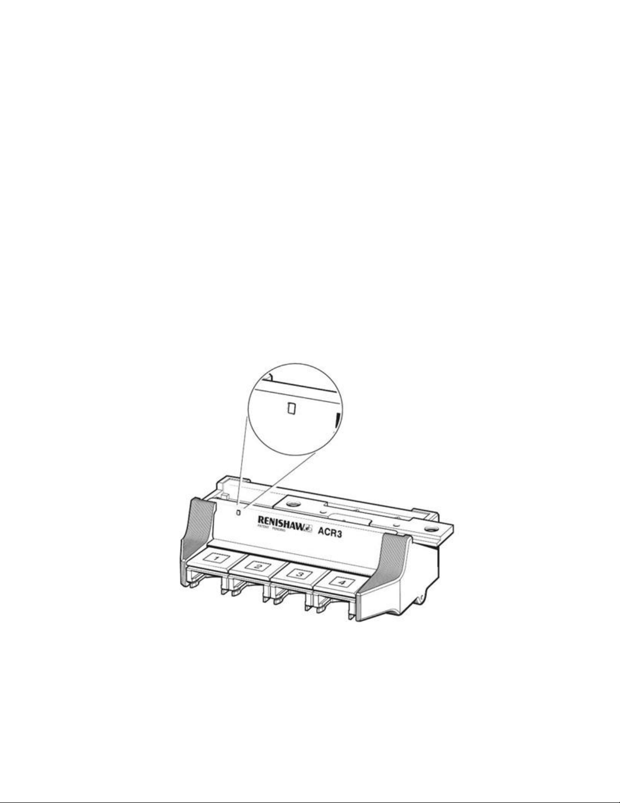
22. With the head located in port 4 move along the ACR3 Y axis using 50 to 100 μm DCC moves until
the alignment circle is positioned in the centre of the alignment window. Record a point (point C) in this
position (see below, for reference).
23. The probe Y axis offset now has to be calculated
probe Y offset = Y axis position of point C – 62.6 mm
24. Apply the Y probe offset to all the ACR3 axis systems:
Recall portx axis as constructed in step 17.
10/12/2010file://C:\Temp\~hh63CD.htm
Page 39

Page 39 of 45ACR3 installation and user's guide
Translate the Y axis datum position by probe Y offset.
Store as portx axis.
25. Calculate the ACR3 traverse distance (distance):
Recall port1 axis.
Recall port1 locked circle (refer to step 11) the Y axis position of this feature is the traverse distance
for the ACR3 (distance).
26. This traverse distance is then used in the load/unload
routines.
10/12/2010file://C:\Temp\~hh63CD.htm
Page 40
Page 40 of 45ACR3 installation and user's guide
ACR3changeroutine
CAUTION: During various stages of this recommended change routine the probe signal is inhibited.
The trigger line cannot therefore be used to reliably indicate the probe system status.
Loadroutine
All movements are absolute moves in mm and in respective port X axis system.
X position Y position Z position
Recall port* axis
Stand-off position 40 0 7
Entry into port 0 0 7
Connect female autojoint 0 0 0
Move to lock autojoint 0 Distance
(refer to step 25 of Datuming ACR3 web
Move to lift off position 0 Distance
(refer to step 25 of Datuming ACR3 web
Exit port 40 Distance
(refer to step 25 of Datuming ACR3 web
Enable probe signal
NOTE: Due to forces exerted by the autochange operation on the head, it is strongly recommended
that the head is unlocked and re-locked immediately after picking up a probe, in order to maintain
repeatability.
page)
page)
page)
Unloadroutine
All movements are absolute moves in mm and in respective portx axis system.
0
0.1
0.1
X position Y position Z position
Recall port* axis
Stand-off position 40 Distance
(refer to step
25)
0.1
10/12/2010file://C:\Temp\~hh63CD.htm
Page 41

Page 41 of 45ACR3 installation and user's guide
Inhibit probe signal
Entry into port 0 Distance
(refer to step
Move to unlock autojoint 0 0 0.1
Release from the femail autojoint 0 0 7
Exit port 40 0 7
25)
0.1
10/12/2010file://C:\Temp\~hh63CD.htm
Page 42

Troubleshooting
Fault Possible cause Solution
Page 42 of 45ACR3 installation and user's guide
Black deposit on probe
autojoint.
Excessive wear on ACR3
port.
ACR3 does not run
smoothly.
Badly aligned probe head.
Badly aligned ACR3.
Badly aligned probe head.
Badly aligned ACR3.
Approaching the expected
life of the ACR3 port.
Badly aligned probe head.
Badly aligned ACR3.
Damage occured to ACR3.
Re-align probe head - refer to 'Head
alignment'.
Re-datum ACR3 - refer to 'Datuming the
.
ACR3'
Re-align probe head - refer to 'Head
alignment'
Re-datum ACR3 - refer to 'Datuming the
ACR3'.
Replace the port- refer to 'Accessories/spare
parts' and 'Maintenance'.
Re-align probe head - refer to 'Head
alignment'
Re-datum ACR3 - refer to 'Datuming the
ACR3'.
Return the ACR3 to the local Renishaw
service centre.
.
.
Head obstructing during
ACR3 lock.unlock
sequence.
Badly aligned probe head.
Badly aligned ACR3
Attempting to "stack"
extension bars.
Damage occured to ACR3.
Re-align probe head - refer to 'Head
alignment'
Re-datum ACR3 - refer to 'Datuming the
ACR3'.
The ACR3 system has not been designed to
support the stacking of extension bars.
Return the ACR3 to the local Renishaw
service centre.
.
10/12/2010file://C:\Temp\~hh63CD.htm
Page 43

Page 43 of 45ACR3 installation and user's guide
ACR3accessoriesandspareparts
As the ACR3 is part of a modular system offered by Renishaw, all part numbers for the ACR3 system,
the MRS system and other components that can be fitted to the rack are specified below:
ACR3 system
ACR3 4 port rack kit (includes tooling) A-5036-0005
Spares
ACR3 setting gauge M-5036-0004
Lid clip M-1051-0043
'T' nut P-NU18-0005
Long 'T' nut M-5036-0055
Port replacement kit (4 ports) A-5036-0049
MRS system
MRS rack 400 mm long A-4192-0050
600 mm long A-4192-005
1000 mm long A-4192-0052
Spares
MRS leg 125 mm long A-4192-0053
62.5 mm long A-4192-0061
MRS feet A-4192-0055
MRS stand off adaptor A-4192-0058
MRS leg to foot adaptor A-4192-0055
Plastic end cap P-BG03-0014
SCP600 (stylus change port for the SP600 probe)
SCP600 port (includes tooling) A-2098-0933
Spares
Stylus spanner M-5000-3707
10/12/2010file://C:\Temp\~hh63CD.htm
Page 44

Page 44 of 45ACR3 installation and user's guide
Maintenance
Each ACR3 rack port is of modular design to permit easy replacement by the user should wear occur
during the operational life of the ACR3. There are no other user serviceable parts, should the unit
become defective it should be returned to the local Renishaw service centre.
Cleaning
The ACR3 is not a sealed unit. Cleaning of the ACR3 should therefore be restricted to the use of a clean
dry cloth.
Portreplacement
CAUTION: The ACR3 is positioned in the working envelope of the CMM, it is recommended that
power is removed from the CMM servos throughout the port replacement procedure.
Port replacement is carried out using the following procedure:
1. Release and remove the two M3 x 6 mm long screws and remove the port(s) to be replaced.
2. Loosen the M3 x 6 mm long screws securing the remaining ports in preparation for final
alignment.
3. Position the replacement port(s) onto the rack and loosely screw in place.
4. Open all the port lids using the lid clips supplied with the ACR3.
5. Place a rigid straight edge along the underside of all the ports and tighten all M3 x 6 mm long
screws to 0.3 Nm. It is very important that the ports are correctly aligned.
6. Remove straight edge and lid clips.
7. Re-datum the rack (see ‘
Datuming of the ACR3’).
10/12/2010file://C:\Temp\~hh63CD.htm
Page 45

Page 45 of 45ACR3 installation and user's guide
10/12/2010file://C:\Temp\~hh63CD.htm
 Loading...