

RenewAire RH-D TER-6-2208, RH-DTER-6-1120, RH-D TER-6-2240, RH-D TER-8-4208, RH-D TER-8-3240 Installation, Operation & Maintenance Manual
...
ELECTRIC DUCT HEATER
LR 30551
INSTALLATION, OPERATION & MAINTENANCE MANUAL
RH-D Series
RH-W Series
Model RH-D Shown
WWW.RENEWAIRE.COM

RH-D AND RH-W ELECTRIC DUCT HEATERS
IMPORTANT SAFETY INFORMATION
WARNING
ARC FLASH AND ELECTRIC SHOCK HAZARD
All models of Electric Heaters as discussed in this manual operate
on high voltages that can cause severe electric shock. Some
models of Electric Heaters use high voltages that are capable
of causing dangerous arc flash. Whenever accessing any part or
component of the heater, disconnect all electric power supplies,
verify with a voltmeter that electric power is OFF and wear
protective equipment per NFPA 70E when working within the
electric enclosure. Failure to comply can cause serious injury
or death.
The terminal blocks contain live high-voltage.
The only way to ensure that there is NO voltage inside the unit
is to install and open a remote disconnect switch and verify that
power is off with a voltmeter. Refer to unit electrical schematic.
Follow all local codes.
CAUTION
CAUTION
RISK OF ELECTRIC SHOCK OR EQUIPMENT DAMAGE
Whenever electrical wiring is connected, disconnected or
changed, the power supply to the electric heater and its controls
must be disconnected. Lock and tag the disconnect switch or
circuit breaker to prevent accidental reconnection of electric
power.
CAUTION
RISK OF BURNS
This device is an electric heater and produces very high
temperatures, capable of causing severe burns. Use caution
when working on the heater and wear appropriate Personal
Protective Equipment (PPE) whenever working on the unit.
IMPORTANT
This equipment is to be installed by following Industry Best
Practices and all applicable codes. Any damage to components,
assemblies or subassemblies which is caused by improper
installation practices will void the warranty.
AVERTISSEMENT
RISQUE FLASH D’ARC OU DE CHOC ÉLECTRIQUE GRAVE
Tous les modèles de radiateurs électriques décrits dans ce manuel
fonctionnent avec des tensions élevées pouvant causer un choc
électrique grave. Certains modèles de radiateurs électriques
utilisent des tensions élevées susceptibles de provoquer des arcs
électriques dangereux. Lorsque vous accédez à une pièce ou à un
composant du chauffe-eau, débranchez toutes les alimentations
électriques, vérifiez avec un voltmètre que le courant est coupé
et portez un équipement de protection conformément à NFPA
70E lorsque vous travaillez dans le boîtier électrique. Ne pas se
conformer peut entraîner des blessures graves ou la mort.
Les borniers contiennent une haute tension sous tension.
Le seul moyen de s’assurer qu’il n’ya PAS de tension à l’intérieur
de l’unité est d’installer et d’ouvrir un sectionneur à distance et de
vérifier que l’alimentation est coupée avec un voltmètre. Reportezvous au schéma électrique de l’unité.
Suivez tous les codes locaux.
CAUTION
ATTENTION
RISQUE DE CHOC ÉLECTRIQUE OU DE DOMMAGES MATERIELS
Chaque fois que le câblage électrique est connecté, déconnecté
ou modifié, l’alimentation électrique du radiateur électrique
et de ses commandes doit être déconnectée. Verrouillez et
étiquetez le sectionneur ou le disjoncteur pour empêcher toute
reconnexion accidentelle de l’alimentation électrique.
CAUTION
ATTENTION
RISQUE DE BRÛLURES
Cet appareil est un radiateur électrique et est capable de produire
des températures très élevées, susceptibles de provoquer de
graves brûlures. Soyez prudent lorsque vous travaillez sur le
radiateur et portez un équipement de protection individuelle
(EPI) approprié lorsque vous travaillez sur l’appareil.
IMPORTANT
Only persons who have been properly trained and authorized
are to access the electric heater and its controls. Changes to
the electric heater wiring and controls are to be made only by
trained and authorized personnel.
RENEWAIRE.COM INSTALLATION, OPERATION AND MAINTENANCE MANUAL 1.800.627.44992

RH-D AND RH-W ELECTRIC DUCT HEATERS
UNIT RECORDS
Record information as shown below. In the unlikely event that factory assistance is ever required, this
information will be needed.
OWNER INFORMATION
Locate the RenewAire unit label, to be found on the outside of the appliance.
NOTE: This information is for purposes of identifying the specific appliance. Unit-specific option data can
then be obtained, as needed, from the Model Number.
Electric Duct Heater Type: (D or W)
Electric Duct Heater Model:
Serial Number:
R H
-
- -
NOTE: This page is to
be completed by the
installing contractor.
The completed
document is to be turned over
to the owner after start-up.
3 1.800.627.4499 INSTALLATION, OPERATION AND MAINTENANCE MANUAL RENEWAIRE.COM

OWNER INFORMATION
RH-D AND RH-W ELECTRIC DUCT HEATERS
TABLE OF CONTENTS
IMPORTANT SAFETY INFORMATION 2
UNIT RECORDS 3
1.0 OVERVIEW 5
1.1 DESCRIPTION 5
1.2 APPLICATIONS 5
1.3 SAFETY FEATURES 5
1.3.1 Low Air Flow Modulation / Shut Off 5
1.3.2 Auto-Reset Thermal Cutout 5
1.3.3 Manual Reset Thermal Cutout 5
1.3.4 Maintenance 5
1.4 AIRFLOW DIRECTION 5
1.4.1 RH-D 5
1.4.2 RH-W 5
1.5 RH-D AND RH-W MODELS 6
2.0 COMPONENT DESCRIPTION 7
2.1 RH-D 7
2.2 RH-W 8
2.2.1 CTH291 Thermostat 8
2.3 COMPANION ACCESSORIES 9
2.3.1 Occupancy Sensor 9
2.3.2 Timer 9
3.0 DIMENSIONED DRAWINGS 10
3.1 RH-D AND RH-W WITH 6” DUCT COLLAR 10
3.2 RH-D AND RH-W WITH 8” DUCT COLLAR 10
3.3 RH-D AND RH-W WITH 10” DUCT COLLAR 11
3.4 RH-D AND RH-W WITH 12” DUCT COLLAR 11
4.0 UNIT WEIGHTS 12
4.1 RH-D AND RH-W WITH 6” DUCT 12
4.2 RH-D AND RH-W WITH 8” DUCT 12
4.3 RH-D AND RH-W WITH 10” OR 12” DUCTS 12
5.0 INSTALLATION 12
5.1 MINIMUM AIRFLOW REQUIREMENTS 12
5.2 INSTALLATION LOCATION 12
5.3 UNIT ORIENTATION 12
5.4 INSTALLATION CLEARANCES 12
5.5 DUCTWORK CONNECTIONS 12
5.6 DUCTWORK INSULATION 13
5.7 VERIFY AIRFLOW DIRECTION (RH-D UNITS ONLY) 13
5.8 CONNECT ELECTRIC SERVICE 13
5.8.1 Line Voltage Wiring Entry Point 13
5.9 CONNECT THERMOSTAT (RH-W ONLY) 13
5.9.1 Low Voltage Wiring Entry Point (RH-W Only) 17
5.10 SET CONTROLLER POTENTIOMETER (RH-D ONLY) 17
6.0 WIRING SCHEMATICS 18
6.1 RH-D 120 VAC 18
6.2 RH-D 208/240 VAC (1,2,3,4,5 AND 6 KW) 18
6.3 RH-D 208/240 VAC (8,10 AND 11.5 KW) 19
6.4 RH-W 120 VAC 19
6.5 RH-W 208/240 VAC (3,4,5,6 KW) 20
6.6 RH-W 208/240 VAC (8,10,11.5 KW) 20
7.0 MAINTENANCE 21
7.1 RH-D ANNUAL MAINTENANCE 21
7.2 RH-W ANNUAL MAINTENANCE 21
7.3 RH-D TROUBLE SHOOTING 21
7.3.1 Testing AFS and S1 Sensors 21
7.3.2 Testing Control Modules D21-T and D22-T 21
7.3.3 Testing Heating Elements 22
7.3.4 Testing the Transformer 22
7.4 RH-W TROUBLE SHOOTING 22
7.4.1 Testing the CTH291 Thermostat 22
7.4.2 Testing the S2 Airflow Sensor 22
7.4.3 Testing the PSSR Control Module 22
7.4.4 Testing the SSR 23
7.4.5 Testing the Heating Elements 23
7.4.6 Testing the Transformer 23
7.5 SEQUENCE OF OPERATION 23
7.5.1 RH-D Heaters 23
7.5.2 RH-W Heaters 24
8.0 FACTORY ASSISTANCE 24
9.0 WARRANTY 24
10.0 REPAIR PARTS 25
10.1 RH-D 1,2,3,4,5,6 KW REPAIR PARTS 25
10.2 RH-D 8,10,11.5 KW REPAIR PARTS 25
10.4 RH-W 8,10,11.5 KW REPAIR PARTS 26
10.3 RH-W 1,2,3,4,5,6 KW REPAIR PARTS 26
11.0 ENGINEERING AND PERFORMANCE DATA 27
TABLE OF ILLUSTRATIONS
RH-D Heater (typ) 7
RH-D Controls (typ) 7
RH-W Heater (typ) 8
RH-W Controls (typ) 8
Wall Thermostat (typ) 8
MC-C Occupancy Sensor, Ceiling Mount 9
TC7D-W Wall Mount Time Clock 9
MC-W Occupancy Sensor, Wall Mount 9
TC7D-E Time Clock 9
RH-D and RH-W 6” Duct Collar Dimensioned Dwg 10
RH-D and RH-W 8” Duct Collar Dimensioned Dwg 10
RH-D and RH-W 10” Duct Collar Dimensioned Dwg 11
RH-D 12” Duct Collar Dimensioned Dwg 11
Ventilation Clearance 12
Thermostat Wiring Illustration 15
DIP Switch Positions 15
Comfort Mode Screen Shot 16
Economy Mode Screen Shot 16
Wiring Termination Illustration 17
RH-D 1,2,3,4,5,6 KW Repair Parts 25
RH-D 8,10,11,5 KW Repair Parts 25
RH-W 1,2,3,4,5,6 KW Repair Parts 26
RH-W 8,10,11.5 KW Repair Parts 26
RENEWAIRE.COM INSTALLATION, OPERATION AND MAINTENANCE MANUAL 1.800.627.44994

RH-D AND RH-W ELECTRIC DUCT HEATERS
OVERVIEW
1.0 OVERVIEW
1.1 DESCRIPTION
The RH-D and RH-W heaters are open-coil, electric resistance duct heaters that come in several
different models with different wattages and duct sizes. The RH-D heater has an internal temperature
sensor mounted in the outlet side of the unit and has an adjustable thermostat that determines what
the outlet air temperature is to be. The controller then modulates current to the heating coil to maintain
that temperature setting. The RH-W heater requires an external analog 0 - 10 VDC control signal,
supplied by wall-mount thermostat, a RenewAire Premium Commercial Controller or a BMS. A wallmount thermostat is provided with each RH-W unit. Every heater is equipped with an airflow sensor to
detect minimum allowable airflow. If there is inadequate airflow, current to the heating coils is reduced
to a level that corresponds to the detected airflow volume. All heaters use a Solid State Relay (SSR) to
modulate the heat output.
1.2 APPLICATIONS
These heaters are ideally suited for use in tempering air that is delivered directly to an Occupied Space
or they can also be used as a primary heat source. They can be used as pre-heat or post-heat devices
in conjunction with an ERV or a DOAS. The RH-D can operate independantly by setting an on-board
potentiometer to maintain a constant output temperature while the RH-W uses an external temperature
control signal (wall thermostat) to modulate the heat output. These heaters are suitable for use in both
residential and commercial applications.
1.3 SAFETY FEATURES
1.3.1 Low Air Flow Modulation / Shut Off
The heater has a thermistor air flow sensor that will detect any overheating condition caused by low
air flow. The sensor has a threshold of 111º F [44º C]. If a temperature higher than 111º F is detected,
it will cause the controller to begin reducing the pulse width of the control signal being sent to the SSR.
The reduction in pulse width begins at a detected temperature of 111º F and the reduction will increase
proportionally up to a detected temperature of 124º F [51º C], at which point the sensor will shut off the
control signal to the SSR. In this mode, the unit’s Red (or Yellow) warning light is ON steady.
NOTE: This unit is a
high-voltage open coil
electric heater, used for
both commercial and residential applications. It is commonly referred to in this manual
as an “electric heater”.
1.3.2 Auto-Reset Thermal Cutout
The heater has an auto-reset thermal cutout having a threshold of 125º F. If a temperature higher than
125º F is detected, the auto-reset cutout will shut off power to the heater element. Once the detected
temperature drops below 125º F, the cutout will reset itself and restore power to the heater element.
1.3.3 Manual Reset Thermal Cutout
The heater has a manual reset thermal cutout having a threshold of 200º F. If a temperature higher
than 200º F is detected, power to the heater element is shut off until the heater cools and the cutout
is manually reset.
1.3.4 Maintenance
There is no required annual maintenance for these units.
1.4 AIRFLOW DIRECTION
1.4.1 RH-D
Airflow direction in the RH-D must be coordinated with the Output Air Temperature Sensor. The sensor
must be located on the outlet side of the unit in order to properly monitor the output temperature.
See the illustrations on page 7. If airflow direction other than as shown is desired, the sensor must be
relocated to the alternate location, as shown.
1.4.2 R H-W
Airflow direction in the RH-W can be in either direction, with no changes to the unit hardware.
5 1.800.627.4499 INSTALLATION, OPERATION AND MAINTENANCE MANUAL RENEWAIRE.COM
OVERVIEW
6" 8" 10" 12"
1 2 3 4 5 6 8 10 11.5 120 208 240
RH-D
TER-6-1120
l l l
131320
RH-D
TER-6-1208
l l l
131352
RH-D
TER-6-1240
l l l
131353
RH-D
TER-6-2120
l l l
131321
RH-D
TER-6-2208
l l l
131354
RH-D
TER-6-2240
l l l
131355
RH-D
TER-8-3208
l l l
131356
RH-D
TER-8-3240
l l l
131322
RH-D
TER-8-4208
l l l
131357
RH-D
TER-8-4240
l l l
131323
RH-D
TER-8-5208
l l l
131358
RH-D
TER-8-5240
l l l
131359
RH-D
TER-8-6240
l l l
131360
RH-D
TER-10-3208
l l l
131336
RH-D
TER-10-3240
l l l
131337
RH-D
TER-10-4208
l l l
131338
RH-D
TER-10-4240
l l l
131339
RH-D
TER-10-5208
l l l
131340
RH-D
TER-10-5240
l l l
131341
RH-D
TER-10-6240
l l l
131342
RH-D
TER-10-8240
l l l
131343
RH-D
TER-10-10240
l l l
131361
RH-D
TER-10-12240
l l l
131362
RH-D
TER-12-6240
l l l
131344
RH-D
TER-12-8240
l l l
131345
RH-D
TER-12-10240
l l l
131346
RH-D
TER-12-12240
l l l
131347
RH-W
ZON-6-1120
l l l
131324
RH-W
ZON-6-1208
l l l
131363
RH-W
ZON-6-1240
l l l
131364
RH-W
ZON-6-2120
l l l
131325
RH-W
ZON-6-2208
l l l
131365
RH-W
ZON-6-2240
l l l
131366
RH-W
ZON-8-3208
l l l
131367
RH-W
ZON-8-3240
l l l
131326
RH-W
ZON-8-4208
l l l
131368
RH-W
ZON-8-4240
l l l
131327
RH-W
ZON-8-5208
l l l
131369
RH-W
ZON-8-5240
l l l
131370
RH-W
ZON-8-6240
l l l
131371
RH-W
ZON-10-3208
l l l
131328
RH-W
ZON-10-3240
l l l
131329
RH-W
ZON-10-4208
l l l
131330
RH-W
ZON-10-4240
l l l
131331
RH-W
ZON-10-5208
l l l
131332
RH-W
ZON-10-5240
l l l
131333
RH-W
ZON-10-6240
l l l
131334
RH-W
ZON-10-8240
l l l
131348
RH-W
ZON-10-10240
l l l
131372
RH-W
ZON-10-12240
l l l
131373
RH-W
ZON-12-6240
l l l
131335
RH-W
ZON-12-8240
l l l
131349
RH-W
ZON-12-10240
l l l
131350
RH-W
ZON-12-12240
l l l
131351
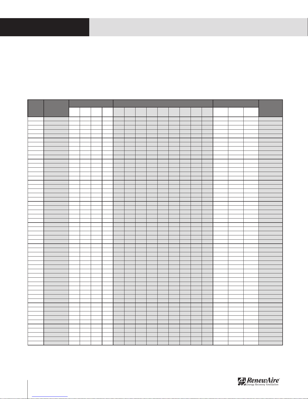
RenewAire
Part
Number
Heater
Type
Model
Duct Collar Size Kilowattage Voltage (1 Phase Only)
RH-D AND RH-W ELECTRIC DUCT HEATERS
1.5 RH-D AND RH-W MODELS
Both the RH-D and RH-W heaters are available in several different duct sizes and wattages. Note that
type RH-D uses an internal temperature sensor to regulate the heat output while type RH-W uses a
wall-mount thermostat that operates on 24 VAC, which is provided with the heater. The RH-W can also
be controlled by a Building Management System, or BMS.
RENEWAIRE.COM INSTALLATION, OPERATION AND MAINTENANCE MANUAL 1.800.627.44996

RH-D AND RH-W ELECTRIC DUCT HEATERS
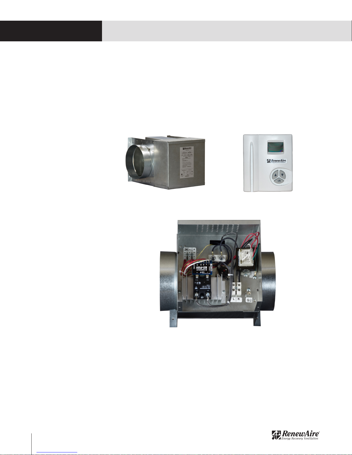
2.0 COMPONENT DESCRIPTIONS
2.1 RH-D
RH-D heaters use open coil, electric resistance hardware to provide an adjustable heat output. An
airflow sensor is provided, checking for minimum airflow. There are two separate thermal cutout
devices, the first of which will shut down the heater at 125
there is a second cutout that will shut down the heater at 2000 F. The second cutout must be manually
reset. The controller operates on 24 VAC provided by an on-board transformer. The controller has a
potentiometer to set the desired output air temperature from the unit and heat output is modulated by
the controller, which causes the SSR to provide pulsed current to the heating coil.
0
F and then automatically reset itself and
COMPONENT DESCRIPTION
Manual Reset Thermal Cutout
(2000 F)
RH-D Heater (typ)
Airflow Sensor
(checks for minimum airflow)
Manual Reset Thermal Cutout
(2000 F)
Air Temperature Sensor as
Shipped From Factory
Output Air Temperature Sensor
(must be installed on the outlet
side)
Auto Reset Thermal Cutout
(1250 F)
Alternate Air Temperature Sensor Location
(move the sensor here if airflow direction
is reversed)
Potentiometer for Setting
Desired Output Air
Temperature
Airflow Direction as
Shipped From Factory
LED Indicator Light
(turns ON to show when
power is going to the
heating coils)
RH-D Controls (typ)
7 1.800.627.4499 INSTALLATION, OPERATION AND MAINTENANCE MANUAL RENEWAIRE.COM
COMPONENT DESCRIPTION
RH-D AND RH-W ELECTRIC DUCT HEATERS
2.2 RH-W
RH-W heaters use open coil, electric resistance hardware to provide an adjustable heat output. An
airflow sensor is provided, checking for minimum airflow. There are two separate thermal cutout
devices, the first of which will shut down the heater at 125
there is a second cutout that will shut down the heater at 2000 F. The second cutout must be manually
reset. The controller operates on 24 VAC provided by an on-board transformer. Output temperature is
controlled by an analog 0-10 VAC signal provided by either an optional wall thermostat, a BMS or by a
RenewAire Premium Programmable Controller. The heat output of the unit is modulated by means of
pulsed current supplied to the heating coils by the SSR, which is controlled by the on-board controller.
0
F and then automatically reset itself and
RH-W Heater (typ)
RH-W Controls (typ)
Wall Thermostat (typ)
2.2.1 CTH291 Thermostat
The CTH291 Thermostat is an 0 - 10 VDC output, dual mode device. It provides an analog 0 - 10 VDC
output signal to the RH-W controller, enabling the controller to modulate the heat output, as needed. It
has a Comfort mode and an Economy mode, which is a temperature setback of 80 F. Comfort Mode is
the standard mode of operation and Economy mode can only be enabled if there is either an occupancy
sensor or a timer wired to the thermostat. Economy mode will remain active until the Normally Closed
(NC) contacts on either the timer or the occupancy sensor open, indicating an occupied condition
for the Occupied Space. When the NC contacts open, the device will switch back to Comfort mode
automatically. While the thermostat is in Economy mode, the mode can be overridden by pressing the
UP or DOWN arrow buttons to change the setpoint and then pressing the hand button to enter the new
setpoint. This override condition remains in effect for two hours.
RENEWAIRE.COM INSTALLATION, OPERATION AND MAINTENANCE MANUAL 1.800.627.44998

RH-D AND RH-W ELECTRIC DUCT HEATERS
2.3 COMPANION ACCESSORIES
2.3.1 Occupancy Sensor
RenewAire offers both ceiling mount and wall mount occupancy sensors as options for the Electric
Duct Heater. Either device must be hard-wired to the CTH291 thermostat and powered by an external
24 VAC source.
COMPONENT DESCRIPTION
MC-C Occupancy Sensor, Ceiling Mount
MC-W Occupancy Sensor, Wall Mount
2.3.2 Timer
RenewAire offers a commercial-grade timer as an option for the CTH291 Thermostat. The timer may
be pre-set to switch the thermostat from Economy mode to Comfort mode.
TC7D-W Wall Mount Time Clock
TC7D-E Time Clock
9 1.800.627.4499 INSTALLATION, OPERATION AND MAINTENANCE MANUAL RENEWAIRE.COM

DIMENSIONED DRAWINGS
RH-D AND RH-W ELECTRIC DUCT HEATERS
3.0 DIMENSIONED DRAWINGS
3.1 RH-D AND RH-W WITH 6” DUCT COLLAR
RH-D and RH-W 6” Duct Collar Dimensioned Dwg
3.2 RH-D AND RH-W WITH 8” DUCT COLLAR
RENEWAIRE.COM INSTALLATION, OPERATION AND MAINTENANCE MANUAL 1.800.627.449910
RH-D and RH-W 8” Duct Collar Dimensioned Dwg

RH-D AND RH-W ELECTRIC DUCT HEATERS
3.3 RH-D AND RH-W WITH 10” DUCT COLLAR
DIMENSIONED DRAWINGS
RH-D and RH-W 10” Duct Collar Dimensioned Dwg
3.4 RH-D AND RH-W WITH 12” DUCT COLLAR
RH-D 12” Duct Collar Dimensioned Dwg
11 1.800.627.4499 INSTALLATION, OPERATION AND MAINTENANCE MANUAL RENEWAIRE.COM

INSTALLATION
RH-D AND RH-W ELECTRIC DUCT HEATERS
4.0 UNIT WEIGHTS
4.1 RH-D AND RH-W WITH 6” DUCT
All Electric Duct Heaters with 6” diameter duct collars weigh 9 pounds.
4.2 RH-D AND RH-W WITH 8” DUCT
All Electric Duct Heaters with 8” diameter duct collars weigh 12 pounds.
4.3 RH-D AND RH-W WITH 10” OR 12” DUCTS
All units having duct collars of either 10” or 12” and a capacity of up to 6 KW weigh 16 pounds. Units
having a capacity greater than 6 KW weigh 21 pounds.
5.0 INSTALLATION
5.1 MINIMUM AIRFLOW REQUIREMENTS
All heaters require a minimum airflow in order to operate properly. The rule of thumb is that 30 CFM is
required for each kilowatt of electric heat. See the chart in Section 1.2 of this manual. If airflow through
the heater is less than 30 CFM per kilowatt, the airflow sensor will detect the reduced airflow and will
cause the controller to modulate the heat output to a level that is consistent with the airflow volume
sensed in the heater. See the illustration on Page 7 of this manual.
5.2 INSTALLATION LOCATION
The Electric Duct Heater should be installed as near as possible to the Occupied Space in order to
reduce heat loss from duct runs.
5.3 UNIT ORIENTATION
All RH-D and RH-W heaters may be installed either horizontally or vertically. When installed horizontally,
the unit top must be installed UP. See image below. There is a removable sheet metal cover installed on
the top that covers the auto reset temperature cutout and the airflow sensor.
5.4 INSTALLATION CLEARANCES
All RH-D and RH-W Electric Heaters are rated for 0 clearance to combustible surfaces. There are
ventilation openings in the top and bottom of the unit control box that require a minimum of 1/2 inch
clearance for cooling of the control box. If any heater is installed horizontally, maintain a minimum
of 1/2 inch clearance above and beneath the unit. In addition, any heater that is installed vertically
must maintain a clearance of 1 inch for a distance of 6 feet downstream from the heater.
Ventilation Openings on Both Top and Bottom
(leave a minimum of 1/2 inch clearance
above and beneath the unit)
5.5 DUCTWORK CONNECTIONS
Ductwork connections are to be made in accordance with SMACNA guidelines. All ductwork and its
insulation must be rated for a minimum of 200 degrees F. Ductwork should be attached with both
mechanical fasteners and UL 181 - rated duct mastic. DO NOT INSTALL ANY DUCTWORK ELBOWS
CLOSER THAN 2.5 TIMES THE DUCT DIAMETER TO THE HEATER.
RENEWAIRE.COM INSTALLATION, OPERATION AND MAINTENANCE MANUAL 1.800.627.449912
Ventilation Clearance

RH-D AND RH-W ELECTRIC DUCT HEATERS
5.6 DUCTWORK INSULATION
The Supply Air ductwork leading from the output side of the heater to the Occupied Space should be
insulated to prevent heat loss. Individual jobsite conditions will dictate whether the duct leading to the
inlet side of the heater should also be insulated. In some cases, the air being supplied to the heater
is coming from an Energy Recovery Ventilator (ERV) and the connecting duct passes through a space
that is not conditioned. In this case, the ductwork from the ERV to the heater should also be insulated.
5.7 VERIFY AIRFLOW DIRECTION (RH-D UNITS ONLY)
The Outlet Air Temperature Sensor must be positioned on the outlet side of the heater. Check the airflow
direction through the heater. If necessary, move the sensor to the outlet side, as shown in Section 2.1
of this manual.
5.8 CONNECT ELECTRIC SERVICE
INSTALLATION
WARNING
ARC FLASH AND ELECTRIC SHOCK HAZARD
All models of Electric Heaters as discussed in this manual operate on high voltages that can cause
severe electric shock. Some models of Electric Heaters use high voltages that are capable of
causing dangerous arc flash. Whenever accessing any part or component of the heater, disconnect
all electric power supplies, verify with a voltmeter that electric power is OFF and wear protective
equipment per NFPA 70E when working within the electric enclosure. Failure to comply can cause
serious injury or death.
The terminal blocks contain live high-voltage.
The only way to ensure that there is NO voltage inside the unit is to install and open a remote
disconnect switch and verify that power is off with a voltmeter. Refer to unit electrical schematic.
Follow all local codes.
CAUTION
CAUTION
RISK OF ELECTRIC SHOCK OR EQUIPMENT DAMAGE
Whenever electrical wiring is connected, disconnected or changed, the power supply to the electric
heater and its controls must be disconnected. Lock and tag the disconnect switch or circuit breaker
to prevent accidental reconnection of electric power.
5.8.1 Line Voltage Wiring Entry Point
High voltage electric service is to be brought into the unit through one of the factory-provided knockouts
located on the side of the control box. Wiring is to be terminated on the terminal block and grounding
lug as shown in the photo in Section 5.9.1 of this manual. Also see the wiring schematics in Section
8.0 of this manual. Observe all local codes.
5.9 CONNECT THERMOSTAT (RH-W ONLY)
RH-W heaters require an external 0 - 10 VDC signal to control the heater output. This is normally
accomplished by using a CTH291 wall thermostat, which also requires 24 VAC to operate. The low
voltage thermostat wiring should enter the heater through the second knockout located on the side
of the control box. Wiring is to be terminated as shown in the wiring schematics in Section 6.0 of this
manual.
13 1.800.627.4499 INSTALLATION, OPERATION AND MAINTENANCE MANUAL RENEWAIRE.COM

INSTALLATION
RH-D AND RH-W ELECTRIC DUCT HEATERS
CAUTION
CAUTION
RISK OF ELECTRIC SHOCK OR EQUIPMENT DAMAGE
Whenever electrical wiring is connected, disconnected or changed, the power supply to the electric
heater and its controls must be disconnected. Lock and tag the disconnect switch or circuit breaker
to prevent accidental reconnection of electric power.
Each thermostat is provided with a mounting base plate and all necessary mounting hardware.
• Mount the base plate on the wall using provided anchors and screws or mount it directly on a
standard 2 X 4 electrical junction box..
• Open the thermostat housing by removing two screws on the bottom of the thermostat and lift
the cover off.
• Pull low voltage wiring through the opening in the back of the thermostat and then mount the
thermostat on the base plate using the provided two short screws.
• Connect low voltage wiring as shown in illustration at right.
• Set the DIP switches to desired settings. See chart and illustration at right.
• Reinstall the front cover.
• Reconnect power to the heater, which will provide 24 VAC to the thermostat.
Install base plate on wall using provided
hardware or mount directly on standard 2 X 4
electrical junction box.
Remove two screws from bottom
of thermostat and lift cover off.
Pull low-voltage wiring through
opening in the back of the
thermostat and then attach
thermostat to base plate using
the provided two short screws.
RENEWAIRE.COM INSTALLATION, OPERATION AND MAINTENANCE MANUAL 1.800.627.449914

Provide field wiring from these
three terminals to terminal lugs
on RH-W controller. See wiring
schematics 6.4, 6.5 and 6.6 in
this manual.
Connect optional Occupancy
Sensor or Timer to terminals
4 and 5. Use Normally
Closed (NC) contacts. When
contacts open (or if no
sensor or timer is present),
thermostat will operate only
in Comfort Mode.
RH-D AND RH-W ELECTRIC DUCT HEATERS
24 VAC Common
24 VAC
0 - 10 VDC
INSTALLATION
SWITCH
1
2
3
4
5
6
7
DIP SWITCH POSITIONS
OFF
O
C
REVERSE ACTING OUTPUT
INTERNAL SENSOR
0 - 10 VDC
NOT USED
RH-W ROOM APPLICATION
NOT USED
Thermostat Wiring Illustration
ON
0
F
NOT USED
NOT USED
NOT USED
FULL SET POINT RANGE
NOT USED
NOT USED
DIP Switch Positions
15 1.800.627.4499 INSTALLATION, OPERATION AND MAINTENANCE MANUAL RENEWAIRE.COM

INSTALLATION
RH-D AND RH-W ELECTRIC DUCT HEATERS
FOR THERMOSTATS THAT DO NOT HAVE EITHER AN OCCUPANCY SENSOR OR A TIMER:
When line voltage is applied to the heater, it automatically provides power to the CTH291 thermostat.
The LCD screen on the thermostat will show the current (ambient) temperature and a small indicator
symbol at the bottom shows whether or not there is a call for heat. If the current setpoint is less
than the ambient temperature, there will be no call for heat and the indicator symbol will remain on
constantly. When the setpoint temperature is greater than the ambient temperature, a call for heat will
be provided by the thermostat to the heater controller and the indicator symbol will blink as long as
there is a call for heat. The thermostat will put out an analog 0 - 10 VDC control signal to the heater
controller, which ramps UP and DOWN slowly.
To change the desired temperature setpoint, press either the UP or DOWN arrow button. The view on
the screen will change from the current ambient temperature to show the active setpoint. To change
the setpoint, continue to press either the UP or DOWN arrow.
• Ambient temperature if not blinking.
• When either UP or DOWN arrow is
pressed briefly, the current setpoint
will show.
• Continue pressing either UP or
DOWN arrows to change the
setpoint.
Comfort Mode Screen Shot
Blinks whenever a call for heat is
being sent to the heater controller
FOR THERMOSTATS THAT HAVE EITHER AN OCCUPANCY SENSOR OR A TIMER CONNECTED:
When an occupancy sensor or a timer is connected to terminals 4 and 5 on the terminal strip (see
illustration on page 15) in the thermostat, the thermostat will go into Economy mode as long as the
NC contacts are closed. When the contacts open, this represents an occupied mode for the Occupied
Space and the thermostat will switch from Economy mode to Comfort mode.
Economy mode can be overridden for up to two hours without the NC contacts opening, and a temporary
setpoint can be installed. Press either the UP or the DOWN arrow button and both the temperature
reading and the indicator dot will blink. Continue pressing the UP and DOWN arrow buttons as needed
to establish the new setpoint and then press the Hand button to enter the new reading.
The Economy mode setpoint is always 80 F less than the Comfort mode setpoint unless it is being
temporarily overridden.
• Indicates thermostat is in Economy
mode.
• Blinks while changing Economy
mode setpoint
RENEWAIRE.COM INSTALLATION, OPERATION AND MAINTENANCE MANUAL 1.800.627.449916
Economy Mode Screen Shot

RH-D AND RH-W ELECTRIC DUCT HEATERS
5.9.1 Low Voltage Wiring Entry Point (RH-W Only)
Low voltage wiring is to be brought into the unit through one of the factory-provided knockouts located
on the side of the control box. See the dimensioned drawings in Section 3.0 of this manual.
Terminate Thermostat
Wiring on Terminal
Block
INSTALLATION
Grounding Lug
Terminate line voltage
wiring here
Wiring Termination Illustration
5.10 SET CONTROLLER POTENTIOMETER (RH-D ONLY)
Set the potentiometer to the desired output temperature from the heater. See the illustration on page
7 of this manual.
17 1.800.627.4499 INSTALLATION, OPERATION AND MAINTENANCE MANUAL RENEWAIRE.COM

WIRING SCHEMATICS
RH-D AND RH-W ELECTRIC DUCT HEATERS
6.0 WIRING SCHEMATICS
6.1 RH-D 120 VAC
RH-D 120 VAC Wiring Schematic
6.2 RH-D 208/240 VAC (1,2,3,4,5 AND 6 KW)
RENEWAIRE.COM INSTALLATION, OPERATION AND MAINTENANCE MANUAL 1.800.627.449918
RH-D 208/240 VAC Wiring Schematic (1,2,3,4,5,6 KW)

RH-D AND RH-W ELECTRIC DUCT HEATERS
6.3 RH-D 208/240 VAC (8,10 AND 11.5 KW)
WIRING SCHEMATICS
6.4 RH-W 120 VAC
RH-D 208/240 VAC Wiring Schematic (8,10,11.5 KW)
RH-W 120 VAC Wiring Schematic
19 1.800.627.4499 INSTALLATION, OPERATION AND MAINTENANCE MANUAL RENEWAIRE.COM

WIRING SCHEMATICS
RH-D AND RH-W ELECTRIC DUCT HEATERS
6.5 RH-W 208/240 VAC (3,4,5,6 KW)
RH-W 208/240 VAC Wiring Schematic (3,4,5,6 KW)
6.6 RH-W 208/240 VAC (8,10,11.5 KW)
RENEWAIRE.COM INSTALLATION, OPERATION AND MAINTENANCE MANUAL 1.800.627.449920
RH-W 208/240 VAC Wiring Schematic (8,10,11.5 KW)

RH-D AND RH-W ELECTRIC DUCT HEATERS
CAUTION
RISK OF BURNS
This device is an electric heater and produces very high temperatures, capable of causing severe
burns. Use caution when working on the heater and wear appropriate Personal Protective Equipment
(PPE) whenever working on the unit.
7.0 MAINTENANCE
7.1 RH-D ANNUAL MAINTENANCE
There is no required annual maintenance for any RH-D heater.
7.2 RH-W ANNUAL MAINTENANCE
RH-W heaters have a fault indicator LED. RenewAire suggests that the LED be checked annually for
indication of detected problems.
7.3 RH-D TROUBLE SHOOTING
7.3.1 Testing AFS and S1 Sensors
MAINTENANCE
Remove AFS and/or S1 sensor from D21-T/D22-T board and measure the ohms across the Thermistor:
The reading should be 10KΩ at 77 F. If the temperature is higher, the resistance will go down and if the
temperature is lower, the resistance will go up. If the sensor reads OPEN LINE, replace sensor.
7.3.2 Testing Control Modules D21-T and D22-T
A D22-T is essentially a D21-T with 2 power outputs instead of one. Here are the steps to follow to test
and troubleshoot these 2 boards:
The first step in testing the D21-T/D22-T controllers is to confirm that there is 24 VAC powering the
board. (Top left connections on the board). The airflow sensor is a device that protects the heater
element section from overheating. If there is a lack of proper airflow, the controller and the airflow
sensor will make the unit modulate proportionally with the airflow. This simply means that, if the
element section is getting half of the needed airflow, the heater will work at half the capacity. This
prevents overheating of the elements which would damage them. For testing purposes, remove the
Airflow sensor (AFS) from the terminals A and A. When that airflow sensor is removed, the heater will
still operate normally but without element protection (this is only for testing). Make sure you reconnect
the airflow sensor after testing.
If there is a built-in duct temperature sensor connected to S and S, you can simply dial your set point
on the blue potentiometer on the controller. If the red light never turns on, temporarily disconnect wires
connected on S and S. The board can still operate but only in an ON/OFF mode. The heater/red light
should turn ON, if the potentiometer is set anywhere between 0 and 18 and OFF anywhere else. Again,
if the red light never turns on, the controller is defective and replacement is required. If the heater is
controlled remotely with a room or duct thermostat, simply set the potentiometer to position “R” (R for
Remote control). Note that these controllers have power outputs. It is possible after many switching
cycles that the built-in triacs will stay stuck in a closed or open position. The control side of the board
might still be good, but the power side will not operate. If the triacs are stuck closed, the thermal cutouts will cut power to the unit. If the triacs are stuck open, the unit will not put out any heat even if
there is a demand.
21 1.800.627.4499 INSTALLATION, OPERATION AND MAINTENANCE MANUAL RENEWAIRE.COM

MAINTENANCE
RH-D AND RH-W ELECTRIC DUCT HEATERS
7.3.3 Testing Heating Elements
Make sure the automatic and manual thermal reset are in the closed position. Measure the resistance
between LOAD 1 on the D21-T board and L2. If the reading is OPEN LINE, replace the heater. If the
board is a D22-T, also measure the resistance between LOAD 2 on the D22-T board and L2. If the
reading is OPEN LINE, replace the heater element.
7.3.4 Testing the Transformer
Power the primary side of the transformer. Measure Voltage across the secondary terminals. Voltage
should be 24 VAC.
7.4 RH-W TROUBLE SHOOTING
7.4.1 Testing the CTH291 Thermostat
Review wiring of thermostat (and sensor, if duct control application). (Refer to instructions supplied
with the thermostat).
Review Dip Switches settings. (Refer to instructions supplied with the thermostat).
Note for Dip switch 2:
Reverse acting: 0-VDC = Full OFF /10VDC = Full ON (RenewAire DEFAULT).
Direct acting: 0-VDC = Full ON/ 10VDC = Full OFF
Troubleshooting notes:
1) If the display is showing two straight lines, the external sensor is defective or not connected to
terminal 7 and 8 (if configured for external sensor – Dip switch 3 = ON). Circuit is open: resistance is
infinite or high.
2) If the temperature sensor is out of measurable range, the display will indicate HI (when the measured
temperature is higher than the top bracket of the temperature range) or Lo (when the measured
temperature is lower than the lower bracket of the temperature
range).
3) Power has to be switch off and on (RESET) after dip switch is changed.
Example: If dip switch 3 is set to external sensor (ON) and no sensor is connected, the screen will show
2 lines; if dip switch 3 is then set to internal sensor (OFF), 2 lines remain as long power has not been
reset.
4) When the thermostat is in heating mode, a sun will appear on the display. It will flash when there is
a call for heat. When the thermostat is in cooling mode, a snow flake will appear on the display. (To set
cooling mode, install a jumper between terminals 2 and 3).
7.4.2 Testing the S2 Airflow Sensor
Remove S2 airflow sensor from PSSR board and measure the ohms across the Thermistor:
The reading should be 10KΩ at 77 F. If the temperature is higher, the resistance will go down and if the
temperature is lower, the resistance will go up. If the sensor reads OPEN LINE, replace sensor.
7.4.3 Testing the PSSR Control Module
Input: 0-10VDC
Shorted or broken Air-Flow sensor detection:
If the air-flow sensing Thermistor connection (A-A) of the D21-PSSR controller is either shorted or
open, the controller will continue to work normally for about 60 seconds. While in this 60 second
period, the yellow (or red) light begins to quickly blink indicating this warning mode. If the normal airflow condition is reinstated within that 60 seconds, the controller goes back to normal operation and
the yellow (or red) light turns OFF. If the normal air-flow condition does NOT come back within the 60
second time frame, the yellow (or red) Warning LED light begins to flash with a pattern of 1-second ON
and 2-seconds OFF, and the controller switches off the SSR output (i.e. lockdown).
To cancel: fix the short or open air-flow sensor connection, and then turn the controller’s power OFF
and then ON.
RENEWAIRE.COM INSTALLATION, OPERATION AND MAINTENANCE MANUAL 1.800.627.449922

RH-D AND RH-W ELECTRIC DUCT HEATERS
Useful diagnostic/ testing process:
To force FULL power to the elements to verify the load current, operation etc. with out requiring
thermostat control.
1. Turn the Power ON.
2. Remove one of the air-flow sensor connections. The yellow (or red) light begins to blink quickly.
3. Short together the air-flow sensor connections (A-A) momentarily for 2-seconds. The program goes
to a “Diagnose Heater” process. The yellow (or red) light keeps blinking. The heater instantly turns
FULL ON, regardless of the 0-10V input voltage.
After 1 minute with FULL ON, the controller turns OFF the elements and the yellow (or red) warning LED
light flashes with a pattern of 1-second ON and 2-seconds OFF.
4. To put to normal operation: Remove the short, connect back the airflow sensor and then turn
controller’s power off and on (to reset).
7.4.4 Testing the SSR
SSR relays are Solid State Relays. They respond to an input signal of 4VDC to 32 VDC. That input is
sent from the controller in the unit. For this reason, it is the normal process to first test the controller
and then proceed with the testing of the relays. The typical failures of relays come from the fact that
those relays are designed to switch a certain number of times. After this, the contact in the relay will
eventually get stuck either in an open position or a closed position. If the contact is stuck closed, the
elements will eventually overheat and the thermal cut-outs will cut the operation of the unit. If the
contact is stuck open, the unit will never heat even when there is a demand for heat. Please note that
heat is the most common source of problem that can damage relays. This is why it is recommended
to have air circulate through the venting holes of the control box. Refer to section “Useful diagnostic/
testing process:” in the PSSR testing procedure to force relays on and off for troubleshooting purposes.
MAINTENANCE
7.4.5 Testing the Heating Elements
Make sure the automatic and manual thermal reset are in the closed position. Measure the resistance
between T on the SSR Relay and L2. If the reading is OPEN LINE, replace the heater.
7.4.6 Testing the Transformer
Apply power to the primary side of the transformer and measure the voltage across the secondary side.
Voltage on the secondary side should be 24 VAC.
7.5 SEQUENCE OF OPERATION
7.5.1 RH-D Heaters
The heater operates on either 120 VAC or 240 VAC, 1 phase, 60 Hz.
The heater will maintain outlet air temperature set by a potentiometer on the controller whenever there
is airflow. Outlet air temperature is sensed by the Outlet Air Temperature Sensor, located on the outlet
side of the unit.
The heater is fully modulated, single stage that is enabled by the Outlet Air Temperature Sensor. See
illustration in Section 2.1 of this manual. The Outlet Air Temperature Sensor is identified as item 5, Duct
Sensor on the Repair Parts drawing.
The heat output of the RH-D is SSR controlled.
• When voltage is applied to the power side of the heater (L/N for 120 VAC, L1/L2 for 240 VAC), the
transformer will send 24 VAC to the control circuit and energize the D21-T controller.
• The Outlet Air Temperature Sensor detects the temperature of the air at the outlet of the heater.
• The controller reads the detected temperature and then modulates the current going to the heater
element as required to maintain the setpoint on the potentiometer. Modulation is accomplished by
the controller sending measured pulses of high voltage AC to the heater element.
• The automatic reset cut-out (1250 F) and the manual reset cut-out (2000 F) will cut off power to
the heating element if overheating within the heater module is detected.
• The Output Air Temperature Sensor (connected to terminals “S” and “S” on the D21-T controller)
must be installed on the outlet side of the heater.
• The electronic Airflow Sensor monitors airflow through the heater and will cause the controller to
reduce current flow to the heater element if there is insufficient airflow.
23 1.800.627.4499 INSTALLATION, OPERATION AND MAINTENANCE MANUAL RENEWAIRE.COM

MAINTENANCE
RH-D AND RH-W ELECTRIC DUCT HEATERS
7.5.2 RH-W Heaters
The heater operates on either 120 VAC or 240 VAC, 1 phase, 60 Hz.
The heater is fully modulated, single stage and is energized by a 0 - 10 VDC signal.
The heat output of the RH-W is SSR controlled.
• When voltage is applied to the power side of the heater (L/N for 120 VAC, L1/L2 for 240 VAC), the
transformer will send 24 VAC to the control circuit and energize the D21-PSSR controller, as well
as provide a 24 VAC output to power the CTH-291 thermostat.
• The CTH-291 thermostat (or other source) commands the heater through terminals “+” and “-”
on the controller.
• Upon receiving a call for heat from the CTH-291 thermostat or other source (such as a BMS), the
controller will output a DC signal to trigger the SSR (Solid State Relay). The SSR will close when
it receives a signal and open when there is no signal. The frequency of the DC signal to the SSR
depends on the 0 - 10 VDC signal coming from the CTH-291 thermostat. At 0 VDC, the heater
will be completely OFF and at 10 VDC, the heater will operate at maximum capacity. Any voltage
between 0 VDC and 10 VDC will result in a proportional output from the heater. The controller
requires a minimum of 0.1 VDC to initiate heating.
• The automatic reset cut-out (1250 F) and the manual reset cut-out (2000 F) will cut off power to
the heating element if overheating within the heater module is detected.
• The electronic Airflow Sensor monitors airflow through the heater and will cause the controller to
reduce current flow to the heater element if there is insufficient airflow.
8.0 FACTORY ASSISTANCE
In the unlikely event that you need assistance from the factory for a specific issue with the RH Electric
Duct Heaters, make sure that you have the information called for in the Unit Records page in the Owner
Information section of this manual. The person you speak with at the factory will need that information to
properly identify the unit and the installed options.
To contact RenewAire Customer Service:
Call 800-627-4499
Email: RenewAireSupport@RenewAire.com
Remember that RenewAire Customer Service can only assist with the products sold by RenewAire and their
options, it cannot resolve engineering issues that result from air handling system design by others.
9.0 WARRANTY
The RenewAire RH Electric Duct Heater is covered under a RenewAire warranty for a period of two years
from date of purchase. A PDF version can be downloaded from:
http://www.renewaire.com/support/for-the-professional/documentation/warranty-information
RENEWAIRE.COM INSTALLATION, OPERATION AND MAINTENANCE MANUAL 1.800.627.449924

RH-D AND RH-W ELECTRIC DUCT HEATERS
10.0 REPAIR PARTS
10.1 RH-D 1,2,3,4,5,6 KW REPAIR PARTS
MAINTENANCE
10.2 RH-D 8,10,11.5 KW REPAIR PARTS
RH-D 1,2,3,4,5,6 KW Repair Parts
25 1.800.627.4499 INSTALLATION, OPERATION AND MAINTENANCE MANUAL RENEWAIRE.COM

MAINTENANCE
RH-D AND RH-W ELECTRIC DUCT HEATERS
10.3 RH-W 1,2,3,4,5,6 KW REPAIR PARTS
RH-W 1,2,3,4,5,6 KW Repair Parts
10.4 RH-W 8,10,11.5 KW REPAIR PARTS
RENEWAIRE.COM INSTALLATION, OPERATION AND MAINTENANCE MANUAL 1.800.627.449926
RH-W 8,10,11.5 KW Repair Parts

RH-D AND RH-W ELECTRIC DUCT HEATERS
OPTIONS & ACCESSORIES
13
HEATER CAPACITY - kW
AIRFLOW - CFM
RH SERIES HEATER CAPACITY
11.0 ENGINEERING AND PERFORMANCE DATA
MAINTENANCE
SERIESRH
ELECTRIC DUCT HEATER
RH-D (Integral Thermostat)
RH-W (Wall Mount Thermostat)
Download specification at:
renewaire.com/specifications
NEW
Electric Duct Heater (1-11.5 kW)
Accessory
SPECIFICATIONS
Heater Typ e:
Electric Duct Heater
Typical KW Range:
1–11.5 kW (1, 2, 3, 4, 5, 6, 8, 10, 11.5 kW)
Voltages & Phase:
Single phase - 120, 208 and 240V
Control Voltage:
24 VAC
Note: Electric duct heater designed for indoor ductwork installation only.
Duct Collars kW V Size Width (X) Height (Y) Depth (Z)
6" 1, 2 120, 208, 240 A
8" 3, 4, 5 208 B
8"
10" 3, 4, 5 208 B
10" 3, 4, 5, 6 240 B
10" 8, 10, 11.5 240 C
12" 6, 8, 10, 11.5 240 C
3, 4, 5, 6 240 B
Standard Features:
Open-coil element
High grade nickel-chrome element wire
Thermostat - Integral (RH-D),
Wall mount (RH-W)
Modulating heat output (SCR control)
Vertical or horizontal operation
Automatic limit switch for primary
over-temperature protection
Manual reset limit switch for secondary
over-temperature protection
Airfl ow sensor
Standard control transformer – 24 VAC
Corrosion resistant galvanized steel
Round duct collars
High voltage terminal block connections
Grounding lug
Mounting fl anges
11 1/ 2" 8" 11 1/2 "
11 1/ 2"
11 1/ 2"
11 1/ 2"
11 1/ 2"
15 1/2"
15 1/2"
10"
10"
10"
10"
12"
12"
13 1/2"
13 1/2"
13 1/2"
13 1/2"
15 1/2"
15 1/2"
LR 30551
Minimum Airfl ow
(CFM)
30 1.00
60 2.00
90 3.00
120 4.00
150 5.0 0
180 6.00
240 8.00
300 10. 00
345 11. 50
Heater Capacity
(kW)
DIMENSIONS IN INCHES
SIZE X Y Z
Y
Z
A
X
RH SERIES HEATER CAPACITY
12
11
10
9
8
7
6
5
4
3
2
1
0
30 60 90 120 150 180 210 240 270 300 330 360 500 750 1000
B
C
A 11.5 8.0 11.5
B 11.5 10.0 13.5
C 15.5 12.0 15.5
SAFE OPERATING
RANGE
27 1.800.627.4499 INSTALLATION, OPERATION AND MAINTENANCE MANUAL RENEWAIRE.COM

ABOUT RENEWAIRE
For over 30 years, RenewAire has been a pioneer in enhancing indoor air quality
(IAQ) in commercial and residential buildings of every size. This is achieved while
maximizing sustainability through our fifth-generation, static-plate, enthalpic-core
Energy Recovery Ventilators (ERVs) that optimize energy efficiency, lower capital
costs via load reduction and decrease operational expenses by minimizing equipment
needs, resulting in significant energy savings. Our ERVs are competitively priced,
simple to install, easy to use and maintain and have a quick payback. They also
enjoy the industry’s best warranty with the lowest claims due to long-term reliability
derived from innovative design practices, expert workmanship and Quick Response
Manufacturing (QRM).
As the pioneer of static-plate core technology in North America, RenewAire is the
largest ERV producer in the USA. We’re committed to sustainable manufacturing and
lessening our environmental footprint, and to that end our Waunakee, WI plant is 100%
powered by wind turbines. The facility is also one of the few buildings worldwide to be
LEED and Green Globes certified, as well as having achieved ENERGY STAR Building
status. In 2010, RenewAire joined the Soler & Palau (S&P) Ventilation Group in order
to provide direct access to the latest in energy-efficient air-moving technologies. For
more information, visit: renewaire.com
RENEWAIRE LLC COPYRIGHT © NOV 2018
138307_001 (11/18)
(800) 627-4499
FAX: (608) 221-2824
201 RAEMISCH ROAD
WAUNAKEE, WISCONSIN 53597 USA
WWW.RENEWAIRE.COM
CANADA
(905) 475-8989
FAX: (905) 475-5231
WWW.MITSUBISHIELECTRIC.CA
MEXICO,
CENTRAL &SOUTH AMERICA
52 (222) 2 233 911
FAX: 52 (222) 2 233 914
WWW.SOLER-PALAU.MX
28
28
USA
 Loading...