

Page 1
Application Note
Renesas Synergy™ Platform
USBX™ Host Class Mass Storage Module Guide
Introduction
This module guide will enable you to effectively use a module in your own design. Upon completion of this
guide, you will be able to add this module to your own design, configure it correctly for the target application,
and write code using the included application project code as a reference and an efficient starting point.
References to more detailed API descriptions and suggestions of other application projects that illustrate
more advanced uses of the module are included in this document and will be valuable resources for creating
more complex designs.
™
The USBX
applications and is implemented on g_ux_host. The USBX Host Class Mass Storage module uses the USB
and data-transfer peripherals on the Synergy MCU.
Contents
1. Features .................................................................................................................................. 2
2. Overview ................................................................................................................................. 2
Host Class Mass Storage module is a high-level API for USBX Host Class Mass Storage
3. Operational Overview .............................................................................................................. 2
3.1 Operational Notes and Limitations .......................................................................................................... 3
3.1.1 Operational notes .................................................................................................................................. 3
3.1.2 Limitations ............................................................................................................................................. 3
4. Including the USBX Host Class Mass Storage Module in an Application ................................. 3
5. Configuring the Storage Module .............................................................................................. 4
5.1 Configuration Settings for Low-Level Modules ........................................................................................ 5
5.2 Clock configuration .................................................................................................................................. 7
5.3 Pin configuration ...................................................................................................................................... 7
6. Using the USBX Host Class Mass Storage Module in an Application ...................................... 8
7. Application Project ................................................................................................................... 9
8. Customizing for a Target Application ..................................................................................... 12
9. Running the Application Project ............................................................................................. 12
10. Conclusion ............................................................................................................................. 13
11. Next Steps ............................................................................................................................. 13
12. Reference Information ........................................................................................................... 13
Revision History ............................................................................................................................ 15
R11AN0173EU0104 Rev.1.04 Page 1 of 15
Sep.30.19
Page 2
Renesas Synergy™ Platform USBX™ Host Class Mass Storage Module Guide
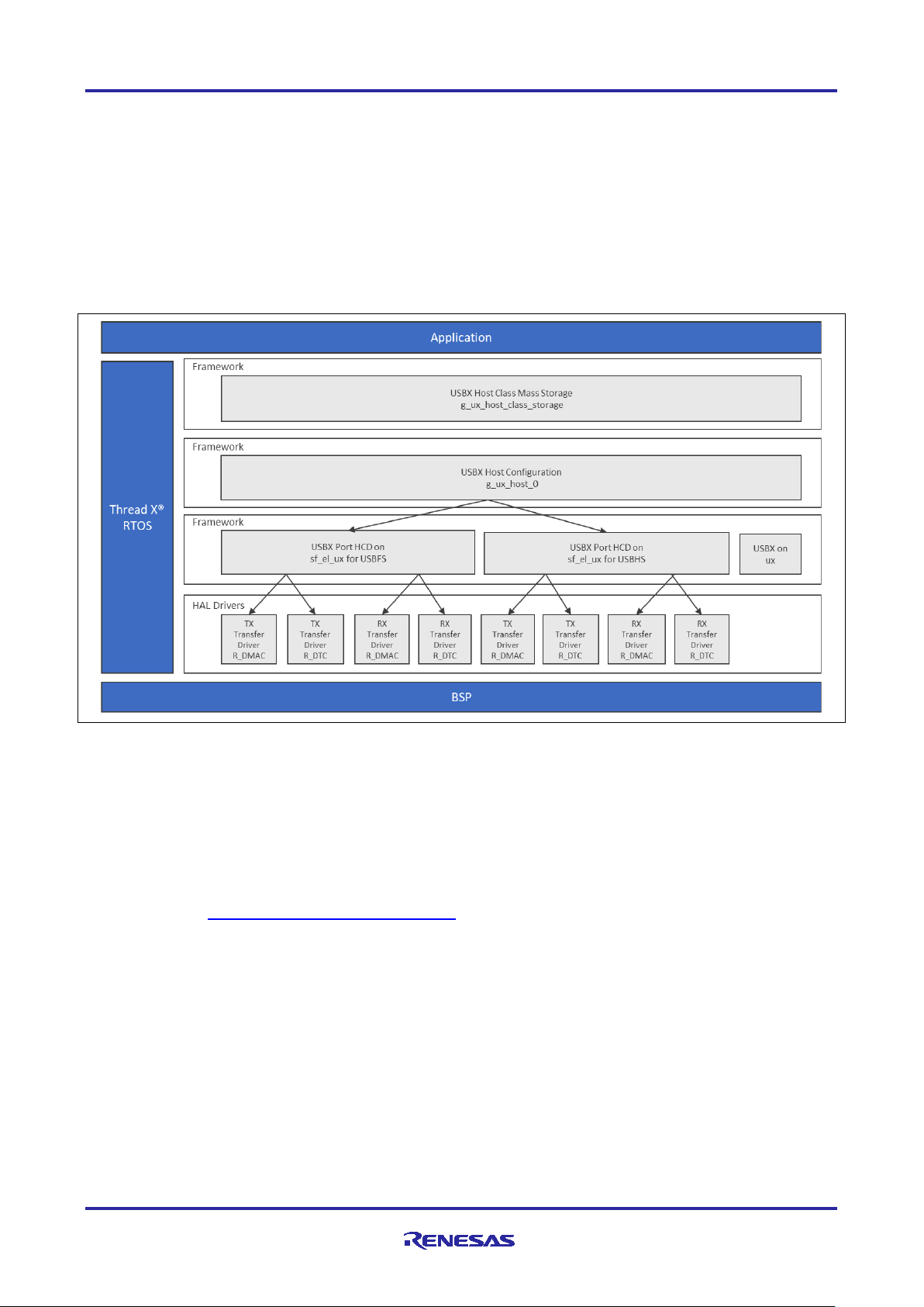
1. Features
• Host controller for USB 2.0 with support for:
Root Hub
Power Management
Endpoints
Transfers
• High-level APIs simplify storage operations
• Supports optional data transfers using MCU hardware for improved efficiency
Figure 1. USBX Host Class Mass Storage Module Organization, Options and Stack Implementations
2. Overview
The USBX Host Class Mass Storage module does not have a separate API available for user applications.
When a USB media is connected, it is attached to the FileX
Storage instance. The user application uses this FileX member to access files on the USB media. For FileX
APIs, refer to the FileX User Guide for the Renesas Synergy™ Platform for more details. This document is
part of an X-Ware™ Component Documents for Renesas Synergy™ zip file available from the Renesas
Synergy Gallery (www.renesas.com/synergy/software
®
member included in the USBX Host Class Mass
).
3. Operational Overview
Initialization of USBX Resources
The USBX has its own memory manager. The memory needs to be allocated to the USBX before the host or
device side of the USBX is initialized. The USBX memory manager can accommodate systems where
memory can be cached.
Definition of USB Host Controllers
It is required to define at least one USB host controller for the USBX to operate in host mode. The application
initialization file should contain this definition.
R11AN0173EU0104 Rev.1.04 Page 2 of 15
Sep.30.19
Page 3

Renesas Synergy™ Platform USBX™ Host Class Mass Storage Module Guide
Definition of Host Classes
It is required to define one or more host classes with the USBX. A USB class is required to drive a USB
device after the USB stack has configured the USB device. A USB class is very specific to the device. One
or more classes may be required to drive a USB device, depending on the number of interfaces contained in
the USB device descriptors.
USB Class Binding
When the device is configured, the topology manager will let the class manager continue the device
discovery by looking at the device-interface descriptors; a device can have one or more interface descriptors.
An interface represents a function in a device. A USB speaker has three interfaces; one for audio streaming,
one for audio control, and one to manage the various speaker buttons.
The class manager has two mechanisms to join the device interface(s) to one or more classes; it can either
use the combination of a PID/VID (product ID and vendor ID) found in the interface descriptor or the
combination of Class/Subclass/Protocol.
The PID/VID combination is valid for interfaces that cannot be driven by a generic class. The
Class/Subclass/Protocol combination is used by interfaces that belong to a USB-IF certified class such as a
printer, hub, storage, audio, or HID.
The class manager contains a list of registered classes from the initialization of the USBX. The class
manager will call each class one-at-a-time until one class agrees to manage the interface for that device;
each class can only manage one interface. (In the case of the USB audio speaker, the class manager will
call all the classes for each of the interfaces.)
Once a class accepts an interface, a new instance of that class is created. The class manager searches for
the default alternate setting for the interface. A device may have one or more alternate settings for each
interface; the alternate setting 0 will be the one used b y def ault unt il a class dec id es to change it.
For the default alternate setting, the class manager will mount all the endpoints contained in the alternate
setting. If the mounting of each endpoint is successful, the class manager will complete its job by returning to
the class that will finish the initialization of the interface.
3.1 Operational Notes and Limitations
3.1.1 Operational notes
• Use a class container for the USBX Host Class Mass Storage module obtained by auto-generated code
to get a mass storage instance.
• Pole the flag ux_host_class_storage_state in and make sure the status is live.
• Wait until the first media of the class container is attached.
• Access the file on the media with the FileX API.
3.1.2 Limitations
The module uses the interrupt of a USB controller; set the appropriate interrupt-priority level in the Synerg y
Configuration tool to ensure proper operation.
The module uses the interrupt of a transfer module (implemented as DMAC or DTC); set the appropriate
priority level in the Synergy Configuration tool. The level must be higher than a USB Controller to ensure
proper operation.
Refer to the most recent SSP Release Notes for any additional operational limitations for this module.
4. Including the USBX Host Class Mass Storage Module in an Application
This section describes how to include the USBX Host Class Mass Storage module in an application using the
SSP configurator.
Note: This section assumes you are familiar with creating a project, adding threads, adding a stack to a
thread, and configuring a block within the stack. If you are unfamiliar with any of these items, refer to
the first few chapters of the SSP User’s Manual to learn how to manage each of these important
To add the USBX Host Class Mass Storage module to an application, simply add it to a thread using the
stacks selection sequence given in the following table. (The default name for the USBX Host Class Mass
R11AN0173EU0104 Rev.1.04 Page 3 of 15
Sep.30.19
steps in creating SSP-based applications.
Page 4
Renesas Synergy™ Platform USBX™ Host Class Mass Storage Module Guide
Resource
ISDE Tab
Stacks Selection Sequence
g_ux_host_class_storage0 USBX
Threads
New Stack > X-Ware > USBX > Host >
Class Mass Storage
Storage is g_ux_host_class_storage0. This name can be changed in the associated Properties
window.)
Table 1. USBX Host Class Mass Storage Selection Sequence
Host Class Mass Storage
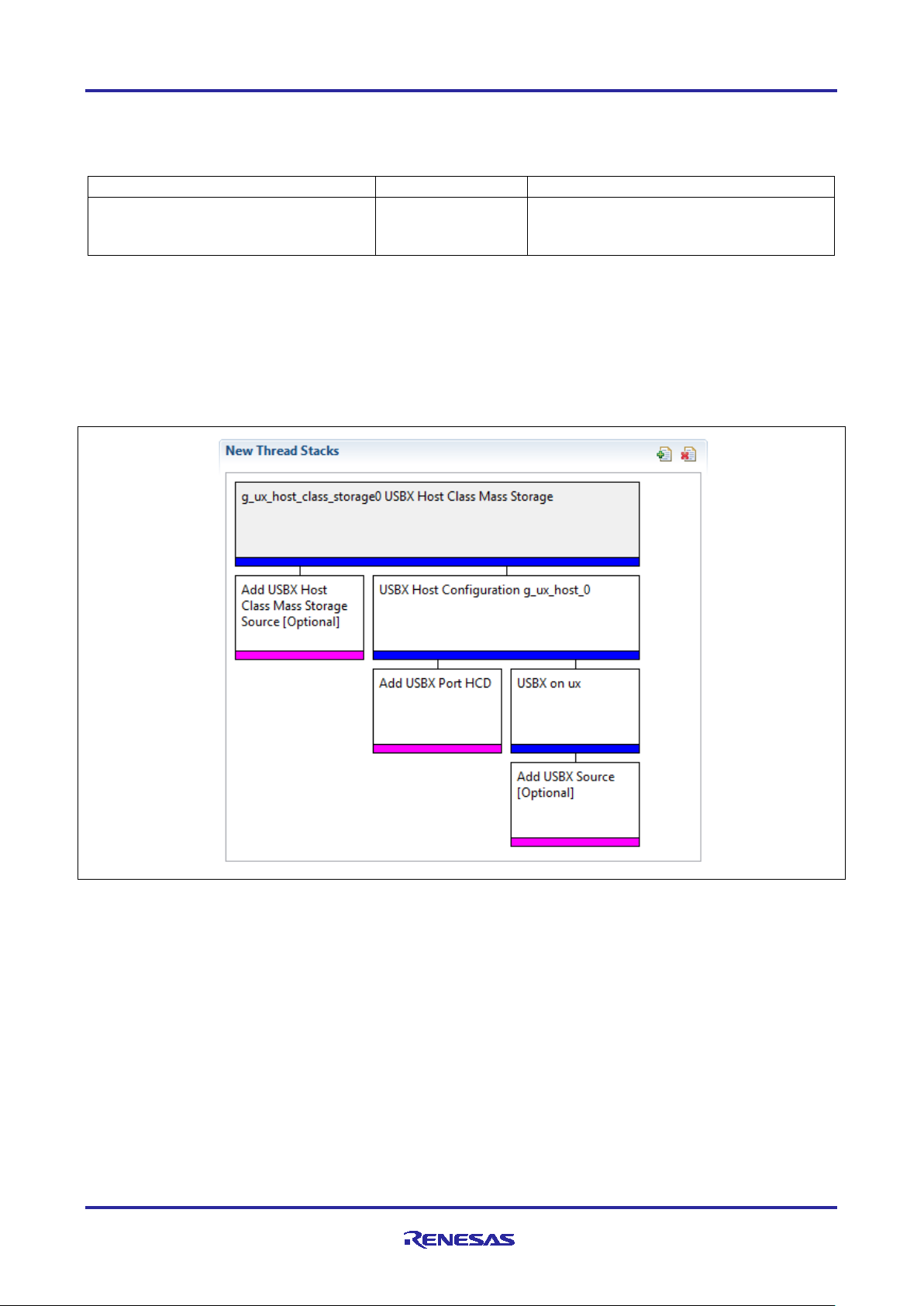
When the USBX Host Class Mass Storage is added to the thread stack as shown in the following figure, the
configurator automatically adds any need ed lo wer -level drivers. Any drivers that need additional
configuration inform ation will be box text hig hl ight ed in red. Modu les with a gray band are individual modules
that stand alone. Modules with a blue band are shared or common and need only be added once and can be
used by multiple stacks. Modules with a pink band can require the selection of lower-level drivers; these are
either optional or recommended. (This is indicated in the block with the inclusion of this text.) If the addition
of lower-level drivers is required, the module description will include Add in the text. Clicking on any pink
banded modules will bring up the New icon and then display the possible choices.
Classes > Mass Storage > USBX Host
Figure 2. USBX Host Class Mass Storage Module Stack
5. Configuring the Storage Module
The USBX Host Class Mass Storage module must be configured by you for the desired operation. The SSP
configuration window will a utomatically identify (by highlighting the block in red) any required configuration
selections, such as interrupts or operating modes, that must be configured for lower-level modules for
successful operation. Only those properties that can be changed without causing conflicts are available for
modification. Other properties are locked and are not available for changes and are identified with a lock
icon for the locked property in the Properties window in the ISDE. This approach simplifies the configuration
process and makes it much less error-prone than previous manual approaches to configuration. The
available configuration settings and defaults for all the user accessible properties are given in the properties
tab within the SSP Configurator and are shown in the following tables for easy reference.
One of the properties most often identified as requiring a change is the interrupt priority; this configuration
setting is available within the Properties window of the associated module. Simply select the indicated
module and then view the Properties window; the interrupt settings are often toward the bottom of the
properties list, so scroll down until they become available. Note that the interrupt priorities listed in the
R11AN0173EU0104 Rev.1.04 Page 4 of 15
Sep.30.19
Page 5
Renesas Synergy™ Platform USBX™ Host Class Mass Storage Module Guide
ISDE Property
Value
Description
Name
g_ux_host_class_storage0
Module name
ISDE Property
Value
Description
Name
g_ux_host0
Module name
ISDE Property
Value
Description
Full Speed Interrupt Priority
Priority 0 (highest), Priority 1:2,
Default: Disabled
Full speed interrupt priority
VBUSEN pin Signal Logic
Active Low, Active High
Default: Active High
VBUSEN pin signal logic
selection
Name
g_sf_el_ux_hcd_fs_0
Module name
USB Controller Selection
USBFS
USB controller selection
ISDE Property
Value
Description
High Speed Interrupt Priority
Priority 0 (highest), Priority 1:2,
not valid if using ThreadX, CM0+:
High speed interrupt priority
Properties window in the ISDE will include an indication as to the validity of the setting based on the targeted
MCU (CM4 or CM0+). This level of detail is not included in the following configuration properties tables but is
easily visible with the ISDE when configur i ng inter r upt prior ity levels.
Note: You may want to open your ISDE, create the module, and explore the property settings in parallel
with looking over the following configuration table settings. This will help orient you and can be a
useful hands-on approach to learning the ins and outs of developing with SSP.
Table 2. Configuration Settings for the USBX Host Class Mass Storage Module
Note: The example settings and defaults are for a project using the S7G2 Synergy Group. Other MCUs may
have different default values and available configuration settings.
In some cases, settings other than the defaults for a module can be desirable. For example, it might be
useful to select a different clock source than the default. The configurable properties for the lower-level stack
modules are given in the following sections for completeness and as a reference.
Note: Most of the property settings for lower-level modules are intuitive and usually can be determined by
inspection of the associated properties window from the SSP configurator.
5.1 Configuration Settings for Low-Level Modules
Typically, only a small number of settings must be modified from the default for lower-level modules as
indicated via the red text in the thread stack block. Notice that some of the configuration properties must be
set to a certain value for proper framework operation and will be locked to prevent user modification. The
following table identifies all the settings within the properties section for the module.
Table 3. Configuration Settings for the USBX Host Configuration
Table 4. Configuration Settings for the USBX Port HCD on sf_el_ux for USBFS
Priority 3 (CM4: valid, CM0+:
lowest- not valid if using ThreadX),
Priority 4:14 (CM4: valid, CM0+:
invalid), Priority 15 (CM4 lowest not valid if using ThreadX, C M0 +:
invalid)
Note: The example settings and defaults are for a project using the S7 Synergy MCU Group. Other MCUs
may have different default values and available configuration settings.
Table 5. Configuration Settings for the USBX HCD on sf_el_ux for USBHS
selection
R11AN0173EU0104 Rev.1.04 Page 5 of 15
Sep.30.19
Priority 3 (CM4: valid, CM0+:
lowest- not valid if using ThreadX),
Priority 4:14 (CM4: valid, CM0+:
invalid), Priority 15 (CM4 lowest -
selection
Page 6

Renesas Synergy™ Platform USBX™ Host Class Mass Storage Module Guide
ISDE Property
Value
Description
invalid)
FIFO size for Bulk Pipes
512, 1024, 1536, 2048 bytes
FIFO size for bulk pipes
VBUSEN pin Signal Logic
Active Low, Active High
VBUSEN pin signal logic
Name
g_sf_el_ux_hcd_hs_0
Module name
USB Controller Selection
USBHS
USB controller selection
ISDE Property
Value
Description
USBX Pool Memory Name
g_ux_pool_memory
USBX pool memory name
USBX Pool Memory Size
18432
USBX pool memory size
selection.
User Callback for Host Event
NULL
Callback name
ISDE Property
Value
Description
Parameter Checking
BSP, Enabled, Disabled
Selects if code for parameter
Name
g_transfer0
Module name
Channel
0
Channel number
Mode
Block
Mode selection
Transfer Size
1 Byte
Transfer size selection
Destination Address Mode
Incremented
Destination address mode
selection
Source Address Mode
Fixed
Source address mode selection
Repeat Area (Unused in Normal
Mode
Source
Repeat area selection
Destination Pointer
NULL
Destination pointer selection
Source Pointer
NULL
Source pointer selection
Number of Transfers
0
Number of transfers selection
Number of Blocks (Valid only in
Block Mode)
0
Number of blocks selection
Activation Source (Must enabl e
Software Activation
Activation source selection
Auto Enable
FALSE
Auto enable selection
Callback (Only valid with
NULL
Callback selection
Default: Disabled
Default: 512 bytes
Default: Active High
Note: The example settings and defaults are for a project using the Synergy S7 MCU Group. Other MCUs
may have different default values and available configuration settings.
Table 6. Configuration Settings for USBX on ux
Notifications (Only valid for USB
Host)
Note: The example settings and defaults are for a project using the S7 Synergy MCU Family. Other MCUs
may have different default values and available configuration settings.
Table 7. Configuration for RX Transfer Driver on r_dmac
selection
selection
selection.
IRQ)
Software start)
R11AN0173EU0104 Rev.1.04 Page 6 of 15
Sep.30.19
(Default: BSP)
checking is to be included in the
build
Page 7

Renesas Synergy™ Platform USBX™ Host Class Mass Storage Module Guide
ISDE Property
Value
Description
Interrupt Priority
Priority 0 (highest),
(Default: Disabled)
Interrupt priority selection
ISDE Property
Value
Description
Parameter Checking
BSP, Enabled, Disabled
Selects if code for parameter checking
Name
g_transfer0
Module name
Channel
0
Channel number
Mode
Block
Mode selection
Transfer Size
1 Byte
Transfer size selection
Destination Address
Mode
Incremented
Destination address mode selection
Source Address Mode
Fixed
Source address mode selection
Repeat Area (Unused
Source
Repeat area selection
Destination Pointer
NULL
Destination pointer selection
Source Pointer
NULL
Source pointer selection
Number of Transfers
0
Number of transfers selection
Number of Blocks
Mode)
0
Number of blocks selection
Activation Source
Software Activation
Activation source selection
Auto Enable
FALSE
Auto enable selection
Callback (Only valid
NULL
Callback selection
Interrupt Priority
Priority 0 (highest),
(Default: Disabled)
Interrupt priority selection
1,2,3,4,5,6,7,8,9,10,11,12,13,14,15
(lowest, not valid if using Thread
X), Disabled
Note: The above setting examples and defaults are for a project using the S7G2 Synergy MCU. Other
MCUs may have different default values and available configuration settings.
Table 8. Configuration for TX Transfer Driver on r_dmac
in Normal Mode
(Valid only in Block
(Must enable IRQ)
(Default: BSP)
is to be included in the build
with Software start)
Note: The above setting examples and defaults are for a project using the S7G2 Synergy MCU. Other
MCUs may have different default values and available configuration settings.
5.2 Clock configuration
The USB peripheral module uses UCLK as its clock source. The UCLK should be configured for 48 MHz
operation and can be checked in the Clocks tab of the SSP conf ig urat ion win do w.
5.3 Pin configuration
The USB peripheral module uses pins on the MCU to communicate to external devices. I/O pins must be
selected and configured as required by the external device. The following tables illustrate the method for
selecting the pins within the SSP configuration window and the subsequent table illustrates an example
selection for USB pins.
R11AN0173EU0104 Rev.1.04 Page 7 of 15
Sep.30.19
1,2,3,4,5,6,7,8,9,10,11,12,13,14,15
(lowest, not valid if using Thread
X), Disabled
Page 8

Renesas Synergy™ Platform USBX™ Host Class Mass Storage Module Guide
Resource
ISDE Tab
Pin selection Sequence
USBFS
Pins
Select Peripherals > Connectivity: USBFS> USBFS0
USBHS
Pins
Select Peripherals > Connectivity: USBHS> USBHS0
Property
Value
Description
Operation Mode
Disabled, Custom, Device,
Select Device as the Operation Mode
USBDP
USBDP
USBDP Pin
USBDM
USBDM
USBDM Pin
OVRCURB
None
OVRCURB Pin
OVRCURA
None
OVRCURA Pin
VBUSEN
None
VBUSEN Pin
VBUS
None, P407
VBUS Pin
EXICEN
None
EXICEN Pin
ID
None
ID Pin
VCCUSB
VCCUSB
VCCUSB Pin
VSSUSB
VSSUSB
VSSUSB Pin
Property
Value
Description
Operation Mode
Disabled, Custom, Device,
(Default: Disabled)
Select Device as the Operation Mode
USBHSDP
USBHSDP
USBHSDP Pin
USBHSDM
USBHSDM
USBHSDM Pin
OVRCURB
None
OVRCURB Pin
OVRCURA
None
OVRCURA Pin
VBUSEN
None
VBUSEN Pin
VBUS
None
VBUS Pin
EXICEN
None
EXICEN Pin
ID
None
ID Pin
USBHSRREF
USBHSRREF
USBHSRREF Pin
AVCCUSBHS
AVCCUSBHS
AVCCUSBHS Pin
AVSSUSBHS
AVSSUSBHS
AVSSUSBHS Pin
PVSSUSBHS
PVSSUSBHS
PVSSUSBHS Pin
Note: The operation mode selection determines what peripheral signals are available and thus what MCU
Table 9. Pin Selection Sequence for USBFS and USBHS
Note: The selection sequence assumes USBFS0 or USBHS0 are the desired hardware target for the driver.
Table 10. Pin Configuration Settings for the USBFS
pins are required.
Host, OTG
(Default: Disabled)
(Default: P407)
Note: The example settings are for a project using the S7G2 Synergy MCU G roup and the SK-S7G2 Kit.
Other Synergy Kits and other Synergy MCUs may have different available pin configuration settings.
Table 11. Pin Configuration Settings for the USBHS
Host, OTG
Note: The example settings are for a project using the S7G2 Synergy MCU Group and the SK-S7G2 Kit.
Other Synergy Kits and other Synergy MCUs may have different available pin configuration settings.
6. Using the USBX Host Class Mass Storage Module in an Application
The configurator generates processing to create and register the USBX Host Class Mass Storage module.
File access must be done after the device is connected. Because FileX is used, checking [Express Logic]
[fx] on the Components tab of the configurator is necessary.
R11AN0173EU0104 Rev.1.04 Page 8 of 15
Sep.30.19
Page 9

Renesas Synergy™ Platform USBX™ Host Class Mass Storage Module Guide
The typical steps in using the USBX Host Class Mass Storage module in an application are:
1. Get the first instance of the connected device with ux_host_stack_class_instance_get API.
2. Wait until successful.
3. Wait for the device status to become live.
4. Wait for media to be mounted.
5. Access the file on the media with the FileX API.
These common steps are illustrated in a typical operational flow diagram in the following figure:
Figure 3. Flow Diagram of a Typical USBX Host Class Mass Stor age Module Application
7. Application Project
The application project associated with this module guide demonstrates the mentioned steps in a full design.
The project can be found using the link provided in the References section at the end of this document. You
may want to import and open the application project within the ISDE and view the configuration settings for
the USBX Host Class Mass Storage module. You can also read over the code (in usb_thread_entry.c)
used to illustrate the USBX Host Class Mass Storage module APIs in a complete design.
The application project demonstrates the typical use of the USBX Host Class Mass Storage module APIs.
The application project main thread entry waits for the connection from the callback function, reads the
firstdir\counter.txt file in the USB memory, and updates the described number. If firstdir does
not exist, the directory information is ignored. If this file does not exist, create a file. After updating the file,
the application waits until the USB memory is unplugged. The application uses LED2, LED1, and L ED0 in
sequence to provide status of the application. When all three or two LEDS (depending upon eval uat ion
board) lights up, it indicates that the operation is complete and you can disconnect the attached mass
storage device. The application uses SEMI-HOSTING feature; it displays relevant messages and errors to
the user.
The user-callback function obtains a pointer of FileX by using
ux_system_host_storage_fx_media_get and notifies the main thread of the plugged or unplugged
state. The following table identifies the target versions for the associated software and hardware used by the
application project.
R11AN0173EU0104 Rev.1.04 Page 9 of 15
Sep.30.19
Page 10

Renesas Synergy™ Platform USBX™ Host Class Mass Storage Module Guide
Resource
Revision
Description
e2 studio
7.3.0 or later
Integrated Solution Development Environment
SSP
1.6.0 or later
Synergy Software Platform
IAR EW for Renesas Synergy
8.23.3 or later
IAR Embedded Workbench® for Renesas Synergy™
SSC
7.3.0 or later
Synergy Standalone Configurator
SK-S7G2
v3.0 to v3.3
Starter Kit
Table 12. Software and Hardware Resources Used by the Application Project
A simple flow diagram of the application project is given in the following figure.
Figure 4. USBX Host Class Mass Storage Module Application Project Fl ow Dia g ram
The usb_thread_entry.c file is located in the project once it has been imported into the ISDE. You can
open this file within the ISDE and follow along with the following description to help identify key uses of APIs.
The first section of usb_thread_entry.c is a header file for the user thread. The following section is a
callback function where USB memory is connected or disconnected. The last section is the user thread that
reads from and writes to the USB memory; when connected to USB memory,
usb_host_plug_event_notification is called. This callback function determines the connected device
from the argument, saves the pointer of the FileX instance, and notifies the user thread. This callback
function is also called when the USB memory was unplugged. The user thread receives notification from the
callback function and starts access to the USB memory. The user thread gets the volume name of the media
and sets the default directory to firstdir, open counter.txt, update the first written character, and write
it again. Close the media and wait for the USB memory to be unplugged.
The application implements primary error handling. On detection of any error, the application displays the
error on the Renesas virtual debugging console and halts the thread execution.
A few key properties are configured in this application project to support the required operations and the
physical properties of the target board and MCU. The properties with the values set for this specific project
are listed in the following table; you can also open the application project and view these settings in the
Properties window as a hands-on exercise.
R11AN0173EU0104 Rev.1.04 Page 10 of 15
Sep.30.19
Page 11

Renesas Synergy™ Platform USBX™ Host Class Mass Storage Module Guide
ISDE Property
Value Set
USBX Port HCD on sf_el_ux for USBHS High Speed Interrupt Priority
Priority 3
VBUSEN pin Signal Logic
Active Low
USBX on ux USBX Po o l M emory Size
63488
User Callback for Host Event Notification (Only valid for USB Host)
usb_host_plug_event_notification
ISDE Property
Value
Description
Parameter Checking
BSP, Enabled, Disabled
(Default: BSP)
Selects if code for parameter checking is
to be included in the build
Name
g_transfer0
Module name
Channel
0
Channel number
Mode
Block
Mode selection
Transfer Size
1 Byte
Transfer size selection
Destination Address Mode
Incremented
Destination address mode selection
Source Address Mode
Fixed
Source address mode selection
Repeat Area (Unused in Normal
Source
Repeat area selection
Destination Pointer
NULL
Destination pointer selection
Source Pointer
NULL
Source pointer selection
Number of Transfers
0
Number of transfers selection
Number of Blocks (Valid only in
0
Number of blocks selection
Activation Source (Must enabl e
IRQ)
Software Activation
Activation source selection
Auto Enable
FALSE
Auto enable selection
Callback (Only valid with
Software start)
NULL
Callback selection
Interrupt Priority
Priority 2
Interrupt priority selection
ISDE Property
Value
Description
Parameter Checking
BSP, Enabled, Disabled
(Default: BSP)
Selects if code for parameter checking
is to be included in the build
Name
g_transfer1
Module name
Channel
1
Channel number
Mode
Block
Mode selection
Transfer Size
1 Byte
Transfer size selection
Destination Address Mode
Incremented
Destination address mode selection
Source Address Mode
Fixed
Source address mode selection
Repeat Area (Unused in Normal
Mode
Source
Repeat area selection
Destination Pointer
NULL
Destination pointer selection
Source Pointer
NULL
Source pointer selection
Number of Transfers
0
Number of transfers selection
Number of Blocks (Valid only in
Block Mode)
0
Number of blocks selection
Activation Source (Must enabl e
IRQ)
Software Activation
Activation source selection
Table 13. USBX Host Class Mass Storage Module Configuration Settings for the Application Project
Table 14. Configuration for RX Transfer Driver on r_dmac for Application Project
Mode)
Block Mode)
Note: The above setting examples and defaults are for a project using the S7G2 Synergy MCU. Other
MCUs may have different default values and available configuration settings.
Table 15. Configuration for TX Transfer Driver on r_dmac for Application Project
R11AN0173EU0104 Rev.1.04 Page 11 of 15
Sep.30.19
Page 12

Renesas Synergy™ Platform USBX™ Host Class Mass Storage Module Guide
ISDE Property
Value
Description
Auto Enable
FALSE
Auto enable selection
Callback (Only valid with
NULL
Callback selection
Interrupt Priority
Priority 2
Interrupt priority selection
Software start)
Note: The above setting examples and defaults are for a project using the S7G2 Synergy MCU. Other
MCUs may have different default values and available configuration settings.
8. Customizing for a Target Application
Some configuration settings will normally be changed by the user from those shown in the application
project. For example, you can also add a data-transfer module for data transfer of USBX Port HCD. This
data-transfer module can be added simply by clicking on the box for TX or RX displayed under the USBX
Port HCD box of the configurator.
9. Running the Application Project
To run the USBX Host Class Mass Storage module application project and to see it executed on a target kit,
you can simply import it into your ISDE, compile, and run debug. Refer to the Renesas Synergy™ Project
Import Guide (r11an0023eu0121-synergy-ssp-import-guide) included in this pack age for instructions on
importing the project into e
building/running the application.
To implement the USBX Host Class Mass Storage module application in a new project, follow the steps for
defining, configuring, auto-generating files, adding code, compiling, and debugging on the target kit.
Following these steps is a hands-on approach that can help make the development process with SSP more
practical.
2
studio or IAR Embedded Workbench® for Renesas Synergy™ and
Note: The following steps are described in sufficient detail for someone experienced with the basic flow
through the Synergy development process. If these steps are not familiar, refer to the first few
To create and run the USBX Host Class Mass Storage application project, simply follow these steps:
1. Create a new Renesas Synergy project for the S7G2-SK called USBX_Mass_Storage_Host.
2. Select the Threads tab.
3. Add the usb_thread to Threads.
4. Add the EventFlags on USB Thread Objects.
5. Add the FileX on USBX Mass Storage module to the USB Thread Stacks.
6. Click the USBX on ux box on the USB Thread Stacks.
7. Change the USBX Pool Memory Size to 63488 on property window.
8. Change the User Callback for Host Event Notification (Only valid for USB Host) to
9. Click the Add USBX Port HCD box and select the USBX Port HCD on sf_el_ux for USBHS.
10. Change the High Speed Interrupt Priority to Priority 3 on the propert y windo w.
11. Change the VBUSEN pin Signal Logic to Active Low on the pr o per ty window.
12. Click on the Generate Project Content button.
13. Add the code from the supplied project file usb_thread_entry.c or copy over the generated
14. Connect to the host PC via a micro USB cable to J19 on SK-S7G2. Note: If S3A7 board is used, switch
15. Start to debug the application.
16. Insert the USB memory into J6 connector on SK-S7G2.
17. Wait for the three LEDs on SK-S7G2 to light up.
18. Remove the USB memory from SK-S7G2.
19. The written file to the USB memory can be seen on the host PC.
chapters of the SSP Us er ’s Manual for a description of how to accomplish these steps.
Name: USB Plug Event Flags
Symbol: g_usb_plug_events
usb_host_plug_event_notification on the property window.
usb_thread_entry.c file also build the project.
S6 USBF should be set to off state.
R11AN0173EU0104 Rev.1.04 Page 12 of 15
Sep.30.19
Page 13

Renesas Synergy™ Platform USBX™ Host Class Mass Storage Module Guide
Note: When testing the application on DK-S3A7, make sure that the switch S6 (USBF) is turned off.
Figure 5. Example Initial File by USBX Host Class Mass Storage Module Application Project
10. Conclusion
This module guide has provided all the background information needed to select, add, configure, and use the
module in an example project. Many of these steps were time consuming and error-prone activities in
previous generations of embedded systems. The Renesas Synergy
time consuming and removes the common errors, like conflicting configuration settings or incorrect selection
of lower-level drivers. The use of high-level APIs as dem ons trat ed in the applic ati on projec t illus trate
additional development time savings by allowing work to begin at a high level and avoiding the time required
in older development environments to use or in some cases, create, lower-level d rivers .
™
Platform makes these steps much less
11. Next Steps
After you have mastered a simple USBX Host Class Mass Storage module project you may want to review a
more complex example. Other application projects and application notes that demonstrate USBX Host Class
Mass Storage use can be found as described in the References section below.
12. Reference Information
SSP User’s Manual: Available in html format in the SSP distribution package and as a pdf from the Renesas
Synergy Gallery.
Links to all the most up-to-date USBX Host Class Mass Storage module reference materials and resources
are available on the Renesas Synergy Knowledge Base:
support.renesas.com/knowledgeBase/16977576.
https://en-
R11AN0173EU0104 Rev.1.04 Page 13 of 15
Sep.30.19
Page 14

Renesas Synergy™ Platform USBX™ Host Class Mass Storage Module Guide
Website and Support
Visit the following vanity URLs to learn about key elements of the Synergy Platform, download components
and related documentation, and get support.
Synergy Software www.renesas.com/synergy/software
Synergy Software Package www.renesas.com/synergy/ssp
Software add-ons www.renesas.com/synergy/addons
Software glossary www.renesas.com/synergy/softwareglossary
Development tools www.renesas.com/synergy/tools
Synergy Hardware www.renesas.com/synergy/hardware
Microcontrollers www.renesas.com/synergy/mcus
MCU glossary www.renesas.com/synergy/mcuglossary
Parametric search www.renesas.com/synergy/parametric
Kits www.renesas.com/synergy/kits
Synergy Solutions Gallery www.renesas.com/synergy/solutionsgallery
Partner projects www.renesas.com/synergy/partnerprojects
Application projects www.renesas.com/synergy/applicationprojects
Self-service support resources:
Documentation www.renesas.com/synergy/docs
Knowledgebase www.renesas.com/synergy/knowledgebase
Forums www.renesas.com/synergy/forum
Training www.renesas.com/synergy/training
Videos www.renesas.com/synergy/videos
Chat and web ticket www.renesas.com/synergy/resourcelibrary
R11AN0173EU0104 Rev.1.04 Page 14 of 15
Sep.30.19
Page 15

Renesas Synergy™ Platform USBX™ Host Class Mass Storage Module Guide
Rev.
Date
Description
Page
Summary
1.00
Jul.31.17
-
Initial release
1.01
Nov.27.17
-
Update to Hardware and Software Resources Table
Editing and release
1.02
Jan.31.19
-
Minor updates to application project settings
1.03
Apr.26.19
-
Updated for SSP v1.6.0
1.04
Sep.30.19
-
Updated for SSP v1.7.0
Revision History
R11AN0173EU0104 Rev.1.04 Page 15 of 15
Sep.30.19
Page 16

Corporate Headquarters
Contact information
www.renesas.com
Trademarks
of their respective owners.
Notice
1. Descriptions of circuits, software and other related information in this document are provided only to illustrate the operation of semiconductor products
and application examples. You are fully responsible for the incorporation or any other use of the circuits, software, and information in the design of your
product or system. Renesas Electronics disclaims any and all liability for any losses and damages incurred by you or third parties arising from the use
of these circuits, software, or information.
2. Renesas Electronics hereby expressly disclaims any warranties against and liability for infringement or any other claims involving patents, copyrights,
or other intellectual pro pe rt y rig hts of th i rd par ties, by or arising from the use of Renesas Electronics products or technical information described in this
document, including but not limited to, the product data, drawings, charts, programs, algorithms, and application examples.
3. No license, express, implied or otherwise, is granted hereby under any patents, copyrights or other intellectual property rights of Renesas Electronics
or others.
4. You shall not alter, modify, copy, or reverse engineer any Renesas Electronics product, whether in whole or in part. Renesas Electronics disclaims any
and all liability for any losses or damages incurred by you or third parties arising from such alteration, modification, copying or reverse engineering.
5. Renesas Electronics products are classified according to the following two quality grades: “Standard” and “High Quality”. The intended applications for
each Renesas Electronics product depends on the product’s quality grade, as indicated below.
"Standard": Computers; office equipment; communications equipment; test and measurement eq uipm e nt ; audi o and visu al equi p m ent ; hom e
"High Quality": Transportation equipment (automobiles, trains, ships, etc.); traffic control (traffic lights); large-scale communication equipment; key
Unless expressly designated as a high reliability product or a product for harsh environments in a Renesas Electronics data sheet or other Renesas
Electronics document, Renesas Electronics products are not intended or authorized for use in products or systems that may pose a direct threat to
human life or bodily injury (artificial life support devices or systems; surgical implantations; etc.), or may cause serious propert y damage (space
system; undersea repeaters; nuclear power control systems; aircraft control systems; key plant systems; military equipment; etc.). Renesas Electronics
disclaims any and all liability for any damages or losses incurred by you or any third parties arising from the use of any Renesas Electronics product
that is inconsistent with any Renesas Electronics data sheet, user’s manual or other Renesas Electronics document.
6. When using Renesas Electronics products, refer to the latest product information (data sheets, user’s manuals, application notes, “General Notes for
Handling and Using Semiconductor Devices” in the reliability handbook, etc.), and ensure that usage conditions are within the ranges specified by
Renesas Electronics with respect to maximum ratings, operating power supply voltage range, heat dissipation characteristics, installation, etc. Renesas
Electronics disclaims any and all liability for any malfunctions, failure or accident arising out of the use of Renesas Electronics products outside of suc h
specified ranges.
7. Although Renesas Electronics endeavors to improve the quality and reliability of Renesas Electronics products, semiconductor products have specific
characteristics, such as the occurrence of failure at a certain rate and malfunctions under certain use conditions. Unless designated as a high reliability
product or a product for harsh environments in a Renesas Electronics data sheet or other Renesas Electronics document, Renesas Electronics
products are not subject to radiation resistance design. You are responsible for implementing safety measures to guard against the possibility of bodily
injury, injury or damage caused by fire, and/or danger to the public in the event of a failure or malfunction of Renesas Electronics products, such as
safety design for hardware and software, including but not limited to redundancy, fire control and malfunction prevention, appropriate treatment for
aging degradation or any other appropriate measures. Because the evaluation of microcomputer software alone is very difficult and impractical, you are
responsible for evaluating the safety of the final products or systems manufactured by you.
8. Please contact a Renesas Electronics sales office for details as to environmental matters such as the environmental compatibility of each Renesas
Electronics product. You are responsible for carefully and sufficiently investigating applicable laws and regulations that regulate the inclusion or use of
controlled substances, including without limitation, the EU RoHS Directive, and using Renesas Electronics products in compliance with all these
applicable laws and regulations. Renesas Electronics disclaims any and all liability for damages or losses occurring as a resul t of your no nc om pliance
with applicable laws and regulations.
9. Renesas Electronics products and technologies shall not be used for or incorporated into any products or systems whose manufacture, use, or sale is
prohibited under any applicable domestic or foreign laws or regulations. You shall comply with any applicable export control laws and regulations
promulgated and administered by the governments of any countries asserting jurisdiction over the parties or transactions.
10. It is the responsibility of the buyer or distributor of Renesas Electronics products, or any other party who distributes, disposes of, or otherwise sells or
transfers the product to a third party, to notify such third party in advance of the contents and conditions set forth in this document.
11. This document shall not be reprinted, reproduced or duplicated in any form, in whole or in part, without prior written consent of Renesas Electronics.
12. Please contact a Renesas Electronics sales office if you have any questions regarding the information contained in this document or Renesas
Electronics products.
(Note1) “Renesas Electronics” as used in this document means Renesas Electronics Corporation and also includes its directly or indirectl y co ntr oll ed
(Note2) “Renesas Electronics product(s)” means any product developed or manufactured by or for Renesas Electronics.
subsidiaries.
electronic appliances; machine tools; personal electronic equipment; industrial robots; etc.
financial terminal systems; safety control equipment; etc.
(Rev.4.0-1 Novembe r 201 7)
TOYOSU FORESIA, 3-2-24 Toyosu,
Koto-ku, Tokyo 135-0061, Japan
Renesas and the Renesas logo are trademarks of Renesas Electronics
Corporation. All trademarks and registered trademarks are the property
For further information on a product, technology, the most up-to-date
version of a document, or your ne are s t sales office, please visit:
www.renesas.com/contact/
.
© 2019 Renesas Electronics Corporation. All rights reserved.
 Loading...