

Page 1

All information contained in these materials, including products and product specifications,
website (http://www.renesas.com).
TPS-1
: Hardware
Rev.1.07 Jul 2018
RENESAS ASSP
Ethernet Controller
User’s Manual
www.renesas.com
User’s Manual
for PROFINET IO Devices
represents information on the product at the time of publication and is subject to change by
Renesas Electronics Corp. without notice. Please review the latest information published by
Renesas Electronics Corp. through various means, including the Renesas Electronics Corp.
Page 2

Notice
on of
1. Descriptions of circuits, software and other related information in this document are provided only to illustrate the operati
semiconductor products and application examples. You are fully responsible for the incorporation or any other use of the circuits,
software, and i nformation i n the desi gn of your produc t or syste m. Renesa s Electr onics discla ims any and al l liabilit y for any loss es and
damages incurred by you or third parti es arising from the use of these circuits, software, or infor ma tion.
2. Renesas Elec tronics hereby expressly disclai ms any warranties against and liabi lity for infringeme nt or any other claims involving patents,
copyrights, or other intellectual prop erty rights of third part ies, by or arising from the use of Renesas Electronics pr oducts or technical
information described in this document, including but not limited to, the product data, drawings, charts, programs, algorithms, and
application examples.
3. No license, expr ess, impli ed or otherwi se, is gra nted hereb y under an y patents , copyright s or other intell ectual prop erty rights of Renesas
Electronics or others.
4. You shall not alter , modify, copy, or revers e engineer any Renes as Electr onics product , whether in whole or in part. Renesas Electronics
disclaims any and all liability for any losses or damages incurred by you or third parties arising from such alteration, modification,
copying or reverse engineering.
5. Renesas Electroni cs products are cla ssified accordi ng to the following two qua lity grades: “Sta ndard” and “High Quali ty”. The intended
applications for each Renesas Electronics product depends on the product’s quality grade, a s indicated below.
“Standard”: Computers; office equipment; communications equipment; test and measurement equi pment; audio and visual equipment;
home electronic appliances; machine tools; personal electronic eq uipment; industria l robots; etc.
“High Quality”: Transportation equipment (automobiles, trains, ships, etc.); traffic control (traffic lights); large-scale communication
equipment; key financial terminal systems; safety control equipment; etc.
Unless expressl y designated a s a high reli abilit y product or a product for ha rsh environ ments in a Renes as Elec tronics data sheet or ot her
Renesas Electr onic s docum ent, Ren esa s El ectr onic s pr oduc ts a re not i ntended or a uthor i z ed for us e in produc t s or systems tha t may pose a
direct threat to huma n life or bodily injury (ar tificial life supp ort devices or systems; s urgical implantations ; etc.), or may cause ser ious
property damage (s pace system; unders ea repeaters ; nuclear power cont rol systems; a ircraft control systems; key pla nt systems; milit ary
equipment; etc. ). Renesa s El ectroni cs dis claims a ny and al l liab ilit y for any damages or los ses i ncurred b y you or any thi rd parties arising
from the use of any Renes as Electronics product that is inconsistent with any Renesa s Electronics data sheet, us er’s manual or other
Renesas Electronics document.
6. When using Renesas Elect roni cs product s, r efer to t he lates t product informa tion ( data sheet s, user ’s manu als, applica tion not es, “Genera l
Notes for Handling a nd Using Semic onductor Devices ” in the relia bility handbook, etc.), and ens ure that usage c onditions are w ithin the
ranges specified by Renesas Electronics with respect to maximum ratings, operating power supply voltage range, heat dissipation
characterist ics, insta llation, etc. Renesa s Electr onics dis claims any and a ll liabi lity for any ma lfunct ions, fa ilure or acc ident aris ing out of
the use of Renesas Electronics products outside of such specified ranges.
7. Although Renesa s Electroni cs endeavors to imp rove the qual ity and relia bility of Renes as Electroni cs products, semiconductor products
have specific cha racteristics, such as the occurrenc e of failure at a certain rate and malf unctions under certain use conditi ons. Unless
designated as a high reliability product or a product for harsh environments in a Renesas Electronics data sheet or other Renesas
Electronics document, Renesa s Elect ronics produc ts are not s ubject t o radiation res istance des ign. You are r esponsib le for implement ing
safety measures to gua rd aga ins t the pos sibi lity of b odil y injur y, injur y or da mage c aus ed by fir e, a nd/or d anger t o the p ublic in the e vent
of a failure or malf unction of Renesas Elec tronics pr oducts, s uch as safety design for ha rdware a nd software, including b ut not limited t o
redundancy, fire control and malfunction prevention, appropriate treatment for aging degradation or any other appropriate measures.
Because the e valuat ion of mic roc omputer s oft ware a lone is very dif fi cult and imp ract ical, you are res pons ibl e for eval uat ing the s afet y of
the final products or systems manufactured by you.
8. Please contact a Renesas El ectronics sa les office f or details as to environmenta l matters such as the en vironmental compatibility of each
Renesas Elec tronic s produc t. Y ou are r esp onsibl e for c aref ully and s uff icient ly inves ti gati ng appl icab le laws and r egulat ions that regula te
the inclusion or use of controlled substances, including without limitation, the EU RoHS Directive, and using Renesas Electronics
products in compl iance with all these applicab le laws and regul ations. Renesa s Electr onics disclai ms any and all liab ility for damages or
losses occurring as a result of your noncompliance wit h applicable laws and regulations.
9. Renesas Electr oni cs pr oduc ts and t echnol ogi es s ha ll not be us ed f or or incorp or ated i nt o any pr oduc ts or s ystems whos e manuf act ur e, us e,
or sale is pr ohibited under a ny applica ble domestic or foreign laws or regulati ons. You shall comply with an y applicabl e export contr ol
laws and regulations promulgated and administered by the governments of any countries asserting jurisdiction over the parties or
transactions.
10. It is the respons ibility of the buyer or distributor of Renesas Electronics products, or any other party who distr ibutes, disposes of, or
otherwise sell s or tr ansf er s the p r oduct to a thi rd pa r ty, t o noti f y such t hir d p ar ty in a dvanc e of the c ont ent s a nd condi t ions s et f orth i n t his
document.
11. This document sha ll not be repri nted, rep roduced or dup licated i n any form, in whole or in part, wit hout prior wr itten consent of Renesa s
Electronics.
12. Please contact a Renesas Electronics sales of fice if you have an y questions r egarding the information conta ined in this document or
Renesas Electronics products.
(Note 1) “Renesas Elect ronics” as used in t his document m eans Renesas Electronics Corporation a nd also incl udes its direc tly or indirect ly
controlled subsidiaries.
(Note 2) “Renesas Electronics product(s)” means any product developed or manufactured by or for Renesas Electronics.
(Rev.4.0-1 November 2017)
Page 3

1. Handling of Unused Pins
Handle unused pins in accord with the directions given under Handling of Unused Pins in the manual.
- The input pins of CMOS products are generally in the high-impedance state. In operation with an unused pin in
the open-circuit state, extra electromagnetic noise is induced in the vicinity of LSI, associated shoot-through
current flows internally, and malfunctions occur due to the false recognition of the pin state as an input signal
become possible. Unused pins should be handled as described under Handling of Unused Pins in the manual.
2. Processing at Power-on
The state of the product is undefined at the moment when power is supplied.
- The states of internal circuits in the LSI are indeterminate and the states of register settings and pins are
undefined at the moment when power is supplied.
In a finished product where the reset signal is applied to the external reset pin, the states of pins are not
guaranteed from the moment when power is supplied until the reset process is completed.
In a similar way, the states of pins in a product that is reset by an on-chip power-on reset function are not
guaranteed from the moment when power is supplied until the power reaches the level at which resetting has
been specified.
3. Prohibition of Access to Reserved Addresses
Access to reserved addresses is prohibited.
- The reserved addresses are provided for the possible future expansion of functions. Do not access these
addresses; the correct operation of LSI is not guaranteed if they are accessed.
4. Clock Signals
After applying a reset, only release the reset line after the operating clock signal has become stable. When switching
the clock signal during program execution, wait until the target clock signal has stabilized.
- When the clock signal is generated with an external resonator (or from an external oscillator) during a reset,
ensure that the reset line is only released after full stabilization of the clock signal. Moreover, when switching to a
clock signal produced with an external resonator (or by an external oscillator) while program execution is in
progress, wait until the target clock signal is stable.
Instructions for the use of product
In this section, the precautions are described for over whole of CMOS device. Please refer to this manual about
individual precaution. When there is a mention unlike the text of this manual, a mention of the text takes first priority
Page 4

Particular attention should be paid to the precautionary notes when using the manual. These notes occur within
the body of the text, at the end of each section, and in the Usage Notes section.
The revision history summarizes the locations of revisions and additions. It does not list all revisions. Refer to the
text of the manual for details.
Document
Type
Description
Document Title
Document No.
Data Sheet
Hardware overview and electrical characteristics
TPS-1
Datasheet
R19DS0069EJ
User’s manual
for Hardware
Hardware specifications (pin assignments, memory maps,
peripheral function specifications, electrical characteristics,
timing charts) and operation descriptiont
TPS-1
User’s Manual:
Hardware
This User’s
manual
User’s manual
User Manual
TPS-1
Note
Driver Manual
TPS-1 API functions
Driver Interface
TPS-1
Note
How to Use This Manual
1. Purpose and Target Readers
This manual is designed to provide the user with an understanding of the hardware functions and electrical
characteristics of the MCU. It is intended for users designing application systems incorporating the MCU. A basic
knowledge of electric circuits, logical circuits, and MCUs is necessary in order to use this manual.
The manual comprises an overview of the product; descriptions of the CPU, system control functions, peripheral
functions, and electrical characteristics; and usage notes.
The following documents apply to the TPS-1. Make sure to refer to the latest versions of these documents. The
newest versions of the documents listed may be obtained from the Renesas Electronics Web site.
Note: These documents are available from Phoenix Contact Software.
2. Notation of Numbers and Symbols
Note : Explanation of (Note) in the text
Caution : Item deserving extra attention
Remark : Supplementary explanation to the text
Numeric notation : Binary XXXb
Decimal XXXX
Hexadecimal XXXXH or 0x XXXX
Prefixes representing powers of 2 (address space, memory capacity)
k (kilo): 210 = 1024
M (mega): 220 = 10242 = 1.048.576
G (giga): 230 = 10243 = 1.073.741.824
Data Type : Word 32 bits
Halfword 16 bits
Byte 8 bits
Page 5

Abbreviation
Full Form
CSI
Clocked Serial Interface
FO
Fiber Optic
FPBGA
Fine Pitch Ball Grid Array
GND
Ground Potential
GPIO
General Purpose Input /Output
I
Input
I/O or IO
Input/Output
MISO
Master in Slave out (SPI signal)
MOSI
Master out Slave in (SPI signal)
MRP
Media Redundancy Protocol (IEC 61158)
O
Output
PCB
Printed Circuit Board
PCF
Photonic Crystal Fiber
PECL
Positive-Emitter-Coupled Logic
PLL
Phase Locked Loop
POF
Plastic Optical Fiber
POR
Power On Reset
RJ-45
Ethernet connection (copper wire)
SC-RJ
Ethernet connection (fiber optic)
SPI
Serial Peripheral Interface
UART
Universal Asynchronous Receiver/Transmitter
n.c.
Not connected
ppm
Parts per Million
Abbreviation
Full Form
AR
Application Relation (PROFINET terms)
CR
Communication Relation (PROFINET terms)
I&M
Identification & Maintenance
IRT
Isochronous Real-Time (PROFINET operating mode)
NRT
Non Real Time (PRFINET terms)
PNIO
PROFINET IO
RT
Real-Time
3. List of Abbreviations and Acronyms
All trademarks and registered trademarks are the property of their respective owners.
Page 6

Table of Contents
1. OVERVIEW ............................................................................................................................................................................ 8
1.1. FEATURES ................................................................................................................................................................................. 8
1.2. ABSTRACT ................................................................................................................................................................................. 9
1.3. BLOCK DIAGRAM ..................................................................................................................................................................... 10
2. PIN FUNCTION.................................................................................................................................................................... 11
2.1. SIGNAL OVERVIEW AND DESCRIPTION ..................................................................................................................................... 11
2.2. GPIO MULTIPLEXING .............................................................................................................................................................. 14
2.3. SUPPLY VOLTAGE CIRCUITRY ................................................................................................................................................. 15
2.4. SIGNALS FOR IRT COMMUNICATION ....................................................................................................................................... 16
3. HOST INTERFACE............................................................................................................................................................... 17
3.1. TESTING DPRAM INTERFACE ................................................................................................................................................. 17
3.2. PARALLEL INTERFACE ............................................................................................................................................................ 17
3.2.1. Operating modes of the parallel interface .................................................................................................................... 17
3.2.2. Signal description of the parallel interface .................................................................................................................. 18
3.2.3. Memory Segmentation at 4 kByte and 16 kByte page size .......................................................................................... 20
3.2.4. Connection example for a 8bit data bus ....................................................................................................................... 22
3.2.5. Connection example for a 16-bit data bus .................................................................................................................... 23
3.3. SPI SLAVE INTERFACE ............................................................................................................................................................ 24
3.3.1. Serial access to the shared memory ............................................................................................................................. 25
3.3.2. SPI Slave Interface Timing .......................................................................................................................................... 28
3.3.3. SPI Slave Interface Reset Timing ................................................................................................................................ 33
4. SHARED MEMORY STRUCTURE........................................................................................................................................ 34
4.1. EVENT COMMUNICATION WITH THE TPS-1 FIRMWARE............................................................................................................ 36
4.2. EVENTS FROM THE TPS-1 FIRMWARE TO THE HOST ................................................................................................................ 37
4.3. EVENTS FROM THE HOST TO THE TPS-1 FIRMWARE ................................................................................................................ 38
4.4. INTERRUPT COMMUNICATION WITH THE TPS-1 ...................................................................................................................... 39
4.4.1. How to generate an interrupt by an event ................................................................................................................... 39
5. TPS-1 BOOT SUBSYSTEM ................................................................................................................................................... 43
5.1. HARDWARE STRUCTURE FOR THE BOOT OPERATION............................................................................................................... 43
5.2. LOADING AND UPDATE OF THE FIRMWARE DURING THE MANUFACTURING PROCESS ............................................................... 44
5.2.1. UART interface (UART boot) ........................................................................................................................................ 44
5.2.2. SPI master interface (Boot Flash) ................................................................................................................................ 45
6. IO LOCAL GPIO INTERFACE .............................................................................................................................................. 47
6.1. GPIO (DIGITAL INPUT AND OUTPUT) ....................................................................................................................................... 47
6.2. STATUS LEDS OF THETPS-1 ................................................................................................................................................... 48
6.3. I2C-BUS – LWL DIAGNOSTIC .................................................................................................................................................. 48
7. TPS-1 WATCHDOG .............................................................................................................................................................. 49
7.1. SIGNAL WD_OUT (PIN B12) ................................................................................................................................................... 49
7.2. SIGNAL WD_IN (PIN A11) ....................................................................................................................................................... 50
8. PROFINET IO SWITCH ........................................................................................................................................................ 51
8.1. 100BASE-TX INTERFACE ......................................................................................................................................................... 52
8.1.1. 100Base-TX interface (Port 1) ...................................................................................................................................... 52
8.1.2. 100Base-TX interface (Port 2) ...................................................................................................................................... 52
8.2. 100BASE-FX INTERFACE (FIBER OPTIC) ................................................................................................................................. 52
8.2.1. 100Base-FX interface (Port 1) ...................................................................................................................................... 53
8.2.2. 100Base-FX interface (Port 2) ...................................................................................................................................... 53
8.3. I2C-BUS – LWC DIAGNOSTIC ................................................................................................................................................. 53
8.4. ADDITIONAL TPS-1 PINS ......................................................................................................................................................... 54
page 6 of 86
Page 7

INTEGRATED VOLTAGE REGULATOR 1.5 V ............................................................................................................................... 54
8.5.
9. CLOCK CIRCUIT .................................................................................................................................................................. 56
9.1. USING THE INTERNAL CLOCK OSCILLATOR .............................................................................................................................. 56
9.2. EXTERNAL CLOCK SOURCE ...................................................................................................................................................... 57
10. RESET OF THE TPS-1 ..................................................................................................................................................... 58
11. BOUNDARY SCAN INTERFACE (JTAG) ......................................................................................................................... 59
11.1. CIRCUIT RECOMMENDATION OF THE JTAG INTERFACE .......................................................................................................... 60
SETTING OF OPERATING MODES ................................................................................................................ 61
HOST INTERFACE .................................................................................................................................................................... 62
Host Parallel Interface ................................................................................................................................................. 62
Host Serial Interface ..................................................................................................................................................... 63
LOCAL I/O-CONFIGURATION ................................................................................................................................................... 64
IO Parallel ..................................................................................................................................................................... 64
IO Serial Interface ........................................................................................................................................................ 67
IO Local Interface ......................................................................................................................................................... 69
IO Local parallel Interface ............................................................................................................................................ 69
Configuration of the IO Local Parallel Interface.......................................................................................................... 69
Configuration of the IO Local Serial interface (SPI Master) ....................................................................................... 70
I&M0 Configuration (I&M0 data) “Deleted” OK? ................................................................................................ 71
ETHERNET INTERFACE CONFIGURATION ................................................................................................................................ 72
COPYING THE CONFIGURATION DATA INTO THE BOOT FLASH .................................................................................................. 73
GENERATING A COMPLETE SERIAL BOOT FLASH IMAGE........................................................................................................... 74
BOARD DESIGN INFORMATION ................................................................................................................... 75
VOLTAGE SUPPLY .................................................................................................................................................................... 75
SWITCHING REGULATOR ......................................................................................................................................................... 75
Wiring for the Switching Regulator ............................................................................................................................. 76
Layout Example for Switching Regulator .................................................................................................................... 77
BOARD DESIGN RECOMMENDATIONS FOR ETHERNET PHY ..................................................................................................... 78
Supply Voltage Circuitry .............................................................................................................................................. 78
100BASE-TX Mode Circuitry ....................................................................................................................................... 80
Unused 100Base-TX Interface ...................................................................................................................................... 81
100BASE-FX Mode Circuitry ....................................................................................................................................... 82
Unused 100Base-FX interface ...................................................................................................................................... 85
FAST START UP REQUIREMENTS ................................................................................................................ 86
page 7 of 86
Page 8

TPS-1
R19UH0081ED0107 Rev. 1.07
Jul 30, 2018
1. Overview
1.1. Features
PROFINET Device Chip
• Integrated PROFINET CPU
• Host CPU interface (SPI-Slave o r 8/16 bit parallel)
• SPI Master-Interface for direct connection of SPI-Slaves (to exchange process data)
• 48 GPIO for direct connection of digital peripheral signals (digital I/Os)
• Serial Flash interface
• Support of PROFINET IO communication channels NRT, RT, and IRT
• Watchdog support for connected host CPUs
• Compliance with PROFINET Conformance Class C
• Hardware support for time-critical PROFINET protocols, including PTCP with LLDP
• Firmware download during the manufacturing process via JTAG Boundary Scan interface, Ethernet or UART
interface
• Firmware update via Ethernet interface with BOOTP/TFTP
• Easy configuration of host interfaces and GPIOs
• 2 Fast Ethernet Ports w ith inte gr ated PHY s
100 Mbit full duplex data transmission
IRT Bridge Delay < 3 μsec
Auto Negotiation
Auto Cross-Over
Auto Polarity
Support for 100Base-TX and 100Base-FX ports
2
Monitoring of fiber optic transmission links with integrated I
• Power dissipation around < 1 W
Host Interface
• Serial (SPI up to 25 MHz) and parallel (8 or 16 bit) interface for use with an external host CPU
• Data exchange (cyclic and acyclic) with external host via integrated Shared Memory Area (event and interrupt
controlled)
• 1016 Byte maximum data for cyclic exchange, dy nam ically distr ib uted to tw o ARs (payload inclusive IOxS data)
• Two application relations available (from stack version V1.2 onwards)
• The TPS-1 firmware allows a up to 64 Slot/Subslots (e.g. 1 Slot with up to 64 Subslots)
• Configuration of all host interfaces wit h softw ar e tool; con figuration data are stored in a boot Flash
C interfaces
Note: A maximum data size of 1016 Byte is po ssibl e with stack version 1.4.0.14 or newer. This data size can be f lexibly
distributed over 2 PROFINET application relations (example: one AR uses 256 Bytes, the other AR use s 760
Bytes). With stack versi ons ear lier th an 1.4. 0.14 t he max imum data siz e is li mited to 340 Byte s for e ach of th e two
configurable application relations.
R19UH0081ED0107 Rev. 1.07 page 8 of 86
Jul 30, 2018
Page 9
TPS-1 User’s Manual: Hardware 1. Overview
Med ia Dependent
Interface
Port 1
SC-RJRJ45
Med ia Dependent
Interface
Port 2
SC-RJ
RJ45
Application
CPU
TPS-1
PROFINET
Device Chip
Flash
SPI-Slave
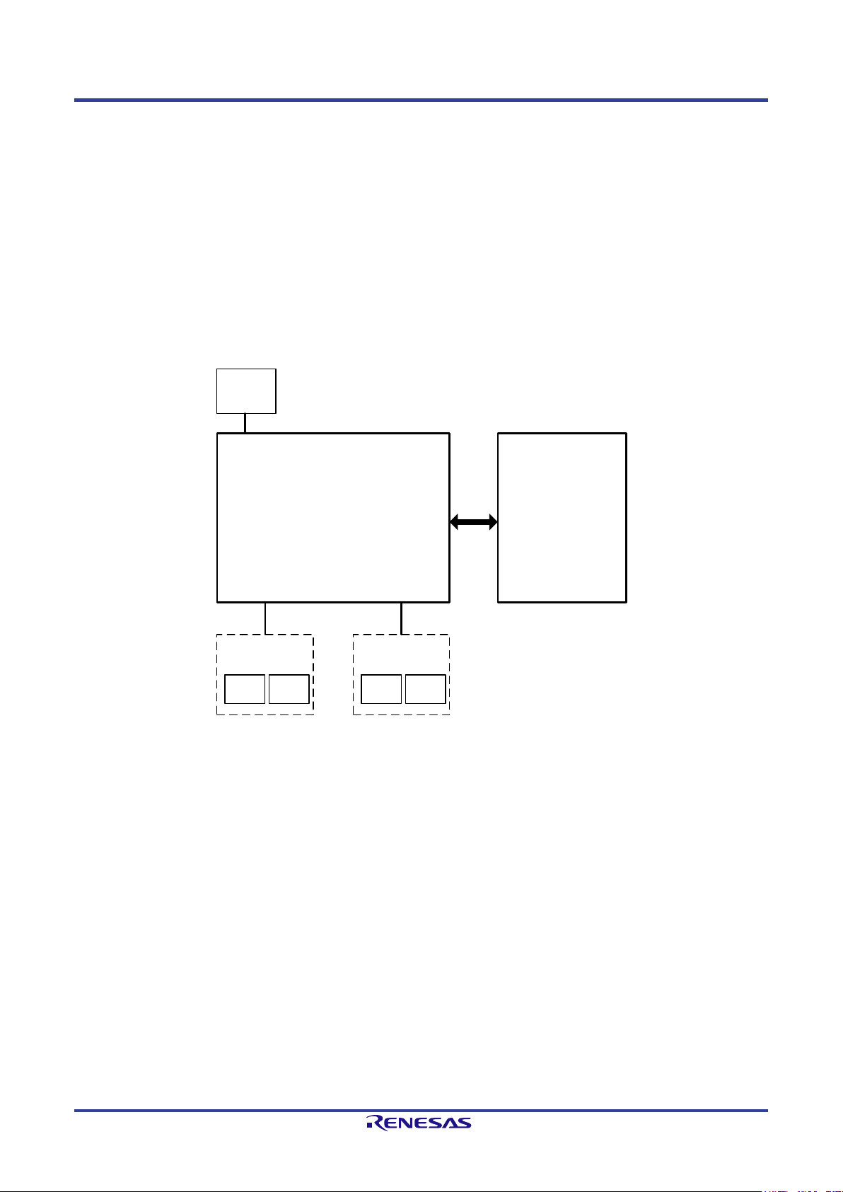
1.2. Abstract
The PROFINET Devic e Chip TPS-1 is designed for easy and cost-efficien t im pl ementation of PROFINET interfaces for automation devices. It is a
highly integrated s ingle chip solution that meets all requirements of th e PROFINET protocols. The configurable host interf aces facili tate the flexible
realization of differen t use cases like direct connec tion of an external host CPU or digital I/Os without additional circuitry.
The TPS-1 com plies with PROFINET Conformance Class C. The integrated components realize the complete interface functionality. The internal
structure is designed to fulfill the requirements of the IRT protocol. Special synchronous signals are available to realize all synchroniza tion tasks. To
support line topologies in PROFINET networks, the TPS-1 is equipped with two integrated PHYs and an integrated IRT switch. Time-critical
PROFINET protocols are supported by hardware.
For the complete implemen tation of a PROFINET device interface, only the TPS-1, a serial Flash device, an oscillator, and the physical adaptations for
the Ethernet interface (transformers and connectors) are needed. The serial Flash component contains the individual chip configuration and firmware
for the PROFINET CPU.
Due to the low space requirement and low power dissipation of the TPS-1, a PROFINET interface can also be integrated into automation devices with
special requirements regarding housing size and protection classes. Conductor routing between the balls is still possible in order to keep down PCB
cost.
Figure 1-1: TPS-1 Overview
R19UH0081ED0107 Rev. 1.07 page 9 of 86
Jul 30, 2018
Page 10

TPS-1 User’s Manual: Hardware 1. Overview
Shared Memory
I/O Int e rfa c e
PHY 2PHY 1
SPI
Slave
Parallel
Interface
8 / 16 Bit
Host Interface
M U X
PROFINET CPU
BootROM
ARM
Core
RAM
PROFINET Core
Time Sync
IRT Switch
Protocol Handlin g
LAN signals
(I2C-bus, link and
Activity), Test Sync
Clock Signals T1 to T6
Clock
Unit
25 MHz
MDI MDI
Link1, Act1, Link2, Act2
Test Sync
JTAG / Debug
Serial Flash
(SPI Slave)
Host Interface /
Parallel - Serial
48 GPIO
Status Info
LEDs
Control Signals
Power Supply
Swit ching Regulator
3.3 V
1.5 V
1.3. Block Diagram
The block diagram shows the internal structure and main components of the TPS-1.
The additional serial boot Flash component, the oscilla tor and the physical adaptat ion for the Ethernet interfaces ar e not listed.
Figure 1-2: TPS-1 Block Diagram
The TPS-1 contains the PROFINET CPU, the PROFINET core, the I/O interface, and the Host Interface for connecting a host CPU.
The PROFINET c o re processes the PROFINET communication. All time-critical services are implemented in hardware to realize high perform ance.
The communication between an externa l host CPU and other PROFINET components is processed by the PROFINET CPU (connection establishment,
administration and management of Application Relations, contr olling of Ethernet connections, setup and monitoring of RT and IRT channels, etc.).
Simple IO in terfaces can be realized wit h the I/O inter face only (e.g. digital I/Os )
R19UH0081ED0107 Rev. 1.07 page 10 of 86
Jul 30, 2018
Page 11

TPS-1 User’s Manual: Hardware 2. Pin function
Pin
Designation
Typ
Function
Remark
M12
CS_FLASH_OUT
O
SPI Master Interface Firmware Flash: Chip Select
(active low)
M13
SPI3_SRXD_IN
I
SPI Master Interface Firmware Flash: Receive Data
Synchronization signals
J11
T1 O Clock signal 1 (isochronous mode, IRT)
G11
T3 O Clock signal 3 (isochronous mode, IRT)
E11
T5 O Clock signal 5 (isochronous mode, IRT)
LED signals device status PROFINET
B11
LED_SF_OUT
O
Control LED „System Fail“
(active low)
B10
LED_MT_OUT
O
Control LED „Maintenance“
(active low)
C9
I2C_1_D_INOUT
I/O
Fiber Optic Port 1: I2C-Bus “Data”
e.g. SC-RJ
C12
LINK_PHY1
O
LINK indication ETHERNET Port 1 (up or down)
(active high)
F13
P1_TX_P
O
ETHERNET Port 1 transmit data (positive)
e.g. RJ45
E13
P1_RX_P
I
ETHERNET Port 1 Receive Data (positive)
e.g. RJ45
B8
P1_SD_P
I
Fiber Optic Port 1: Signal Detect (positive)
e.g. SC-RJ
B9
P1_RD_P
I
Fiber Optic Port 1: Receive Data (positive)
e.g. SC-RJ
B6
P1_TD_OUT_P
O
Fiber Optic Port 1: Transmit Data (negative)
e.g. SC-RJ
A5
P1_FX_EN_OUT
O
Fiber Optic Port 1: Transmitter enable (active high)
e.g. SC-RJ
PHY Port 2
M11
I2C_2_D_INOUT
I/O
Fiber Optic Port 2: I2C-Bus “Data”
e.g. SC-RJ
2. Pin function
2.1. Signal overview and description
Table 2-1 contains an overview about all signals of the TPS-1.
Table 2-1: TPS-1 signal overview and description
e
SPI Master for Boot Flash ROM
(TPS-1)
N13 SPI3_SCLK_OUT O SPI Master Interface Firmware Flash: CLOCK (TPS-1)
(TPS-1) -MISO
M14 SPI3_STXD_OUT O SPI Master Interface Firmware Flash: Send Data
(TPS-1) - MOSI
N12 TEST_SYNC O Clock signal for certification Note 2)
H11 T2 O Clock signal 2 (isochronous mode, IRT)
F11 T4 O Clock signal 4 (isochronous mode, IRT)
D11 T6 O Clock signal 6 (isochronous mode, IRT)
B13 LED_BF_OUT O Control LED „Bus Failure“ (active low)
C10 LED_READY_OUT O Control LED „Device Ready“ (active low)
PHY Port 1
C6 SCLK_1_INOUT O Fiber Optic Port 1: I2C-Bus “Clock” e.g. SC-RJ
D10 ACT_PHY1 O Activity ETHERNET Port 1 (active high)
F14 P1_TX_N O ETHERNET Port 1 transmit data (negative) e.g. RJ45
E14 P1_RX_N I ETHERNET Port 1 Receive Data (negative) e.g. RJ45
A8 P1_SD_N I Fiber Optic Port 1: Signal Detect (negative) e.g. SC-RJ
A9 P1_RD_N I Fiber Optic Port 1: Receive Data (negative) e.g. SC-RJ
A6 P1_TD_OUT_N O Fiber Optic Port 1: Transmit Data (positive) e.g. SC-RJ
R19UH0081ED0107 Rev. 1.07 page 11 of 86
Jul 30, 2018
Page 12

TPS-1 User’s Manual: Hardware 2. Pin function
C11
LINK_PHY2
O
LINK indication ETHERNET Port 2 (up or down)
(active high)
J13
P2_TX_P
O
ETHERNET Port 2 Transmit Data (positive)
e.g. RJ45
K14
P2_RX_N
I
ETHERNET Port 2 Receive Data (negative)
e.g. RJ45
N8
P2_SD_P
I
Fiber Optic Port 2: Signal Detect (positive)
e.g. SC-RJ
N9
P2_RD_P
I
Fiber Optic Port 2: Receive Data (positive)
e.g. SC-RJ
P6
P2_TD_OUT_N
O
Fiber Optic Port 2: Transmit Data (positive)
e.g. SC-RJ
P5
P2_FX_EN_OUT
O
Fiber Optic Port 2: Transmitter enable (active high)
e.g. SC-RJ
N11
XCLK1
I
Connection external oscillator (1), 25 MHz
JTAG – Interface
J10
TM1
I
Test Input 1 (Chip Test - 10k to GND)
(pull down external)
L6
TMS
I
JTAG-Interface: “Test Mode Select”
(pull-up external)
L5
TDI I JTAG-Interface: “Test Data Input”
(pull-up external)
Reset / Test
H12
ATP
I
Test pin for production test (n.c.)
E10
TMC1
I
Test Mode Control 1 (production test)
(pull down external
D6
TEST_1_IN
I
Test Pin 1 for hardware test of the TPS-1
(pull down external
D8
TESTDOUT5
O
Test Data Output 5 (High Speed Signals for PHY)
D9
TESTDOUT6
O
Test Data Output 6 (High Speed Signals for PHY)
L8
TESTDOUT7
O
Test Data Output 7 (High Speed Signals for PHY)
A11
WD_IN
I
Watchdog input (from the Host) (the rising edge resets
(active high)
K11
INT_OUT
O
Interrupt output (to the Host)
(active high)
L11 SCLK_2_INOUT O Fiber Optic Port 2: I2C-Bus “Clock” e.g. SC-RJ
A10 ACT_PHY2 O Activity ETHERNET Port 2 (active high)
J14 P2_TX_N O ETHERNET Port 2 Transmit Data (negative) e.g. RJ45
K13 P2_RX_P I ETHERNET Port 2 Receive Data (positive) e.g. RJ45
P8 P2_SD_N I Fiber Optic Port 2: Signal Detect (negative) e.g. SC-RJ
P9 P2_RD_N I Fiber Optic Port 2: Receive Data (negative) e.g. SC-RJ
N6 P2_TD_OUT_P O Fiber Optic Port 2: Transmit Data (negative) e.g. SC-RJ
Oscillator
P11 XCLK2 O Connection external oscillator (2), 25 MHz
L4 TM0 I Test Input 0 (Chip Test - 10k to GND) (pull down external)
K5 TRSTN I JTAG-Interface: “Test Reset” (pull down external)
L7 TDO O JTAG-Interface: “Test Data Output”
J5 TCK I JTAG-Interface: “Test Clock” (pull-up external)
A12 RESETN I TPS-1 Reset (Global Reset) (active low)
H13 EXTRES O External reference resistor (12.4 kΩ,1 %), connect to
analog GND
recommended)
K10 TMC2 I Test Mode Control 2 (production test) (pull down external
recommended)
recommended)
D7 TEST_2_IN I Test Pin 2 for hardware test of the TPS-1 (pull down external
recommended)
Host interface
the watchdog counter of the TPS-1)
B12 WD_OUT O Watchdog output (to the Host) (active low)
Boot interface (serial)
R19UH0081ED0107 Rev. 1.07 page 12 of 86
Jul 30, 2018
Page 13

TPS-1 User’s Manual: Hardware 2. Pin function
C13
UART6_RX
I
Boot UART “Receive Data“
Test signals for switching regulator
G3
TEST2
I
Test Pin switching regulator (in combination with
PHY supply voltages
C8
VDDQ_PECL_B1
I
PECL buffer power supply 3.3 V (Port 1)
L9
PLL_AGND
PLL analog GND
Pins for switching regulator
G1
BGND
GND for switching regulator (please place bypass
G2
AGND_REG
Analog GND switching regulator
F1
FB I Feedback (regulator)
GPIO_00 -
I/O
(see table “Alternate use of the GPIO”)
C14 UART6_TX O Boot UART “Transmit Data“
P12 BOOT_1 I Forced Boot
H3 TEST1 I Test Pin switching regulator (in combination with
Test2, Test3)
Test1, Test3)
E1 TEST3 I Test Pin switching regulator (in combination with
Test1, Test2)
E12 VDD33ESD Analog test supply, 3.3 V
M8 VDDQ_PECL_B2 I PECL buffer power supply 3.3 V (Port 2)
D14 P1VDDARXTX I Analog Rx/Tx port power supply
Analog 1.5 V V
(must be generated via a filter from
DD
digital 1.5 V power supply) – Port 1
L14 P2VDDARXTX I Analog Rx/Tx port power supply
Analog 1.5 V VDD (must be generated via a filter from
digital 1,5 V power supply) – Port 2
H14 VDDACB I Analog 3.3 V VDD (must be generated via a filter from
digital 3.3 V power supply)
G13 VSSAPLLCB Analog central GND
G14 VDDAPLL Analog central power supply for PHYs, 1.5 V
Pins for core PLL power supply
(core PLL)
L10 PLL_AVDD PLL analog 1.0 V (core PLL)
J1 BVDD I Supply voltage for the switching regulator (3.3 V
supply for the switching transistor)
capacitor between analog power supply and GND).
F2 AVDD_REG Analog VDD for regulator (3.3 V supply),
smoothed voltage to feed the internal POR.
H1 LX O 1.5 V output of the internal switching regulator
Configurable GPIOs
GPIO_47
After reset the GPIO pin are configured as Inputs (no
pull up or down)
Notes:
1. Pin F2 must be always connected to VDD33 (refer Figure 8-2: Internal voltage regulator).
2. The signal TEST_SYNC must be available for certification test (a reachable pad is enou g h) .
Note 1)
R19UH0081ED0107 Rev. 1.07 page 13 of 86
Jul 30, 2018
Page 14

TPS-1 User’s Manual: Hardware 2. Pin function
Pin
Designation
Alternate Use
Description
D5
GPIO 0
LBU WR EN IN
Write Enable
B5
GPIO 1
LBU READ EN IN
Read Enable
C5
GPIO 2
LBU CS IN
Chip Select
C4
GPIO 3
LBU BE 1 IN
Byte Selection (low)
A4
GPIO 4
LBU BE 2 IN
Byte Selection (high)
B4
GPIO 5
LBU READY OUT
Ready Signal TPS-1 (Note 1), (N ote 2)
C3
GPIO 6
LBU DATA0
Data Bit
A3
GPIO 7
LBU DATA1
Data Bit
B3
GPIO 8
LBU DATA2
Data Bit
B2
GPIO 9
LBU DATA3
Data Bit
D3
GPIO 10
LBU DATA4
Data Bit
D4
GPIO 11
LBU DATA5
Data Bit
C1
GPIO 12
LBU DATA6
Data Bit
C2
GPIO 13
LBU DATA7
Data Bit
D2
GPIO 14
LBU DATA8
Data Bit
D1
GPIO 15
LBU DATA9
Data Bit
E2
GPIO 16
LBU DATA10
Data Bit
E3
GPIO 17
LBU DATA11
Data Bit
E4
GPIO 18
LBU DATA12
Data Bit
E5
GPIO 19
LBU DATA13
Data Bit
F5
GPIO 20
LBU DATA14
Data Bit
F4
GPIO 21
LBU DATA15
Data Bit
F3
GPIO 22
LBU A0 IN
Address Bit
G5
GPIO 23
LBU A1 IN
Address Bit
G4
GPIO 24
LBU A2 IN
Address Bit
H5
GPIO 25
LBU A3 IN
Address Bit
H4
GPIO 26
LBU A4 IN
Address Bit
J4
GPIO 27
LBU A5 IN
Address Bit
J3
GPIO 28
LBU A6 IN
Address Bit
K3
GPIO 29
LBU A7 IN
Address Bit
K4
GPIO 30
LBU A8 IN
Address Bit
K2
GPIO 31
LBU A9 IN
Address Bit
L2
GPIO 32
LBU A10 IN
Address Bit
L3
GPIO 33
LBU A11 IN
Address Bit
L1
GPIO 34
LBU A12 IN
Address Bit
M2
GPIO 35
LBU A13 IN
Address Bit
M1
GPIO 36
LBU SEG0 IN
Segment choice 1
M3
GPIO 37
LBU SEG1 IN
Segment choice 2
P3
GPIO 38
HOST RESET IN
Reset Host SPI Interface
N3
GPIO 39
HOST SFRN IN
Start new SPI Transfer (Note 3)
N2
GPIO 40
HOST SRXD IN
SPI receive data
N4
GPIO 41
HOST SCLK IN
SPI Clock
M4
GPIO 42
HOST STXD OUT
SPI transmit data
P4
GPIO 43
HOST SHDR OUT
Header recognized
N5
GPIO 44
LOCAL SCLK OUT
SPI Clock (SPI master IO interface)
M5
GPIO 45
LOCAL SFRN OUT
SPI Chip Select (SPI master IO interface)
M6
GPIO 46
LOCAL SRXD IN
SPI receive date (SPI master IO interface)
M7
GPIO 47
LOCAL STXD OUT
SPI transmit data (SPI master IO interface)
2.2. GPIO multiplexing
Table 2-2: Alternate use of the GPIOs
Note: You can only use one interface exclusively. It is not allowed to use e.g. the parallel and serial host interface at the same time.
Note 1): The “LBU_READY_OUT” is designed to connect only to one microcontroller. If you want to connect additional devices you must
add circuitry to realize the high-impedance state.
Note 2): If your processor does not have a READY Input, you can choose a wait time of 260 ns during each transfer cycle.
Note 3): As soon as the signal HOST_SFRN_IN is set to “1”, no more data is received on the RxD interface. Setting the signal is not a llowed
during an ongoing transfer.
R19UH0081ED0107 Rev. 1.07 page 14 of 86
Jul 30, 2018
Page 15

TPS-1 User’s Manual: Hardware 2. Pin function
Pin
Pin Name
Function
Supply Voltage Generation
G14
VDDAPLL
Analog central power
E12
VDD33ESD
Analog test power
C8,
VDDQ_PECL_B1
PECL buffer power
L10
PLL_AVDD
Power supply for the
D12, D13, L12, L13
AGND
Analog Ground for
A2, A7, A13, F12, K1, K12, M9,
VDD15
Voltage Supply 1.5 V
form Switching Regulator or
2.3. Supply Voltage Circuitry
The TPS-1 works with three operating voltages: VDD15 (1.5 V), VDD33 (3.3 V, IO) and VDD10 (1.0 V, core). Additionally, the on-chip PLL for the
device clock generation requires a sup ply called PLL_AVDD (1.0 V), which is typically a filtered version of VDD10. The integrated PHYs of the
TPS-1 require additional filtered operating voltages.
Table 2-3: Supply Voltage Circuitry
D14,
L14
P1VDDARXTX
P2VDDARXTX
Analog port RX/TX
power supply, 1.5 V
(PHY port 1 and port
2)
supply, 1.5 V (PHY)
H14 VDDACB Analog central power
supply, 3.3 V (PHY)
supply, 3.3 V (PHY)
G13 VSSAPLLCB Analog central GND
(PHY)
M8
VDDQ_PECL_B2
supply 3.3 V (port 1
and port 2)
L9 PLL_AGND Analog Ground for the
internal CPU clock
generation
internal CPU clock
generation (1.0V)
A1, A14, B7, F7, F8, F9, G6, G7,
GND Digital GND
G8, G9, G10, G12, H6, H7, H8,
H9, H10, J2, J6, J7, J8, J9, J12,
M10, N7, N10, P1, P14
PHYs
B1, B14, C7, F6, F10, H2, N1,
VDD33 Voltage Supply 3.3 V External
N14, P7, P10
Must be generated from
VDD15 via a filter.
Must be generated from
VDD33 via a filter.
Must be generated from GND
Core/IO via a filter or
connected to GND Core/IO at
the far end from TPS-1.
P2, P13
E6, E7, E8, E9, K6, K7, K8, K9 VDD10 Voltage Supply 1.0 V External
R19UH0081ED0107 Rev. 1.07 page 15 of 86
Jul 30, 2018
external
Page 16

TPS-1 User’s Manual: Hardware 2. Pin function
T1
J11
Ti (T_IO_Input)
Time at which the input data must be read from
T4
F11
T_IO_OutputValid
This signal indicates when the data for output are
T6
D11
-for further use
2.4. Signals for IRT Communication
The TPS-1 synchronizes the IO device to the PROFINET controller and generates trigger signals that are used for application synchronization.
T_IO_Input relates peripheral inputs and T_IO_Output relates peripheral outputs to the data cycle.
Table 2-4: IRT Communication Signals
Signal Pin Function Comment
TEST_SYNC N12 Start of bus cycle A signal on this pin signalizes a new cycle event. It is
used as well to test the synchronization during the
certification. The signal should be made accessible for
measurement purposes.
process.
T2 H11 To (T_IO_Output) Data can be used by the application at this configured
time.
T3 G11 T_IO_InputValid Time at which the input data must be in the transfer
buffer.
available.
T5 E11 -for further use
R19UH0081ED0107 Rev. 1.07 page 16 of 86
Jul 30, 2018
Page 17

TPS-1 User’s Manual: Hardware 3. Host Interface
TPS
-1
0x8000
0x8004
0x0000
0xFFFF
Magic Number
NRT Area Size
ARM CPU
Application CPU
The application CPU read
the Magic Number to
recognize the start up of
the TPS-1
Operating mode
Separate Read / Write signal (Intel Mode)
Polarity of ready signal
Ready Signal “active low”
Data bus width
8 bit
3. Host Interface
The host interface is designed to connect external mic r o processors. These processors access the internal sh ared memory of the TPS-1 in order to
exchange cyclic or acyclic data with the PROFINET IO interface. The shared memory has an address space of 64 Kbyte. The data exchange is
processed with the help of an “Event Unit”.
Another way to inform the external host CPU about a new PROFINET status is the integrated interrupt system. The parallel interface can be switched
to Motorola or Intel mode.
It is only possible to use the Host parallel interface or the Host serial interface. It is not possible to use both at the same time.
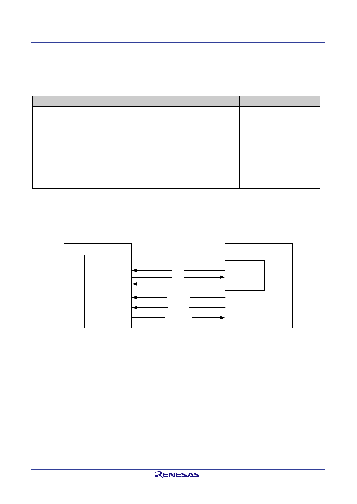
3.1. Testing DPRAM Interface
For testing the DPRAM Interface it is useful to have addresses with defined values. After start of the TPS-1 firmware the TPS-1 writes the magic
number and the NRT Area Size into the addresses 0x8000 and 0x8004.
Figure 3-1: TPS-1 with address page 16 Kbyte
3.2. Parallel Interface
3.2.1. Operating modes of the parallel interface
The parallel interface can be used with an 8-bit or 16-bit data bus.
Table 3-1: Operating Modes of the parallel interface
Setting Description
Read-/Write-Control (Motorola Mode)
Ready Signal “active high”
The configuration of the parallel interface is also done with “TPS Configurator”.
16 bit
R19UH0081ED0107 Rev. 1.07 page 17 of 86
Jul 30, 2018
Page 18
TPS-1 User’s Manual: Hardware 3. Host Interface
LBU
_
Ax_
IN
(13
:
0)
A
(
15
:
0
)
A
(13
:0
)
A(15:14)
Ext
. Host CPU
LBU
_Ax_IN(15:14)
LBU_Ax_IN(11:0)
A(13:0)
A(11:0)
A(13:12)
Ext. Host CPU
TPS-1
Host Interface
LBU_SEG(1:0)_IN
Host Interface
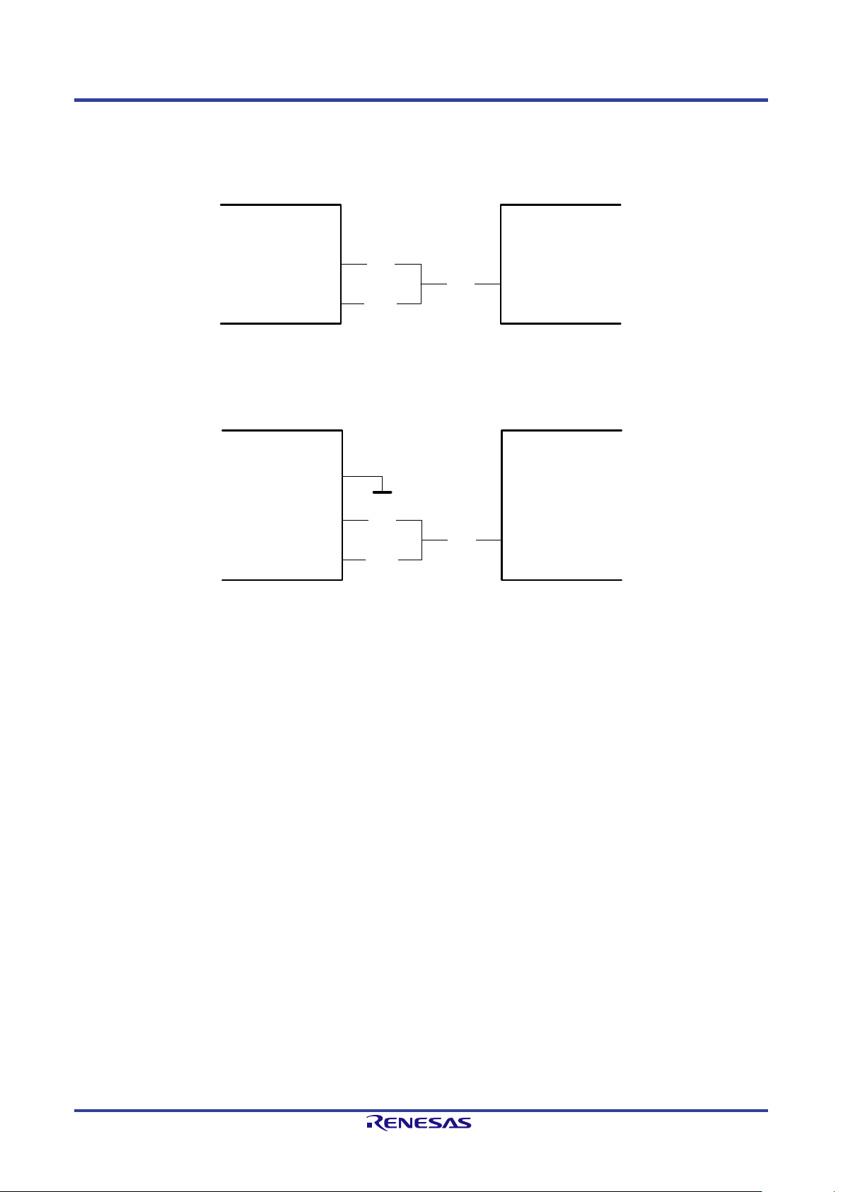
3.2.2. Signal description of the parallel interface
The shared memory has an address space of 64 Kbyte (refer to chapter “Shared memory structure”). The typical pag e size is 16 KByte. For a correct
alignment you have to connect the highest address bits to the signals LBU_SEG0_IN and LBU_SEG1_IN (see Table 3-2, Figure 3-2 and Figure 3-3).
TPS-1
LBU_SEG(1:0)_IN
You can also choose a pa ge size of 4 Kbyte. When you choose 4 Kbyte pages you have less space inside the NRT area for configuration slots and
subslots.
LBU_Ax_IN(13:12)
Figure 3-2: TPS-1 with address page 16 Kbyte
Figure 3-3: TPS-1 with address page 4 Kbyte
R19UH0081ED0107 Rev. 1.07 page 18 of 86
Jul 30, 2018
Page 19

TPS-1 User’s Manual: Hardware 3. Host Interface
0: write; 1: read
no function (Motorola-Mode)
LBU_BE_1_IN
Byte Selection 1
LBU_READY_OUT
Ready Signal
polarity changeable
LBU_A0_IN – LBU_A13_IN
Address lines 0 - 13
LBU_SEG1_IN
High Bit of the segment
page selection
0
1
8-Bit HIGH
Other combinations
Not allowed
01 1 0
8-Bit access
11 1 0
8-Bit access
Table 3-2 describes all signals of the parallel Host interfac e.
Table 3-2: Parallel Host Interface Layout
Signal designation Function Remarks
LBU_WR_EN_IN Write Control active low (Intel mode)
(Motorola mode)
LBU_READ_EN_IN Read Control active low (Intel-mode)
LBU_CS_IN Chip Select
LBU_BE_2_IN Byte Selection 2
LBU_DATA0 – LBU_DATA15 data line 0 – 15
LBU_SEG0_IN Low Bit of the segment page selection
During a memory access, the TPS-1 behaves like a „16-bit Little Endian“ device with an 8-bit or 16-bit memory. The possible access types are listed in
Table 3-3.
Table 3-3: 16-Bit External Host Databus
LBU_BE_2_IN LBU_BE_1_IN Access type
1 0 8-Bit LOW
0 0 16-Bit
Table 3-4: 8-Bit External Host Databus
LBU_A[1:0] LBU_BE_2_IN LBU_BE_1_IN Access type
00 1 0 8-Bit access
10 1 0 8-Bit access
Other combinations Not allowed
An illegal access results in an „Error-IRQ“ from the event u nit.
R19UH0081ED0107 Rev. 1.07 page 19 of 86
Jul 30, 2018
Page 20

TPS-1 User’s Manual: Hardware 3. Host Interface
LBU_SEG(1:0)
Selected Page
0 0
Page 00
0 1
Page 01
1 0
Page 02
1 1
Page 03
0x
0000
0x
2000
0x
8000
0xFFFF
NRT
-Area
IO
-RAM
Event
-Unit
16 K Page Size
0x4000
0xC000
Page 00
Page 02
Page 01
Page 03
3.2.3. Memory Segmentation at 4 kByte and 16 kByte page size
You decide the page size with the TPS Configurator. A connected Host CPU selected the pages with the LBU_SEGx_IN signals. Table 3-5 shows the
page decoding.
Table 3-5: Page selection with LBU_SEGx_IN signals
The segmentation with 16 Kbyte pages is shown in Figure 3-4. With 16 address lines you can reach the whole 64 kByte address space.
Figure 3-4: 16 kByte page size
R19UH0081ED0107 Rev. 1.07 page 20 of 86
Jul 30, 2018
Page 21

TPS-1 User’s Manual: Hardware 3. Host Interface
0x0000
0x
2000
0x
8000
0xFFFF
NRT
-Area
IO
-RAM
Event-Unit
4 K Page Size
0x3000
0x9000
Page 00
Page 02
Page 01
Page 03
0x1000
0x9FFF
Using the 4 kByte address pages limits the available a d dress space of the NRT area. Figure 3-5 shows the pages. You can reach the complete EventUnit and th e complete IO-RAM. Out of the NRT area you can only use the address space between 0x8000 and 0x9FFF.
Figure 3-5: 4 kByte page size
Because of the page size, i t is not possible to use the max. Possible number of slots and subslots. Other page sizes than 16 kByte and 4 kByte are not
possible.
R19UH0081ED0107 Rev. 1.07 page 21 of 86
Jul 30, 2018
Page 22
TPS-1 User’s Manual: Hardware 3. Host Interface
TPS-1
HOST-CPU
RDN
A0 – A15
CSN
AD0 – AD7
A14
A15
WR0N
LBU_CS_IN
LBU_BE_1_IN
LBU_BE_2_IN
LBU_READ_EN_IN
LBU_SEG0_IN
LBU_SEG1_IN
LBU_WR_EN_IN
LBU_A0_IN – LBU_A13_IN
LBU_DATA0 – LBU_DATA7
WR0N (byte)
RDN
AD0 – AD7
A0 – A15
&
0
0
0
INTN
INT_OUT
INT Port
READYN
LBU_READY_OUT
WAITN
„1"
CSN
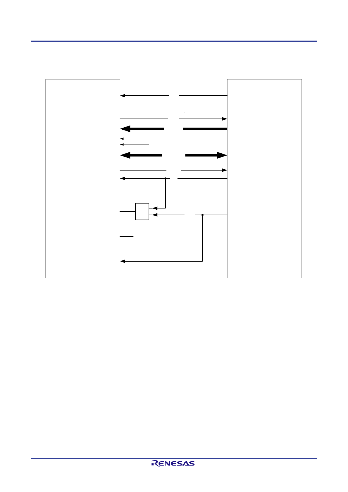
3.2.4. Connection example for an 8bit data bus
Figure 3-6 shows a connection example of an 8-bi t data bus to the TPS -1.
Figure 3-6: Connection example for an 8-bit data bus
R19UH0081ED0107 Rev. 1.07 page 22 of 86
Jul 30, 2018
Page 23
TPS-1 User’s Manual: Hardware 3. Host Interface
TPS
-
1
HOST
-
CPU
RDN
A1 – A15
CSN
AD
0
– AD15
A14
A15
WR
0N
WR1N
LBU
_
CS_
IN
LBU_BE_1_IN
LBU_BE_2_IN
LBU_READ_EN_IN
LBU
_
SEG
0
_IN
LBU_
SEG
1
_IN
LBU_WR_EN
_IN
LBU_A1_IN – LBU
_
A13
_
IN
LBU_DATA0 – LBU_DATA
15
WR0N
WR
1N
RDN
AD0 – AD15
A1 – A15
&
0
0
0
INTN
INT
_
OUT
INT Port
READYN
LBU_
READY
_
OUT
WAITN
&
0
0
0
&
0
0
0
CSN
LBU_
A0
_IN
10
K
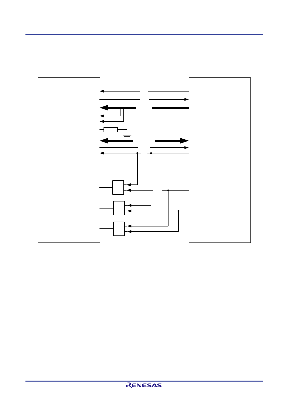
3.2.5. Connection example for a 16-bit data bus
Figure 3-7 shows the connection of a 16-bit CPU to the TPS-1. The connection uses a 16-bit data bus and an address bus of 16 bit. Thus, it is possible
to access the entire addr ess space of 64 KByte. Address line A0 should not be connected using the 16-bit data bus. The Address line LBU_A0_IN
should be connected to a pull down.
Figure 3-7: Connection of a V850 CPU with a 16-bit data bus
R19UH0081ED0107 Rev. 1.07 page 23 of 86
Jul 30, 2018
Page 24
TPS-1 User’s Manual: Hardware 3. Host Interface
Pin
GPIO Pin
N3
GPIO_39
HOST_SFRN_IN
Serial Frame
The start of a new SPI
N4
GPIO_41
HOST_SCLK_IN
Serial Clock Input
Serial Clock driven by the
P4
GPIO_43
HOST_SHDR_OUT
Serial Header Information
header information available
TPS-1
SPI-SLAVE
HOST-CPU
(V850ES/JG2)
MOSI
MISO
SCLK
CSIBx-Master
SOBx
SIBx
SCKBx
HOST_STXD_OUT
HOST_SRXD_IN
HOST_SCLK_IN
SPI-Reset
SFRN_IN
SHDR_OUT
HOST_RESET_IN
HOST_SFRN_IN
HOST_SHDR_OUT
P02 (Output)
P03 (Output)
P04 (Input)
3.3. SPI Slave Interface
Another way to connect a host CPU is the SPI interface. The maximum speed for s er ial access to the shared m emory is 25 MHz. The tr ansmission clock
frequency should range between 1 MHz and 25 MHz. A control unit for processing the SPI Master commands is implemented into the TPS-1.
The SPI Master commands are described in this chapter.
Table 3-6: SPI host interface signals
Signal designation Function Remarks
P3 GPIO_38 HOST_RESET_IN Serial Reset The SPI Slave interface can
be reset by using this signal
(signal is active high).
transfer is signalized.
N2 GPIO_40 HOST_SRXD_IN Serial Data Input MOSI (Master out Slave in)
SPI Master
M4 GPIO_42 HOST_STXD_OUT Serial Data Output MISO (Master in Slave out)
An unknown or wrong SPI access causes an „Error-IRQ“ that is reported to the host CPU by the event unit.
The clock phase and the CPOL (clock polarity) is adjustable (active low, active high).
The following figure shows the connection of a host CPU (V850ES/JG2) to the SPI Slave interface of the TPS-1. The “chip select” line is not
connected. The data transfer is cont rolled by the status of the “clock line” (CSI-Master).
The pins HOST_RESET_IN, HOST_SFRN_IN and HOST_SHDR_OUT are not supported directly by the HOST-CPU. They have to be simulated by
the pins P02, P03 and P04.
R19UH0081ED0107 Rev. 1.07 page 24 of 86
Jul 30, 2018
Figure 3-8: Connection of a V850 CPU to the SPI interface
Page 25

TPS-1 User’s Manual: Hardware 3. Host Interface
Command
Address
Address
Length
Length
3.3.1. Serial access to the shared memory
The access to the shared memory is processed with command bytes that are part of the SPI-Header. The command structure depends on the device.
Generally, an SPI interface works like a shift register. The clock is driven by the SPI master. After processing the SPI command, the SPI slave sends th e
requested data to the host CPU (or data is only sent to the SPI slave). As long as the chip select signal is active, data are exc hanged between the devices
(master – slave).
3.3.1.1. Header structure
The content and meaning of SPI data is defined by the implementation of the SPI slave. The following chapter describes the structure of the SPI slave
commands.
Table 3-7: SPI header structure
Header Data
Byte 0 Byte 1 Byte 2 Byte 3 Byte 4 Byte 5 – max.
1 Byte 1 Byte 1 Byte 1 Byte 1 Byte 1 Byte .. max. length Shared Memory
An indirect command contains the length information in byte 3 and 4. A direct command contains the length information in the bits 0 to 3 of the
command byte. The maximum ad dress access is limited t o 15 byte.
R19UH0081ED0107 Rev. 1.07 page 25 of 86
Jul 30, 2018
Page 26

TPS-1 User’s Manual: Hardware 3. Host Interface
b7 b6
b
5 b
4
b3
b2
b
1 b0
Access Area
Direct IO Length
b6 = 1 (write)
b7 = 1 (read)
3.3.1.2. Structure of a comm and byte
Figure 3-9 shows the format of a command byte. A command byte can be followed by an address area, length area and data.
Figure 3-9: Command b yte for SPI slaves (host interface)
The bits of the command byte have the following meaning:
• b7 indicates a read command,
• b6 indicates a write command,
• b5 and b4 describe the addressing range:
„00“: MEM ac cess to the complete shared m emory (64 Kbyte)
„01“: IO access to the input/output area
„10“: access to a multicast provider CR (only write)
„11“: fractional access to an I-CR (b6 = 1) or MC-CR (b6 = 0)
• b3 .. b0 contain the length for an optimized direct data access
„= 0000“: no d irect acces s.
„≠ 0000“: direct access length information (maximum of 15 byte)
R19UH0081ED0107 Rev. 1.07 page 26 of 86
Jul 30, 2018
Page 27

TPS-1 User’s Manual: Hardware 3. Host Interface
This gives the external host CPU access to the complete address space of 64 Kbyte.
Read MEM Direct
Reads from the transferred
0b1000_nnnn
2 0 1 - 15
With this command, the external host CPU can read from and write to the complete 64
Read MEM
Reads from the transferred
0b1000_0000
2 2 1 – 32K
3.3.1.3. Command overview
The SPI commands are optimized for the use with PROFINET. The following table describes the implemented commands.
Table 3-8: Implemented SPI commands
DirectMEM-
Access
Each access transfers not more than 15 byte. The length is coded in the command
byte.
Command Description
address. The length is
coded in the command byte.
Write MEM Direct Writes to the transferred
address. The length is
coded in the command byte.
MEM-Access
Kbyte address space with a maximum data length of 64 Kbyte (access to cyclic and
acyclic data).
Command Description
address. The length is
coded in the length byte.
Write MEM Writes to the transferred
address. The length is
coded in the length byte.
Command
code
(0x8n)
0b0100_nnnn
(0x4n)
Command
code
(0x80)
0b0100_0000
(0x40)
Number of
address
bytes
Number of
length
bytes
Number
of data
bytes
2 0 1 - 15
Number of
address
bytes
Number of
length
bytes
Number
of
data
bytes
(64K)
2 2 1 – 32K
(64K)
R19UH0081ED0107 Rev. 1.07 page 27 of 86
Jul 30, 2018
Page 28

TPS-1 User’s Manual: Hardware 3. Host Interface
B7 B6 B5
B4 B3 B1B2 B0 B15 B14 B13 B12 B11 B9B10 B8 B7 B6 B5 B4
HOST_SCLK_IN
SPI-Header
SPI-Data
B7 B6 B5 B4 B3 B1B2 B0
B15 B14 B13 B12 B11 B9B10 B8
DummyDummyDummyDumm
y
MSBit
LSBit LSBit
MSBit
HOST_SFRN_IN
HOST_SRXD_IN
HOST_STXD_IN
HOST_SHDR_OUT
Motorola SPI
format:
SPO = 0
SPH = 0
3.3.2. SPI Slave Interface Timing
The SPI transfer is controlled by the signal HOST_SFRN_IN. A chip select signal is not used.
3.3.2.1. SPI Slave Interface Typical Timing
The following figure shows a typical SPI-Slave Timing (Motorola Mode).
Each transfer (a transmission of 8 bit) starts with a falling edge of the HOST_SFRN_IN signal. The transmission is controlled by the clock signal. All
receive and transmit da ta is processed in the Little-Endian format by the serial host interface. When connecting a Big-Endian Host System, the format
has to be changed into the correct order.
There is a maximum clock frequency of 25 MHz possible using t his interface .
Figure 3-10: SPI Slave Timing
The signal HOST_SHDR_OUT is used to inform the SPI master, that header information has been received (HOST_SHDR_OUT = 0). When the
signal goes to high level (HOST_SHDR_OUT = 1), payload data is expected.
R19UH0081ED0107 Rev. 1.07 page 28 of 86
Jul 30, 2018
Page 29

TPS-1 User’s Manual: Hardware 3. Host Interface
B7 B6 B5 B4 B3 B1B2 B0
B15 B14 B13 B12 B11 B9B10 B8
HOST_SCLK_IN
B7 B6 B5B4 B3 B1B2 B0
B15 B14 B13 B12 B11 B9B10 B8
MSBit
LSBit
LSBit
MSBit
HOST_SFRN_IN
HOST_SRXD_IN
HOST_STXD_IN
Motorola SPI
format:
SPO = 0
SPH = 0
T1
T2 T3
2 Byte
T1
min. 1 system clock
The HOST_SFRN_IN signal may become active not
T3
Min. 3 system clock
There must be at least 3 system clocks between the
As soon as the signal HOST_SFRN_IN is set to “1”, no more da ta is received on the RxD interface. Setting the signal is not allowed during an ongoing
transfer.
Figure 3-11: SPI Transfer with HOST_SFRN_IN Signal
The HOST_SFRN_IN signal is required to synchronize bytes transferred to the TPS-1 with the periphera l interface. The timing to be observed can be
seen in Figure 3-11 (T1, T2 and T3).
The timing is based on the system clock of the TPS-1 (100 MHz, 10 ns); it must a s well be applied in the situations shown in Figure 3-12, Figure 3-13
and Figure 3-14.
Table 9: Timing HOST_SFRN_IN signal
Phase Timing Description
earlier than one system clock after the rising edge of
HOST_SCLK_IN.
T2 min. 2 system clock The signal HOST_SFRN_IN must be active for at least
2 system clocks.
falling edge of HOST_SFRN_IN and the active edge of
HOST_SCLK_IN.
R19UH0081ED0107 Rev. 1.07 page 29 of 86
Jul 30, 2018
Page 30

TPS-1 User’s Manual: Hardware 3. Host Interface
B23
B22
B21
B20
B19
B17
B18
B16
HOST_SCLK_IN
HOST_SFRN_IN
HOST_SRXD_IN
B9
B10
B8
B9
B10
B8
Dummy
Dummy
Dummy
Dummy
Dummy
Dummy
Dummy
Dummy
B7
B6
B5
B4
B3
Dummy
Dummy
Dummy
Dummy
Dummy
HOST_STXD_OUT
SPI-Status
SPI-RD-Data
Busy_Enable
Busy
Motorola SPI
format:
SPO = 0
SPH = 0
B
23
B
22
B
21
B
20
B
19
B
17B
18
B
16
HOST
_
SCLK
_
IN
HOST
_
SFRN
_
IN
HOST_SRXD_IN
B9
B10
B8
B9
B10
B8
Dummy
Dummy
Dummy
Dummy
Dummy
Dummy
Dummy
Dummy
B7
B6
B5
B4
B3
Dummy
Dummy
Dummy
Dummy
Dummy
HOST_STXD_OUT
SPI-
Status SPI-
RD
-Data
Busy
_
Enable
Busy
Motorola SPI
format:
SPO = 0
SPH = 0
3.3.2.2. SPI Slave Interface Handshake Mode
If the head er contains a r ead or exchange command, it is necessary to wa it for a short time after tr ansferring the header in order to enable t he slave
interface to collect the data before transferring. There are two methods to do this.
You can enable the busy mode (polarity high or low) or use the wait mode.
3.3.2.2.1. SPI Slave Interface Handshake Busy Mode
The handshake mode and the polarity can be configured with the TPS Configurator.
After transmitting the header information, the Busy_Enable signal is set (no clock and HOST_SRXD_IN in high or low – depends on the Busy_POL).
When the SPI slave interface can transmit the requested data, the HOST_STRX_OUT signal is set to its active level. This indicates to the SPI master
that it can start the next cycle and the master release the Busy_ Enable signal. This forces t he SPI slave to r elease the Bu sy level and the master starts the
next clock cycle .
Figure 3-12: SPI Read-Timing (Busy_POL=0)
Figure 3-13: SPI Read-Timing (Busy_POL=1)
R19UH0081ED0107 Rev. 1.07 page 30 of 86
Jul 30, 2018
Page 31

TPS-1 User’s Manual: Hardware 3. Host Interface
B23
B22
B21
B20
B19
B17
B18
B16
HOST_SCLK_IN
HOST_SFRN_IN
HOST_SRXD_IN
B9
B10
B8
B9
B10
B8
Dummy
Dummy
Dummy
Dummy
Dummy
Dummy
Dummy
Dummy
B7
B6
B5
B4
B3
Dummy
Dummy
Dummy
Dummy
Dummy
HOST_STXD_OUT
SPI
-
Status SPI
-
RD-
Data
Motorola SPI
format:
SPO = 0
SPH
= 0
Wait_Time
12.5
2.46 – 2.5
3.3.2.2.2. SPI Slave Interface Handshake Wait Mode
When using t he Handshake Wait Mode, the SPI master deactivates the data transfer after the header has been transmitted and starts a wait time. During
this time, the SPI Slave can provide the requested data.
Figure 3-14: SPI Read-Timing Wait Mode
The following equation describes the Wait-Time after the command bytes, before starting the payload data:
= ((32 * f
T
Wait
The followin g table shows a rough estimat ion for two frequencies:
) - 10); (T
sys/fSPI
Wait
* 1/f
= Wait-Time)
sys
Table 3-10: SPI Wait Time
SPI Clock (MHz) Wait-Time (µs)
25 1.18 – 1.2
R19UH0081ED0107 Rev. 1.07 page 31 of 86
Jul 30, 2018
Page 32

TPS-1 User’s Manual: Hardware 3. Host Interface
e.g. TPS _GetVa lue16() e.g. TPS_Ge tVal ue16()
HOST _SCLK_IN
Wait Time between
two SPI transfers (L)
1. Da ta - tra nsfer
HOST _SRXD_IN
HOST _STXD _OUT
CMD-
Byte
ADRByte
ADRByte
Data
Byte
Data
Byte
CMD-
Byte
ADR-
Byte
ADR-
Byte
Data
Byte
Data
Byte
CMDByte
ADRByte
ADRByte
Data
Byte
Data
Byte
CMD-
Byte
ADRByte
ADRByte
Data
Byte
Data
Byte
2. Da ta - tra nsfer
The time between two complet e data transfers is calculated with the following equation:
L = ((4 * (T
+ 10)) – 8 * f
Wait
) (L * 1/fsys = break between two cycle);
sys/fSPI
The following figure shows two SPI transfers (each 5 byte lo ng ) and the wait time between this cycles.
Figure 3-15: Two SPI transfers with wait time
R19UH0081ED0107 Rev. 1.07 page 32 of 86
Jul 30, 2018
Page 33

TPS-1 User’s Manual: Hardware 3. Host Interface
Motorola SPI
format:
SPO = 0
SPH = 0
B5
B4
B3 B1B2 B0
HOST_SCLK_IN
SPI-Header
MSBit
LSBit
MSBit
HOST_SFRN_IN
HOST_SRXD_IN
HOST_STXD_IN
HOST_SHDR_OUT
B15
B14
B13
B12
4 x SysCLK
B7
B6
B5
B4
B3
B2
B1
B0
B7
B6
B5
B4
B3
B2
B1
B0
HOST_RESET_IN
SPI-Data
MSBit
LSBit
Dummy
Dummy
Dummy
Dummy
Dummy
Dummy
Dummy
Dummy
Dummy
Dummy
3.3.3. SPI Slave Interface Reset Timing
Figure 3-14 describes the behavior when a reset for t he SPI Slave interface occurs. The communication process is interrupted and after a wait time of 4
system clocks (40 ns for the TPS-1), the nex t transf er can start.
Figure 3-16: SPI Slave Reset Timing
The signal HOST_RESET_IN is the only way to set the slave interface to a defined status. The signal is active high. During the normal operation the
signal is set to “low level”.
If you want to ensure that the previous transfer is completed terminated, the following waiting time must be observed:
= ((32 * f
T
Wait
This time applies after the rising clock edge of HOST_SCLK_IN. In addition, HOST_RESET_IN may only become active simultaneously with
HOST_SFRN_IN at the earliest.
) - 10) + 4 clock pulse;
sys/fSPI
R19UH0081ED0107 Rev. 1.07 page 33 of 86
Jul 30, 2018
Page 34

TPS-1 User’s Manual: Hardware 4. Shared memory structure
0x0000
0x2000
0x2800
0x8000
reserved
reserved
Ou tput Area
Input Area
MC Provider
Area
(2k Byte)
TPS-1 Information Area
Device Vendor Information
RecordMailbox
Supervisor AR
0xFFFF
IO RAM
NRT
Area
(32k Byte)
Ev ent and IO
area
(32k Byte )
Slot/Subs lot conf iguration
reserved
TCP/IP Mailbox
AR0
RecordMailbox
AR0
AlarmMailbox high
AR0
AlarmMailbox low
AR1
RecordMailbox
AR1
AlarmMailbox high
AR1
AlarmMailbox low
RecordMailBox
Implicit AR
Event-Unit
4. Shared memory structure
Figure 4-1 describes the structure of the shared memory. The serial and parallel interfa ces see the sa me memory image (6 4 Kbyte). If you use 4 kByte
memory pages then you can only use the NRT Area up to 0x9FFF.
R19UH0081ED0107 Rev. 1.07 page 34 of 86
Jul 30, 2018
Figure 4-1: TPS-1 Shared Memory Structure (Dual Ported RAM)
Page 35

TPS-1 User’s Manual: Hardware 4. Shared memory structure
TPS-1
PROFINET
STACK
NRT-Area
Input / Output
Area
RT-DATA
Access
Library
Host
parallel
or serial
access
SWITCH
The structure of the configuration written into the NRT area is checked by the TPS-1 firmware. If there are structure errors th e TPS-1 firmware does not
start.
The host interface and the NRT area are accessible in a continuous address space.
Figure 4-2: General overview host interface
Access to the NRT area and I npu t/ Output area is processed with the support of a software library. The memory area (shared memory) is used for the
access to acyclic and cy clic data. The size depends on the device.
Exchange of the cyclic data is managed in the peripher al interfac e ( i nput / output area). The structure of this area is fixed . It is possib l e to manage one
AR (Ap plication Relations) in the first release.
• one I-Data-CR
• one O-Data CR
The IO data has a maximum size of 1016 Byte (cyclic data), dynamically distributed to two ARs.
Note: A maximum data size of 1016 Byte i s possible with stack version 1.4.0.14 or newer. Thi s data size can be flexibly d istributed over 2
PROFINET application rel ations (example: one AR uses 256 Bytes, the other AR uses 760 Bytes). With stack versions earlier than 1.4.0.14
the maximum data size is limited to 340 Bytes for each of the two configurable application relations.
Note
R19UH0081ED0107 Rev. 1.07 page 35 of 86
Jul 30, 2018
Page 36

TPS-1 User’s Manual: Hardware 4. Shared memory structure
Event Register
TPS-1
(32-Bit)
Event Register
Applic ation CPU
(32 Bit)
Host
Application
CPU
TPS-1
PROFINET
CPU
Write
Read
Read
Write
4.1. Event communication with the TPS-1 Firmware
After system start up the communication between the TPS -1 and the host CPU is processed by the event register (one r eg ister for ea ch directio n). Each
bit of the event register causes a special action.
Figure 4-3: TPS-1 Event Communication
For process changes of the event register the TPS-1 and the host CP U has to poll these registers. You can also use an interrupt control mode if the host
CPU supports this.
The event bits corresponding to the mail box access are not ambiguous. After recei v ing this event it is necessary to check each mail box. In the header
of the respective mail b o x , the READ_FLAG is set.
The following tables describe the structure of the event register f o r each direction.
For each possible event bit in the event register a special callback function is implemented. For example, the event
“EVENT_ONCONNECT_REQ_REC_0” (bit 13) indicates a Connect.Req for the first AR (AR0). In this case the check function will call in the
function OnConnect() and process the event.
R19UH0081ED0107 Rev. 1.07 page 36 of 86
Jul 30, 2018
Page 37

TPS-1 User’s Manual: Hardware 4. Shared memory structure
Name
Description
TPS_Event_Bits (Firmware Stack -> Host)
TPS_EVENT_ONCONNECTDONE_AR1
Set when a connection for IOAR1 is established.
TPS_EVENT_ON_PRM_END_DONE_IOAR1
All parameter available for IOAR1.
TPS_EVENT_ON_PRM_END_DONE_IOSAR
All parameter available for IOSAR
TPS_EVENT_ONABORT_IOAR1
Connection for IOAR1 is disconnected.
TPS_EVENT_ONALARM_ACK_0
Set when an alarm (low priority) is acknowledged from
TPS_EVENT_ONCONNECT_REQ_REC_0
Set if a Connect.Req for the first AR (AR0) is received.
TPS_EVENT_ON_SET_IP_PERM
IP address should be set permanent.
TPS_EVENT_ONDCP_BLINK_START
Action LED flashing is should start.
TPS_EVENT_ON_LED_STATE_CHANGE
New state of TPS LEDs was set.
TPS_EVENT_ON_SET_DEVNAME_PERM
A dcp.set request to change the name of station was
TPS_EVENT_ON_FSUDATA_CHANGE
FSU parameter was written or changed by TPS-1
4.2. Events from the TPS-1 firmware to the host
Table 4-1: TPS-1 Firmware Events
TPS_EVENT_ONCONNECTDONE_AR0 Set when a connection for IOAR0 is established.
TPS_EVENT_ONCONNECTDONE_AR2 Set when a connection for IOSAR is establ ished.
TPS_EVENT_ON_PRM_END_DONE_IOAR0 All parameter available for IOAR0.
TPS_EVENT_ONABORT_IOAR0 Connection for IOAR0 is disconnected.
TPS_EVENT_ONABORT_IOSAR Connection for IOSAR is disconnected.
TPS_EVENT_ONREADRECORD Set when a Record Read Request is available in a
Record-Mailbox.
TPS_EVENT_ONWRITERECORD Set when a Record Write Request is available in a
Record-Mailbox.
the controller.
TPS_EVENT_ONDIAG_ACK Set if a diagnostic alarm is acknowledged.
TPS_EVENT_ONCONNECT_REQ_REC_1 Set if a Connect.Req for the first AR (AR1) is received.
TPS_EVENT_ONCONNECT_REQ_REC_2 Set if a Connect.Req for the third AR (AR2) is received.
TPS_EVENT_ON_SET_DEVNAME Device name is send to the host application.
TPS_EVENT_ON_SET_IP_TEMP IP address should only be set temporary.
TPS_EVENT_ONDCP_FACTORY_RESET All settings are set to the factory settings.
TPS_EVENT_ONALARM_ACK_1 Set when an alarm (high priority) is acknowledged from
the controller.
TPS_EVENT_RESET A RESET of the Host CPU is forced.
TPS_EVENT_ETH_FRAME_REC A TCP/IP Ethernet Frame is received.
TPS_EVENT_TPS_MESSAGE A TPS communication packet was received and is
available in the Ethernet mailbox.
received.
R19UH0081ED0107 Rev. 1.07 page 37 of 86
Jul 30, 2018
firmware.
Page 38

TPS-1 User’s Manual: Hardware 4. Shared memory structure
Name
Description
APP_EVENT_CONFIG_FINISHED
Set by TPS_StartDevice(). Configuration is valid.
APP_EVENT_APP_RDY_1
Set when the device is complete parameterized for AR1.
APP_EVENT_RECORD_DONE
Set after processing a request of the Record Mailbox.
APP_EVENT_ONCONNECT_OK_0
Connect AR0 ok.
APP_EVENT_ONCONNECT_OK_2
Connect AR2 ok.
APP_EVENT_ABORT_AR_1
AR1 is disconnected by the host.
APP_EVENT_PULL_SUBMODULE
A submodule is pulled out of the device.
APP_EVENT_ALARM_SEND_REQ_AR0
Set when an alarm for the AR0 is reported.
APP_EVENT_ALARM_SEND_REQ_AR2
Set when an alarm for the AR2 is reported.
APP_EVENT_ETH_FRAME_SEND
A TCP/IP Ethernet frame (MAC) should be send from the mailbox.
APP_EVENT_READ_OUTPUT_DATA
Process data read.
APP_EVENT_APP_MESSAGE
The application filled the Ethernet mailbox with a record request for the
4.3. Events from the host to the TPS-1 firmware
Table 4-2: Host Events
Host Event Bits (Host -> Firmware Stack)
APP_EVENT_APP_RDY_0 Set when the device is complete parameterized for AR0.
APP_EVENT_APP_RDY_2 Set when the device is complete parameterized for AR2 (Supervisor
AR).
APP_EVENT_DIAG_CHANGED Set when the status of the diagnostic mailbox changed.
Is set after the host processes the Framelayout-Parameter out of a
Connect Request of the AR0.
APP_EVENT_ONCONNECT_OK_1 Connect AR1 ok.
Is set after the host processes the Framelayout-Parameter out of a
Connect Request of the AR1.
Is set after the host processes the Framelayout-Parameter out of a
Connect Request of the AR2.
APP_EVENT_ABORT_AR_0 AR0 is disconnected by the host.
APP_EVENT_ABORT_AR_2 AR2 is disconnected by the host.
APP_EVENT_RETURN_SUBMODULE A submodule returns in to the device.
APP_EVENT_ALARM_SEND_REQ_AR1 Set when an alarm for the AR1 is reported.
APP_EVENT_RESET_STACK_CONFIG
APP_EVENT_WRITE_INPUT_DATA Process data written.
APP_EVENT_RESET_PN_STACK Host CPU forces a software reset of the TPS-1
TPS Communication Interface. The TPS-1 will read the request and
send a response to the application.
R19UH0081ED0107 Rev. 1.07 page 38 of 86
Jul 30, 2018
Page 39

TPS-1 User’s Manual: Hardware 4. Shared memory structure
Register Name:
Read / Write
Offset Address
Host_IRQ_high
R/-
0x000C
Host_IRQmask_high
R/W
0x0014
Host_IRQack_high
-/W
0x0024
PN_Event_low
R/W
0x003C
Address
0x003C
Bits
Type of Event
Description
Init:
4.4. Interrupt Communication with the TPS-1
The communication between the TPS-1 and the Host CPU is processed by the Event-Unit. If you want to use the interrupt control, you need the
registers shown in Table 4-3.
Table 4-3: Event Register List
Host_IRQ_low R/- 0x0008
Host_IRQmask_low R/W 0x0010
Host_IRQack_low -/W 0x0020
Host_EOI R/W 0x0028
PN_Event_high R/W 0x0040
4.4.1. How to generate an interrupt by an event
The following steps are necessary for generating an interrupt from an occurring event.
1. Set the mask register (low or high)
2. Acknowledge an Interrupt by deleting the event bits.
3. Write the Host_EOI register to reset the interrupt pin “INT_OUT”.
It is only necessary to set the mask regis ter during th e start sequence of your device once. Each occurring even t has to acknowledge by writing the
Host_IRQack_low and Host_IRQack_high register.
After writing an acknowledge register the Host_EOI register must be written. The value written into this register disables the interrupt pin for the given
period (period: count * 10ns – Wait_Time). The interrupt signal is active high.
Note: You must write the register Host_EOI during the initialization (program start) to set the signal line to its passive
state (low level).
The register PN_Event_low and PN_Event_high is used to inform the external host about events. An ISR can check the event by reading these
registers.
Table 4-4: Register PN_Event_low
Name PN_Event_low
Access r/ w
31:00 Event-Bit
R19UH0081ED0107 Rev. 1.07 page 39 of 86
Jul 30, 2018
(HW-Events)
high active events
Bit 0:
Bit 1:
Bit 2:
Bit 3:
Bit 4:
Bit 5:
Bit 6:
Bit 7: Receive Output Data AR1
Bit 8: Receive Output Data AR0
Bit 9 – 15: reserved
Bit 16 – 31: further use
0X00000000
Page 40

TPS-1 User’s Manual: Hardware 4. Shared memory structure
Name
PN_Event_high
Access
r/ w
31:00
Event-Bit
high active events
0X00000000
Table 4-5: Register PN_Event_high
Address 0x0040
Bits Type of Event Description Init:
(Stack Events)
Bit 0: TPS_EVENT_ONCONNECTDONE_IOAR0
Bit 1: TPS_EVENT_ONCONNECTDONE_IOAR1
Bit 2: TPS_EVENT_ONCONNECTDONE_IOSAR
Bit 3: TPS_EVENT_ON_PRM_END_DONE_IOAR0
Bit 4: TPS_EVENT_ON_PRM_END_DONE_IOAR1
Bit 5: TPS_EVENT_ON_PRM_END_DONE_IOSAR
Bit 6: TPS_EVENT_ONABORT_IOAR0
Bit 7: TPS_EVENT_ONABORT_IOAR1
Bit 8: TPS_EVENT_ONABORT_IOSAR
Bit 9: TPS_EVENT_ONREADRECORD
TPS_EVENT_ONWRITERECORD
Bit 10:
Bit 11: TPS_EVENT_ONALARM_ACK_0
Bit 12: TPS_EVENT_ONDIAG_ACK
Bit 13: TPS_EVENT_ONCONNECT_REQ_REC_0
Bit 14: TPS_EVENT_ONCONNECT_REQ_REC_1
Bit 15: TPS_EVENT_ONCONNECT_REQ_REC_2
Bit 16: TPS_EVENT_ON_SET_DEVNAME
Bit 17: TPS_EVENT_ON_SET_IP_PERM
Bit 18: TPS_EVENT_ON_SET_IP_TEMP
Bit 19: TPS_EVENT_ONDCP_BLINK_START
Bit 20: TPS_EVENT_ONDCP_FACTORY_RESET
Bit 21: TPS_EVENT_ONALARM_ACK_1
Bit 22: TPS_EVENT_RESET
Bit 23: TPS_EVENT_ETH_FRAME_REC
Bit 24: TPS_EVENT_TPS_MESSAGE
Bit 25 - 26: For internal use only
Bit 27: TPS_EVENT_ON_LED_STATE_CHANGE
Bit 28: TPS_EVENT_ON_SET_DEVNAME_PERM
Bit 29: TPS_EVENT_ON_FSUDATA_CHANGE
Bit 30 – 31: reserved for further use
R19UH0081ED0107 Rev. 1.07 page 40 of 86
Jul 30, 2018
Page 41

TPS-1 User’s Manual: Hardware 4. Shared memory structure
Name
Host_IRQmask_low
Access
r/w
31:00
IRQ –Bits
“0”: the Event is registered in PN_Event_low
0xFFFFFFFF
Name
Host_IRQmask_high
Access
r / w
31:00
IRQ –Bits
“0”: the Event is registered in PN_Event_high
0xFFFFFFFF
Name
Host_IRQack_low
Access
- / w
31:00
Ack –Bits
“0”: the Event-Bit is not deleted in PN_Event_low
-
Name
Host_IRQack_high
Address
0x0024
Bits
Type of Event
Description
Init:
31:00
Ack –Bits
“0”: the Event-Bit is not deleted in PN_Event_high
-
One or more bits written in to these registers (*_low and *_high) process an external interrupt event (INT_OUT). A new one will influence n o bits set
before.
Table 4-6: Register Host_IRQmask_low
Address 0x0010
Bits Type of Event Description Init:
“1”: the Event is not registered in PN_Event_low
Table 4-7: Register Host_IRQmask_high
Address 0x0014
Bits Type of Event Description Init:
“1”: the Event is not registered in PN_Event_high
After processing an event, the corresponding bit must be acknowledged by writing of acknowledgment register Host_IRQack_low and
Host_IRQack_high.
Table 4-8: Register Host_IRQack_low
Address 0x0020
Bits Type of Event Description Init:
“1”: the Event-Bit is deleted in PN_Ev ent _low
Table 4-9: Register Host_IRQack_high
Access - / w
“1”: the Event-Bit is deleted in PN_Event_high
R19UH0081ED0107 Rev. 1.07 page 41 of 86
Jul 30, 2018
Page 42

TPS-1 User’s Manual: Hardware 4. Shared memory structure
Name
Host_IRQ_low
Access
r/ -
31:00
IRQ –Bits
“0”: PN_Event_low = “0” or Host_IRQMask_low = “1”
0X00000000
Name
Host_IRQ_high
Access
r/ -
31:00
IRQ –Bits
“0”: PN_Event_low = “0” or Host_IRQMask_low = “1”
0X00000000
Name
Host_EOI
Address
0x0028
Bits
Type of Event
Description
Init:
31:18
reserved
You can verify the interrupt event sources by reading the Host_IRQ_low and Host_IRQ_high register. Each bit corresponds with a masked event. A bit
set to “1” shows a masked bi t.
Table 4-10: Register Host_IRQ_low
Address 0x0008
Bits Type of Event Description Init:
“1”: PN_Event_low = “1” and Host_IRQMask_low = “0”
Table 4-11: Register Host_IRQ_high
Address 0x000C
Bits Type of Event Description Init:
“1”: PN_Event_low = “1” and Host_IRQMask_low = “0”
The deactivation of the interrupt pin (INT_OUT) is processed by writing into the register “Host_EOI” (0x0028). A new activation of the interrupt pin
depends on the written value (bits 17:00 – Wait_Time). The activated events can be identified by reading the register Host_IRQ_low and
Host_IRQ_high.
Table 4-12: Register Host_EOI
Access r/ w
17:00 Wait_Time Period of deactivating of the interrupt pin (INT_O U T ).
(Number of entities * 10ns – max. value 2,6 ms)
0X00000
R19UH0081ED0107 Rev. 1.07 page 42 of 86
Jul 30, 2018
Page 43

TPS-1 User’s Manual: Hardware 5. TPS-1 boot subsystem
Boot Flash
(SPI-Slave)
JTAG-Interface
PROFINET
CPU-Core
Internal RAM
Boot ROM
SPI-Master Interface
Ethernet Interface LAN-Interface
JTAG-Connector
TPS-1
UART-Interface
5. TPS-1 boot subsystem
During each startup of the TPS-1, the firmware and the configuration are read from the boot Flash. The configuration contains also the MAC address es
for the network ports which connect the device t o other PROFINET IO devices.
5.1. Hardware Structure for the Boot Operation
The TPS-1 uses a boot loader which reads all necessary data from the boot Flash and carries out the necessary settings. The boot loader is integr ated
into the ASIC and cannot be changed.
Figure 5-1: TPS-1 structure for the boot process
During the manufacturing process, the following data have to be written to the boot Flash:
• manufacturer information
• device data, device con figuration
• I&M information
• operating mode of the TPS-1
• MAC addresses
• PROFINET CPU firmware (Target H os t Image)
The necessary data for the boot Flash is assembled by the configuration tool TPS Configurator.
R19UH0081ED0107 Rev. 1.07 page 43 of 86
Jul 30, 2018
Page 44

TPS-1 User’s Manual: Hardware 5. TPS-1 boot subsystem
C13
UART6_RX
Boot UART “Receive data”
Value
Function
0x1
UART: Boot via UART is enabled.
5.2. Loading and update of the firmware during the manufacturing process
The serial b oo t Flash can be written in s ev eral ways:
• before mounting with a programmer,
• via JTAG interface
• via serial interface (UART)
• via ETHERNET interface (BOOTP/TFTP)
Note 1 Basically we recommen d to use serial interface (UART) during the developme nt ph as e to fill an empty Flas h.
2 via ETHERNET is for firmware update only. If you have TPS-1 toolkit v1.1.0.2 or later, please pre-program empty Flash with “default
image” in the toolkit before the Flash is soldered. It allows to do all required setting via ETHERNET.
5.2.1. UART interface (UART boot)
The UART interface is used for basic communication with the TPS-1. The interface is reduced to a minimum and has no modem lines.
Table 5-1: Boot UART lines
Pin Signal TPS-1 Description
C14 UART6_TX Boot UART “Transmit data”
Note1
,
Note1
,
Note2
P12 BOOT_1 Forced Boot
0x0 BROM: Boot from Boot Flash is enabled (normal operating mode).
The signal line BOOT_1 (Forced Boot) forces a firmware update. For this update, the UART interface is used. In this cas e also a corrupt version can be
updated.
The following parameters are set (fix) for the Interface:
• Baudrate: 115200 baud
• 8-bit data length
• 1 stop bit
• no parity ch eck
• no hardware flow control
R19UH0081ED0107 Rev. 1.07 page 44 of 86
Jul 30, 2018
Page 45

TPS-1 User’s Manual: Hardware 5. TPS-1 boot subsystem
M12
CS_FLASH_OUT
O
SPI-Master-Interface Firmware Flash: Chip Select (TPS-1) – active low
M13
SPI3_SRXD_IN
I
SPI-Master-Interface Firmware Flash:
5.2.2. SPI master interface (Boot Flash)
The TPS-1 has one SPI master interface for connecting a serial Flash device. The Flash contains the TPS-1 firmware as well as the device configuration
and the thr ee r equired MAC addresses. The operation of this interface is managed by the boot loader.
The interface operates at a maximum speed of 25 MHz. This sp eed is necessary t o r ealize the “device fast startup” function with the TPS-1.
It is necessary to have a delay time (clock low to data valid) not greater than 8 ns.
The Flash contains the TPS-1 firmware as well as the device configuration and the three required MAC addresses. The serial Flash must have a
minimum size of 1 MByte and must support the Motorola SPI-compatible interface. The serial flash must be able to write sectors with a size of
4 kByte.
The used SPI protocol configuration is as follows:
• Motorola SPI frame format;
• 8-bit data wo r ds ;
• SPI clock out pin has a steady state high value, when data is not being transferred;
• Data is captur ed on the risin g edges and propagat ed on the falling edges of the SPI clock signal.
You should avoid a device with write protection, particularly with a default setting after power up. The Flash ROM must support the SPI Commands
listed in Table 5-3: SPI Boot Loader Driver Commands.
The following flash devices are recommended:
• MX25L6406E (64M x 8) Macronix
• MX25L3206E (32M x 8) Macronix
• MX25L8006E (8M x 8) Macronix
• AT25SF081-SSHD-T adesto-technologies
• W25Q16JVSSI Winbond
• FT25H16S-RT Fremont micro devices
•
• N25Q032A Micron (with stack version V 1.3.1.16 or higher)
Table 5-2: Boot Flash SPI Master Interface
Pin Signal name Typ Function
N13 SPI3_SCLK_OUT O SPI-Master-Interface Firmware Flash: CLOCK (TPS-1)
Receive Data (TPS-1) – MISO
M14 SPI3_STXD_OUT O SPI- Master-Interface Firmware Flash:
Send Data (TPS-1) – MOSI
R19UH0081ED0107 Rev. 1.07 page 45 of 86
Jul 30, 2018
Page 46

TPS-1 User’s Manual: Hardware 5. TPS-1 boot subsystem
Instruction
Code
Address bytes
Dummy bytes
Data bytes
Write disable
0x04
0 0 0
Read Data
0x03
3 0 1 - ∞
*Sector Erase (4KB)
0x20
3 0 0
Read Identification
0x9F
0 0 3
5.2.2.1. SPI Command Set A SPI memory device must support the fol lowing commands. Writing to the flash requires the c om m and Sector Erase (SE). It must be possible to write sectors with a size o f 4 Kbyte.
Table 5-3: SPI Boot Loader Driver Commands
Write enable 0x06 0 0 0
Read status register 0x05 0 0 1
Page Program 0x02 3 0 1 to 256
Chip (Bulk) erase 0xC7 0 0 0
(*) This command requires a sector size of 4 Kbyte.
5.2.2.2. SPI Flash Timing Requirements
Figure 5-2: Serial Flash output timing requirement
/CS Chip-select input of serial Flash device
CLK Clock input of serial Flash device
DO Data output of serial Flash device
DI Data input of serial Flash device
tCLQV Clock low to output valid time (max. 8 ns)
R19UH0081ED0107 Rev. 1.07 page 46 of 86
Jul 30, 2018
Page 47

TPS-1 User’s Manual: Hardware 6. IO Local GPIO Interface
6. IO Local GPIO Interface
For the development of small IO-Devices the TPS -1 offers the IO Parallel Interface with a maximum of 48 IO lines. These lines could be used for input,
output and diagnostic purposes.
There are some restrictions when using the IO Local Parallel interface.
• You can have only one Application Identifier (API).
• It is only one module (slot) possible.
• It is only one submodule (subslot) possible.
• The input, output and diagnostic bits must be in a connected order.
• You must always choose groups in byte range (8, 16, 24, 32, etc.).
The TPS Configurator supports the configuration of the IO Local Parallel Interface. (Refer Appendix. A “Configuration of the IO Local Parallel
Interface”)
6.1. GPIO (digital input and output)
The I/O interface supports 48 GPIOs (General Purpose Inputs/Outputs). The GPIOs can be used for digital IOs. Each pi n can be used individually or in
combination with other pins.
Parallel use of the GPIOs and the host interface is not possible!
Unused GPIO pins should be pulled up (10 kΩ to Vcc33).
From stack version 1.4, the following applies:
Unused GPIO pins should be left open. After start up the unused signal lines are switched to outputs.
R19UH0081ED0107 Rev. 1.07 page 47 of 86
Jul 30, 2018
Page 48

TPS-1 User’s Manual: Hardware 6. IO Local GPIO Interface
LED:
Color:
Pin:
State:
Description:
ON
No link status available.
OFF
The PROFINET -Controller has an active communication link
ON
PROFINET diagnostic exists.
LED_MT_OUT
Yellow
B10
ON
Maintenance required / demanded:
LED_READY_OUT
Green
C10
Device Ready:
Flashing
TPS-1 is waiting for the synchronization of the Host CPU
C9
I2C_1_D_INOUT
Fiber Optic Port1 I2C-Bus “Data”
C6
SCLK_1_INOUT
Fiber Optic Port1 I2C-Bus “Clock”
M11
I2C_2_D_INOUT
Fiber Optic Port2 I2C-Bus “Data”
L11
SCLK_2_INOUT
Fiber Optic Port2 I2C-Bus “Clock”
6.2. Status LEDs of theTPS-1
The TPS-1 uses 4 GPIOs to indi cate the device status. These GPIOs can be connected directly to LEDs to display the status.
Table 6-1: Status LEDs PROFINET
LED_BF_OUT Red B13 Bus Communication:
Flashing Link status ok; no communication link to a PROFINET-
Controller.
to this PROFINET -Device.
LED_SF_OUT Red B11 System Fail:
OFF No PROFINET diagnostic.
PROFINET diagnostic alarm with maintenance state
required or demanded.
OFF No diagnostic alarm with maintenance state required or
demanded pending.
OFF TPS-1 has not started correctly.
(firmware start is complete).
ON TPS-1 has started correctly.
The status signals LED_BF_OUT, LED_SF_OUT, LED_READY_OUT and LED_MT_OUT are driven “active low”.
6.3. I2C-Bus – LWL Diagnostic
The TPS-1 provid es two “I2C Interface Lines” for fiber optics diagnostic purp os es. The recommended AVAGO transceiver (AFBR-5978Z) features
internal registers that can be read by the I
dropping, an alarm indication can be sent to the controller.
Table 6-2: I
Pin Signal TPS-1 Description
2
C interface lines
2
C interface. The transceiver can deliver diagnostic information via the I2C interface. If signal quality is
R19UH0081ED0107 Rev. 1.07 page 48 of 86
Jul 30, 2018
Page 49

TPS-1 User’s Manual: Hardware 7. TPS-1 Watchdog
B12
WD_OUT
Watchdog Output
This signal is set when a watchdog trigger of the TPS-1 occurs
TPS
-1 Host CPU
WD_OUT
Watchdog 0
Watchdog 1
WD_IN
ExtTrigger
ExtTrigger
TPS-CPU
CPU RESET
CPU Interrupt
7. TPS-1 Watchdog
The TPS-1 contains two watchdog controllers. One is used to control the PROFINET CPU. The other shall be used to control the connected Host CPU.
The signals WD_IN and WD_OUT are used by the host CPU and the TPS -1 for mutual supervision and to force a restart if necessary.
Table 7-1: Watchdog signals
Pin Signal TPS-1 Description Remark
A11 WD_IN Watchdog Input
(from the Host)
This signal triggers the TPS-1 watchdog that monitors the Host
CPU. A rising edge of this signal restarts the watchdog counter.
(to the Host)
(active low).
Figure 7-1: TPS-1 Watchdog Lines
7.1. Signal WD_OUT (pin B12)
The WD_OUT signal is processed by the TPS-1. The TPS-1 starts its watchdog during start up (the signal is set to high level during power up). This is
done by the TPS-1 firmware
The signal WD_OUT indicates that a watchdog er r o r occurs inside the TPS-1.
A watchdog error forces the TPS-1 to a reset. All communication connections to a controller are dropped down.
After a restart of the TPS-1, the host must configure the TPS-1 aga in.
If you are using the HOST-Interface, the external CPU must guarantee a secure behavior of the process output signals in case of a TPS1 Watchdog.
In case of using the local IO interface, additional circuitry must avoid insecure signals for process outputs.
R19UH0081ED0107 Rev. 1.07 page 49 of 86
Jul 30, 2018
Page 50

TPS-1 User’s Manual: Hardware 7. TPS-1 Watchdog
TPS
-1
HOST-CPU
WD_IN
WD_OUT
HostWatchdogTime
7.2. Signal WD_IN (pin A11)
The signal WD_IN is imp lemented as a watchdog trigger. When recognizing th e host watchdog event, the TPS-1 generates a diagnostic alarm and sets
the IOPS of the input data to the BAD state.
The watchdog start of the host CPU depends on the individual host. The TPS-1 starts checking the host watchdog when receiving the event
“APP_EVENT_CONFIG_FINISHED”.
The Watchdog Interval can be configured with the TPS Configurator. This inf orm ation is written into the Boot Flash and is active af ter the next restart.
The watchdog interval can be chosen between 1 ms and 512 ms. During the development you can disable the Host CPU watchdog by setting the
interval value to “0” (TPS Configurator). Be aware that the wat chdog must be activated to avoid unsecure operations of the device.
Figure 7-2: Watchdog Characteristics
R19UH0081ED0107 Rev. 1.07 page 50 of 86
Jul 30, 2018
Page 51

TPS-1 User’s Manual: Hardware 8. PROFINET IO switch
C12
Link_PHY1
LINK ETHERNET Port 1
D10
ACT_PHY1
Activity ETHERNET Port 1
A10
ACT_PHY2
Activity ETHERNET Port 2
8. PROFINET IO switch
The TPS-1 contains a PROFINET switch with 2 external ports. Thus, PNIO devices can be connected directly to each other without the need for
external switching devices (line topology).
Figure 8-1: Network topologies with the TPS-1
All necessary PROFINET protocols are im plemented (LLDP, PTCP, MRP, etc.). Additi onally, the TPS-1 features 2 integrated P H Y d ev ices (IEEE
802.3, IEEE802.3u, ANSI X3.263-1995 and ISO/IEC9314).
Each port of the integrated PROFINET switch has its own MAC address. The MAC addresses are provided by the device manufacturer and stored in
the Boot-Flash of the TPS-1.
The implemented hardware processes support all PROFINET communication channels (NRT, RT and IRT). The Ethernet standards 100BASE-TX and
100BASE-FX are supported.
Additionally, the PHYs support the following features:
• Auto-Negotiation,
• Auto-Crossing
• Auto-Polarity
In order to in dicate network status and traffic, the TPS-1 provides respective signaling outputs:
Table 8-1: Status signals of the ETHERNET interface
Pin Signal Name Meaning
C11 Link_PHY2 LINK ETHERNET Port 2
R19UH0081ED0107 Rev. 1.07 page 51 of 86
Jul 30, 2018
Page 52

TPS-1 User’s Manual: Hardware 8. PROFINET IO switch
Pin
F14
P1_TX_N
Transmit data-
E14
P1_RX_N
Receive data-
J13
P2_TX_P
Transmit data+
K13
P2_RX_P
Receive data+
8.1. 100Base-TX interface
Physical transmission complies with the standard
• 100Base-TX: IEEE 802.3 Clause 25 (CAT 5)
For this interface, typically RJ45 plugs are used. However, it is recommen d ed to use spec ial connecto r s here that are suitable for industrial
requirements. The interface hardware of the TPS-1 can be connected directly to the Ethernet transformer. The standard 100Base-TX requires CAT5
cables.
Interface activity is indicated by the signals LED LINK_PHY1/(2) and LED ACTIVITY_PHY1/(2).
The signal LED LINK_PHY1/(2) is also used to indicate the function "Search Device / Flashing”.
8.1.1. 100Base-TX interface (Port 1)
Table 8-2: Signal lines 100Base-TX interface (Port 1)
Designation Description
F13 P1_TX_P Transmit data+
E13 P1_RX_P Receive data+
8.1.2. 100Base-TX interface (Port 2)
Table 8-3: Signal lines 100Base-TX interface (Port 2)
Pin
Designation Description
J14 P2_TX_N Transmit data-
K14 P2_RX_N Receive data-
8.2. 100Base-FX interface (Fiber Optic)
The physical transmission complies with the standard:
• IEEE 802.3 Clause 26 – 100.Mbit/s Ethernet for multimode fiber optic.
The connection of fiber optic wiring (POF und PCF) should be done with Fiber Optic Diagnostic Transceivers (Avago Technolo gi e s QF B R -5978AZ –
this transceiver fulfilled the requirements for the automation i ndustry ). These devices provide the medium conversion and line diagnostics.
R19UH0081ED0107 Rev. 1.07 page 52 of 86
Jul 30, 2018
Page 53

TPS-1 User’s Manual: Hardware 8. PROFINET IO switch
C6
SCLK_1_INOUT
I2C clock line
A8
P1_SD_N
Signal detect (Difference -)
B9
P1_RD_P
Receive signal (Difference +)
B6
P1_TD_OUT_P
Transmit signal (Difference +)
L11
SCLK_2_INOUT
I2C clock line
P8
P2_SD_N
Signal detect (Difference -)
N9
P2_RD_P
Receive signal (Difference +)
N6
P2_TD_OUT_P
Transmit signal (Difference +)
C9
I2C_1_D_INOUT
Fiber Optic Port1 I2C-Bus “Data”
M11
I2C_2_D_INOUT
Fiber Optic Port2 I2C-Bus “Data”
8.2.1. 100Base-FX interface (Port 1)
Table 8-4: Signal lines 100Base-FX interface (Port 1)
Pin Designation Description
C9 I2C_1_D_INOUT I2C data line
B8 P1_SD_P Signal detect (Difference +)
A9 P1_RD_N Receive signal (Difference -)
A5 P1_FX_EN_OUT Transmitter enable (transceiver output)
A6 P1_TD_OUT_N Transmit signal (Difference -)
8.2.2. 100Base-FX interface (Port 2)
Table 8-5: Signal lines 100Base-FX interface (Port 2)
Pin Designation Description
M11 I2C_2_D_INOUT I2C data line
N8 P2_SD_P Signal detect (Difference +)
P9 P2_RD_N Receive signal (Difference -)
P5 P2_FX_EN_OUT Transmitter enable (transceiver output)
P6 P2_TD_OUT_N Transmit signal (Difference -)
8.3. I2C-Bus – LWC Diagnostic
The TPS-1 provid es two “I2C Interface Lines” for fiber optics diagnostic purp os es. The recommended AVAGO transceiver (AFBR-5978Z) features
internal r eg isters tha t can be read by the I
dropping, an alarm indication can be sent to the controller.
Table 8-6: I
2
C interface lines
Pin Signal TPS-1 Description
C6 SCLK_1_INOUT Fiber Optic Port1 I2C-Bus “Clock”
L11 SCLK_2_INOUT Fiber Optic Port2 I2C-Bus “Clock”
2
C interface. The transceiver can deliver diagnostic information via the I2C interface. If signal quality is
R19UH0081ED0107 Rev. 1.07 page 53 of 86
Jul 30, 2018
Page 54

TPS-1 User’s Manual: Hardware 8. PROFINET IO switch
H13
EXTRES
AI/O (analog
Reference resistor:
TEST3 (Pin E1)
TEST2 (Pin G3)
TEST1 (Pin H3)
Function
0 0 1
Only POR mode: Regulator off, POR on.
Other options reserved for test
8.4. Additional TPS-1 pins
The pins ATP and EXTRES are used for PHY1 and PHY2.
Table 8-7: Additional TPS-1 pins
Pin Designation I/O Description
H12 ATP AI/O (analog
I/O)
Analog Test:
This signal is used for the manufacturing process. Pin is left open.
I/O)
Connect via a resistor 12.4KΏ / 1% to GND. This external resistor
should be placed as close as possible to the c hip. It must be
terminated to analog GND.
8.5. Integrated voltage regulator 1.5 V
The integrated PHY components require a supply voltage of 3.3 V and 1.5 V. The supply voltage 1.5 V is supported by an internal volta ge regulator.
For a correct operati on, some additional electronic components are necessary. Figure 8-2: Interna l volt age regulator shows the design of the switching
regulator.
During normal operation (Switching Regulator is running and P OR is active), the pins TEST1, TEST2, and TEST3 a re connected to GND via a pulldown resistor.
It is also p ossible to feed the TPS-1 with an external volt age of 1.5 V. Then you h ave to switch off the regulat or ( P in TEST1 set to 1 w ith a p ul l-up).
The regulator output (Pin LX) changes to HiZ status.
The POR function must be in operation because this signal is used in combination with the external signal RESETN to enable the TPS-1 dies.
Caution: The 3.3 V supply voltage has to be connected to BVDD (pin J1) and AVDD_REG (pin F2). AVDD_REG is used
to generate the internal POR signal of the TPS-1. If you are not using the internal regulator the pin AVDD_REG
has also been connected to 3.3 V to prevent reset blocking.
The other combinations of the signals TEST1, TEST2 and TEST3 are used for the chip test at the factory process.
The switching regulator is designed to supply the PHY components. It is not allowed to connect additional components. You will find a
recommendation for the circuitry of the switching regulator in the Chapter “Board Design Information, Switching Regulator”.
Table 8-8 describes the different modes o f the switching regulator.
Table 8-8: Switching regulator operating modes
0 0 0 Normal mode: Regulator and POR on.
0 1 0 Regulator and POR circuitry switched off (Note).
Note: This combination should be avoided, because you set the TPS-1 permanently into the reset state.
R19UH0081ED0107 Rev. 1.07 page 54 of 86
Jul 30, 2018
Page 55

TPS-1 User’s Manual: Hardware 8. PROFINET IO switch
BVDD (3.3 V Chip Supply)
Pin J1
-
+
+
Over Current Protection
PWM Comparator
Driver
LX (1.5 V Output)
Pin H1
AGND (BGND); Pin G1
FB (Feedback)
Pin F1
TPS-1
Band Gap
Reference Circuit
Triangle Wave
Generator
POR (chip internal use)
VREF
(internal)
AVDD_REG
(3.3 V Chip Supply)
Pin F2
T
rampup_3.3V
1.0V
2.0V
3.0V
T
rampup_1.5V
T
V
100ms 100ms
VDD
3.3V
VDD
1.5V
VDD
1.0V
It is important that the input FB is connected to a smoothed 1.5 V v o l tage. The regulator adjusts the output voltage with negative feedback using this
pin.
Figure 8-2: Internal voltage regulator
The time of p o wer-supply rise to the point where all power supplies are stabilized must be reach ed within 100 ms.
The typical behavior of the power supplies is shown in Figure 8-3: TPS-1 Power-up sequence.
Figure 8-3: TPS-1 Power-up sequence
R19UH0081ED0107 Rev. 1.07 page 55 of 86
Jul 30, 2018
Page 56

TPS-1 User’s Manual: Hardware 9. Clock Circuit
25 MHz
Oscillator
APPL
(REFCLK * 16)
REFCLK
(25 MHz)
CLK_UNIT
PLL_LOCK
CLK400M
CLK_ARM
(100 MHz)
CTS0
XCLK1
XCLK2
Rv
Cin Cout
Crystal
Frequency
Rv
Cin
Cout
Seiko Epson TSX-3225
25.00 MHz
1000 Ω
15 pF
15 pF
9. Clock Circuit
9.1. Using the internal clock oscillator
The clock distribution of the TPS-1 requires an oscillator with 25 MHz (XCLK1, XCLK2). All necessary internal clock signals are derived from this
external clock (internal clock unit).
The recommended circuitry (Figure 9-1: Wiring of the TPS-1 clock) is based on the Seiko Epson TSX-3225 Crystal Unit. It is recommended to use this
crystal and circuitry recommendation (using Seiko Epson crystal). In any case it is the customer’s responsibility to verify, whether crystal, circuitry and
layout fulfill the requirements.
Table 9-1: Example for an oscillator crystal
Note that the oscillator frequency must be 25 MHz, otherwise the PLL will not operate p roperly.
If a different crystal is used the following conditions have to be met:
Figure 9-1: Wiring of the TPS-1 clock
• Crystal with 25 MHz with a maximum of +/- 50 ppm over the whole lifetime and
temperature range.
• The values for R
, CIN and C
V
have to be calculated accordingly (please contact the crystal provider)
OUT
R19UH0081ED0107 Rev. 1.07 page 56 of 86
Jul 30, 2018
Page 57

TPS-1 User’s Manual: Hardware 9. Clock Circuit
Description
Parameter
Min
Typ
Max
Unit
External clock source frequency
fIN
1)
25
1)
MHz
XCLK1 high level voltage
VHL
2
3,3
VDDACB (H14)
V
XCLK1 low level voltage
VIL
0 - 0,8 V XCLK1 rise or fall time
t
RFC
0 1 4
ns
XCLK1 high or low time
tW
16 2)
20 2)
24 2)
ns
XCLK1 jitter tolerance
t
JIT
20 ps (RMS)
XCLK1 duty cycle
DuCy
40
50
60
%
XCLK
1
(N11)
TPS-1
GND pattern
XCLK2
(P11)
Circuit board
9.2. External clock source
“Fast Start Up” applications require a maximum clock sta r tup time of 20 ms. This cannot not be
realized with a crystal. For “Fast Start Up” applications an external os cillator is r ecommended.
It is possible to us e an external clock source instead of a quartz crystal as clock input for XCLK1 (Pin N11) as well. In this case the XCLK2 has to be
left unconnected and the port XCLK1 has to fulfil the following requirements:
Table 9-2: Parameter for external oscillator as clock source
Recommended extern a l crystal oscillators:
PCB layout hints:
1) +/- 50 ppm over all (lifetime and temperature)
2) t
was calculated at f
W
• Epson SG-210 STF 25.000000 L MHz (85
• Epson SG-210 STF 25.000000 Y MHz (105
=25 MHz, e.g. t
IN(TYP)
w(MIN) = 10 *
O
C)
O
C)
(DuCy
(MIN)
/ f
IN(TYP)
)
• Place the input and output pins of the oscillator and the resistor and external component close to each other, and keep
wiring as short as possible.
• Make the wiring between the ground side of the capacitor and the ground pin of the TPS-1 as short and as thick as
possible.
• Keep the lead wire of the “crystal” and capacitor as short as possible, and fix the “crystal” and the capacitor to the
printed circuit board to keep the influence of mechanical vibrations to a minimum.
• Layout the external constant portions so that it is surrounded by GND as far as possible.
R19UH0081ED0107 Rev. 1.07 page 57 of 86
Jul 30, 2018
Figure 9-2: Ground pattern for crystal unit
Page 58

TPS-1 User’s Manual: Hardware 10. Reset of the TPS-1
10 us 30us 500us
OSC_CLK
(25 MHz)
RESETN
(external)
POR_OUT
(internal)
3.3 V supply stable
1.5 V supply stable
PLL locked
1.0 V supply stable
10. Reset of the TPS-1
An external reset is caused by a “low” level at the signal pin RESETN. This condition is held until the “low” level changes to a “hi gh” level.
During startup of the power supply the 3.3 V voltage is controlled by the TPS-1 (internal). The 1.5 V voltage (if fed from external) and the 1 .0 V
voltage must be controlled by an external circuitry.
Figure 10-1: Reset behavior
The start-up time of the oscillator depends on the external components (quartz, RLC). As a general rule of thumb, it is roughly in the range
of 5 to 20 ms and at higher temperatures in the range of 80 ms.
Annotation:
A hardware reset during operation does not change the configuration of GPIO pins and the pins keep their state during the reset
phase. When a signal e.g. was configured as an output, the last state is not changed a nd t he o ut put is dr ive n f urthe r with the last
signal level.
R19UH0081ED0107 Rev. 1.07 page 58 of 86
Jul 30, 2018
Page 59

TPS-1 User’s Manual: Hardware 11. Boundary Scan Interface (JTAG)
L6
TMS
I
Test Mode Select
JTAG interface is activated from the debug unit.
J5
TCK
I
Test Clock
JTAG clock signal to the TPS-1. It is recommended that
Pin TM0
Pin TM1
Function 0 0
normal operation mode
1
1
Boundary scan mode (see BSDL file)
11. Boundary Scan Interface (JTAG)
The JTAG interface is used for the Boundary Scan test.
Table 11-1: JTAG interface pin definition
Pin Designation Type Description Remark
K5 TRSTN I Test Reset JTAG Reset. Input: Reset signal of the target port.
External pull-down (4K7 Ω to GND)
pull-up (4K7 Ω to VDD)
L7 TDO O Test Data Output
this pin be set to a defined state on the target board.
External pull-up (4K7 Ω to V
L5 TDI I Test Data Input External pull-up
(4K7 Ω to V
Table 11-2: JTAG interface pin definition
DD
)
)
DD
R19UH0081ED0107 Rev. 1.07 page 59 of 86
Jul 30, 2018
Page 60

TPS-1 User’s Manual: Hardware 11. Boundary Scan Interface (JTAG)
TPS-1
TCK
TMS
TDI
VDD
TDO
TRSTN
open
All resistors 4.7kΩ
TPS-1
TCK
TMS
TDI
VDD
TDO
TRSTN
open
All resistors 4.7kΩ
1
2
3
Connect 1-2 for boundary scan
Connect 2-3 for normal operation
11.1. Circuit recommendation of the JTAG Interface
If the JTAG interface is unused in the customer application the TRSTN input of the TPS-1 should be connected to digital GND via a 4.7kΩ resistor.
The circuit recommendation for the int erface looks a s follows.
Figure 11-1: Unused JTAG Interface
If the customer wants to use the JTAG interface for boundary scan test, the customer has to check whether the boundary scan tool, that he intends to
use, has specific requirements with respect to the TRSTN circuit in the target system. If the boundary scan tool has specific require ments, the circuit i n
the target system must be made configurable. The subsequent figure shows the situation, that the boundary scan tool requires a pull-up a t t he TRSTN
input of TPS-1.
For using the JTAG interface with a boundary scan tool, you should implement the following.
Figure 11-2: JTAG useable for boundary scan
R19UH0081ED0107 Rev. 1.07 page 60 of 86
Jul 30, 2018
Page 61

TPS-1 User’s Manual: Hardware Appendix. A Setting of operating modes
Figure A-1: First tab of the “TPS Configurator”
Setting of operating modes
The basic configuration of the TPS-1 is managed with the “TPS Confi gura tor” s oftware. You can set the configuration of the host interface (serial,
parallel) or the configuration of the Local IO Interface. There you can choose the IO interface (serial or parallel digital outputs).
When you choose one of the four operation modes from the General Settings, only that operation mode will be activated and the values can be
modified. Other operation modes will be deactivated an d their values can be viewed but not modified.
The configuration data and the firmware are stored into the serial boot Flash device. During each start-up the configuratio n is used to initialize the
TPS-1. The necessary MAC-Addresses are permanently stored on the Flash Device. They cannot be changed after the initial setting (see “Ethernet
Settings” tab).
The configuration items on TAB ”General Settings“ set the basic operatio n modes.
• Host Serial: A host CPU is connected via the SPI slave interface
• Host Parallel: A host CPU is connected via the parallel interface
• IO Serial: An IO device is connected via a simple SPI master int er face
• IO Parallel: The GPIO pins are used in a user-specific ord er
By choosing a specia l operation mode, the corresponding configuration tabs are activated. Only these tabs can be edited, all others are locked.
R19UH0081ED0107 Rev. 1.07 page 61 of 86
Jul 30, 2018
Page 62

TPS-1 User’s Manual: Hardware Appendix. A Setting of operating modes
Figure A-2: Parallel host interface configuration
Host Interface
The host in terface realizes the connection of extern al host CPUs. Da ta exchange is carried out via an internal Shared Memory area. Depending on the
type of external host CPU, you can choose a serial (SPI slave) or a parallel interface.
Host Parallel Interface
The parallel host interface can be configured to work at 8-bit or 16-bit data width and in Moto r ola or Intel operat ing mode. Thus, the interface
facilitates the connection of different processor types.
You find the r espective parameters on th e window tab “Host Parallel Settings”.
R19UH0081ED0107 Rev. 1.07 page 62 of 86
Jul 30, 2018
Page 63

TPS-1 User’s Manual: Hardware Appendix. A Setting of operating modes
Figure A-3: Serial host interface configuration
Host Serial Interface
The serial host interface is an SPI-Slave interface. The necessary hardware settings are available on TAB ”Host Serial Settings”.
The watchdog function for the host CPU is configured below the headline ”General Settings“. You can choose watchdog time and activity level.
Below the TAB ”Host Serial Settings“ you find the settings for the SPI interface (MotorolaSPI, Microwire, etc.).
R19UH0081ED0107 Rev. 1.07 page 63 of 86
Jul 30, 2018
Page 64

TPS-1 User’s Manual: Hardware Appendix. A Setting of operating modes
Local I/O-Configuration
These settings control the 48 GPIOs and the SPI master interface. GPIOs can be set individually or in groups.
Single or groups of GPIOs ca n be configured to work as inputs or outputs. On the tab “Channel” you can configure some GPIOs for dia gnostic
functions (PROFINET ChannelDiagList).
IO Parallel
At first you have to configure the basic addressing (e.g. API, SlotNo, et cetera).
Figure A-4: IO Parallel interface configuration part 1 (General Settings)
You can configure here the number of diagnosis channels and the start GPIO (see box Diagnosis).
R19UH0081ED0107 Rev. 1.07 page 64 of 86
Jul 30, 2018
Page 65

TPS-1 User’s Manual: Hardware Appendix. A Setting of operating modes
If you need diagnosis cha nnel on the Local IO Parallel interface, you can con f igure a maximum of 16 pins (see Tab IO General Settings). The special
behavior can be configured inside the Tab Diag Channel.
Figure A-5: Configuration of Diagnosis Channel if needed
R19UH0081ED0107 Rev. 1.07 page 65 of 86
Jul 30, 2018
Page 66

TPS-1 User’s Manual: Hardware Appendix. A Setting of operating modes
To configure the GP IO’ s you must refer to the part IO Parallel Settings.
Figure A-6: IO Parallel Settings configuration part 2
R19UH0081ED0107 Rev. 1.07 page 66 of 86
Jul 30, 2018
Page 67

TPS-1 User’s Manual: Hardware Appendix. A Setting of operating modes
IO Serial Interface
You can choo se the IO Serial mode. This enables the SP I-Master interface of the TPS IO Local Mode
Figure A-7: IO Serial Mode - SPI Master
R19UH0081ED0107 Rev. 1.07 page 67 of 86
Jul 30, 2018
Page 68

TPS-1 User’s Manual: Hardware Appendix. A Setting of operating modes
The communication parameter of the SPI Master interface must be set in the following Tab
“IO Serial Settings”
Figure A-8: IO Serial Settings of the SPI Master Interface
R19UH0081ED0107 Rev. 1.07 page 68 of 86
Jul 30, 2018
Page 69

TPS-1 User’s Manual: Hardware Appendix. A Setting of operating modes
IO Local Interface
For the development of small IO-Devices the TPS -1 offers the IO Parallel and IO Serial Interface. Thi s interface can be used with ou t an externa l H o st
CPU.
.
IO Local parallel Interface
There are some restrictions when using the IO Local Parallel interface.
• You can have only one Application Identifier (API).
• It is only one module (slot) possible.
• It is only one submodule (subslot) possible.
• The input, output and diagnostic bits must be in a connected order.
• You must always choose groups in byte range (8, 16, 24, 32, etc.).
Configuration of the IO Loca l Parallel Interface
The TPS Configurator supports the configuration of the IO Local Parallel Interface.
You can set all necessary parameters for the IO Local Parallel Interface ( e.g. API, Slot N umber, Mod uleIdentNumber, etc.). On the next progra m tap
you can config ur e the diagnos tic channels .
Figure A-9: IO Local Parallel Interface Mask
R19UH0081ED0107 Rev. 1.07 page 69 of 86
Jul 30, 2018
Page 70

TPS-1 User’s Manual: Hardware Appendix. A Setting of operating modes
Configuration of the IO Loca l Serial interface (SPI Master)
The TPS Configurat or supports in addition a SPI Master interface to connect another SPI Slave controller (e.g. connecting specia l IO dev ices or if yo u
need more than 48 GPIO).
Please refer for the neces sary adjustments the onli ne help of the TPS Configurator. For using this feature the TPS Stack Version V.1.3.x.x is
necessary.
Figure A-10: Local IO Mode - SPI Master Interface
R19UH0081ED0107 Rev. 1.07 page 70 of 86
Jul 30, 2018
Page 71

TPS-1 User’s Manual: Hardware Appendix. A Setting of operating modes
ORDER ID
This parameter contains the complete order number or at least a relevant part that
Hardware-Revision
The content of this parameter characterizes the edition of the hardware only.
REVISION_COUNTER
A changed value of the REVISION_COUNTER parameter of a given module marks
PROFILE_SPECIFIC_TYPE
In case a module provides a special application profile this parameter contains
IM_SUPORTED
This parameter indicates the availability of I&M records.
I&M0 Configuration (I&M0 data)
The provision of these parameter values is mandatory for every PRO FINET devic e (I&M0 profile).
Table A-1: I&M0 Parameter
Parameter Description
VENDOR ID The parameter VENDOR_ID carries the ID of the respective device manufacturer. It
is assigned by PI.
allows unambiguous identification of the device/module within the manufacturer's
web site.
SERIAL_NUMBER A serial number is a unique production number of the device manufacturer even for
devices with the same hardware, software or firmware edition.
Software-Revision The content of this parameter characterizes the edition of the software or firmware of
a device or module.
a change of hardware or of its parameters.
PROFILE_ID A module providing a special application profile may contain extended information
(PROFILE_SPECIFIC_TYPE) about its function and/or sub devices, e.g. HART.
information about the usage of its channels and/or sub devices.
IM_VERSION This parameter indicates the implemented version of the I&M functions.
All parameters must be edited separately or can be cop ied as default v alues from the f irmware. If you need more information regarding I&M0
parameter s, please refer to the PROFINET specification.
R19UH0081ED0107 Rev. 1.07 page 71 of 86
Jul 30, 2018
Page 72

TPS-1 User’s Manual: Hardware Appendix. A Setting of operating modes
Figure A-11: Ethernet Interface Configuration
Ethernet Interface Configuration
The Ethernet configuration is edited on TAB ”Ethernet Settings”. This is also the window for configuring the factory settings (e.g. MAC addresses).
The TPS-1 needs three MAC addresses to operate. One is u sed for the TPS-1 itself; additionally, each of the two ports has an individual MAC address
as well in order to suppor t port-based communicati on services for e.g. LLD P .
The serial n umber of the device is edited in “S.N.”. The IP addresses Destination IP and Source IP are needed for the transmission of configuration
data via the Ethernet interface of the TPS -1.
The PC on which this tool is running represents the Source IP address. The Des tination IP r epresents t he PROFINET Device to config ure. The
configuration of the device is carried out in a subnet to which only the Source PC and the PROFINET Device belong (factory configuration). The
device at first accept s any frame that contains the necessary MAC addresses. It is possible to program the MAC addresses one time (it is not allowed to
change this in itial configura tion later).
R19UH0081ED0107 Rev. 1.07 page 72 of 86
Jul 30, 2018
Page 73

TPS-1 User’s Manual: Hardware Appendix. A Setting of operating modes
Figure A-12: Writing the TPS-1 configuration
Copying the configuration data into the Boot Flash
After the configuration data is complete, it has to be transferred to the PROFINET device. During the manufacturing process, the data can be copied
into the Flash device with a special program (FS_Prog.exe). The TPS Configurator can generate a command with all the parameters (s ee “Generate
Command”).
By clicking “Send Configuration”, th e transfer of the configuration data to the PROPINET IO dev ice is started.
R19UH0081ED0107 Rev. 1.07 page 73 of 86
Jul 30, 2018
Page 74

TPS-1 User’s Manual: Hardware Appendix. A Setting of operating modes
Vendor/Device ID
Device Date
I&M Information
Operating Mode TPS-1
Slot/Subslot Configuration
etc.
Compilation
Config Block
Firmware Block
Flash Image
Factory Settings
Block
Firmware
Image
FS_prog.exe
(write Factory Settings)
UART, TFTP/BOOTP
Generating a complete serial boot Flash Image
Figure A-13: Generating a Boot Flash Image
The generated XML file is compiled and assembled to a Co nfiguration Block. (The TPS-Configurator build the Configuration Block that is transferred).
The configuration data is then copied to the TPS-1 a nd stored into the serial boot Flas h device (Factory Settings Bl o c k).
On the TPS-1 special software is running that enables you to copy a firmware image into the serial boot Flash device. The firmware block can be
copied from every direct ory on your PC.
R19UH0081ED0107 Rev. 1.07 page 74 of 86
Jul 30, 2018
Page 75

TPS-1 User’s Manual: Hardware Appendix. B Board Design Information
Board Design Information
This chapter provides useful information related to PCB design.
Voltage supply
The TPS-1 requires 3 supply voltages. The necessary supply voltages can be delivered directly from the power supply unit. In this case, the switching
regulator is not needed (refer Chapter8.5). Y o u can also use the integrated voltage regulator that is fed with 3.3 V. The recommended circuitry
described in AppendixB.2
Necessary supply voltages of the TPS-1:
• 3.3 V nominal (between 3.0 V and 3.6 V)
• 1.5 V nominal (between 1.35 V and 1.65 V)
• 1.0 V nominal (between 0.9 V and 1.1 V, core voltage)
Switching Regulator
Switching regulator (features):
• Output voltage : 1.5V +/-5%
• Output current : 250 mA (max. DC)
• Power supply voltage : 3.3V +/- 0.3V
• Switching frequency : 1 MHz (typ)
R19UH0081ED0107 Rev. 1.07 page 75 of 86
Jul 30, 2018
Page 76

TPS-1 User’s Manual: Hardware Appendix. B Board Design Information
TPS-
1
BVDD
Switching Regulator Input
(Pin J1, 3.3V)
VDD15
Supply 1.5V Input
(Pin K1)
Feedback Regulator
(Pin F1)
FB
LX
BGND (G1) /
AGND_REG (G2)
Regulator Ouput 1.5V
(Pin H1)
VDD 3.3V
L1 (10 uH)
C1
(22 uF;
Tantal)
D1
GND for Switching
Regulator
+
+
C2
(22 uF);
Ceramic or
Tantalum
(digital GND)
Part
Type
Characteristics
Recommended components
C1*
Tantalum Capacitor
22 uF +/- 20%
PSLB21A226M (NEC TOKIN)
T494C226K016AT (KEMET)
C2
Capacitor
22uF +/- 20%
Ceramic or Tantalum
D1
Schottky Rectifier
Diode
30 V, 1 A
SBS005 (Sanyo)
STPS1L30UPBF (ST)
L1
Inductor
10 uH
VLCF5028T (TDK)
C1a*
Ceramic Capacitor
22 uF +/- 10%
Evaluated with (Murata):
GRM32ER71A226KE20L
R1a*
Resistor
100 mΩ +/- 1%
Evaluated with:
MCR18EZHFLR100 (ROHM)
Wiring for the Switching Regulator
The following figure gives the recommendation of the wiring.
The switching regulator output (LX) delivers the 1.5 V voltage, that is smoothed with the external devices. This voltage is connected to pin V
The following external devices are necessary for the switching regulator:
Figure B-1 shows th e wiring for the ex ternal regulator circui t if the regulator is used to generate the 1 .5 V for the PHYs.
Notes:
• All components should be placed as close as possible to the TPS-1.
• Important: The characteristic of C1 is mandatory. A lower ESR will cause problems with the regulator oscillation.
DD1.5V.
Table B-1: Table B-1: Part Table for the Switching Regulator
To avoid the recommended tantalum capacitor it is possible to compose the needed characteristics with a series connection of a resistor an d a ceramic
capacitor. If you use ceramic capacitors only C1 has to be replaced by a ceramic capacitor in connection with a series resistor. C2 did not need a ser ies
resistor.
R19UH0081ED0107 Rev. 1.07 page 76 of 86
Jul 30, 2018
Figure B-1: Wiring of the switching regulator
ESR: 150–350 mΩ
TCJB226M010R0300 (AVX)
Page 77

TPS-1 User’s Manual: Hardware Appendix. B Board Design Information
C1*
C1a*
R1a*
TPS-1
BVDD
Switching Regulator Input
(Pin J1, 3.3V)
LX
BGND (G1) /
AGND_REG (G2)
Regulator Ouput 1.5V
(Pin H1)
D1
GND for Switching
Regulator
Feedback Regulator
(Pin F1)
FB
AVDD_REG (F2)
L1: 10 uH
+
+
C1: 22 uF (Tantal)
LX Pattern
VOUT Pattern
(Connection to VDD15
Powerplane)
GND Pattern
AVDD, BVDD
Pattern
C2: 22 uF (Tantal)
Figure B-2: Change Tantalum to Ceramic Capacitor
Layout Example for Switching Regulator
This chapter shows an example for the connection between the external output and regulator. The real design of the layout must be done on the PCB
board.
Instead of the tantalum capacitors you can also use cer amic capacitors. Please refer to chapter B.2.1 .
Figure B-3: Switching Regulator layout example
R19UH0081ED0107 Rev. 1.07 page 77 of 86
Jul 30, 2018
Page 78

TPS-1 User’s Manual: Hardware Appendix. B Board Design Information
Pin
L14
P2VDDARXTX
Analog port RX/TX power supply, 1.5 V (PHY port 2)
H14
VDDACB
Analog central power supply, 3.3 V
Must be generated from VDD33
G13
VSSAPLLCB
Analog central GND
Must be derived from GND
TPS-1
P1VDDARXTX
P2VDDARXTX
VDDAPLL
VDDACB
VDD33ESD
VSSAPLLCB
AGND
GND
VDD15
VDD33
Power Filters
Decoupling with
0.1 uF and 22 uF
Decoupling with 10 nF and 22 nF
(as close to the pins as possible)
Board Design Recommendations for Ethernet P HY
Supply Voltage Circuitry
The on-chip PHYs of the TPS-1 require additional filtered operating voltages as shown in the table below.
Table B- 2: Supply Voltages Circuitry for Ethernet PHY
Pin Name Function Supply Voltage Generation
D14 P1VDDARXTX Analog port RX/TX power supply, 1.5 V (PHY port 1) Must be generated from VDD15
(1.5 V) via a filter.
G14 VDDAPLL Analog central power supply, 1.5 V
E12 VDD33ESD Analog test power supply, 3.3 V
(3.3 V) via a filter.
Core/IO via a filter or connected
to GND Core/IO at the far end
from TPS-1.
D12,
D13,
AGND Analog GND for PHYs. Must be generated from digital
GND by filter.
L12,
L13
Besides fi l tering, the PH Y -specific supply voltages should be equipped with pairs of decoupling capacitors. 10 nF and 22 nF capacitors shoul d be used
for VDD33ESD, VDDAPLL, VDDACB and P(2:1)VDDARXTX. They should be placed as close as possible to the chip.
Figure B-4: Decoupling capacitors for supply voltage
Additional pairs of 0.1 µF and 22 µF capacitors should be applied to VDD33ESD and P(2:1)VDDARXTX.
Jul 30, 2018
R19UH0081ED0107 Rev. 1.07 page 78 of 86
Page 79

TPS-1 User’s Manual: Hardware Appendix. B Board Design Information
PHY Supply Voltages
3
.
3V
filter circuit
1.5V
PLL Voltages
(main clock generation)
PLL_AVDD - L10
PLL_
AGND
- L
9
Switching Regulartor (1.5V)
BVDD - J1
AVDD_REG - F2
BGND - G1
AGND_REG
- G
2
VDD33ESD – E12
VDDACB – H14
VDDQ_PECL_
B
1 –
C
8
VDDQ
_PECL
_B2 – M8
P1VDDARXTX – D14
P2VDDARXTX – L14
VDDAPLL – G14
VSSAPLLCB -
G
13
AGND – D12
AGND
–
D
13
AGND – L12
AGND
–
L12
1.0V
filter circuit
0
V
filter circuit
filter circuit
Figure B-5 illustrates the power supply pins and their recommended conn ection. Digital supp ly and digital ground is not shown.
Figure B-5: Voltage Supply Concept
R19UH0081ED0107 Rev. 1.07 page 79 of 86
Jul 30, 2018
Page 80

TPS-1 User’s Manual: Hardware Appendix. B Board Design Information
RJ45
TPS-1
75 Ω
50 Ω
50 Ω
50 Ω
75 Ω
50 Ω
50 Ω
50 Ω
50 Ω 50 Ω 10 Ω
50 Ω 50 Ω
10 Ω
Analog 3.3 V
(PHY)
P(2:1)_TX_P
P(2:1)_TX_N
P(2:1)_RX_P
P(2:1)_RX_N
AGND (PHY)
AGND (PHY)
Case GND or
digital GND
10 nF / 2 kV
10 nF
10 nF
1
2
3
4
5
6
7
8
*
*
*
*
Unmarked resitors: 1/16 W and 1% tolerance
Resitors marked with „*“: 1/8 W and 1% tolerance
100BASE-TX Mode Circuitry
The analog input and ou tput signals are very noise-sensitive and the PCB layout of these signals should be done very carefully. Transmit and receive
lines must be routed with differential 100 Ω impedance and the trace length must be kept as short as possible.
The EXTRES input must be connected to analog GND with a 12.4 kΩ resistor (1% tolerance). See “Additional TPS-1 Pins”.
The figure below shows a typical circuit example for a 100BASE-TX operatio n m ode.
Figure B-6: 100BASE-TX Interface circuit Example
R19UH0081ED0107 Rev. 1.07 page 80 of 86
Jul 30, 2018
Page 81

TPS-1 User’s Manual: Hardware Appendix. B Board Design Information
TPS-1
Px_TX_P
Px_TX_N
Px_RX_P
Px_RX_N
ATP
EXTRES
AGND
12,4 kΏ , 1%
open
open
open
open
open
Unused 100Base-TX Interface
In applications that do not use the 100BASE-TX mode, but only the 100BASE-FX mode, the analog I/Os should be left open. Only EXTRES must
still be co nnected with the 12.4 kΩ resistor to analog GND.
Figure B-7: Unused 100BASE-TX Interface
R19UH0081ED0107 Rev. 1.07 page 81 of 86
Jul 30, 2018
Page 82

TPS-1 User’s Manual: Hardware Appendix. B Board Design Information
TPS-1
R = 150 Ω
R = 150 Ω
PxTD_OUT_P
PxTD_OUT_N
Vcc 3.3V
GND
R = 130 Ω
R = 130 Ω
R = 82 Ω
R = 82 Ω
Place close to
TPS-1
Place close to
TPS-1
50 Ω impedance
PxRD_P
PxRD_N
SD-active circuitry
(See next Figure)
Px_SD_P
Px_SD_N
Vcc 3.3V
IC2_x_D_INOUT
SCLK_x_INOUT
R = 10 kΩ
R = 10 kΩ
Px_FX_EN_OUT
Transceiver
(AFBR-5978Z)
QFBR-5978AZ
Tdata+
Tdata-
Rdata+
Rdata-
SD
Sda
Scl
Txdis
100BASE-FX Mode Circuitry
In case of 100BASE-FX operat ion, a PN-IO compliant optical transceiver module like Avago AFBR-5978Z or QFBR-5978Z is c onnected to the FX
interface. The signal s between the PHY and the transceiver modul e are 100 Ω differen tial respectively 50 Ω single-ended signals.
Note: All resistors in this example should have a tolerance of 1%.
Figure B-8: 100BASE-FX Interface Example
R19UH0081ED0107 Rev. 1.07 page 82 of 86
Jul 30, 2018
Page 83

TPS-1 User’s Manual: Hardware Appendix. B Board Design Information
SD-active circuitry
Transceiver
QFBR
SD
6
3
2
7
-
+
4
4K7
130R
130R
(1%)
191R
(1%)
82R
Vcc (3.3V,
tolerance +- 5%)
GND
6
1
2
7
5
130R 130R
82R 82R
TPS-1
Px_SD_P
Px_SD_N
LM293/TI
SN65LVELT22/TI
COMP_OUT
SD_N
SD_P
SD_Output
SD_Output
COMP_OUT
SD_N
SD_P
No Link 0 0 1 0
Link 1 1 0 1
The circuitry for the connection of the SD-Pin of the transceiver to the SD_P/SD_N Pin of the TPS-1 is shown in Figure B-9. The act ive circuitry is
necessary because the QFBR/AFBR transceiver prov ides no differential signal.
Figure B-9: Circuitry for the SD Signal
Table B-3: SD Signal for Transceiver
Using the AVAGO QFBR-5978Z or AFBR-5978Z Transceiver you must ensure the tolerance of the Supply Voltage (3.3V) between +- 5%.
Note: All resistors in this example should have a tolerance of 5% (see the exceptions).
If you want to use the FO diagnostic features, you can implement the AVAGO QFBR-5978AZ transceiver. For using the special features of this
transceiver you must connect the TPS-1 to the transceiver by an I2C-bus.
Receive and transmit lines are compliant to the LVPECL technology. These lines must be routed carefully to avoid influence from e.g. the I
The power supply for the AVAGO transceiver is divided into the transmitter and receiver part. You need additional electronic components to reduce
noise. It is important to take care in the layout of the d ev ice board t o achieve optimum performance from the transceiver. It is r ecommended t o add a
filter to the power supply for the transmitt er and receiver part.
2
C buses.
R19UH0081ED0107 Rev. 1.07 page 83 of 86
Jul 30, 2018
Page 84

TPS-1 User’s Manual: Hardware Appendix. B Board Design Information
Figure B-10: Power Supply for AVAGO Transceiver
It is further recommended that a contiguous ground plane is provided in the device board directly under the transceiver to provide a low inductance
ground for signal return current. The ground plane for the receiver and transmitter should also be divided and connected with a filter.
During the operation of the transceiver peaks on the supply voltage can occur so it is useful to add additional capacitors (see also the data sheet of the
transceiver).
R19UH0081ED0107 Rev. 1.07 page 84 of 86
Jul 30, 2018
Page 85

TPS-1 User’s Manual: Hardware Appendix. B Board Design Information
open
open
TPS-1
Px_TD_OUT_P
Px_TD_OUT_N
TD
-
+
SD
+
-
Px_SD_P
Px_SD_N
RD
+
-
Px_RD_P
Px_RD_N
GND
3.3V PECL Input Buffer
3.3V PECL Output Buffer
3.3V PECL Input Buffer
Unused 100Base-FX interface
Figure B-11 shows the wiring of an unused „Fiber Optic Transceiver“. The interface uses PECL lines.
If a 100Base-FX interface is no t us e d , the pins Px_TD_OUT_P and Px_TD_OUT_N can remain open (no Pull-Up or Pull-Down resistor n ec essary).
All other signals should be connected to GND level.
Figure B-11: Unused pins at 100Base-FX interface
R19UH0081ED0107 Rev. 1.07 page 85 of 86
Jul 30, 2018
Page 86

TPS-1 User’s Manual: Hardware Appendix. C Fast Start Up Requirements
PROFINET IO
Device
PROFINET IO
Device
Port 1
Port 2 Port 1
Port 2
Patch cable
Patch cable Patch cable
Straight
Cross-Over
Straight
Cross-Over
Fast Start Up Requirements
Prioritized startup refers to the PR O FINET function for accelerating the startup of IO devices in a PROFINET IO system with RT and IRT
communication. It shortens the time that the respective configured IO device requires in or der to reach the cyclic user data exchange.
The property prioritized startup demanded a startup time less than 500 ms.
If you want to realize thi s feature be aware that the c o mplete device (TP S -1 and you own Application) must come up to this time requirement.
The function Autonegotiation is disabled and the system operates with a fixed transmiss ion rate. To av o i d the usage of crossover cab les the Port 2 mu st
get a crossover of the TX an d RX lines
Figure C-1: Line Structure with crossov er on board
The reset time of a device is very important for calculating the Start Up time. It is necessary to keep the reset time short.
R19UH0081ED0107 Rev. 1.07 page 86 of 86
Jul 30, 2018
Page 87

Page
Summary
REVISION HISTORY TPS-1 User’s Manual: Har dware
Rev. Date Description
1.00 Sep 20, 2012 First Edition issued
1.01 Dec 12, 2012 8
19
20
34-37
40
71-73
75
1.02 Jan 25, 2013 17-18
40
75
1.03 Jul 17, 2014 all
all
11-13
14
18
27
29
31
43
55
68,69
1.04 Jul 13, 2015 16
75
1.05 Dec 16, 2016 12
16
35
36
37
43
45
54
55
61
68
1.1 Features added regarding TPS-1 Stack version 1.1
3.1.3 Connection example for a 8bit data bus added.
3.1.4 Connection example for a 16bit data bus, Figure 3-4 changed.
4.4 Interrupt Communication with the TPS-1 added.
5.2 add note 1 and 2 loading firmware to an empty Flash recommendation.
B.3.4 100BASE-FX Mode Circuitry changed
C Fast Start Up Requirements added
3.1.2 Signal description of the parallel interface corrected, Figure 3-1. Figure 3-2. corrected.
5.2 Note1 changed.
C Figure C-1. correct spelling errors
Changed - new printouts of the “TPS Configurator”
Changed - Name PROFINET IO changed to PROFINET
Chapter 2. , Table 2-1 : changed
Chapter 2. , Table 2-2 : changed
Chapter 3.3. , Table 3-3 : changed - LBU_BE(x)_IN
Chapter 3.2.2.1. , figure 3-9 : changed - HOST_SCLK_IN
Chapter 3.2.2.2.2 : added - the equitation for calculating the wait- and latency-time for the TPS-1
SPI Wait Mode
Chapter 4. , Figure 4-1 : changed
Chapter 5.2.2. : added - Flash types
Chapter 11. : changed
Appendix.B.2.1. and B.2.2. : added - alternative description to avoid a tantalum capacitor.
Added chapter 3.1 Testing DPRAM Interface (additional information for testing the memory
interface.
Table B-3 added (FX interface)
Chapter 2: changed - Signal description INT_OUT changed from active low to active high
Added - Chapter 2.4 – Signals for IRT Communication
Chapter 4.2 : added - new event in table
TPS_EVENT_TPS_MESSAGE
TPS_EVENT_ON_LED_STATE_CHANGE
Chapter 4.3 : added - new event in table.
APP_EVENT_APP_MESSAGE
Chapter 4.4.1 : changed - interrupt signal active high
Chapter 5.2.2.: added - flash N25Q032A added to the list of recommended flashes
Chapter 6.1 : changed - change for unused GPIOs.
added - additional text regarding version 1.4.
Chapter 9 : added - Example for an oscillator crystal information
changed - Deleted option register in Figure 9-1
added - chapter 9.2
Appendix. A : added - appendiex.A.1.2. Host Serial Interface
added - chapter A.2.6 Configuration of the IO Local Serial interface (SPI
Master)
Page 88

Page
Summary
HOST_SFRN_IN signal
Rev. Date Description
1.06 Jan 31, 2018 8
1.07 Jul 30.2018 29
14
28
35
38
46
32
33
45
Chapter 1.1 : Changed - Number of application relations ( F rom one to two )
Chapter 2.2. : Added - Note 3) for
Chapter 3.3.2 : Added - Description about HOST_SFRN_IN
Chapter 4.2. : Added - two events in Table 4-1
Chapter 4.4.1 : Added - Description of Bit 24 to 29.
Chapter 6.2 : Added - Description of LED_MT_OUT
Chapter 3.2.2 : Added - Timing specification of
Chapter 3.3.2.2.2 : Added - Figure 3-15 Two SPI transfer with wait time
Chapter 3.3.3. : Added - Equation of Twait
Chapter 5.2.2 : Changed - recommended flash memory list
HOST_SFRN_IN in Table 2-2
Page 89

Published by: Renesas Electronics Corporation
TPS-1 User’s Manual: Hardware
Publication Date: Rev.1.00 Sep 20, 2012
Rev.1.07 Jul 30, 2018
Page 90

http://www.renesas.com
Refer to "http://www.renesas.com/" for the latest and detailed information.
Renesas Electronics America Inc.
1001 Murphy Ranch Road, Milpitas, CA 95035, U.S.A.
Tel: +1-408-432-8888, Fax: +1-408-434-5351
Renesas Electronics Canada Limited
9251 Yonge Street, Suite 8309 Richmond Hill, Ontario Canada L4C 9T3
Tel: +1-905-237-2004
Renesas Electronics Europe Limited
Dukes Meadow, Millboard Road, Bourne End, Buckinghamshire, SL8 5FH, U.K
Tel: +44-1628-651-700, Fax: +44-1628-651-804
Renesas Electronics Europe GmbH
Arcadiastrasse 10, 40472 Düsseldorf, Germany
Tel: +49-211-6503-0, Fax: +49-211-6503-1327
Renesas Electronics (China) Co., Ltd.
Room 1709 Quantum Plaza, No.27 ZhichunLu, Haidian District, Beijing, 100191 P. R. China
Tel: +86-10-8235-1155, Fax: +86-10-8235-7679
Renesas Electronics (Shanghai) Co., Ltd.
Unit 301, Tower A, Central Towers, 555 Langao Road, Putuo District, Shanghai, 200333 P. R. China
Tel: +86-21-2226-0888, Fax: +86-21-2226-0999
Renesas Electronics Hong Kong Limited
Unit 1601-1611, 16/F., Tower 2, Grand Century Place, 193 Prince Edward Road West, Mongkok, Kowloon, Hong Kong
Tel: +852-2265-6688, Fax: +852 2886-9022
Renesas Electronics Taiwan Co., Ltd.
13F, No. 363, Fu Shing North Road, Taipei 10543, Taiwan
Tel: +886-2-8175-9600, Fax: +886 2-8175-9670
Renesas Electronics Singapore Pte. Ltd.
80 Bendemeer Road, Unit #06-02 Hyflux Innovation Centre, Singapore 339949
Tel: +65-6213-0200, Fax: +65-6213-0300
Renesas Electronics Malaysia Sdn.Bhd.
Unit 1207, Block B, Menara Amcorp, Amcorp Trade Centre, No. 18, Jln Persiaran Barat, 46050 Petaling Jaya, Selangor Darul Ehsan, Malaysia
Tel: +60-3-7955-9390, Fax: +60-3-7955-9510
Renesas Electronics India Pvt. Ltd.
No.777C, 100 Feet Road, HAL 2nd Stage, Indiranagar, Bangalore 560 038, India
Tel: +91-80-67208700, Fax: +91-80-67208777
Renesas Electronics Korea Co., Ltd.
17F, KAMCO Yangjae Tower, 262, Gangnam-daero, Gangnam-gu, Seoul, 06265 Korea
Tel: +82-2-558-3737, Fax: +82-2-558-5338
SALES OFFICES
© 2018 Renesas Electronics Corporation. All rights reserved.
Colophon 5.0
Page 91

TPS-1
R19UH0081ED0107
 Loading...