

Page 1

Application Note
Renesas Synergy™ Platform
Cellular Framework
Introduction
This Application Note will enable you to use a Cellular Framework module in your own design. Upon
completion of this application project, you will be able to add this module to your own design, configure it
correctly for the target application, and write code using the included application code as a reference and
starting point. References to more detailed API descriptions and suggestions of other applications, that
describe advanced uses of the module are available on the Renesas Synergy
referenced in the reference section of this document and should be a valuable resource for creating more
complex designs.
The Cellular Framework module is a high-level application layer interface for the cellular modem integration
on the SSP Application Framework and provides sets of APIs to provision, configure and to communicate
with the cellular network for data communication. Cellular Framework uses the SSP Application Framework
(console framework) to communicate with the Cellular modems with serial interface by using AT commands
internally. SSP Application framework also creates the serial data pipe over serial interface for the data
™
communication, leverag ing the PP P W AN protoc ol pro vi ded b y NetX
. Any TCP/IP communication can be
established over this Wide Area Network (WAN) link using the sockets, NetX Application protocols, and IoT
protocols such as MQTT or COAP.
The Cellular Framework also provides the framework level Socket APIs to communicate with the TCP/IP
stack present on-chip (inside cellular hardware module) in certain cellular hardware modules and there by
communicating with the inter net network, using the socket APIs.
™
Knowledge Base as
Required Resources
To build and run the Cellular Framework Application example, you need:
• Renesas Synergy™ PK-S5D9 kit
2
• e
studio ISDE v7.3.0 or later, or IAR Embedded Workbench® for Renesas Synergy™ v8.23.3 or later
• Synergy Software Package (SSP) 1.6.0 or later, or Synergy Standalone Config ur ator (S SC) 7.3.0 or later
• SEGGER J-Link
• Renesas Synergy USB CDC driver for Windows
®
and its associated USB driver
®
7 (attached in the bundle)
• Windows 7/10 test PC with Console Application like Tera Term or equivalent application installed.
• NimbeLink
™
LTE CAT3 Cellular modem with PMOD adaptor module (Part Num. NL-SW-LTE-TSVG for
North America)
• NimbeLink
™
LTE CAT1 Cellular modem with PMOD adaptor module (Part Num. NL-SW-LTE-GELS3-B
for North America)
• Quectel BG 96 CATM1 Cellular modem with Arduino shield (Rev F board)
• SIM card from the service provider
• Micro USB cables
• Download all the required Renesas (SSP) from the Renesas Synergy
™
Gallery
(https://synergygallery.renesas.com).
Prerequisites and Intended Audience
This application note assumes you have some experience with e
well as the Synergy Software Package (S SP). Bef ore per f orming application note procedures, build and run
the Blinky project in the SSP User Manual. Doing so enables you to become familiar with e
SSP, and ensure that the debug connection to your board functions properly.
2
studio ISDE or IAR EW for Synergy, as
2
studio and the
In addition, this application note assumes you have some knowledge of Cellular networks, as well as 3GPP
standards and communication protocols. Also helpful is an understanding of TCP/IP and its layered
architecture, LAN technologies, WAN technologies, BSD socket communications, and so on.
The intended audience are users who want to develop applications with a Cellular framework module using
S3, S5, S7 Synergy MCU Series.
R30AN0311EU0105 Rev.1.05 Page 1 of 70
Apr.26.19
Page 2

Renesas Synergy™ Platform Cellular Framework
Contents
1. Cellular Framework Module Overview ..................................................................................... 3
1.1 Major Blocks of the Cellular Framework.................................................................................................. 3
2. Cellular Framework Module Operational Overview .................................................................. 4
2.1 Cellular Framework Module Initialization ................................................................................................ 5
2.2 Cellular Hardware Module Pr ovis io ning .................................................................................................. 5
2.3 Application Flow Control Using Socket Interface .................................................................................... 6
2.4 Cellular Packet Transmission .................................................................................................................. 7
2.5 Cellular Packet Reception ....................................................................................................................... 8
2.6 Cellular Framework Module Important Operational Notes and Limitations............................................. 8
3. Cellular Framework Module APIs Overview ............................................................................. 8
3.1 Cellular Framework API ........................................................................................................................ 12
3.2 Cellular Framework Socket Interface API ............................................................................................. 17
4. Including the Cellular Framework Module in an Application ................................................... 24
4.1 Including the Cellular Framework Module with NetX as TCP/IP Stack ................................................. 24
4.2 Including the Cellular Framework Module with On-chip Stack for TCP/IP ............................................ 27
5. Configuring the Cellular Framework Module .......................................................................... 29
5.1 Configuring Cellular Framework with NetX as TCP/IP Stack ................................................................ 29
5.2 Configuring Cellular Fram ew ork with BSD Socket ................................................................................ 36
6. Using the Cellular Framework Module in an Application ........................................................ 36
7. Cellular Framework Module Application Project ..................................................................... 37
7.1 Cellular Application Software Architecture Overview ............................................................................ 38
8. Running the Cellular Framework Module Application Project ................................................. 57
8.1 Cellular Hardware Module Activation and Setup Details ...................................................................... 58
8.2 PK-S5D9 Board Setup Details .............................................................................................................. 59
8.3 Run the Sample Application .................................................................................................................. 61
8.4 Install the USB CDC Device Driver ....................................................................................................... 66
9. Cellular Framework Module Conclusion ................................................................................. 67
10. Cellular Framework Module Next Steps ................................................................................. 67
11. Reference Information ........................................................................................................... 68
Revision History ............................................................................................................................ 70
R30AN0311EU0105 Rev.1.05 Page 2 of 70
Apr.26.19
Page 3
Renesas Synergy™ Platform Cellular Framework
1. Cellular Framework Module Overview
The Cellular framework provides a generic interface for the applications to communicate with the Cellular
hardware module, from various vendors without writing the vendor specific interface code. The framework
mainly consists of common set of APIs’, to interface to the networking stack and generic interface driver for
the different Cellular hardware modules. This section introduces the Cellular framework’s basic blocks and
key features that enables you to determine whether the intended Cellular application can be developed using
the Cellular framework.
The application is abstracted from the underlying vendor driver code by the framework. With the Generic
API’s and abstraction, the applications developed for the cellular hardware module can be easily ported with
another cellular hardware module. The networking stack NetX is also integrated with the framework using the
Network Software Abstraction Layer (NSAL).
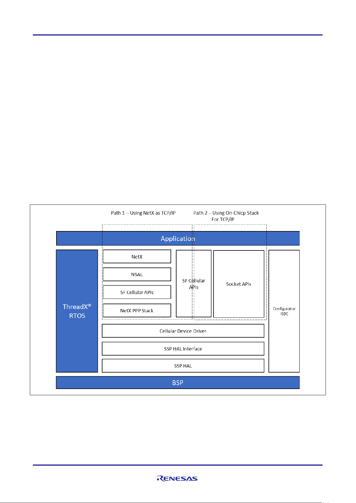
1.1 Major Blocks of the Cellular Framework
The Synergy Cellular Framework consists of the following logical blocks:
• Synergy Cellular Framework Application Interface
• Network Stack Abstraction Layer (NSAL) for NetX TCP/IP stack
• Cellular Device Driver
• BSD Socket compatible APIs for interfacing with Cellular hardware module that supports on-chip
networking stack
• Synergy Software Package (SSP) HAL Interface
Figure 1. Cellular Framework Module Organization and Interface Layers
R30AN0311EU0105 Rev.1.05 Page 3 of 70
Apr.26.19
Page 4

Renesas Synergy™ Platform Cellular Framework
1.1.1 Cellular Framework Application Layer Interface
The Cellular Framework provides a common set of interfaces for the application to configure, provision and
to communicate with the Cellular hardware module. By using these Generic interfaces, the user can develop
the Cellular based application using Synergy MCUs. The Cellular hardware module has various configuration
parameters as specified by the family of 3GPP standards. It is possible that individual device drivers and/or
Cellular chipsets/modules will not support configuration of all parameters. At a bare minimum, the network
operator, Access Point Name (APN) and security credentials are required to make the module functional.
1.1.2 Network Stack Abstraction Layer
The Cellular Framework provides a network stack abstraction layer (NSAL). NSAL is layer which connects
the NetX and the Cellular driver by using (PPP) stack that is used for the data communication over WAN link.
1.1.3 Socket Interface Layer
The Cellular Framework provides a Socket level API for the application to interact with the on-chip
networking stack present on the Cellular hardware module. This requires the Cellular hardware
module/driver to support an on-chip networking stack and socket interface. When the application uses these
APIs, it uses the on-chip networking stack present on the Cellular hardware module and does not use the
NSAL or the NetX and its Socket APIs and does not use the Networking stack running on the Synergy MCU
Group.
1.1.4 PPP Stack
Point to point protocol (PPP) is widely used WAN protocol in the Data communication. NetX provides the
PPP stack support as part of the SSP. NSAL leverages the PPP stack to communicate over the serial
interface to the cellular service provider’s network. PPP provides options that handles authentication
methods like PAP/CHAP. Although these authentication mechanisms are optional, NSAL makes use of
framework APIs to send/receive data from the Cellular hardware module. NSAL allows the cellular device
driver to be re-used without any changes specific to the network stack.
1.1.5 Cellular Device Driver
Cellular Framework uses the AT command set to interact with the Cellular modem using the serial driver.
The serial interface used to interact with the modem is UART. The UART speed used in the framework
defaults are up to 115200bits/sec.
2. Cellular Framework Module Operational Overview
Figure 1 shows the user application perspective, in which the application can be used in two different paths
for the communication using the framework depending on the support available on the Cellular modems.
Some modules provide options to use the TCP/IP stack at the Host end and other modules provide options
to use the TCP/IP stack present on the Cellular modem itself. In some cases, cellular hardware module
provides both. When the host TCP/IP stack (NetX) is used, the logical layers of NetX, NSAL, PPP are used
as described in the Architecture diagram. When the on-chip stack is used, the Socket APIs are used to
communicate with the TCP/IP stack present on the Cellular modem. However, the user cannot use both at
the same time.
R30AN0311EU0105 Rev.1.05 Page 4 of 70
Apr.26.19
Page 5
Renesas Synergy™ Platform Cellular Framework
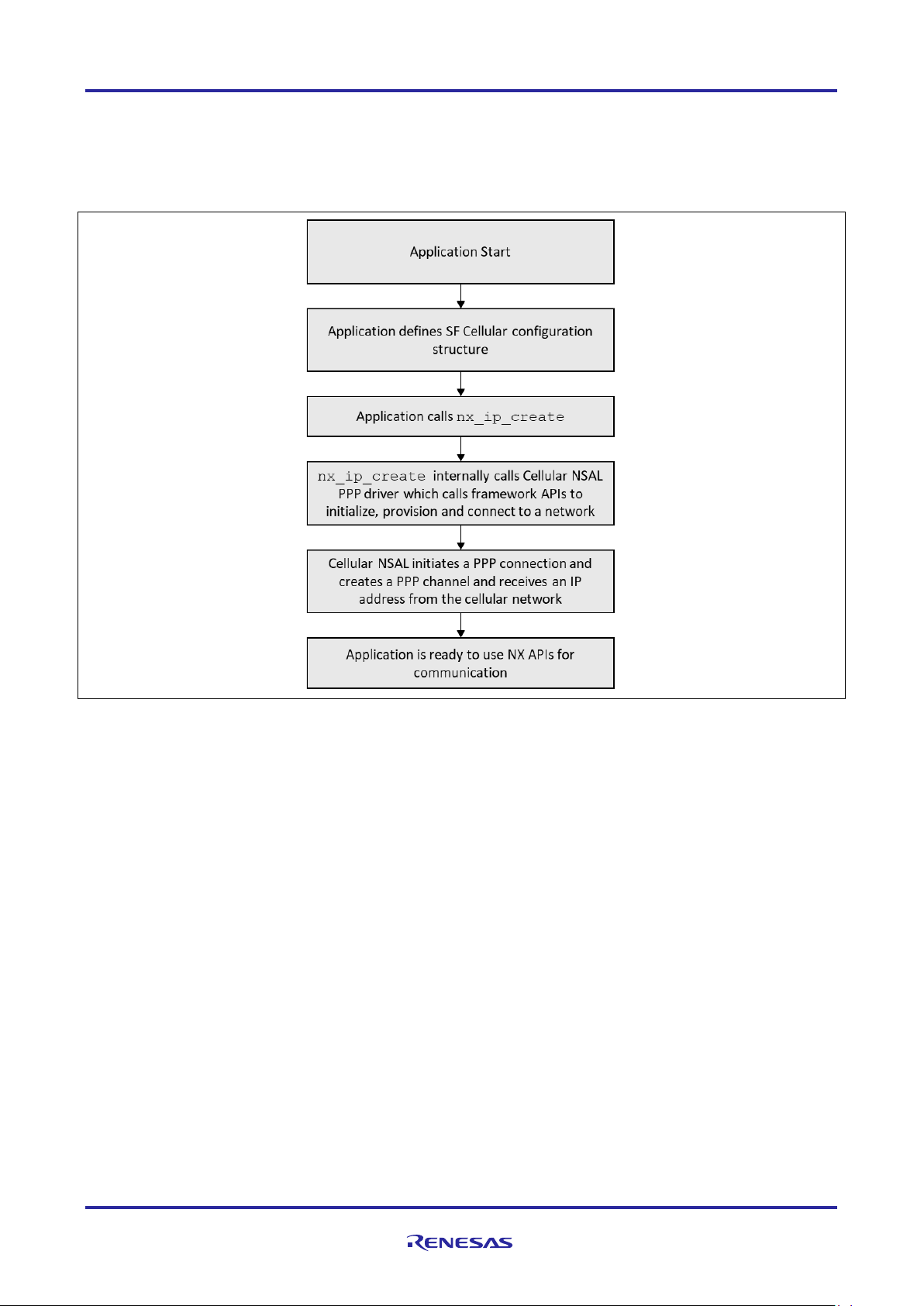
2.1 Cellular Framework Module Initialization
As shown below in the control flow diagram, during the initialization using the configuration supplied by the
user as required for the Cellular modem, NetX nx_ip_create is called that internally invokes the NSAL
driver entry function that takes care of the link level initialization and initializes the cellular hardware module.
In addition, it provisions the module and establishes the Network connection using the PPP interface.
Figure 2. Cellular Framework Module Initialization Sequence
2.2 Cell ul ar Hardware Module Provisioning
Provisioning of the part of the provisioning structure. The arguments used for provisioning is done using the
control structure and the user configured parameter as the provision of the Cellular modem are the
authentication, APN, username and password. In the case of the Cellular Framework, the callback function
provisions the module. You are required to give the APN name, Authentication type and other details
required for provisioning of the module.
R30AN0311EU0105 Rev.1.05 Page 5 of 70
Apr.26.19
Page 6
Renesas Synergy™ Platform Cellular Framework
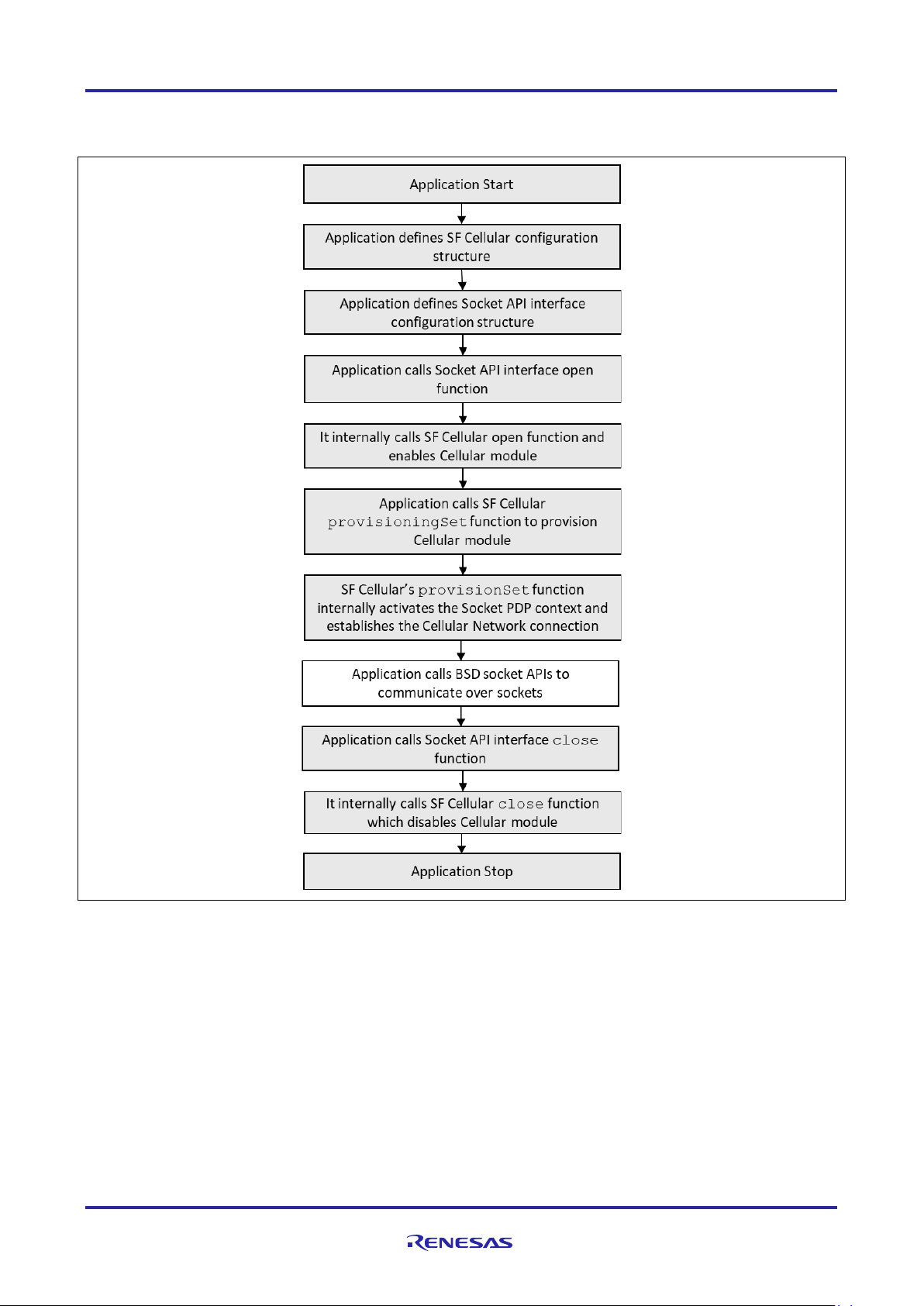
2.3 Application Flow Control Using Socket Interface
The following diagram shows the flow for the on-chip stack path usage with the Cellular Socket interface.
Figure 3. Cellular Framework Module Socket Interface
R30AN0311EU0105 Rev.1.05 Page 6 of 70
Apr.26.19
Page 7
Renesas Synergy™ Platform Cellular Framework
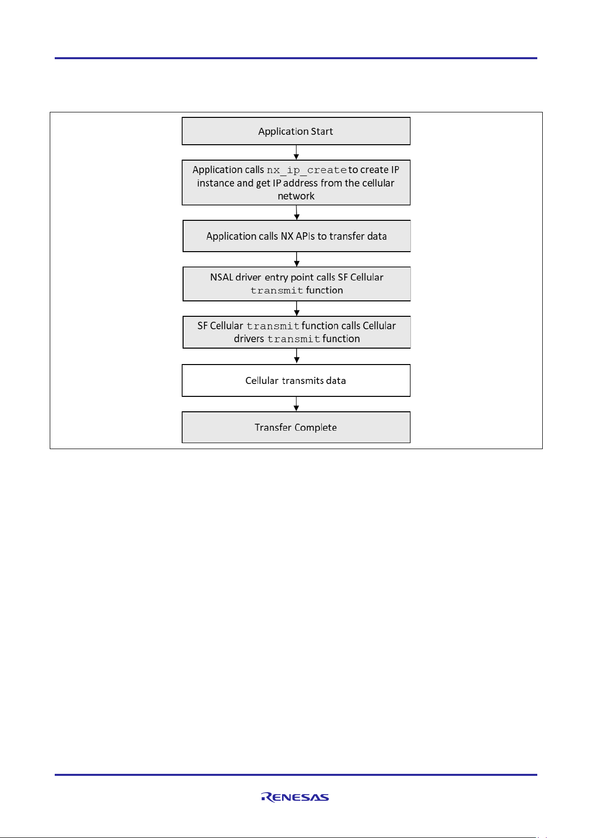
2.4 Cellular Packet Transmission
The following flow diagram shows the sequence of steps that the Packet transmission uses for the NetX
application.
Figure 4. Cellular Framework Packet Transmission Sequence
R30AN0311EU0105 Rev.1.05 Page 7 of 70
Apr.26.19
Page 8
Renesas Synergy™ Platform Cellular Framework
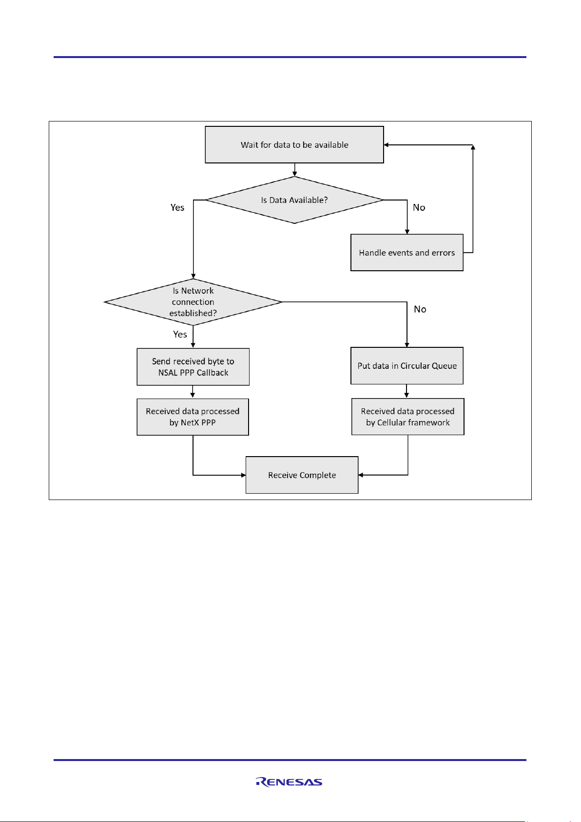
2.5 Cellular Packet Reception
The flow diagram in the below, shows the Packet reception for the Cellular Framework using NetX. In the
case of receive when the data is received on the serial interface, the processing thread triggers the callback
function and the callback functions handles the data and sends it to the NetX layers for further processing.
Figure 5. Cellular Framework Packet Reception Sequence
2.6 Cellular Framework Module Important Operational Notes and Limitations
• The current framework supports the NimbeLink CAT3, CAT1 and Quectel BG96 Cellular hardware
module only.
• Firmware upgrade over air (FOTA) is not supported by NimbeLink CAT3 and CAT1 Cellular hardware
module.
Refer to the latest SSP Release Notes for any additional operational limitations for this module.
3. Cellular Framework Module APIs Overview
The Cellular Framework module defines a set of APIs for interacting with the underlying modules using the
generic interface. The following are the APIs used by the Cellular framework to communicate with the driver
and cellular hardware module. Most of the Cellular framework APIs uses the p_ctrl and p_cfg data
structures as part of the API that are created when the instance is created. For quick and better
understanding of the API, the structure and some of its details are explained here. For more information on
the instance structure refer the SSP User Manual.
R30AN0311EU0105 Rev.1.05 Page 8 of 70
Apr.26.19
Page 9

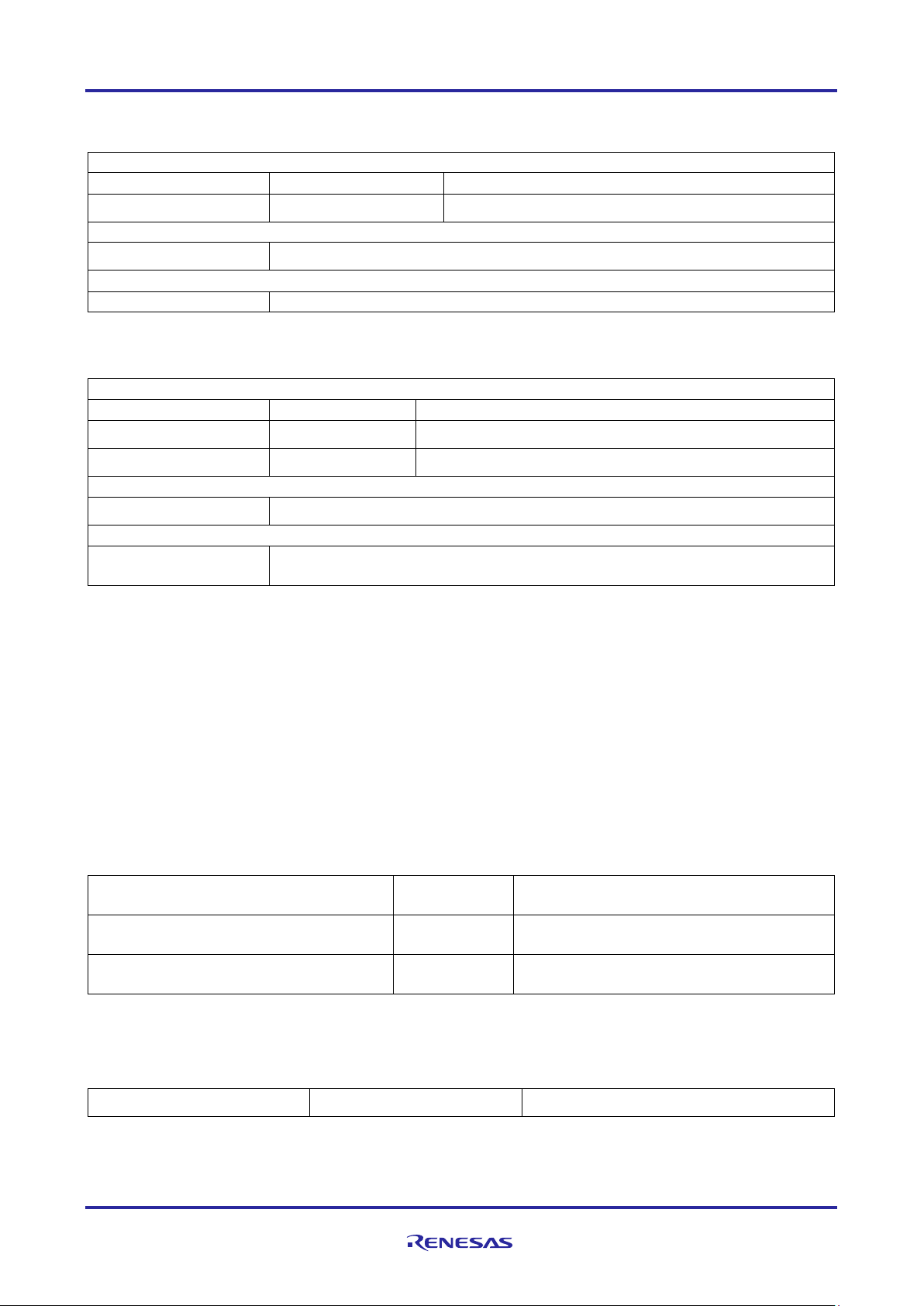
Renesas Synergy™ Platform Cellular Framework
sf_cellular_ctrl_t
* p_ctrl;
Pointer to the control structure for the Cellular framework
instance
sf_cellular_cfg_t
const *
p_cfg;
Pointer to the config structure for the cellular framework
instance
sf_cellular_api_t
const *
p_api;
Pointer to the API structure for the cellular framework
sf_cellular_op_select_mo
op_select_mode
Cellular Operator selection mode. There
automatic)
sf_cellular_op_t
op
Cellular operator. Valid when operator
the name format.
uint16_t
num_pref_ops
Number of preferred cellular operators in
preferred Operator list
sf_cellular_op_t
pref_ops
COUNT]
Array of structures describing preferred
sf_cellular_timezone_upd
tz_upd_mode
TimeZone update mode policy. This is the
update(enable/disable)
uint8_t
* p_sim_pin
SIM Pin. If the SIM has Pin which is
here
uint8_t
* p_puk_pin
PUK Pin. Personal Unlocking Key (PUK),
of PIN protection.
ssp_err_t
(* p_prov_callback)
ck_args_t * p_args)
Pointer to provisioning callback function,
This instance structure encompasses everything that is needed to use an instance for the Cellular framework
interface. Most of the API uses the control and config structure as parameters when it is used from the
application.
typedef struct st_sf_cellular_instance
{
instance
} sf_cellular_instance_t;
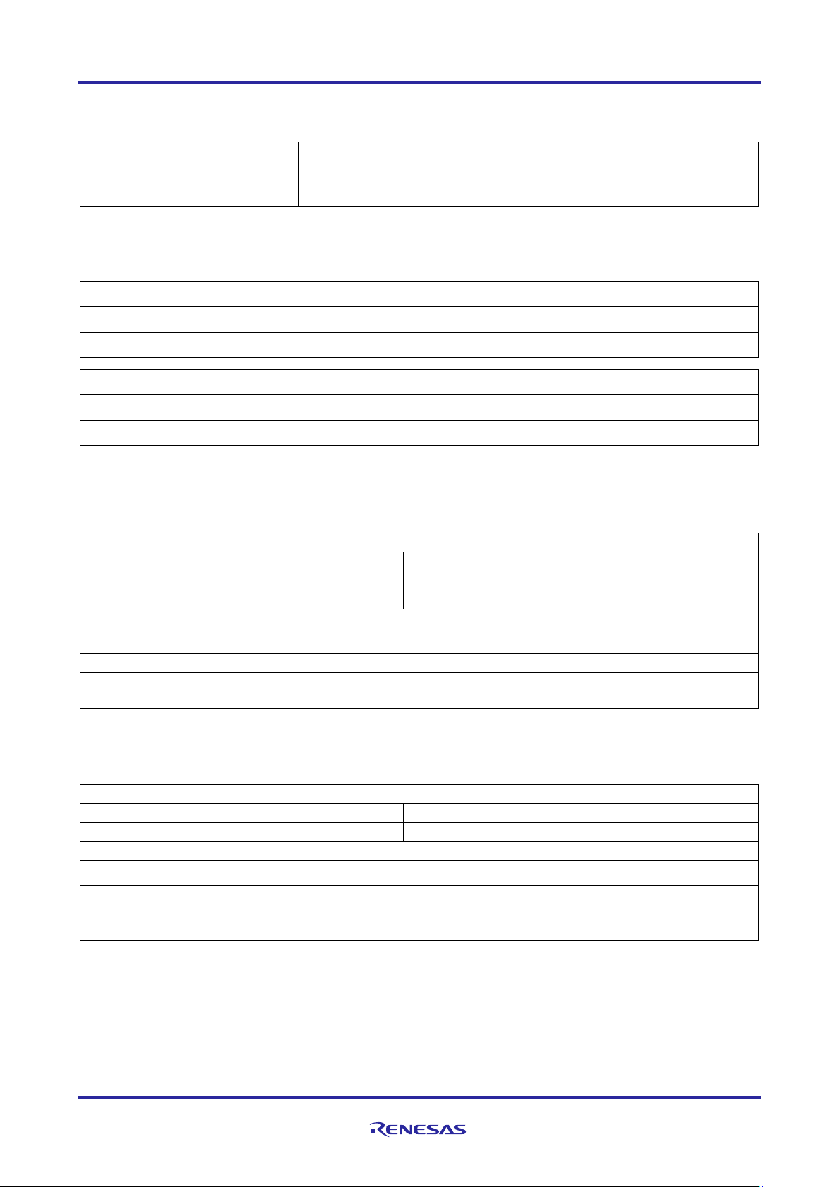
The following structure shows the Cellular configuration parameters that are part of the configuration
structure. Some of these parameters are configured via the configurator. This config information is used by
the underlying drivers when the API’s are called.
typedef struct st_sf_cellular_cfg
{
de_t
ate_mode_t
[SF_CELLULAR_MAX_
PREFFERED_OPERATOR_
are 4 different options available for the
operation mode selection.
Auto (Automatic Operator Selection)
Manual (Manual Operator Selection)
De-register (De-register from the network)
Manual Fallback (Manual with fallback to
selection mode is manual mode. This is
structure within the config structure that
keeps the Cellular Operator Name and
the pref_ops array. User can have
operators
option for automatic time zone
required to unlock, it can be configured
(sf_cellular_callba
R30AN0311EU0105 Rev.1.05 Page 9 of 70
Apr.26.19
is used in 3GPP mobile phones to reset
a personal identification number (PIN) that
has been lost or forgotten. Most Cellular
Modems offer the feature
used in NSAL
Page 10
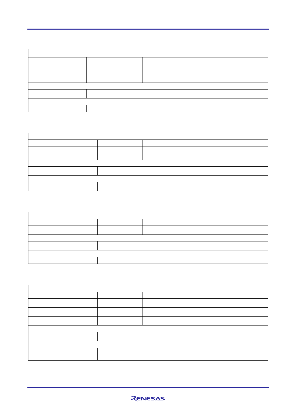
Renesas Synergy™ Platform Cellular Framework
void
(* p_recv_callback)
This is the receive callback function used
void
const * p_context
User defined context passed into callback
function
void
const * p_extend
Instance specific configuration for any
sf_cellular_at_cmd_set_t
const * p_cmd_set
Pointer to Instance specific AT command
set
void
* p_driver_handle
Stores information required by underlying Cellular
device driver.
uint8_t
Apn
[SF_CELLULAR_MAX_STRING_LEN]
Access Point Name
sf_cellular_auth_type_t
auth_type
Authentication type:
PAP/CHAP
uint8_t
Username
[SF_CELLULAR_MAX_STRING_LEN]
User name used for
uint8_t
Password
[SF_CELLULAR_MAX_STRING_LEN]
Password used for
sf_cellular_airplane_mode_t
airplane_mode
Airplane mode
uint8_t
context_id
Context ID to be used for
connection
sf_cellular_pdp_type_t
pdp_type
PDP Type for Context
uint8_t
mfg_name[SF_CELLULAR_MFG_NAME_LEN]
Manufacturer name
uint8_t
chipset[SF_CELLULAR_CHIPSET_LEN]
Pointer to string showing Cellular
chipset/driver information.
uint8_t
fw_version[SF_CELLULAR_FWVERSION_LEN]
Cellular firmware version
uint8_t
imei[SF_CELLULAR_IMEI_LEN]
IMEI number
uint16_t
rssi
Received signal strength
indication
uint16_t
ber
Bit rate error
(sf_cellular_callba
ck_args_t * p_args)
} sf_cellular_cfg_t
typedef struct st_sf_cellular_ctrl
{
} sf_cellular_ctrl_t
3.1 Cell ul ar provisioning information structure
typedef struct st_sf_cellular_provisioning
{
by NetX which will take a data packet
from the Cellular hardware module and
hand it over to NetX for further processing
extended configuration
} sf_cellular_provisioning_t
3.2 Cell ul ar info structure information
typedef struct st_sf_cellular_info
{
} sf_cellular_info_t
authentication
authentication
R30AN0311EU0105 Rev.1.05 Page 10 of 70
Apr.26.19
Page 11
Renesas Synergy™ Platform Cellular Framework
uint32_t
rx_bytes
Bytes received successfully
uint32_t
tx_bytes
Bytes transmitted successfully
uint32_t
rx_err
Bytes receive errors
uint32_t
tx_err
Bytes transmit errors
uint16_t
country_code
Country code
uint16_t
operator_code
Operator code
uint16_t
rssi
RSSI
uint8_t
cid[SF_CELLULAR_CID_LEN]
Cell ID
uint8_t
imsi[SF_CELLULAR_IMSI_LEN]
IMSI
uint8_t
op_name[SF_CELLULAR_MAX_OPERATOR_NAME_LEN]
Operator name
uint8_t
service_domain
Service Domain
Uint8_t
active_band
Active Band
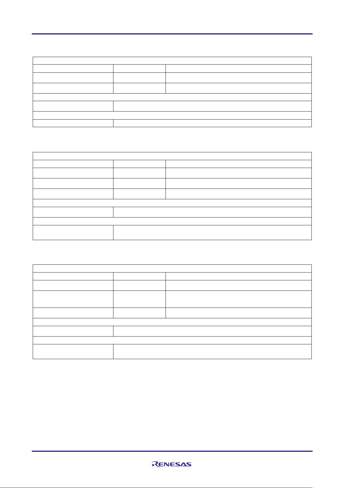
SF_CELLULAR_RESET_TYPE_SOFT
Soft reset module using AT command
SF_CELLULAR_RESET_TYPE_HARD
Hard reset module by toggling Reset Pin
Error Code
Description
SSP_ERR_CELLULAR_CONFIG_FAILED
Cellular module Configuration failed
SSP_ERR_CELLULAR_INIT_FAILED
Cellular module initialization failed.
SSP_ERR_CELLULAR_TRANSMIT_FAILED
Transmission failed
SSP_ERR_CELLULAR_FW_UPTODATE
Firmware is up to date
SSP_ERR_CELLULAR_FW_UPGRADE_FAILED
Firmware upgrade failed
SSP_ERR_CELLULAR_FAILED
Cellular Failed.
3.3 The s ta ti stic and error counters for the cellular instance
typedef struct st_sf_cellular_stats
{
} sf_cellular_stats_t
3.4 The Cellular network status structure
typedef struct st_sf_cellular_network_status
{
} sf_cellular_network_status_t
3.5 Cellular Hardware Module reset type
Typedef enum e_sf_cellular_reset_type
{
} sf_cellular_reset_type_t
Table 1. ssp_err_t (SSP Error Codes):
Note: These are error codes returned by the SSP when the API is used. The table lists error codes specific
to the Cellular framework. For more information and the entire SSP Error codes refer the SSP User
Manual or the (synergy/ssp/inc/ssp_common_api.h).
R30AN0311EU0105 Rev.1.05 Page 11 of 70
Apr.26.19
Page 12
Renesas Synergy™ Platform Cellular Framework
Parameter
Name
Direction
Description
p_ctrl
In
See Table 1
p_cfg
In
See Table 1
Return values
See Table 1
Function Prototype
ssp_err_t (*open) (sf_cellular_ctrl_t * p_ctrl,sf_cellular_cfg_t const * const
p_cfg)
Parameter
Name
Direction
Description
p_ctrl
In
See Table 1
Return values
See Table 1
Function Prototype
ssp_err_t (*close) (sf_cellular_ctrl_t * p_ctrl)
Parameter
Name
Direction
Description
p_ctrl
In
See Table 1
p_cellular_provisioning
Out
See Table 1
Return values
See Table 1
Function Prototype
ssp_err_t (* provisioningGet) (sf_cellular_ctrl_t *
p_cellular_provisioning)
3.6 Cellular Framework API
3.6.1 open
It initializes and enables the Cellular hardware module for data transfers. It does initial driver configuration,
enables the driver link, enables interrupts and makes the device ready for data transfer.
3.6.2 close
Description: It de-initializes and disables the Cellular hardware module for any communication. It deactivates
the PDP context.
Table 1. ssp_err_t (SSP Error Codes):
3.6.3 provisioningGet
Description: It gets the provisioning information for the cellular hardware module
const p_ctrl, sf_cellular_provisioning_t * const
R30AN0311EU0105 Rev.1.05 Page 12 of 70
Apr.26.19
Page 13
Renesas Synergy™ Platform Cellular Framework
Parameter
Name
Direction
Description
p_ctrl
In
See Table 1
p_cellular_provisioning
In
See Table 1
Return values
See Table 1
Function Prototype
ssp_err_t (* provisioningSet) (sf_cellular_ctrl_t *
const p_cellular_provisioning)
Parameter
Name
Direction
Description
p_ctrl
In
See Table 1
p_cellular_info
Out
See Table 1
Return values
See Table 1
Function Prototype
ssp_err_t (* infoGet) (sf_cellular_ctrl_t * const p_ctrl,
sf_cellular_info_t * const p_cellular_info)
Parameter
Name
Direction
Description
p_ctrl
In
See Table 1
p_cellular_device_stats
Out
See Table 1
Return values
See Table 1
Function Prototype
ssp_err_t (* statisticsGet) (sf_cellular_ctrl_t * const
p_cellular_device_stats)
3.6.4 provisioningSet
Description: It sets the provisioning information for the cellular hardware module.
const p_ctrl, sf_cellular_provisioning_t const *
3.6.5 infoGet
Description: It Reads the Cellular hardware module's information.
3.6.6 statisticsGet
Description: It Returns statistics information of Cellular hardware module.
p_ctrl, sf_cellular_stats_t * const
R30AN0311EU0105 Rev.1.05 Page 13 of 70
Apr.26.19
Page 14
Renesas Synergy™ Platform Cellular Framework
Parameter
Name
Direction
Description
p_ctrl
In
See Table 1
p_buf
In
Pointer to packet buffer to transmit
length
In
Length of packet buffer
Return values
See Table 1
Function Prototype
ssp_err_t (* transmit) (sf_cellular_ctrl_t * const p_ctrl,
uint8_t * const p_buf, uint32_t length)
Parameter
Name
Direction
Description
p_version
Out
p_version pointer to memory location to return version
number Gets the version number of API and SSP Code
Return values
See Table 1
Function Prototype
ssp_err_t (* versionGet)(ssp_version_t * const p_version)
Parameter
Name
Direction
Description
p_ctrl
In
See Table 1
Return values
See Table 1
Function Prototype
ssp_err_t (* networkConnect) (sf_cellular_ctrl_t * const p_ctrl)
Parameter
Name
Direction
Description
p_ctrl
In
See Table 1
Return values
See Table 1
Function Prototype
ssp_err_t (* networkDisconnect) (sf_cellular_ctrl_t *
const p_ctrl)
3.6.7 transmit
Description: It passes packet buffer to PPP stack for transmission
3.6.8 versionGet
Description: Gets version and stores it in provided pointer p_version.
3.6.9 networkConnect
Description: Initiates the Data connection
3.6.10 networkDisconnect
Description: Terminates the Data connection
R30AN0311EU0105 Rev.1.05 Page 14 of 70
Apr.26.19
Page 15
Renesas Synergy™ Platform Cellular Framework
Parameter
Name
Direction
Description
p_ctrl
In
See Table 1
p_network_status
Out
See Table 1
Return values
See Table 1
Function Prototype
ssp_err_t (* networkStatusGet) (sf_cellular_ctrl_t * const
p_ctrl, sf_cellular_network_status_t * p_network_status)
Parameter
Name
Direction
Description
p_ctrl
In
See Table 1
p_old_pin
In
Pointer to char array containing current 4-digit pin
p_new_pin
In
Pointer to char array containing new 4-digit pin
Return values
See Table 1
Function Prototype
ssp_err_t (* simPinSet) (sf_cellular_ctrl_t * const
p_new_pin)
Parameter
Name
Direction
Description
p_ctrl
In
See Table 1
p_pin
In
PIN number to lock the SIM
Return values
See Table 1
Function Prototype
ssp_err_t (* simLock) (sf_cellular_ctrl_t * const p_ctrl,
uint8_t * const p_pin)
3.6.11 networkStatusGet
Description: Get Network Status information
3.6.12 simPinSet
Description: Set SIM Pin.
3.6.13 simLock
Description: Locks the SIM.
p_ctrl, uint8_t * const p_old_pin, uint8_t * const
R30AN0311EU0105 Rev.1.05 Page 15 of 70
Apr.26.19
Page 16
Renesas Synergy™ Platform Cellular Framework
Parameter
Name
Direction
Description
p_ctrl
In
See Table 1
p_pin
In
PIN number to unlock the SIM
Return values
See Table 1
Function Prototype
ssp_err_t (* simUnlock) (sf_cellular_ctrl_t * const
p_ctrl, uint8_t * const p_pin)
Parameter
Name
Direction
Description
p_ctrl
In
See Table 1
p_sim_id
Out
SIM ID
Return values
See Table 1
Function Prototype
ssp_err_t (* simIDGet)(sf_cellular_ctrl_t * const p_ctrl,
uint8_t * p_sim_id)
Parameter
Name
Direction
Description
p_ctrl
In
See Table 1
Return values
See Table 1
Function Prototype
ssp_err_t (* fotaCheck) (sf_cellular_ctrl_t * const
p_ctrl)
Parameter
Name
Direction
Description
p_ctrl
In
See Table 1
Return values
See Table 1
Function Prototype
ssp_err_t (* fotaStart) (sf_cellular_ctrl_t * const
p_ctrl)
3.6.14 simUnlock
Description: Unlocks the SIM.
3.6.15 simIDGet
Description: Gets the SIM ID
3.6.16 fotaCheck
Description: Checks for Available Firmware upgrade
3.6.17 fotaStart
Description: Starts the Firmware upgrade
R30AN0311EU0105 Rev.1.05 Page 16 of 70
Apr.26.19
Page 17
Renesas Synergy™ Platform Cellular Framework
Parameter
Name
Direction
Description
p_ctrl
In
See Table 1
Return values
See Table 1
Function Prototype
ssp_err_t (* fotaStop) (sf_cellular_ctrl_t * const p_ctrl)
Parameter
Name
Direction
Description
p_ctrl
In
See Table 1
reset_type
In
Reset Type
Return values
See Table 1
Function Prototype
ssp_err_t (* reset) (sf_cellular_ctrl_t * const p_ctrl,
sf_cellular_reset_type_t reset_type))
sf_cellular_onchip_stack_ctrl_t
* p_ctrl
Pointer to the control structure for the
Cellular framework instance
sf_cellular_onchip_stack_cfg_t
const *
p_cfg
Pointer to the config structure for the cellular
framework instance
sf_cellular_onchip_stack_api_t
const *
p_api
Pointer to the API structure for the cellular
sf_cellular_instance_t
*p_lower_lvl_cellular
Pointer to SF Cellular instance
3.6.18 fotaStop
Description: Stops the Firmware upgrade
3.6.19 reset
Reset cellular hardware module
3.7 Cellular Framework Socket Interface API
The Cellular Framework module provides a set of APIs for interacting with the Cellular hardware modules
that have an on-chip stack using the socket interface. The following are the APIs used by the Cellular
Framework to communicate with the on-chip stack on the Cellular hardware module. Framework provides
two sets of APIs to communicate with the on-chip module. The first set of APIs uses the p_ctrl and p_cfg
data structures as part of the API which are created when the instance is created. The second set of APIs
are the socket interface to create TCP/UDP sockets for data communications. For a quick and better
understanding of the API, the structure and its details are explained in the SSP User Manual.
This instance structure encompasses everything that is needed to use an instance for the Cellular framework
interface.
typedef struct st_sf_cellular_onchip_stack_instance
{
} sf_cellular_onchip_stack_instance_t;
typedef struct st_sf_cellular_onchip_stack_ctrl
framework instance
{
} sf_cellular_onchip_stack_ctrl_t
Defines the Cellular configuration parameters
R30AN0311EU0105 Rev.1.05 Page 17 of 70
Apr.26.19
Page 18
Renesas Synergy™ Platform Cellular Framework
sf_cellular_instance_t
const *
p_lower_lvl
Pointer to SF Cellular instance
void
* p_extend
Extended configuration
SF_CELLULAR_CAT3_SOCKET_INVALID_FD
(-1)
Invalid Socket Descriptor
SF_CELLULAR_CAT3_SOCKET_ERROR
(-1)
Error processing Socket API.
SF_CELLULAR_CAT3_SOCKET_SUCCESS
(0)
Socket Success
SF_CELLULAR_CAT1_SOCKET_INVALID_FD
(-1)
Invalid Socket Descriptor
SF_CELLULAR_CAT1_SOCKET_ERROR
(-1)
Error processing Socket API.
SF_CELLULAR_CAT1_SOCKET_SUCCESS
(0)
Socket Success
Parameter
Name
Direction
Description
p_ctrl
In
See Table 1
p_cfg
In
See Table 1
Return values
See Table 1
Function Prototype
ssp_err_t (* open) (sf_cellular_socket_ctrl_t * p_ctrl,
sf_cellular_socket_cfg_t const * const p_cfg)
Parameter
Name
Direction
Description
p_ctrl
In
See Table 1
Return values
See Table 1
Function Prototype
ssp_err_t (* close) (sf_cellular_socket_ctrl_t * const
p_ctrl)
typedef struct st_sf_cellular_onchip_stack_cfg
{
} sf_cellular_onchip_stack_cfg_t;
Table 2. On-chip socket API error codes for CAT3 and CAT1
3.7.1 open
Description: It initializes and enables the Cellular hardware module for data transfers. It does initial driver
configuration, enable the driver link, enable interrupts and makes the device ready for data transfer.
3.7.2 close
Description: Pointer to function which un-initialize the network interface and may put it in low power mode or
power it off. Close the driver, disables the driver link, disable interrupt.
R30AN0311EU0105 Rev.1.05 Page 18 of 70
Apr.26.19
Page 19
Renesas Synergy™ Platform Cellular Framework
Parameter
Name
Direction
Description
p_version
Out
p_version pointer to memory location to return version
Code
Return values
See Table 1
Function Prototype
ssp_err_t (* versionGet) (ssp_version_t * const p_version)
Parameter
Name
Direction
Description
p_ctrl
In
See Table 2
p_cfg
In
See Table 2
Return values
See Table 2
Function Prototype
int socket (int domain, int type, int protocol)
Parameter
Name
Direction
Description
socket_fd
In
Local socket
Return values
See Table 2
Function Prototype
int close (int socket_fd)
Parameter
Name
Direction
Description
socket_fd
In
Local socket
p_local_sock_addr
In
Pointer to local socket address
addrlen
In
Size of sock address structure
Return values
See Table 2
Function Prototype
int bind (int socket_fd, const struct sockaddr *
p_local_sock_addr, socklen_t addrlen)
3.7.3 versionGet
Description: Gets version and stores it in provided pointer p_version.
number Gets the version number of API and SSP
3.7.4 socket
Description: This API creates the socket.
3.7.5 close
Description: This API closes the socket.
3.7.6 bind
Description: This API Bind socket to interface which is identified by IP address
R30AN0311EU0105 Rev.1.05 Page 19 of 70
Apr.26.19
Page 20
Renesas Synergy™ Platform Cellular Framework
Parameter
Name
Direction
Description
socket_fd
In
Local socket
backlog
In
Max number of connection queue
Return values
See Table 2
Function Prototype
int listen (int sockfd, int backlog)
Parameter
Name
Direction
Description
socket_fd
In
Local socket
p_local_sock_addr
In
Pointer to local socket address
addrlen
In
Size of sock address structure
Return values
See Table 2
Function Prototype
int connect (int sockfd, const struct sockaddr *
p_serv_addr, socklen_t addrlen)
Parameter
Name
Direction
Description
sockfd
In
Local socket
p_cliaddr
Out
Pointer to remote socket address which trying to
p_addrlen
Out
Pointer to address length of client socket address
Return values
See Table 2
Function Prototype
int accept (int sockfd, struct sockaddr * p_cliaddr,
socklen_t * p_addrlen)
3.7.7 listen
Description: Listen for TCP connection. Set socket in listen mode for TCP connection
3.7.8 connect
Description: Establish TCP connection with remote socket.
3.7.9 accept
Description: Accept connection request from remote.
connect
R30AN0311EU0105 Rev.1.05 Page 20 of 70
Apr.26.19
Page 21
Renesas Synergy™ Platform Cellular Framework
Parameter
Name
Direction
Description
sockfd
In
Local socket
p_buf
In
Pointer to Data buffer
length
In
Data buffer length
flags
In
Socket flags
Return values
On success, these calls return the number of characters sent. On error, -1
Function Prototype
ssize_t send(int sockfd, const void * p_buf, size_t
length, int flags)
Parameter
Name
Direction
Description
sockfd
In
Local socket
p_buf
Out
Pointer to Data buffer where data will be received
length
In
Maximum length of data which can be received
flags
In
Socket flags
Return values
On success, these calls return the number of characters received. On error,
Function Prototype
ssize_t recv (int sockfd, void * p_buf, size_t length,
int flags)
3.7.10 send
Description: Send data to remote socket.
is returned
3.7.11 recv
Description: Receive data from remote socket.
-1 is returned
R30AN0311EU0105 Rev.1.05 Page 21 of 70
Apr.26.19
Page 22
Renesas Synergy™ Platform Cellular Framework
Parameter
Name
Direction
Description
sock_fd
In
Local socket
p_buf
Out
Pointer to Data buffer to sent
length
In
Data Buffer length
flags
In
Socket flags
p_dest_addr
In
Pointer to remote socket address where to send data
addrlen
In
Length of the Socket address structure
Return values
On success, these calls return the number of characters sent. On error, -1
Function Prototype
ssize_t sendto (int sockfd, const void * p_buf, size_t
socklen_t addrlen)
Parameter
Name
Direction
Description
sockfd
In
Local socket
p_buf
Out
Pointer to Data buffer where data will be received
length
In
Maximum length of data which can be received
flags
In
Socket flags
p_dest_addr
In
Pointer to remote socket address which has sent data
addrlen
In
Length of the Socket address structure
Return values
On success, these calls return the number of characters received. On error,
Function Prototype
ssize_t recvfrom (int sockfd, void * p_buf, size_t
socklen_t * p_addrlen)
3.7.12 sendto
Description: Send data to remote socket.
is returned
length, int flags, const struct sockaddr * p_dest_addr,
3.7.13 recvfrom
Description: Receive data from remote socket.
-1 is returned
length, int flags, struct sockaddr * p_src_addr,
R30AN0311EU0105 Rev.1.05 Page 22 of 70
Apr.26.19
Page 23

Renesas Synergy™ Platform Cellular Framework
Parameter
Name
Direction
Description
sockfd
In
Local socket
level
In
Sockets API level
optname
In
Options to be set
p_optval
In
Options value to be set
optlen
In
Length of the option value
Return values
See Table 2
Function Prototype
int setsockopt (int sockfd, int level, int optname, const
void * p_optval, socklen_t optlen)
Parameter
Name
Direction
Description
sockfd
In
Local socket
level
In
Sockets API level
optname
In
Options to be get
p_optval
Out
Options value to be get
optlen
In
Length of the option value
Return values
See Table 2
Function Prototype
int getsockopt (int sockfd, int level, int optname, void *
p_optval, socklen_t * p_optlen)
3.7.14 setsockopt
Description: Set Socket options
3.7.15 getsockopt
Description: Get Socket options
R30AN0311EU0105 Rev.1.05 Page 23 of 70
Apr.26.19
Page 24

Renesas Synergy™ Platform Cellular Framework
Parameter
Name
Direction
Description
nfds
In
Max fd
p_readfds
In
Pointer to fd_set to check whether data is available for read
p_writefds
In
Pointer to fd_set to check whether data is available for write
p_exceptfds
In
Pointer to fd_set to check whether exceptional condition occurred
p_timeout
In
Wait time in milliseconds
Return values
See-Table 2
Function Prototype
int select (int nfds, fd_set * p_readfds, fd_set *
p_timeout);
Resource
ISDE Tab
Stacks Selection Sequence
g_sf_cellular_nx0(NetX
Threads
From the included NetX application (HTTP Client) Add
3.7.16 select
Description: Wait on a given socket for specified amount of time. In case of any activity or arrival of packet
that comes out of wait.
p_writefds, fd_set * p_exceptfds, struct timeval *
Note: For details on operation and definitions for the function data structures, typedefs, defines, API data,
API structures, and function variables, review the SSP User’s Manual, API References for the
associated module.
4. Including the Cellular Framework Module in an Application
This section describes how to include the Cellular Framework module in an application using the ISDE
configurator.
Note: It is assumed that you are familiar with creating a project, adding threads, adding a stack to a thread,
and configuring a block within the stack. If you are unfamiliar with any of these items, refer to the first
few chapters of the SSP User’s Manual to learn how to manage each of these important steps in
creating SSP-based applications.
To add the Cellular Framework to an application, simply add it to a thread using the stacks selection
sequence given in the following table. Cellular framework Supports following options to add the framework to
the application. Based on where the TCP/IP stack loaded and running on the module it can be classified as
follows:
• Cellular framework using NetX as TCP/IP stack (TCP/IP stack running on Synergy Host).
• Cellular framework using On-chip stack (TCP/IP stack present on Cellular Hardware Module).
4.1 Incl uding the Cellular Framework Module with NetX as TCP/IP Stack
When the Cellular framework is used with NetX, it can be included using three different ways as follows:
• Including the Cellular framework with just NetX Port (NSAL Layer).
• Including the Cellular framework along with IP instance to the application
• Including the Cellular framework along with NetX application layers.
Table 3. Including Cellular Framework Module with the NetX Port
Port using Cellular
framework)
R30AN0311EU0105 Rev.1.05 Page 24 of 70
Apr.26.19
NetX Network Driver->New->NetX Port using Cellular
Framework on sf_cellular_nsal_nx
Page 25

Renesas Synergy™ Platform Cellular Framework
Resource
ISDE Tab
Stacks Selection Sequence
g_ip0(NetX IP Instance)
Threads
X-Ware->NetX->NetX IP instance
Resource
ISDE Tab
Stacks Selection Sequence
g_sf_cellular_nx0(NetX
framework)
Threads
From the included (IP instance) Add NetX Network
sf_cellular_nsal_nx
Figure 6. Cellular Framework Module using NetX Port
Table 4. Including Cellular Framework Module with the NetX IP Instance
Figure 7. Including the Cellular Framework Module with NetX IP Instance
Table 5. Including the Cellular Framework with the NetX IP Instance
Port using Cellular
Driver->New->NetX Port using Cellular Framework on
R30AN0311EU0105 Rev.1.05 Page 25 of 70
Apr.26.19
Page 26

Renesas Synergy™ Platform Cellular Framework
Resource
ISDE Tab
Stacks Selection Sequence
g_http_client0(NetX http Client)
Threads
X-ware->Protocols->NetX HTTP Client
Figure 8. Including Cellular Framework NSAL Layer
In some applications, it is required to include the Cellular framework along with NetX application layer or with
an IP instance like (Synergy Wi-Fi and Ethernet applications). The sequence and sample snapshot of
including HTTP client sequence is shown as follows.
Table 6. NetX HTTP Module Selection Sequence
Figure 9. NetX Application HTTP Client Inclusion
R30AN0311EU0105 Rev.1.05 Page 26 of 70
Apr.26.19
Page 27

Renesas Synergy™ Platform Cellular Framework
Resource
ISDE Tab
Stacks Selection Sequence
g_sf_cellular_nx0(NetX
framework)
Threads
From the included NetX application (HTTP Client) Add
Framework on sf_cellular_nsal_nx
Resource
ISDE Tab
Stacks Selection Sequence
g_sf_cellular_socket0(BSD Socket
Cellular framework)
Threads
Framework->Networking->Cellular-> BSD So c ket
Table 7. Cellular Framework Module Selection Sequence with NetX Stack
Port using Cellular
NetX Network Driver->New->NetX Port using Cellular
Figure 10. NSAL Layer Included with NetX Application Layer
4.2 Incl uding the Cellular Framework Module with On-chip Stack for TCP /IP
In some applications, it is required to include the Cellular framework with On-chip TCP/IP stack, which is
present on the cellular hardware module itself. When the stack running on the Cellular hardware module is
used, the NetX stack will not be used on the Synergy host. The sequence and sample snapshot of including
Cellular framework along with On-Chip stack support sequence is shown as follows.
Table 8. Cellular Framework Module Selection Sequence for CAT3 with On-chip Stack
using On-chip stack using CAT3
using On-Chip Stack on CAT3 Cellular Framework
R30AN0311EU0105 Rev.1.05 Page 27 of 70
Apr.26.19
Page 28

Renesas Synergy™ Platform Cellular Framework
Resource
ISDE Tab
Stacks Selection Sequence
g_sf_cellular_socket0(BSD Socket
Cellular framework)
Threads
Framework->Networking->Cellular-> BSD So c ket
Figure 11. Cellular Framework Module using On-chip Stack for CAT3
Table 9. Cellular Framework Module Selection Sequence for CAT1 with On-chip Stack
using On-chip stack using CAT1
Figure 12. Cellular Framework Module using On-chip Stack for CAT1
using On-Chip Stack on CAT1 Cellular Framework
R30AN0311EU0105 Rev.1.05 Page 28 of 70
Apr.26.19
Page 29

Renesas Synergy™ Platform Cellular Framework
ISDE Property
Default Value
Description
Common
Parameter Checking
BSP, Enabled, Disabled
These are the optional SSP feature
additional checking in the SSP code.
g_sf_el_nx0 NetX Port using Cellul ar Framework on sf_cellular_nsal_nx
Name
g_sf_el_nx0
Name of the NetX Port instance
PPP Stack Size in Bytes
2048
This is the stack size for the PPP. By
size as 2048.
Name
g_nx_ppp0
Name of the PPP instance
Numerical priority of PPP Thread
3
This is the priority of the internal PPP
priority.
5. Configuring the Cellular Framework Module
In the previous section, different ways to include the Cellular framework to the application is described. In
this section configuring the framework modules and its dependency modules are explained. The details of
individual configuration parameter, its recommended value, default value along with the descriptions are
given so that the user can use them as applicable in their applications.
5.1 Configuring Cellular Framework with NetX as TCP/IP Stack
Figure 13. Cellular Framework Module using NetX as TCP/IP Stack
The configuration property for g_sf_el_nx0 NetX Por t using Ce llular framework on
sf_cellular_nsal_nx is described as follows.
Default: BSP
(Priority must be lower than IP
Helper thread). Legal values range
from 0 through
(TX_MAX_PRIORITES-1), where a
which checks for the parameter passed
from API in the SSP code. User can
disable this if application does not need
default, it is set to 2048. User needs to
keep this value for optimal operation.
User need to keep the minimal stack
thread used in the framework. Users are
advised to keep the application thread at
the same level as this priority. Or the
application thread can be in the low
R30AN0311EU0105 Rev.1.05 Page 29 of 70
Apr.26.19
Page 30

Renesas Synergy™ Platform Cellular Framework
ISDE Property
Default Value
Description
Common
value of 0 represents the highest
priority.
Authentication Method
None
This is the field for selecting the
authentication.
Invalid Packet Handler Callback
NULL
This is the Callback for the Invalid
Callback to handle the Invalid Packet.
PAP Login Callback
ppp_link_down_callback
This is the Callback provided by
interface. Or take appropriate action.
PAP Verify Login Callback
ppp_link_up_callback
This is the Callback provided by
as per the application requirement
Get Challenge Values Callback
NULL
This is the callback for the
Get Responder Values Callbac k
NULL
This is the callback for the
Responder values.
Get Verification Callback
NULL
This is the callback for the
Verification.
Local IPv4 Address (use commas
0,0,0,0
PPP is point to point protocol, this is the
address) if 0,0,0,0 is chosen in this field.
Peer IPv4 Address (use commas
0,0,0,0
This is the placeholder for the user to
then it can be assigned here.
ISDE Property
Default Value
Description
Module NetX PPP Common
Name
g_nx_ppp_common0
Name of the PPP Common Module
Authentication for the PPP. PPP works
with PAP or CHAP or None
Packet handling. User can have the
Framework, User can customize the
callback to handle the PPP link down
event in their respective applications.
For example, when the PPP link goes
down, application can switchover to
available network communication
Framework, User can customize the
callback to handle the PPP link up event.
User can customize the callback handle
for separation)
for separation)
Authentication CHAP. If the user wishes
to use the CHAP authentication, the
callback needs to code to handle the
Challenge values.
Authentication CHAP. If the user wishes
to use the CHAP authentication, the
callback needs to code to handle the
Authentication CHAP. If the user wishes
to use the CHAP authentication, the
callback needs to code to handle the
place where the Local IP address is
configured. But PPP also gives the
option where peer side (assigns the IPv4
assign the IP address of the peer. In the
case, Cellular framework if the predefined IP address is given from the
service provider to use for the PPP link,
The configuration property for NetX PPP Common is described as follows. This module gets added and user
is not required to make any changes to the configuration.
R30AN0311EU0105 Rev.1.05 Page 30 of 70
Apr.26.19
Page 31

Renesas Synergy™ Platform Cellular Framework
ISDE Property
Default Value
Description
Common
Parameter Checking
BSP, Enabled, Disabled
These are the optional SSP feature
the SSP code.
On-Chip Stack Support
Enabled, Disabled
These options are used for the
disabled
Modem
For CAT3 - TVSG, TEUG
These are the Modem Selections
CAT3 modems are used.
g_sf_cellular0 Cellular Framework on CAT3 / CAT1 Modem
Name
g_sf_cellular0
Instance name for the Cellular Modem
SIM Pin (Used to Unlock SIM)
1111
SIM Pin for unlocking the SIM, If the
configured here.
SIM PUK Pin (Used to Unlock SIM)
12345678
Sim Personal Unlocking Key to unlock
this can be configured here.
Number of Preferred Operator
0
Total Number of preferred operators. If
based the sequence from 1 to 5
Preferred Operator 1 Name
40422
Numerical Name for the Operator 1
Preferred Operator 1 Name Format
Numeric
Name format of the Operator
Preferred Operator 2 Name
40422
Numerical Name for the Operator 2
Preferred Operator 2 Name Format
Numeric
Name format of the Operator
Preferred Operator 3 Name
40424
Numerical Name for the Operator 3
Preferred Operator 3 Name Format
Numeric
Name format of the Operator
Preferred Operator 4 Name
40422
Numerical Name for the Operator 4
Preferred Operator 4 Name Format
Numeric
Name format of the Operator
Preferred Operator 5 Name
40424
Numerical Name for the Operator 5
Preferred Operator 5 Name Format
Numeric
Name format of the Operator
Operator Select Mode
Auto
Operator selection mode Auto or
Manual
Operator Name (Manual Mode
Selection)
40422
Operator name in Numerical for the
manual mode
Operator Name Format (Manual
Mode Selection)
Numeric
Operator Name format for the Manual
Mode
Time Zone Update Policy
Enabled
Time synchronization from the Network
Receive Data Callback
sf_cellular_nsal_recv_cal
lback
Callback function the receiver
5.1.1 Cellular Framework Module CAT3 / CAT1 and CATM1 Modem Device Driver
Configuration
The configuration property for g_sf_cellular0 Cellular Framework on CAT3 Modem is described as
follows. In this module, the configuration specific to the modem and its interface to the Framework.
Default: BSP
Default: Disabled
For CAT1 - GELS3,
WM14
which checks for the parameter
passed from API in the SSP code.
User can disable this if application
does not need additional checking in
selection of the On-Chip stack. When
NetX Stack is used this should be
based on the CAT3 and CAT1
Modules used in the Applications. For
different regions (Such as North
America, Europe) based on the LTE
band, different flavors of the CAT1 or
SIM needs unlocking this can be
the SIM. If the SIM needs unlocking
R30AN0311EU0105 Rev.1.05 Page 31 of 70
Apr.26.19
non-zero, the modem will try Operator
Page 32

Renesas Synergy™ Platform Cellular Framework
ISDE Property
Default Value
Description
Provisioning Callback
celr_prov_callback
Callback function for the provisioning
the Cellular hardware module
Circular Queue Size in Bytes
256
Data Queue size in bytes for the
SF Communication Framework
512
Stack size for the internal
stack size required is 512 Bytes
Numerical priority of SF
5
Priority of the Communication
Cellular Hardware Module Reset IO
Pin
IOPORT_PORT_10_PIN
_05
GPIO Pin which is used as Reset Pin
ISDE Property
Default Value
Description
Common
Parameter Checking
BSP, Enabled, Disabled
These are the optional SSP feature
additional checking in the SSP code.
On-Chip Stack Support
Enabled, Disabled
These options are used for the selection
is used this should be disabled
AT Command Retry Count
5
No of times to retry with AT Command
g_sf_cellular0 Cellular Framework on CATM1 Modem
Name
g_sf_cellular0
Instance name for the Cellular Modem
SIM Pin (Used to Unlock SIM)
1111
SIM Pin for unlocking the SIM, If the
configured here.
SIM PUK Pi n (Used to Unlock
12345678
Sim Personal Unlocking Key to unlock
can be configured here.
Number of Preferred Operator
0
Total Number of preferred operators. If
based the sequence from 1 to 5
Preferred Operator 1 Name
40422
Numerical Name for the Operator 1
Preferred Operator 1 Name
Format
Numeric
Name format of the Operator
Preferred Operator 2 Name
40422
Numerical Name for the Operator 2
Preferred Operator 2 Name
Format
Numeric
Name format of the Operator
Preferred Operator 3 Name
40424
Numerical Name for the Operator 3
received data. This is the data buffer
size for the reception of the data
coming from cellular modem. 256
bytes is default and minimal required.
Thread Stack Size
Communication Framework Thread.
Legal values range from 0 through
(TX_MAX_PRIORITES-1), where a
value of 0 represents the highest
priority.
The configuration property for g_sf_cellular0 Cellular Framework on CATM1 Modem is described as
follows. In this module, the configuration specific to the modem and its interface to the Framework.
Default: BSP
communication framework thread.
Cellular framework uses the
Communication framework for the
serial communication. The minimum
framework thread.
which checks for the parameter passed
from API in the SSP code. User can
disable this if application doesn’t need
Default: Disabled
SIM)
R30AN0311EU0105 Rev.1.05 Page 32 of 70
Apr.26.19
of the On-Chip stack. When NetX Stack
SIM needs unlocking this can be
the SIM. If the SIM needs unlocking this
non-zero, the modem will try Operator
Page 33

Renesas Synergy™ Platform Cellular Framework
Preferred Operator 3 Name
Numeric
Name format of the Operator
Preferred Operator 4 Name
40422
Numerical Name for the Operator 4
Preferred Operator 4 Name
Numeric
Name format of the Operator
Preferred Operator 5 Name
40424
Numerical Name for the Operator 5
Preferred Operator 5 Name
Numeric
Name format of the Operator
Operator Select Mode
Auto
Operator selection mode Auto or
Manual
Operator Name (Manual Mode
40422
Operator name in Numerical for the
Operator Name Format (Manual
Mode Selection)
Numeric
Operator Name format for the Manual
Mode
Time Zone Update Policy
Enabled
Time synchronization from the Network
Receive Data Callback
sf_cellular_nsal_recv_call
back
Callback function the receiver
Provisioning Callback
celr_prov_callback
Callback function for the provisioning
Circular Queue Size in Bytes
256
Data Queue size in bytes for the
default and minimal required.
SF Communication Framework
512
Stack size for the internal
Numerical priority of SF
highest priority.
5
Priority of the Communication
Cellular Hardware Module R eset
IOPORT_PORT_06_PIN
GPIO Pin which is used as Reset Pin
Cellular Module Reset Pin State
Active High
Reset Pin State
Network Scan Sequence
LTE cat.M1-> LTE
> GSM, LTE
> LTE
> LTE
> GSM, LTE
>
LTE Cat.NB1-> GSM
Network scan sequence selection
ISDE Property
Default Value
Description
Common
Parameter Checking
BSP, Enabled, Disabled
These are the optional SSP feature
additional checking in the SSP code.
Read Input Queue Size (4-Byte
Words)
15
Number bytes the comms framework
can handle in single read.
Module g_sf_comms0 Communications Framework on sf_uart_comms
Name
g_sf_comms0
Instance name of the comms framework
Name of generated initialization
function
sf_comms_init0
Name of the configurator generated
comms init function
Auto Initialization
Enable
Auto initialization of the comms init
function
Format
Format
Format
Selection)
Thread Stack Size
Default: BSP
which checks for the parameter passed
from API in the SSP code. User can
disable this if application doesn’t need
manual mode
the Cellular hardware module
received data. This is the data buffer
size for the reception of the data coming
from cellular modem. 256 bytes is
communication framework thread.
Cellular framework uses the
Communication framework for the serial
communication. The minimum stack
size required is 512 Bytes
Communication Framework
Thread. Legal values range from 0
through (TX_MAX_PRIORITES-1),
where a value of 0 represents the
IO Pin
framework thread.
_08
Cat.NB1Cat.M1-> GSMCat.NB1, GSMCat.NB1-> LTE
Cat.M1, GSM-> LTE
Cat.M1-> LTE
Cat.NB1, LTE
Cat.NB1 -> LTE
Cat.M1 Cat.NB1 -> GSM ->
LTE Cat.M1
Default: LTE cat.M1-
R30AN0311EU0105 Rev.1.05 Page 33 of 70
Apr.26.19
Page 34

Renesas Synergy™ Platform Cellular Framework
ISDE Property
Default Value
Description
Module g_packet_pool0 NetX Packet Pool Instance
Name
g_packet_pool0
Instance name of the Packet Pool
Packet Size in Bytes
128
Size of the Packet in Bytes. This is the
Number of Packets in Pool
64
Total number of Packets in the Pool
Name of generated initialization
packet_pool_init0
Name of the Packet Pool initialization
Auto Initialization
Enable
Auto initialization of the Packet init
ISDE Property
Default Value
Description
Module NetX Common on nx
Name of generated initialization
nx_common_init0
NetX Common initialization function.
Auto Initialization
Enable
Auto initialization of the NetX common
ISDE Property
Default Value
Description
Common
External RTS Operation
Disable
Enable/Disable RTS Operation
Reception
Enable
Enable/Disable the UART reception
Transmission
Enable
Enable/Disable the UART Transmission
Parameter Checking
BSP, Enabled,
These are the optional SSP feature which
checking in the SSP code.
Module g_uart0 UART Driver on r_sci_uart
Name
g_uart0
Name of the UART Drive instance
Channel
0
Channel number of the SCI UART
connected to Cellular modem
Baud Rate
115200
Baud rate for the UART communication
with Cellular Modem.
Data Bits
8 bits
Number of Data bits for the UART selection
Parity
None
Parity bit selection Odd/Even or None
Stop Bits
1 bit
Number of Stop bits
CTS/RTS Selection
RTS (CTS is
disabled)
RTS/CTS Selection
Name of UART callback function to
be defined by user
NULL
UART callback function defined by user
Clock Source
Internal Clock
Clock source selection
Baud rate Clock Output from SCK
pin
Disable
Baud rate clock selection from SCK Pin
Start bit detection Falling
Edge
Falling Edge
Start bit detection Edge
5.1.2 Cellular Framework Module Packet Pool Configuration
size of the PPP packet
function packet_pool_init0
function
function
5.1.3 Cellular Framework Module UART Configuration
This section details the UART configuration for the Cellular framework to communicate with the Cellular
Hardware Module.
Note: For details on the configuration of these modules (r_sci_uart, r_dtc), see the modules guides in the
Table 10. Configuration settings for the cellular framework module
reference section of this document.
Disabled
Default: BSP
checks for the parameter passed from API
in the SSP code. User can disable this if
application does not need additional
R30AN0311EU0105 Rev.1.05 Page 34 of 70
Apr.26.19
Page 35

Renesas Synergy™ Platform Cellular Framework
ISDE Property
Default Value
Description
Noise Cancel
Disable
Jitter Noise Cancel enable/Disable
Bit Rate Modulation Enable
Enable
Bit Rate Modulation Enable/Dis ab le
Receive Interrupt Priority
Priority 2
Data Receive Interrupt Prior ity
Transmit Interrupt Priority
Priority 2
Data Transmit Interrupt Priority
Transmit End Interr upt Prio rit y
Priority 2
Transmit End Interrupt Priority
Error Interrupt Priority
Priority 2
Error Interrupt Priority
ISDE Property
Default Value
Description
Common
Parameter Checking
Default(BSP)
These are the optional SSP feature which
checking in the SSP code.
Software Start
Disabled
Transfer function start (Software start)
Linker section to keep DTC vector
table
.ssp_dtc_vector_table
Vector table for the DTC
Module g_transfer0 Transfer Driver on r_dtc Event SCI0 TXI
Name
g_transfer0
Instance name of the Transfer function
Mode
Normal
Mode of the DTC data transfer
Transfer Size
1 Byte
Transfer size
Destination Address Mode
Fixed
Address mode of the destination
Source Address Mode
Incremented
Source Address Mode selection
Repeat Area (Unused in Normal
Source
Interrupt Frequency
After all transfers,
have completed
Destination Pointer
NULL
Destination Pointer
Source Pointer
NULL
Source pointer
Number of Transfers
0
Number of transfers
Number of Blocks (valid only in
Block Mode)
0
Number of
Activation Source (Must enabl e
Event SCI0 TXI
Activation Source
Auto Enable
False
Auto Enable
Callback (Only valid with Sof tware
NULL
Callback function
ELC Software Event Interrupt
Priority
Disabled
ELC Event Interrupt Priority.
checks for the parameter passed from API
in the SSP code. User can disable this if
application doesn’t need additional
Enable/Disable
Mode)
IRQ)
start)
Note: For other details on module configuration, see the modules guides noted in the reference section.
R30AN0311EU0105 Rev.1.05 Page 35 of 70
Apr.26.19
Page 36

Renesas Synergy™ Platform Cellular Framework
5.2 Configuring Cellular Framework with BSD Socket
5.2.1 Cellular Framework Module On-chip Stack Configuration
Figure 14. Configuring Cellular Framework Module Using On-chip Stack
5.2.2 Cellular Framework Module CAT3 / CAT1 Modem Device Configuration
The Cellular modem configuration using the on-chip stack is the same as the configuration detailed for the
Cellular modem configuration using the NetX stack. See the Configuration section 5.1.1. for more details
5.2.3 Cellular Framework Module UART Configuration
The UART configuration for the Cellular framework using on-chip stack is the same as the UART
configuration for the cellular framework using NetX. See the Configuration section 5.1.3 for more details.
5.2.4 Cellular Framework Module Dependency Layer Configuration
The configuration for SF Cellular Framework Common (3), g_sf_comms0 (4), g_uart0 (5), g_transfer0
(6), g_transfer1(7) are also like the configuration listed for cellular framework using NetX. The details of
the configuration and its descriptions can be referred to in the section 5.1
6. Using the Cellular Framework Module in an Application
From the previous sections, you have noticed that the Cellular Hardware Module can be configured in two
different ways depending on the capability available in the module as follows:
• Using the NetX stack as the TCP/IP stack for network communication
• Using the on-chip stack the TCP/IP stack for network communication.
When the Cellular modem is used along with the NetX application protocols, the configurator gives the option
of choosing the Network Port using Cellular framework. The configurator snapshot and its details for these
are described in section 4.
R30AN0311EU0105 Rev.1.05 Page 36 of 70
Apr.26.19
Page 37

Renesas Synergy™ Platform Cellular Framework
7. Cellular Framework Module Application Project
In this section, the application project associated with this application guide will be explained. Also, details of
the architectural overview, its components, configuration details, code organization and user application code
will be explained.
In the following diagram, the architectural overview of the application and its data flow is depicted. On the
right-side, connectivity to the service provider’s network is shown with PPP connectivity via the Cellular Base
station. As part of the application is demonstration of how the ping packet traverses over the service
provider’s network to the internet and comes back with a ping reply from the server. In this application, when
the users ping to the server IP address, the response will be received at the Synergy end. A successful ping
response (echo) shows that the cellular connection is provisioned for the Network IP communication.
Figure 15. Cellular Framework Application Overview
R30AN0311EU0105 Rev.1.05 Page 37 of 70
Apr.26.19
Page 38

Renesas Synergy™ Platform Cellular Framework
7.1 Cell ul ar Application Software Architecture Overview
Figure 16. Cellular Application Software Architecture
The application consists of two user defined threads:
1. Console thread.
2. Cellular thread. The details of the thread and its functionality is explained in the ind ividu al thr ea d secti ons .
7.1.1 Console Thread
The Console thread handles the user interface part of the application where you can interact with the
application via Tera term or any equivalent console application to run the application. Console thread uses
the console framework which provides the command line interface (CLI). With the console framework
infrastructure CLI Menus and commands for the application are added. Here the CLI is customized to
demonstrate the simple Ping application over the Cellular connectivity. Console thread once receives the
user entered data for the command, it invokes the callback. The Callback for the respective commands
handles the command data. Here in this application when the user enters “ping 8.8.8.8”, where ping is the
command, 8.8.8.8 is the argument for the ping command. Once the arguments are parsed and processed
console thread sends the data to Cellular thread via message queue. The snapshot of the user interface
and the command line interface is shown as follows. The communication to the PC is done using the USB
CDC. Snapshot of the Console thread along with the Console framework are shown in the Figure 17 .
R30AN0311EU0105 Rev.1.05 Page 38 of 70
Apr.26.19
Page 39

Renesas Synergy™ Platform Cellular Framework
Figure 17. Snapshot of Console Thread, Console Framework Components for CAT1/CAT3 Module
Note: The details of adding console framework to the application and configuring the parameters and its
details can be found in the Module Guide Document Console Fram ework Modu le G uide as
referenced in the reference section this document.
Figure 18. Snapshot of Console Thread and Console Framework Components for CATM1 Module
R30AN0311EU0105 Rev.1.05 Page 39 of 70
Apr.26.19
Page 40

Renesas Synergy™ Platform Cellular Framework
Note: Flash driver needs to be added as shown in Figure 18 for storing at commands to the internal flash.
The configurator generated code for the console thread and console framework specific code can be found
under the synergy_gen/console_thread.c/h. The user added code is under
src/console_thread_entry.c. Command line interface commands and its callbacks are code under
console_thread_entry.c.
Figure 19. User Interface using the Console based CLI for CAT1/CAT3 Module
Note: The CLI for the CATM1 module is as shown in Figure 20. The CLI is categorized into 2 main sections.
1)To Run the application with default APN name coded in the project. 2)Debug, Test and Run the AT
commands manually and run the application.
The Cellular_Netx command is used for ping application with default provisioning parameters as defined in
the code. The ATSHELL command is used for testing the AT Commands on the module. The ATSAVE and
ATREAD commands are used to save and read the AT commands from the internal flash. The ATMANUAL
command is used for using the AT commands stored in internal flash and provisioning the module along with
the ping application.
All the above-mentioned commands are only valid for the CATM1 module application project.
Figure 20. User Interface using the Console based CLI for CATM1 Module
R30AN0311EU0105 Rev.1.05 Page 40 of 70
Apr.26.19
Page 41

Renesas Synergy™ Platform Cellular Framework
Figure 21. Console Thread Event Flag and its Configurations for CATM1 Module Project
The g_int_storage_evt_grp Event flag is created for the read and write events to the internal flash.
7.1.2 Cellular Application Thread
The Cellular Application Thread (cellular_thread_entry.c) along with code created using the
configurator (cellular_thread.c/h, common_data.c/h and framework code), are responsible for the
Cellular Application. When the IP instance along with Cellular framework is added using the configurator it
includes the PPP stack as part of the framework. In addition, it also includes the NSAL and Cellular device
driver code. The auto generated code from this thread is responsible Cellular initialization. The User added
code under (cellular_thread_entry.c) is mainly responsible for the Data connections and for the
ICMP ping and there by sending the Ping request to the user entered Public IP address and verifying the
Ping response. The inter thread communication with the Console thread is via the message queue. Once
the message is received Cellular App Thread process the message and accordingly calls the function to run
the user desired functionality.
As part of the cellular thread, message queue (g_cellular_queue) and CLI event flags
(g_cli_event_flags) are created. The configuration of the individual modules under the thread stack is
explained in detail under the section 5. The user can recreate the application by referring to the
configuration. Some of the configurator modules are optional and it is left as optional in the created
application as well.
R30AN0311EU0105 Rev.1.05 Page 41 of 70
Apr.26.19
Page 42

Renesas Synergy™ Platform Cellular Framework
Figure 22. Cellular Thread and its Configurations
Figure 23. Cellular Thread Event Flag and its Configurations
Configuration details for the Message queue to communicate between the Console thread and Cellular
thread is shown in Figure 24. The message size is chosen as 16 Bytes.
R30AN0311EU0105 Rev.1.05 Page 42 of 70
Apr.26.19
Page 43

Renesas Synergy™ Platform Cellular Framework
Figure 24. Cellular Thread Message Queue and its Configurations
IP instance is configured to bring the TCP/IP stack to the Project. Even though it brings the TCP/IP suite to
the projects, only ICMP is enabled and all other protoc ols are disabled as they are not required for the
attached sample applications. The IP address in the configurator (192.168.0.2) is the default configuration,
but this IP address is not used. The PPP connection establishment process will get the IP address for the
Peer for the communication. All the data communication will happen over the IP address issued by the peer.
R30AN0311EU0105 Rev.1.05 Page 43 of 70
Apr.26.19
Page 44

Renesas Synergy™ Platform Cellular Framework
Figure 25. IP Instance for Cellular Thread and its Configurations
When the IP instance is configured, it brings few dependency layers such as NetX Common to the project.
Users are not required to configure anything for the NetX Common.
Figure 26. NetX Common for Cellular and its Configurations
IP instance also brings the dependency Packet pool instance, the packet size and the number of packets are
configured here for the application.
R30AN0311EU0105 Rev.1.05 Page 44 of 70
Apr.26.19
Page 45

Renesas Synergy™ Platform Cellular Framework
Figure 27. NetX Packet Pool for Cellular and its Configurations
NetX Port using Cellular framework sf_cellular_nsal_nx configuration for the application is as shown
in the Figure 28. The stack for the PPP is configured as 2048 Bytes. User has the option to configure the
Callback function for the PPP Link Up and Down. These are useful for the application to handle the Link UP
or Link Down events in the application level. The IP address for the Local and Peer are left as 0,0,0,0, which
means when the LCP and IPCP negotiations are completed successfully, the Peer will assign the IP address
for Local end.
Figure 28. NetX Port for Cellular and its Configurations
R30AN0311EU0105 Rev.1.05 Page 45 of 70
Apr.26.19
Page 46

Renesas Synergy™ Platform Cellular Framework
Figure 29. NetX PPP Common for Cellular and its Configurations
Cellular Modem specific configurations are configured as shown in the Figure 30 and Figure 31. The Modem
used in this application are TSVG (CAT3 North American market, for Verizon network), GELS3(CAT1 North
American Verizon network) if different modem is used, it needs to be configured accordingly. In addition, SIM
Pin, Preferred Operator Name and its format can also be configured here. They take into effect when the
Number of Preferred Operator is greater than one.
Also, the configuration provides Receive Callback and Provisioning callback functions for the Applications to
handle the provisioning and Data handling event. Circular Buffer in this application is selected as 512 Bytes.
Configuration also provides the Rest Pin (GPIO) for Cellular Modem Reset.
Figure 30. CAT3 Modem Configurations
R30AN0311EU0105 Rev.1.05 Page 46 of 70
Apr.26.19
Page 47

Renesas Synergy™ Platform Cellular Framework
Figure 31. CAT1 Modem Configurations
R30AN0311EU0105 Rev.1.05 Page 47 of 70
Apr.26.19
Page 48

Renesas Synergy™ Platform Cellular Framework
Figure 32. CATM1 Modem Configurations
Figure 33. NetX Common for Cellular Thread and its Configurations
R30AN0311EU0105 Rev.1.05 Page 48 of 70
Apr.26.19
Page 49

Renesas Synergy™ Platform Cellular Framework
Figure 34. Communication Framework for Cellular and its Configurations
The Packet Pool configured as part of the Cellular framework is different than the Packet Pool configured as
part of IP instance. The Packet Pool configuration for the Cellular framework is as shown in the Figure 35 .
The lock symbol symbolizes it default and configured by the system and cannot be configured by the user.
Figure 35. Packet Pool to Handle the Cellular Data and its Configurations
Cellular Framework in this application uses the UART to communicate with the modem. In Figure 36, the
configuration details for the Cellular application are shown. Channel 0 is used for PK-S5D9 board. The baud
rate defaults to 115200. If the modem has different baud rate, the same can be configured here. For more
details of the UART configuration refer the UART Module Guides and in the search use r_sci_uart.
R30AN0311EU0105 Rev.1.05 Page 49 of 70
Apr.26.19
Page 50

Renesas Synergy™ Platform Cellular Framework
Figure 36. UART Driver and its Configurations
R30AN0311EU0105 Rev.1.05 Page 50 of 70
Apr.26.19
Page 51

Renesas Synergy™ Platform Cellular Framework
The Transfer driver for Tx and Rx are configured as shown in the Figure 37 and Figure 38. This is
configured by the System and you cannot alter these configurations.
Figure 37. TX Transfer Driver and its Configurations
R30AN0311EU0105 Rev.1.05 Page 51 of 70
Apr.26.19
Page 52

Renesas Synergy™ Platform Cellular Framework
Figure 38. RX Transfer Driver and its Configurations
R30AN0311EU0105 Rev.1.05 Page 52 of 70
Apr.26.19
Page 53

Renesas Synergy™ Platform Cellular Framework
The Reset Pin configuration for the Cellular Modem connected on PMODB is shown in the Figure 39 .
Figure 39. Cellular Hardware Module Reset Pin (PMOD Pin 8) and its Configurations for CAT1/CAT3
Figure 40. Cellular Hardware Module Reset Pin and its Configurations for CATM1
R30AN0311EU0105 Rev.1.05 Page 53 of 70
Apr.26.19
Page 54

Renesas Synergy™ Platform Cellular Framework
7.1.3 Cellular Framework Module Code Overview
In this section the file structure for the Cellular framework and its applications are shown as follows. When
the project is imported and project contents are generated, check the code for a more detailed
understanding.
Figure 41. Cellular Application Code Organization Overview for CAT1/CAT3
R30AN0311EU0105 Rev.1.05 Page 54 of 70
Apr.26.19
Page 55

Renesas Synergy™ Platform Cellular Framework
Figure 42. Cellular Framework Code Organization Overview for CAT3
R30AN0311EU0105 Rev.1.05 Page 55 of 70
Apr.26.19
Page 56

Renesas Synergy™ Platform Cellular Framework
Figure 43. Cellular Framework Code Orga nization Overview for CAT1
R30AN0311EU0105 Rev.1.05 Page 56 of 70
Apr.26.19
Page 57

Renesas Synergy™ Platform Cellular Framework
Figure 44. Cellular Framework Code Organization Overview for CATM1
8. Running the Cellular Framework Module Application Project
To run the Cellular application project and to see it executed on a target kit, you can simply import the
attached application project (based on CAT1/CAT3/CATM1 Modem) into your ISDE. Refer the SSP Import
Guide (r11an0023eu0121-synergy-ssp-import-guide.pdf) attached as part of the bundle, for instructions on
importing the project into e2 studio and building/running the project.
Note: While using the CATM1 Modem, make sure the Scan sequence is selected properly as per the
service provider’s available network support. For example, when you are using the AT&T make sure
This can be changed in the ISDE configurator for “g_sf _cellu l ar0 Cellu l ar Framework on CATM1 Mode”
R30AN0311EU0105 Rev.1.05 Page 57 of 70
Apr.26.19
you select the scan sequence as LTE cat.M1-> LTE Cat. NB1-> GSM.
Page 58

Renesas Synergy™ Platform Cellular Framework
8.1 Cellular Hardware Module Activation and Setup Details
For the CAT1/CAT3 Cellular Hardware Module has a slot for a SIM card. If the Cellular Hardware Module is
not activated, write down the IMEI number from the Cellular Hardware Module and SIM ID number from the
SIM card. These are required for activating the Cellular Hardware Module.
Call the service provider to add your Cellular Modem to add into M2M Network or the same can be done
using the Service provider portal accoun t fr om your end.
Insert the SIM card to the SIM slot. The service provider will activate the Module and add the device to their
network. When the Module is added to the network, the service providers assigns a APN (Access point
Name) to the module. These credentials are provided once the activations are successfully done.
User can also verify the Modem is activated or not by connecting the Modem using USB – TTL (USB- RS232, V 3.3 Serial) to PC. Refer the AT command set Manual for more detailed commands.
Before running the project, you are required to connect the following:
1. CAT3 or CAT1 Cellular Hardware Module to PMOD-B of the PK-S5D9 as shown in the Figure 45.
2. CATM1 Cellular Hardware Module to Arduino header of the PK-S5D9 as shown in the Figure 46
For CATM1 Cellular Modem Purchase the m2m(IOT) based SIM card from your service provider. As part of
the CATM1 application project, user can configure the Modem using the CLI (Command Line Interface). The
CLI provides option to enter the AT commands and test the Modem, and manually activate and provision the
Modem. More details can be found in the following Knowledge base link for configuring the Quectel CATM1
modem: https://en.na4.teamsupport.com/knowledgeBase/18027787
The Cellular Hardware Module can be purchased from the refence links provided in the reference section of
this document.
Note: The APN name needs to be changed inside the cellular_thread_entry.c look for the
(DEFAULT_APN_NAME) and replace it with APN name of your activated Module. The sample APN
Notes
• Users are also required to make a note of the Context ID and the PDP Context for the activated Modem.
• Sometimes the IMEI and SIM numbers are tied together, interchanging the SIM with different Cellular
• APN Name changes are based on the Service provider. For example, "VZWINTERNET" is for Verizon
• APN Name changes are based on the Service provider. For example, "
• Users must verify that the Modem from the NimbeLink site is suitable for regions and Service pr o vid ers .
• Users must ensure that the Cellular Modem is in a place where sufficient signal strength is present in
name is given as follows:
#define DEFAULT_APN_NAME "VZWINTERNET"
These are required based on the service providers assignment.
Hardware Module may not work.
North America.
m2m.com.attz" is for AT&T
North America.
order to properly communicate to the Cellular Tower.
R30AN0311EU0105 Rev.1.05 Page 58 of 70
Apr.26.19
Page 59

Renesas Synergy™ Platform Cellular Framework
8.2 PK-S5D9 Board Setup Details
Make sure that V 3.3 is selected for PMOD B using jumper (J15), as shown in the following figure.
Figure 45. Cellular Hardware Module Hardware Setup for CAT1/CAT3
Note: It is important to select V 3.3 for the modules. Otherwise, the modules might be damaged.
R30AN0311EU0105 Rev.1.05 Page 59 of 70
Apr.26.19
Page 60

Renesas Synergy™ Platform Cellular Framework
Figure 46. Cellular Hardware Module Hardware Setup for CATM1
After setting the jumper as suggested:
• Connect the Cellular Hardware Module (CAT1- or CAT3) to PMODB connector.
• In case of CATM1 module connect it to the Arduino headers as shown in the Figure 46.
• Connect the micro USB cable to the J19 port to power up the board.
• CAT1 and CAT3 Cellular Hardware Module also requires additional power 5V separately (without this, it
will not work).
• Connect the USB device from J5 to the PC.
R30AN0311EU0105 Rev.1.05 Page 60 of 70
Apr.26.19
Page 61

Renesas Synergy™ Platform Cellular Framework
8.3 Run the Sa m ple Application
To run the Cellular Framework application project, follow these steps:
1. Once the Import building the application and downloading the image is done.
2. Start to debug the application.
3. Open the Tera Term console. The output can be viewed on the Tera term console, if the PC detects the
USB CDC if not proper driver needs to be installed (see section 8.4).
For CAT1/CAT3 application project:
4. User needs to select the command to ping the desired IP address.
5. The snapshot of the User interface and running the Ping command is shown in the sample snapshot.
Figure 47. Sample Output from Cellular Framework Application Project
Note: When testing with Windows 10, you must change the USBX Device Configuration Class Code from
Communications to Miscellaneous. To do this, go to the Console Thread in the Threads tab and
change the Class Code property of the USBX Device Configuration. And rebuild the image.
R30AN0311EU0105 Rev.1.05 Page 61 of 70
Apr.26.19
Page 62

Renesas Synergy™ Platform Cellular Framework
For CATM1 application project:
4. User need to select the Cellular_NetX command to ping the desired IP address. (This will use the default
APN, Context ID and PDP used in the code (cellular_thread_entry.c) based on your Service Provider).
5. The snapshot of the User interface and running the Ping command is shown in the sample snapshot.
Figure 48. Output for Cellular _netx Ping Command
Note: Power cycle the board before using AT commands. Power cycling is done by remov ing the deb ug
6. To test the AT commands, use the following steps. Type ‘exit’ to exit the Cellular Shell prompt mode
R30AN0311EU0105 Rev.1.05 Page 62 of 70
Apr.26.19
USB cable from the J19 port and reinserting the cable. Then, re-flash the program on the board.
(cell_shell).
Page 63

Renesas Synergy™ Platform Cellular Framework
Figure 49. Output for ATSHELL Command
Note: Power cycle the board before using any other command. Power cycling is done by removing the
debug USB cable from J19 port and reinserting the cable. Then, re flash the program on the board.
7. Use the following steps to save the AT commands and read the saved AT commands.
R30AN0311EU0105 Rev.1.05 Page 63 of 70
Apr.26.19
Page 64

Renesas Synergy™ Platform Cellular Framework
Figure 50. Procedure to Save AT commands using ATSAVE Command
R30AN0311EU0105 Rev.1.05 Page 64 of 70
Apr.26.19
Page 65
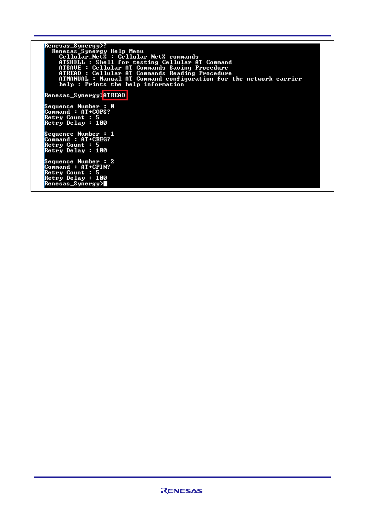
Renesas Synergy™ Platform Cellular Framework
Figure 51. Output of ATREAD command
8. To execute the AT commands saved in the internal flash, execute the ‘run_config’ command under the
ATMANUAL menu as shown in the following figure. The CLI needs APN, Context ID and PDP from the
user for the network carrier. After provisioning the module using ‘run_config’ command, the user can
test the data connection using ‘ping’ command as shown in the following figure.
Note: Power cycle the boar d if needing to execute ‘run_config’ command after the ‘ping’ command again.
R30AN0311EU0105 Rev.1.05 Page 65 of 70
Apr.26.19
Page 66

Renesas Synergy™ Platform Cellular Framework
Figure 52. Output for ATMANUAL Command
8.4 Install the USB CDC Device Driver
The console framework in this application project uses the communication framework on USB CDC Device.
This requires the USB CDC device driver being installed on the PC.
For Windows10 PC, it is not necessary to install the USB CDC device driver as the PK-S5D9 can be
detected as a USB serial device as shown in the figure that follows.
R30AN0311EU0105 Rev.1.05 Page 66 of 70
Apr.26.19
Page 67

Renesas Synergy™ Platform Cellular Framework
Figure 53. USB CDC Port Enumeration on Windows10
For Windows 7, after the SK-S7G2 USB device port is connected to the PC, it is first detected as Unknown
Device. You can then right-click on this device and select Update Driver software.
When prompted for the location of the drivers, browse to the location of the Windows USB serial driver
provided as part of this application project. After the driver is updated, a new COM device is displayed in the
Device Manager as in Windows 10.
9. Cellular Framework Module Conclusion
This Application note has provided all the background information needed to select, add, configure, and use
the Cellular Framework module in an example project. Many of these steps were time consuming and errorprone activities in previous generations of embedded systems. The Renesas Synergy
these steps much less time consuming and removes the common errors, like conflicting configuration
settings or incorrect selection of lower-level drivers. The use of high-level APIs as demonstrated in this
Application Note illustrates additional development time savings, by allowing work to begin at a high level,
and avoiding the time required in previous generation embedded of development environments to use or, in
some cases, create lower-level drivers.
™
Platform makes
10. Cellular Framework Module Next Steps
After you have mastered a simple Cellular Framework project, you may want to review a more complex
example. Visit the Renesas Synergy™ Solutions Gallery at www.renesas.com/synergy/solutionsgallery for
other Cellular-based applications.
R30AN0311EU0105 Rev.1.05 Page 67 of 70
Apr.26.19
Page 68

Renesas Synergy™ Platform Cellular Framework
11. Reference Information
SSP User’s Manual: Available in html format in the SSP distribution package and as a pdf format from the
Renesas Synergy Gallery. To find the most up-to-date reference materials and their locations, visit the
Synergy Knowledge Base and enter a search for the module name + Module Guide Resources.
For example, if you are looking for sf_cellular, enter sf_cellular + Module Guide Resources in the search
field or simply visit https://en-support.renesas.com/knowledgeBase/16977531.
• A reader who wishes to use this guide as a hands-on method for implementing the application example
2
(as opposed to just a learning reference) needs to have an ISDE (e
®
Workbench
for Renesas Synergy™ with the appropriate version of SSP) installed and running on a
studio ISDE or IAR Embedded
computer. The SSP User’s Manual for the Renesas Synergy Platform can be helpful.
• In addition to the ISDE and SSP, a hardware target is needed to see the example project running on a
Synergy MCU. For this prerequisite, a kit can be purchased from any Renesas authorized distributor and
you can find a kit on a distributor’s website by simply searching for the kit name in the distributor’s search
window. The kit targeted by this application example project is PK-S5D9
In addition to the Synergy MCU kit, for the North American market Verizon service provider, the user needs
to purchase the NimbeLink PMOD adaptor, Cellular Hardware Module, and SIM card that is supported for
the module. These can be purchased from the following links:
https://www.digikey.com/product-detail/en/NL-SW-LTE-TSVG/1477-1011-ND/4977073
https://www.digikey.com/product-detail/en/nimbelink-llc/NL-AB-PMOD-SYN/1477-1038-ND/5825469
https://www.digikey.com/products/en?keywords=ANT%20EXT%20GPS%2FLTE%20SMAM%20HINGED%2
072MM
https://www.digikey.com/products/en?keywords=SIM%204G%20VERIZON%203FF
For CATM1 Modules Visit https://www.rakwireless.com/en/beta or Contact the Renesas Sales
Representative.
Note: You can also visit the http://nimbelink.com/ for more details on the supported Modems for different
regions.
This guide assumes the reader is familiar with using a Synergy ISDE and the SSP for creating projects,
adding threads, creating stacks, configuring modules, running, and debugging. Reading the Getting Start ed
2
Guides, (for e
studio ISDE, IAR Embedded Workbench® for Renesas Synergy™, and SSP) viewing
introductory videos, and taking tutorial labs can all be used for this prerequisite.
Synergy Knowledge Base:
www.renesas.com/synergy/knowledgebase
BG96 modem Cellular Connectivity Knowledge Base:
https://en.na4.teamsupport.com/knowledgeBase/18027787
R30AN0311EU0105 Rev.1.05 Page 68 of 70
Apr.26.19
Page 69

Renesas Synergy™ Platform Cellular Framework
Website and Support
Visit the following vanity URLs to learn about key elements of the Synergy Platform, download components
and related documentation, and get support.
Synergy Software www.renesas.com/synergy/software
Synergy Software Package www.renesas.com/synergy/ssp
Software add-ons www.renesas.com/synergy/addons
Software glossary www.renesas.com/synergy/softwareglossary
Development tools www.renesas.com/synergy/tools
Synergy Hardware www.renesas.com/synergy/hardware
Microcontrollers www.renesas.com/synergy/mcus
MCU glossary www.renesas.com/synergy/mcuglossary
Parametric search www.renesas.com/synergy/parametric
Kits www.renesas.com/synergy/kits
Synergy Solutions Gallery www.renesas.com/synergy/solutionsgallery
Partner projects www.renesas.com/synergy/partnerprojects
Application projects www.renesas.com/synergy/applicationprojects
Self-service support resources:
Documentation www.renesas.com/synergy/docs
Knowledgebase www.renesas.com/synergy/knowledgebase
Forums www.renesas.com/synergy/forum
Training www.renesas.com/synergy/training
Videos www.renesas.com/synergy/videos
Chat and web ticket www.renesas.com/synergy/resourcelibrary
R30AN0311EU0105 Rev.1.05 Page 69 of 70
Apr.26.19
Page 70

Renesas Synergy™ Platform Cellular Framework
Rev.
Date
Description
Page
Summary
1.00
Aug.30.17
—
Initial release
1.01
Oct.11.17
—
Added Support for CAT1 and SSP v1.3.2
1.02
Oct.26.17
—
Updated for SSP v1.3.2
1.03
Mar.23.18
—
Updated for SSP v1.4.0
1.04
Oct.09.18
—
Updated for SSP v1.5.0
1.05
Apr.26.19
—
Updated for SSP v1.6.0
Revision History
R30AN0311EU0105 Rev.1.05 Page 70 of 70
Apr.26.19
Page 71

Corporate Headquarters
Contact information
www.renesas.com
Trademarks
of their respective owners.
Notice
1. Descriptions of circuits, software and other related information in this document are provided only to illustrate the operation of semiconductor products
and application examples. You are fully responsible for the incorporation or any other use of the circuits, software, and information in the design of your
product or system. Renesas Electronics disclaims any and all liability for any losses and damages incurred by you or third parties arising from the use
of these circuits, software, or information.
2. Renesas Electronics hereby expressly disclaims any warranties against and liability for infringement or any other claims involving patents, copyrights,
or other intellectual pro pe rt y rig hts of th i rd par ties, by or arising from the use of Renesas Electronics products or technical information described in this
document, including but not limited to, the product data, drawings, charts, programs, algorithms, and application examples.
3. No license, express, implied or otherwise, is granted hereby under any patents, copyrights or other intellectual property rights of Renesas Electronics
or others.
4. You shall not alter, modify, copy, or reverse engineer any Renesas Electronics product, whether in whole or in part. Renesas Electronics disclaims any
and all liability for any losses or damages incurred by you or third parties arising from such alteration, modification, copying or reverse engineering.
5. Renesas Electronics products are classified according to the following two quality grades: “Standard” and “High Quality”. The intended applications for
each Renesas Electronics product depends on the product’s quality grade, as indicated below.
"Standard": Computers; office equipment; communications equipment; test and measurement equipment; audio and visu al equipment; home
"High Quality": Transportation equipment (automobiles, trains, ships, etc.); traffic control (traffic lights); large-scale communication equipment; key
Unless expressly designated as a high reliability product or a product for harsh environments in a Renesas Electronics data sheet or other Renesas
Electronics document, Renesas Electronics products are not intended or authorized for use in products or systems that may pose a direct threat to
human life or bodily injury (artificial life support devices or systems; surgical implantations; etc.), or may cause serious property damage (space
system; undersea repeaters; nuclear power control systems; aircraft control systems; key plant systems; military equipment; etc.). Renesas Electronics
disclaims any and all liability for any damages or losses incurred by you or any third parties arising from the use of any Renesas Electronics product
that is inconsistent with any Renesas Electronics data sheet, user’s manual or other Renesas Electronics document.
6. When using Renesas Electronics products, refer to the latest product information (data sheets, user’s manuals, application notes, “General Notes for
Handling and Using Semiconductor Devices” in the reliability handbook, etc.), and ensure that usage conditions are within the ranges specified by
Renesas Electronics with respect to maximum ratings, operating power supply voltage range, heat dissipation characteristics, installation, etc. Renesas
Electronics disclaims any and all liability for any malfunctions, failure or accident arising out of the use of Renesas Electronics produ cts out si de of s uc h
specified ranges.
7. Although Renesas Electronics endeavors to improve the quality and reliability of Renesas Electronics products, semiconductor products have specific
characteristics, such as the occurrence of failure at a certain rate and malfunctions under certain use conditions. Unless designated as a high reliability
product or a product for harsh environments in a Renesas Electronics data sheet or other Renesas Electronics document, Renesas Electronics
products are not subject to radiation resistance design. You are responsible for implementing safety measures to guard against the possibility of bodily
injury, injury or damage caused by fire, and/or danger to the public in the event of a failure or malfunction of Renesas Electronics products, such as
safety design for hardware and software, including but not limited to redundancy, fire control and malfunction prevention, appropriate treatment for
aging degradation or any other appropriate measures. Because the evaluation of microcomputer software alone is very difficult and impractical, you are
responsible for evaluating the safety of the final products or systems manufactured by you.
8. Please contact a Renesas Electronics sales office for details as to environmental matters such as the environmental compatibility of each Renesas
Electronics product. You are responsible for carefully and sufficiently investigating applicable laws and regulations that regulate the inclusion or use of
controlled substances, including without limitation, the EU RoHS Directive, and using Renesas Electronics products in compliance with all these
applicable laws and regulations. Renesas Electronics disclaims any and all liability for damages or losses occurring as a result of your nonc om pliance
with applicable laws and regulations.
9. Renesas Electronics products and technologies shall not be used for or incorporated into any products or systems whose manufacture, use, or sale is
prohibited under any applicable domestic or foreign laws or regulations. You shall comply with any applicable export control laws and regulations
promulgated and administered by the governments of any countries asserting jurisdiction over the parties or transactions.
10. It is the responsibility of the buyer or distributor of Renesas Electronics products, or any other party who distributes, disposes of, or otherwise sells or
transfers the product to a third party, to notify such third party in advance of the contents and conditions set forth in this document.
11. This document shall not be reprinted, reproduced or duplicated in any form, in whole or in part, without prior written consent of Renesas Electronics.
12. Please contact a Renesas Electronics sales office if you have any questions regarding the information contained in this document or Renesas
Electronics products.
(Note1) “Renesas Electronics” as used in this document means Renesas Electronics Corporation and also includes its directly or indirectly controlled
(Note2) “Renesas Electronics product(s)” means any product developed or manufactured by or for Renesas Electronics.
subsidiaries.
electronic appliances; machine tools; personal electronic equipment; industrial robots; etc.
financial terminal systems; safety control equipment; etc.
(Rev.4.0-1 Novembe r 201 7)
TOYOSU FORESIA, 3-2-24 Toyosu,
Koto-ku, Tokyo 135-0061, Japan
Renesas and the Renesas logo are trademarks of Renesas Electronics
Corporation. All trademarks and registered trademarks are the property
For further information on a product, technology, the most up-to-date
version of a document, or your ne are s t sales office, please visit:
www.renesas.com/contact/.
© 2019 Renesas Electronics Corporation. All rights reserved.
 Loading...