

Page 1

Application Note
Renesas Synergy™ Platform
Audio Record ADC Framework Module Guide
Introduction
This module guide will enable you to effectively use a module in your own design. Upon completion of this
guide you will be able to add this module to your own design, configure it correctly for the target application,
and write code using the included application project code as a reference and efficient starting point.
References to more detailed API descriptions and suggestions of other application projects that illustrate
more advanced uses of the module are available in the Renesas Synergy Knowledge Base (as described in
the References section in this document) and should be valuable resources for creating more complex
designs.
The Audio Record ADC Framework module is a high-level API for audio recording applications and is
implemented on sf_adc_periodic. The Audio Record ADC Framework module uses the ADC, GPT, and
DTC peripherals on the Synergy MCU. A user-defined callback can be created to indicate that the sample
count has been completed.
Contents
1. Audio Record ADC Framework Module Features .................................................................... 2
2. Audio Record ADC Framework Module APIs Overview ........................................................... 2
3. Audio Record ADC Framework Module Operational Overview ................................................ 3
3.1 Audio Record ADC Framework Module Operational Notes .................................................................... 3
3.2 Audio Record ADC Framework Module Limitations ................................................................................ 3
4. Including the Audio Record ADC Framework Module in an Application ................................... 4
5. Configuring the Audio Record ADC Framework Module .......................................................... 4
5.1 Configuration Settings for the Audio Record ADC Framework Module Low Level Drivers .................... 5
5.2 Audio Record ADC Framework Module Clock Configuration.................................................................. 9
5.3 Audio Record ADC Framework Module Pin Configuration ..................................................................... 9
6. Using the Audio Record ADC Framework Module in an Application ...................................... 10
7. Audio Record ADC Framework Module Application Project ................................................... 11
8. Customizing the Audio Record ADC Framework Module for a Target Application ................. 14
9. Running the Audio Record ADC Framework Module Application Project ............................... 14
10. Audio Record ADC Framework Module Conclusion ............................................................... 16
11. Audio Record ADC Module Next Steps .................................................................................. 16
12. Audio Record ADC Module Reference Information ................................................................ 16
Revision History ............................................................................................................................ 18
R30AN0312EU0120 Rev.1.20 Page 1 of 18
Apr.29.19
Page 2
Renesas Synergy™ Platform Audio Record ADC Framework Module Guide
Function Name
Example API Call and Description
.open
g_sf_audio_record_adc.p_api->open(g_sf_audio_record_adc.p_ctrl,
Initialize the module.
.start
g_sf_audio_record_adc.p_api-
Start audio recording.
.stop
g_sf_audio_record_adc.p_api->stop(g_sf_audio_record_adc.p_ctrl);
Stop audio recording.
.infoGet
g_sf_audio_record_adc.p_api-
Get the channel information (mono or Stereo).
.close
g_sf_audio_record_adc.p_api-
Close the module.
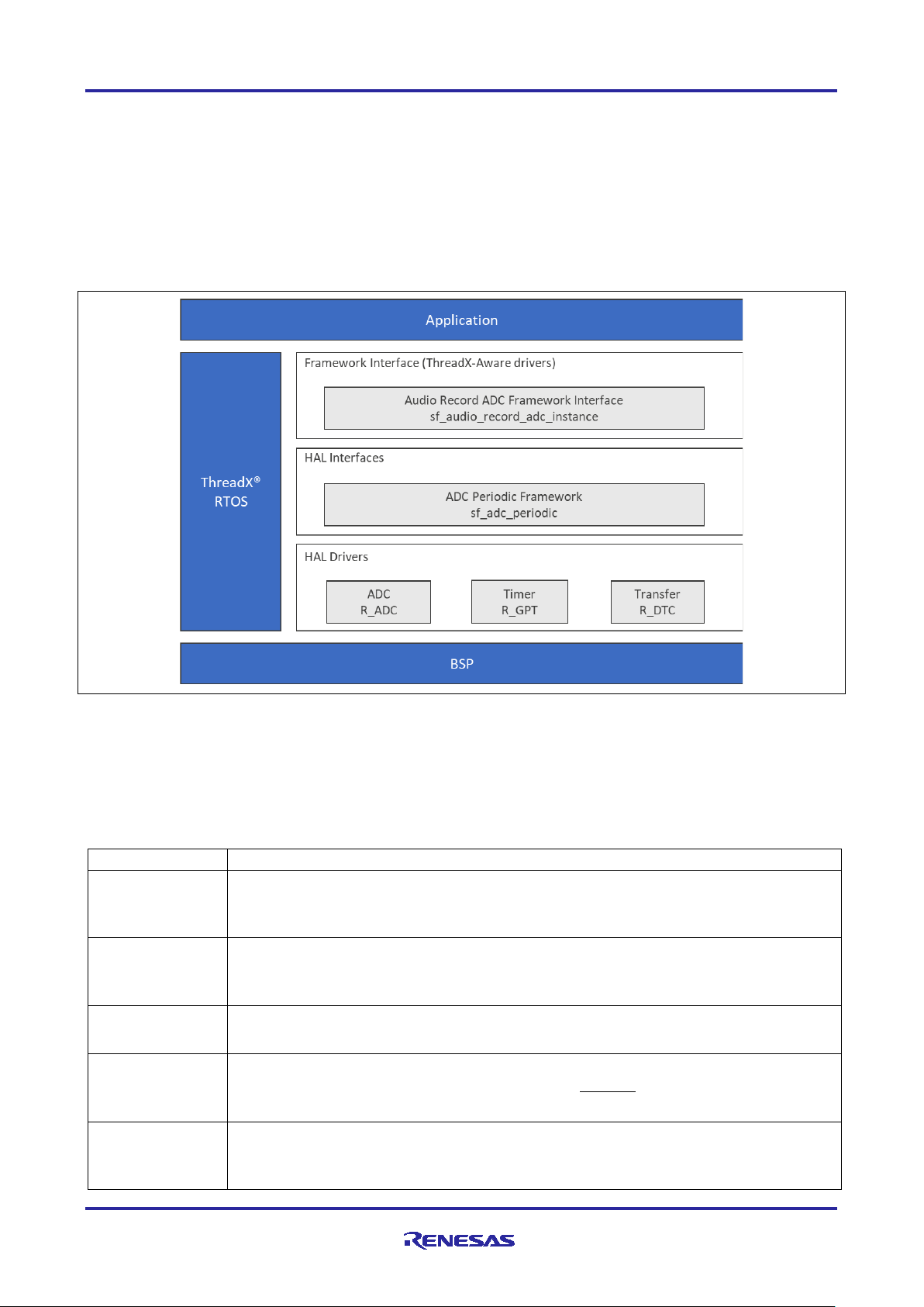
1. Audio Record ADC Framework Module Features
• Records data in 8-bit or 12-bit PCM
• Uses ADC Periodic Framework to simplify configuration and integration
• Uses ThreadX
• APIs for high-level functions simplify coding:
Open, start
Stop, infoGet
Close
®
object, like mutex, to protect hardware from improper access
Figure 1. Audio Record ADC Framework Module Organiza tion, Options and Stack Implementations
2. Audio Record ADC Framework Module APIs Overview
The Audio Record ADC Framework module defines APIs for opening, closing, starting, and stopping the
record process. A complete list of the available APIs, an example API call, and a short description of each
can be found in the following table. A table of status return values follows.
Table 1
. Audio Record ADC Framework Module API Summary
g_sf_audio_record_adc.p_cfg);
>start(g_sf_audio_record_adc.p_ctrl);
>infoGet(g_sf_audio_record_adc.p_api.p_ctrl);
>close(g_sf_audio_record_adc.p_ctrl);
R30AN0312EU0120 Rev.1.20 Page 2 of 18
Apr.29.19
Page 3
Renesas Synergy™ Platform Audio Record ADC Framework Module Guide
.versionGet
g_sf_audio_record_adc.p_api->versionGet(&version);
Name
Description
SSP_SUCCESS
API Call Successful
SSP_ERR_INVALID_ARGUMENT
Parameter has invalid value
SSP_ERR_IN_USE
The adc periodic framework mutex may be unavailable for the unit
requested. See HAL driver for other possible causes.
SSP_ERR_INTERNAL
An internal ThreadX error has occurred. This is typically a failure to
SSP_ERR_NOT_OPEN
Unit is not open
SSP_ERR_ASSERTION
The parameter p_ctrl or p_sample is NULL
SSP_ERR_UNSUPPORTED
This function is not supported by the HAL driver
(p_ctrl > p_api > close is NULL)
Retrieve the API version with the version point er .
Note: For more complete descriptions of operation and definitions for the function data structures, typedefs,
defines, API data, API structures, and function variables, review the SSP User’s Manuals API
References for the associated module.
Table 2. Status Return Values
create/use a mutex or to create an internal thread.
Note: Lower level drivers may return Common Error Codes. Refer to the SSP User’s Manual API
References for the associated module for a definition of all relevant status return values.
3. Audio Record ADC Framework Module Operational Overview
The Audio Record ADC Framework Module samples audio analog data using the ADC Periodic Framework
and the data samples captured are stored in the user buffer. The data is made available for further
processing as needed by the application. The Audio Record ADC Framework Module has a configuration
parameter that is initialized during the framework initialization, which also initializes the underlying ADC
periodic framework for data capture.
The data is captured in a user defined buffer and this is done in the callback function as illustrated as follows,
assuming that the name of the callback has been configured to be sf_audio_record_user_callback:
uint16_t * audio_record_buffer;
void sf_audio_record_user_callback (sf_audio_record_callback_args_t *p_args)
{
audio_record_buffer = ((uint16_t *)g_sf_audio_record_adc.p_cfg->
p_capture_data_buffer + (p_args->buffer_index/2));
3.1 Audio Record ADC Framework Module Operational Notes
The Audio Record ADC Framework Module configuration data can specify the length of the data buffer, data
width, sampling rate, and the number of sampling iterations.
3.2 Audio Record ADC Framework Module Limitations
• Currently the Audio Record ADC only supports the ADC Periodic Framework as the lower level and thus
recording via I2S is not supported with the framework.
• The framework currently supports recording 8-bit or 12-bit PCM data.
• Refer to the most recent SSP Release Note for any additional operational limitations for this module.
R30AN0312EU0120 Rev.1.20 Page 3 of 18
Apr.29.19
Page 4
Renesas Synergy™ Platform Audio Record ADC Framework Module Guide
Resource
ISDE Tab
Stacks Selection Sequence
g_audio_record_adc0 Au di o
sf_audio_record_adc
Threads
New Stack> Framework> Audio> Audio
sf_audio_record_adc
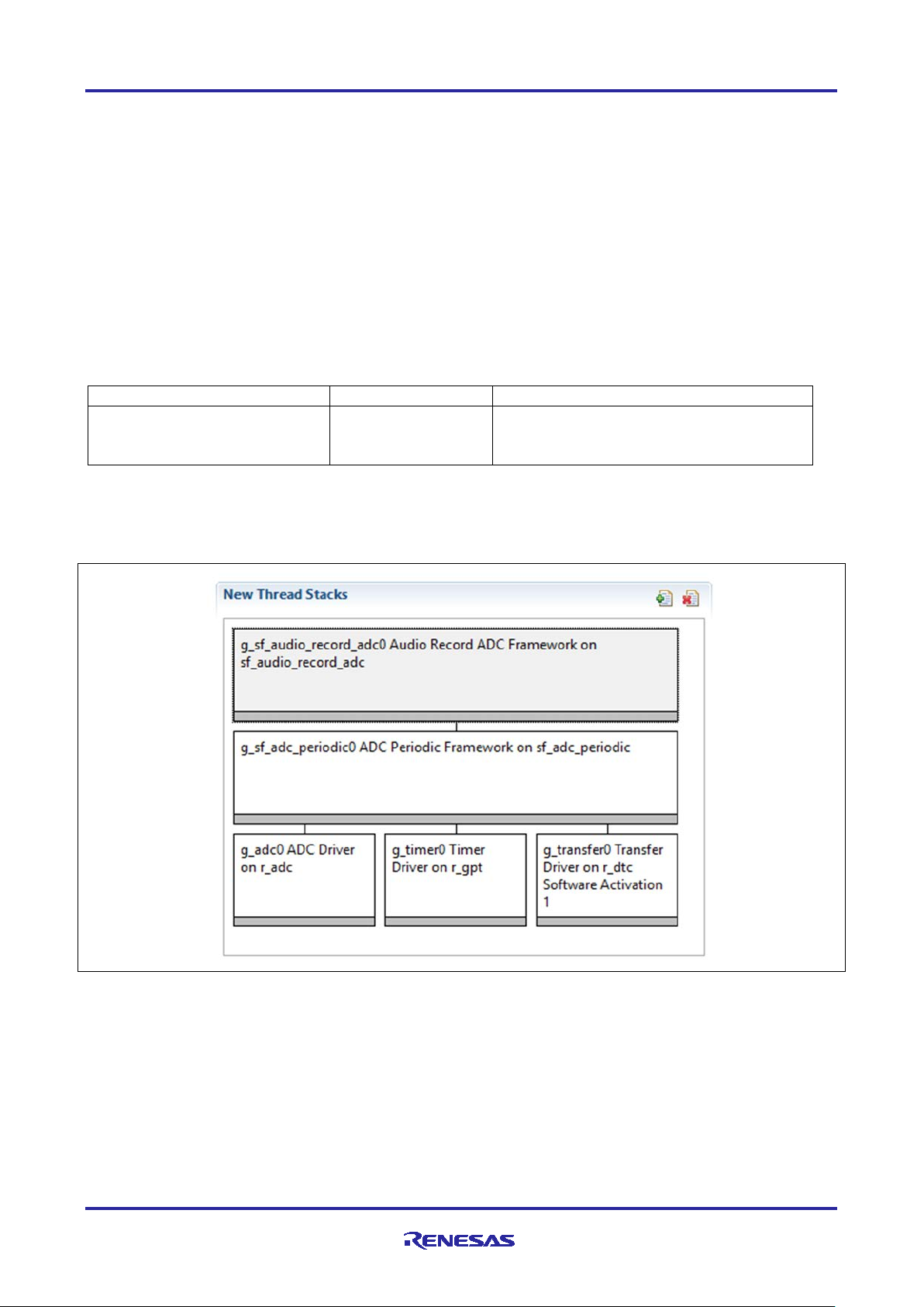
4. Including the Audio Record ADC Framework Module in an Application
This section describes how to include the Audio Record ADC Framework Module in an application using the
SSP Configurator.
Note: This section assumes that you are familiar with creating a project, adding threads, adding a stack to a
thread, and configuring a block within the stack. If you are unfamiliar with any of these items, refer to
the first few chapters of the SSP User’s Manual to learn how to manage each of these important steps
in creating SSP based applications.
To add the Audio Record ADC Framework Module to an application, simply add it to a thread using the
Stacks Selection Sequence given in the following table. (The default name for the Audio Record ADC
Framework Module is g_audio_record_adc0.) This name can be changed in the associated Properties
window.
Table 3. Audio Record ADC Framework Module Selection Sequence
Record ADC Framework on
When the Audio Record ADC on sf_audio_record_adc is added to the Thread Stack as shown in the
following figure, the configurator automatically adds any needed lower level drivers.
Record ADC Framework on
Figure 2. Audio Record ADC Framework Module Stack
5. Configuring the Audio Record ADC Framework Module
The Audio Record ADC Framework Module must be configured by you for the desired operation. The SSP
configuration window will automatically identify, by highlighting the block in red, any required configuration
selections, such as Interrupts or Operating modes, which must be configured for lower level modules, for
successful operation. Only those properties that can be changed without causing conflicts are available for
modification. Other properties are locked and not available for changes and are identified with a lock icon
for the locked property in the Property window in the ISDE. This approach simplifies the configuration
process and makes it much less error prone than previous manual approaches to configuration. The
R30AN0312EU0120 Rev.1.20 Page 4 of 18
Apr.29.19
Page 5
Renesas Synergy™ Platform Audio Record ADC Framework Module Guide
ISDE Property
Value
Description
Parameter Checking
Enabled, Disabled, BSP
Default: BSP
Selects if code for parameter checking is to
Name
g_sf_audio_record_adc0
Module name
Name of the data-buffer to
P_capture_data_buffer
Name of the data buffer to store samples
Length of the data-buffer
2048
Length of the buffer to which data is to be
stored
Audio Record Data Size
8-bit, 16-bit
Data width
Sampling Rate in HZ
8000
Sampling rate
Number of sampling
Default: 256
Number of samples captured per iteration
Callback
g_audio_redord_framework_
User function that will be called once the
been buffered.
ISDE Property
Value
Description
Parameter Checking
Enabled, Disabled, BSP
Default: BSP
Selects if code for parameter checking is to
Name
g_sf_adc_periodic0
Module name
available configuration settings and defaults for all the user accessible properties are given in the properties
tab within the SSP Configurator, and are shown in the following tables for easy reference.
One of the properties most often identified as requiring a change is the Interrupt Priority. This configuration
setting is available with the Properties window of the associated module. Simply select the indicated module
and then view the properties window. The Interrupt settings are often toward the bottom of the properties list,
so scroll down until they become available. Also note that the Interrupt Priorities listed in the properties
window in the ISDE will include an indication as to the validity of the setting based on the MCU targeted
(CM4 or CM0+). This level of detail is not included in the following configuration properties tables, but is
easily visible with the ISDE when configur i ng Interr up t Pr iori t y levels.
Note: You may want to open your ISDE and create the module and explore the property settings in parallel
with looking over the following Configuration Table Settings. This will help orient you and can be a
useful hand-on approach to learning the ins and outs of developing with SSP.
Table 4. Configuration Settings for Audio Record ADC Framework Module on sf_audio_record_adc
be included in the build
store samples
Default: 8-bit
iterations
user_callback
Note: The above setting examples and defaults are for a project using the S7G2 Synergy MCU Group.
Other MCUs may have different default values and available configuration settings.
In some cases, settings other than the defaults for stack modules can be desirable. For example, it might be
useful to select different buffer sizes or sample rates. The configurable properties for the lower level stack
modules are given in the following sections for completeness and as a reference.
Note: Most of the property settings for modules are fairly intuitive and usually can be determined by
inspection of the associated properties window from the SSP Configurator.
number of sampling iterations of data has
5.1 Configuration Settings for the Audio Record ADC Framework Module Low
Level Drivers
Typically, only a small number of settings must be modified from the default for lower level drivers and these
are indicated with red text in the Thread Stack block. Notice that some of the configuration properties must
be set to a certain value for proper framework operation and will be locked to prevent user modification. The
following tables identify all the settings within the properties section for the module.
Table 5. Configuration Settings for ADC Periodic Framework on sf_adc_periodic
R30AN0312EU0120 Rev.1.20 Page 5 of 18
Apr.29.19
be included in the build
Page 6
Renesas Synergy™ Platform Audio Record ADC Framework Module Guide
ISDE Property
Value
Description
Name of the data-buffer
to store samples
g_user_buffer
Name of the data buffer to store samples
Length of the data-buffer
2048
Length of the buffer to which data is to be
Number of sampling
iterations
256
Number of samples captured per iteration
GPT Timer channel used
Channel 0-12
Channel number
Callback
NULL
User function that will be called once the
been buffered
ISDE Property
Value
Description
Parameter Checking
BSP, Enabled, Disabled
If selected code for parameter checking is
Name
g_adc0
Module name
Unit
0, 1 (S7G2 Only)
Default: 0
Specify the ADC Unit to be used. The S7G2
Resolution
14-Bit (S3A7/S124 Only),
Default: 8-Bit (S7G2 Only)
Specify the conversion resolution for this unit.
Alignment
Right, Left
Specify the conversion result alignment.
Clear after read
Off, On
Specify if the result register must be
results in a 0.
Mode
Single Scan
The ADC Framework preconfigures and locks
this field.
Channels 0-6
Unused, Use in
In Normal mode of operation, this bitmask
specify which channels belong to group A.
Channels 7-10
Unused, Use in
In Normal mode of operation, this bitmask
specify which channels belong to group A.
Channels 11-15
Unused, Use in
In Normal mode of operation, this bitmask
specify which channels belong to group A.
stored
to trigger scan
number of sampling iterations of data has
Table 6. Configuration Settings for the ADC HAL Module on r_adc
Default: Enabled
12-Bit, 10-Bit (S7G2 Only),
8-Bit (S7G2 Only)
Default: Right
Default: On
Normal/Group A, Use in
Group B
Default: Unused
included in the build
has two units; 0 and 1.
automatically cleared after the conversion
result is read.
Note: If this is enabled, then watching the
result register using a debugger always
field is used to specify the channels that are
enabled in that ADC unit. For example, if it is
set to 0x101, then channels 0 and 2 are
enabled. In group mode, this field is used to
(S3A7/S124 Only)
(S3A7 Only)
R30AN0312EU0120 Rev.1.20 Page 6 of 18
Apr.29.19
Normal/Group A, Use in
Group B
Default: Unused
Normal/Group A, Use in
Group B
Default: Unused
field is used to specify the channels that are
enabled in that ADC unit. For example, if it is
set to 0x101, then channels 0 and 2 are
enabled. In group mode, this field is used to
field is used to specify the channels that are
enabled in that ADC unit. For example, if it is
set to 0x101, then channels 0 and 2 are
enabled. In group mode, this field is used to
Page 7

Renesas Synergy™ Platform Audio Record ADC Framework Module Guide
ISDE Property
Value
Description
Channels 16-20
Unused, Use in
In Normal mode of operation, this bitmask
specify which channels belong to group A.
Channel 21
Unused, Use in
In Normal mode of operation, this bitmask
Channel 22 (S3A7/S124
Unused, Use in
In Normal mode of operation, this bitmask
specify which channels belong to group A.
Channels 23-27
Unused, Use in
In Normal mode of operation, this bitmask
Temperature Sensor
Unused, Use in
Default: Unused
Temperature sensor use selection for
Voltage Sensor
Unused, Use in
Voltage sensor use selection for Channel
Scan Mask Group B
Use #define
channels.
Do not use with ADC Framework since the
Normal/Group A Trigger
ELC Event
The ADC Framework preconfigures and locks
Group B Trigger
Scan Mode)
ELC Event (The only valid
The ADC Framework preconfigures and locks
Group Priority
Group A cannot interrupt
Do not use with ADC Framework since the
(Unit 0 Only)
Only)
(S3A7 Only)
Normal/Group A, Use in
Group B
Default: Unused
Normal/Group A, Use in
Group B
Default: Unused
Normal/Group A, Use in
Group B
Default: Unused
Normal/Group A, Use in
Group B
Default: Unused
field is used to specify the channels that are
enabled in that ADC unit. For example, if it is
set to 0x101, then channels 0 and 2 are
enabled. In group mode, this field is used to
field is used to specify the channels that are
enabled in that ADC unit. For example, if it is
set to 0x101, then channels 0 and 2 are
enabled. In group mode, this field is used to
specify which channels belong to group A.
field is used to specify the channels that are
enabled in that ADC unit. For example, if it is
set to 0x101, then channels 0 and 2 are
enabled. In group mode, this field is used to
field is used to specify the channels that are
enabled in that ADC unit. For example, if it is
set to 0x101, then channels 0 and 2 are
enabled. In group mode, this field is used to
specify which channels belong to group A.
(Valid Only in Group
(Valid only in Group Scan
Mode)
Normal/Group A, Use in
Group B
Normal/Group A, Use in
Group B
Default: Unused
ADC_MASK_xxx which are
defined in r_adc.h. Use
(ADC_MASK_xxx|ADC_MA
SK_xxx ) for multiple
trigger for either group in
Group Scan Mode)
Group B, Group A can
interrupt Group B; Group B
scan restarts at next trigger,
Group A can interrupt Group
B; Group B scan restarts
immediately, Group A can
interrupt Group B; Group B
scan restarts immediately
and scans continuously
Default: Group A cannot
interrupt Group B
Channel Scan Mask
Scan Mask
mode is locked to Single Scan Mode.
this field.
this field.
mode is locked to Single Scan Mode.
R30AN0312EU0120 Rev.1.20 Page 7 of 18
Apr.29.19
Page 8

Renesas Synergy™ Platform Audio Record ADC Framework Module Guide
ISDE Property
Value
Description
Add/Average Count
Disabled, Add two samples,
Default: Disabled
Specify if addition or averaging needs to be
Channels 0-27
Disabled, Enabled
This field is valid only if
to be averaged or summed.
Temperature Sensor
Disabled, Enabled
Default: Disabled
Temperature sensor use selection for
Voltage Sensor
Disabled, Enabled
Voltage sensor use selection for
Channels 0-2
Disabled, Enabled
Determines which of channels 0, 1, and 2 are
channels 0, 1, and 2.
Sample Hold States
24
If selected code for parameter checking is
Callback
NULL
Module name
Scan End Interrupt
Priority 0 (highest), Priority
Specify the ADC Unit to be used. The S7G2
Scan End Group B
Priority 0 (highest), Priority
Default: Disabled
Specify the conversion resolution for this unit.
ISDE Property
Value
Description
Parameter Checking
BSP, Enabled, Disabled
Enables or disables the parameter checking.
Name
g_timer0
Module name.
Channel
0
The ADC Framework preconfigures and locks
(Applies only to the 3
channels selected above)
Add three samples, Add four
samples, Add sixteen
samples, Average two
samples, Average four
samples
Default: Disabled
Default: Disabled
Default: Disabled
done for any of the channels in this unit. The
actual channels are specified by using a
channel mask adc_channel_cfg_t::add_mask.
adc_cfg_t::add_average_count is enabled.
This field determines what channel results are
Addition/Averaging Mask
Addition/Averaging Mask
using the updated sample-and-hold states
value specified in
adc_channel_cfg_t::sample_hold_states. This
field must only be set if it is desired to modify
the default sample and hold count value for
included in the build
Priority
Interrupt Priority
Table 7. Configuration for the GPT HAL Module on r_gpt
1:2, Priority 3 (CM4: valid,
CM0+: lowest- not valid if
using ThreadX), Priority 4:14
(CM4: valid, CM0+: invalid),
Priority 15 (CM4 lowest - not
valid if using ThreadX,
CM0+: invalid)
Default: Disabled
1:2, Priority 3 (CM4: valid,
CM0+: lowest- not valid if
using ThreadX), Priority 4:14
(CM4: valid, CM0+: invalid),
Priority 15 (CM4 lowest - not
valid if using ThreadX,
CM0+: invalid)
Default: BSP
has two units; 0 and 1.
R30AN0312EU0120 Rev.1.20 Page 8 of 18
Apr.29.19
this field based on channel selected in the
ADC Framework.
Page 9

Renesas Synergy™ Platform Audio Record ADC Framework Module Guide
ISDE Property
Value
Description
Mode
Periodic
The ADC Framework preconfigures and locks
this field.
Period Value
10
Configure timer period to trigger ADC scans.
Period Unit
Raw Counts, Nanoseconds,
Default: Milliseconds
Configure units of the timer period set above.
Duty Cycle Value
50
Duty cycle value selection
Duty Cycle Unit
Unit Raw Counts, Unit
Default: Unit Raw Counts
Duty cycle unit selection
Auto Start
False
The ADC Framework preconfigures and locks
GTIOCA Output Enabled
True, False
Set to true to output the timer signal on a port
output of the timer signal.
GTIOCA Stop Level
Pin Level Low, Pin Level
Controls output pin level when the timer is
GTIOCB Output Enabled
True, False
Set to true to output the timer signal on a port
output of the timer signal.
GTIOCB Stop Level
Pin Level Low, Pin Level
Controls output pin level when the timer is
Callback
NULL
The ADC Framework preconfigures and locks
this field.
Interrupt Priority
Priority 0 (highest), Priority
Interrupt priority selection
Microseconds, Millisecon ds ,
Seconds, Hertz, Kilohertz
Percent, Unit Percent x 1000
this field.
Default: False
High, Pin Level Retained
Default: Pin Level Low
Default: False
High, Pin Level Retained
Default: Pin Level Low
1:2, Priority 3 (CM4: valid,
CM0+: lowest- not valid if
using ThreadX), Priority 4:14
(CM4: valid, CM0+: invalid),
Priority 15 (CM4 lowest - not
valid if using ThreadX,
CM0+: invalid)
Default: Disabled
Note: The above setting examples and defaults are for a project using the S7G2 Synergy MCU Group.
Other MCUs may have different default values and available configuration settings.
pin configured for GPT. Set to false for no
stopped.
pin configured for GPT. Set to false for no
stopped.
5.2 Audio Record ADC Framework Module Clock Configuration
The ADC peripheral module uses PCLKC as its clock source.
5.3 Audio Record ADC Framework Module Pin Configuration
The ADC peripheral module uses pins on the MCU to communicate to external devices. I/O pins must be
selected and configured as required by the external device. ADC pins must be configured as analog pins.
The first table that follows illustrates the method for selecting the pins within the SSP configuration window
and the next table illustrates an example selection for the pins.
Note: For some peripherals, the Operation Mode selection mode determines what peripheral signals are
available and therefore what MCU pins are required.
R30AN0312EU0120 Rev.1.20 Page 9 of 18
Apr.29.19
Page 10

Renesas Synergy™ Platform Audio Record ADC Framework Module Guide
Resource
ISDE Tab
Pin selection Sequence
ADC
Pins
Select Peripherals > Analog:ADC > ADC0
Pin Configuration
Property
Value
Description
Operation Mode
Disabled, Custom
Default: Custom
Select operating mode for ADC
ADTRG
None, P407, P102
Default: None
ADTRG Pin
AN00-19
None, Pnnn, Pmmm
Analog input pins
PGAVSS0
None, P003
Default: None
PGAVSS pin
Table 8. Pin Selection Sequence for ADC
Note: The above selection sequence assumes ADC0 is the desired hardware target for the driver.
Table 9. Pin Configuration Settings for ADC
Default: None
Note: The preceding example settings are for a project using the S7G2 Synergy MCU Group and the SK-
S7G2 Kit. Other Synergy Kits and other Synergy MC U s ma y have differ ent availa ble pin configuration
settings.
6. Using the Audio Record ADC Framework Module in an Application
The typical steps in using the Audio Record ADC Framework module in an application are:
1. Open the module using the open API.
2. Start the recording using the start API.
3. Buffer data in a user buffer with the callback.
4. Operate on data as needed.
5. Close the module using the close API.
The above common steps are illustrated in a typical operational flow diagram in the following figure.
Figure 3. Flow Diagram of a Typical Audio Record A DC Framework Module Application
R30AN0312EU0120 Rev.1.20 Page 10 of 18
Apr.29.19
Page 11

Renesas Synergy™ Platform Audio Record ADC Framework Module Guide
e2 studio ISDE
v7.3.0 or greater
Integrated Solution Development Environment
SSP
v1.6.0 or greater
Synergy Software Platform
IAR EW for Renesas Synergy
v8.23.3 or greater
IAR Embedded Workbench for Renesas Synergy
SSC
v7.3.0 or greater
Synergy Standalone Configurator
SK-S7G2
v3.0 to v3.1
Starter Kit
USB mass storage device
A mass storage device to save the audio file on
Female to female jumper cable
To connect ADC to DAC pins on the SK-S7G2
board
Headphones or speakers with
3.5 mm audio connector
Optional – used to play the audio sample
7. Audio Record ADC Framework Module Application Project
The Application Project demonstrates the above steps in an example application. You may want to import
and open the Application Project within ISDE and view the configuration settings for the Audio Record ADC
Framework Module. You can also read over the code in audio_record_thread_entry.c, which is used
to illustrate the Audio Record ADC Framework Module APIs in a complete design.
The Application Project demonstrates the typical use of the Audio Record ADC Framework Module APIs.
The application contains two threads, which are named Audio Playback Thread and Audio Record Thread.
The Audio Playback Thread is responsible for providing audio data. This will not be described in detail in this
document; see the Audio Playback Framework Module Guide for details. The Audio Record Thread is
responsible for recording the audio data on the USB mass storage device. Once the thread is started, the 3
LEDs are switched off, IRQ driver opens, and an infinite loop is started. In the loop, the program checks if the
S4 button is pressed – the button starts and stops the recording.
Once the recording is started, the program deletes the audio.wav file on the USB mass storage device,
which should be inserted in USB_H port. Then the new file is created, opened, and a WAV file header is
written in the file. The red LED is switched on to indicate that the recording is on. If the recording is stopped,
the LED is switched off, the data length is written to the appropriate bytes of the header file and the file itself
is closed.
In the loop, the program also checks if any new data appeared in the buffer. If so, it is saved in the file on the
USB mass storage device.
Table 10. Software and Hardware Resources Used by the Application Project
A simple flow diagram of the Application project is given in the following figure.
Figure 4. Framework Module Application Project Flow Diagram
R30AN0312EU0120 Rev.1.20 Page 11 of 18
Apr.29.19
Page 12

Renesas Synergy™ Platform Audio Record ADC Framework Module Guide
Symbol
Name
Stack Size (bytes)
Priority
audio_record_thread
Audio Record Thread
2048
3
audio_playback_thread
Audio Playback Thread
2048
6
Object type
Name
Symbol
Properties
Semaphore
Audio Record Semaphore
g_audio_record_semaphore
Initial count: 0
Queue
Buffer Index Queue
g_buffer_index_queue
Message Size (Words): 1
Object type
Name
Symbol
Properties
Semaphore
Audio Playback
Semaphore
g_audio_playback_semaphore
Initial count: 0
The audio_record.c file is located in the project once it has been imported into the ISDE. You can open
this file, within the ISDE, and follow along with the following description, to help identify key uses of APIs.
Use the following paragraph as a starting point for a specific description. It provides a guide for flow and level
of detail. Make sure that the description matches the flow diagram and the code snippets above; ideally the
main block of code map easily to the flow diagram. Refer to code snippets where the y are used.
The first section of audio_record.c has the header files which reference the Audio Record ADC
Framework instance structure and other modules. After that, a macro APP_ERR_TRAP is defined and is used
to handle errors. Then, a file buffer is declared.
The next section is an entry of the main thread function. In this function, the LEDs are switched off and the
IRQ driver is opened. After that, the infinite loop is started. Inside that loop, the program checks if you
pressed the S4 button. Then the program starts or stops the recording. In the first situation, the audio.wav
file is deleted and a new one is created and opened. In the file, the wav header that defines the properties of
the file (like bitrate, number of channels and so on) is saved. After that, the red LED is switched on to
indicate to that the record is on. In case the S4 button is pressed again, the program stops recording,
switches off the red LED and saves the file length to the WAVE file header. Then the file is closed. In case
the new data is recorded by the framework, which is indicated by the message queue, the data is saved in
the file.
The last section includes the interrupt callbacks. The IRQ Driver callback function indicates the S4 button
being pressed. The Audio Record ADC Framework is triggered when a set of audio data is saved in the
buffer. The data buffers store 16-bit unsigned integers even though the desired ADC resolution is 8 bits; the
data is copied to 8 bits unsigned integer buffer that will then be used to write the audio record in the file. The
message queue is populated with an integer number indicating the buffer index that begins the latest
recorded data.
Keep in mind that the project requires usage of USB Mass Storage device connected to USB_H port and
connecting the P000 and P014 ports with the jumper cable.
A few key properties are configured in this Application Project to support the required operations and the
physical properties of the target board and MCU. Following are the properties with the values set for this
specific project. You can also open the Application Project and view these settings in the property window as
a hands-on exercise.
Tables of settings required to configure the AP for the target MCU and Kit are provided. Use the existing
table for an example of standard format and content.
Table 11. Audio Record Framework ADC Threads List and Parameters
Table 12. Audio Record Thread Objects
Queue Size (Bytes): 64
Table 13. Audio Playback Thread Objects
R30AN0312EU0120 Rev.1.20 Page 12 of 18
Apr.29.19
Page 13

Renesas Synergy™ Platform Audio Record ADC Framework Module Guide
ISDE Property
Value Set
Length of the data-buffer
16385
Sampling Rate
16000
Number of sampling iterations
1024
ISDE Property
Value Set
Channel 0
Use in Normal/Group A
Scan End Interrupt Priority
Priority 13 (CM4: valid, CM0+: inva lid)
ISDE Property
Value Set
Period Value
16000
Period Unit
Hertz
Interrupt Priority
Priority 10 (CM4: valid, CM0+: inva lid)
ISDE Property
Value Set
Channel
11
Digital Filtering
Enabled
Callback
g_irq_callback
Interrupt Priority
Priority 4 (CM4: valid, CM0+: invalid)
ISDE Property
Value Set
Auto Media Initialization
Enabled
ISDE Property
Value Set
High Speed Interrupt Priority
Priority 8 (CM4 : valid, CM0+: invalid)
ISDE Property
Value Set
USBX Pool Memory Size
65536
Table 14. g_sf_audio_ record_adc0 Audio R ecord ADC Framew ork on sf_audio_record _adc Module
Configuration Settings
Table 15. g_adc0 ADC Driver on r_adc Module Configuration Settings for the Application Project
Table 16. g_timer0 Timer Driver on r_gpt Module Configuration Settings
This project requires additional modules to be added to the Audio Record Thread. These are IRQ Driver on
®
r_icu and FileX
on USB Mass Storage. You should add USBX Port HCD to the USBX Host Configuration
g_ux_host_0 and choose new USBX Port HCD on sf_el_ux for USBHS. The proper configuration of
those modules is shown in the following tables.
Table 17. g_external irq0 External IRQ Driver on r_icu Module Configuration Settings
Table 18. g_fx_media0 FileX on USB Mass Storage Module Configuration Settings
Table 19. g_sf_el_ux_hcd_hs_0 USBX Port HCD on fs_el_ux for HSBHS Module Configuration
Settings
Table 20. USBX on ux Module Configuration Settings
The elements in the second thread, Audio Playback Thread, must be added and configured. To do that, you
should add Audio Playback Framework on sf_audio_playback to this thread. The new Audio Playback
Hardware Framework shared on sf_audio_playback_hw_dac should be added under Add Audio
R30AN0312EU0120 Rev.1.20 Page 13 of 18
Apr.29.19
Page 14

Renesas Synergy™ Platform Audio Record ADC Framework Module Guide
ISDE Property
Value Set
Buffer Size Bytes
8192
Callback
g_audio_playback_callback
ISDE Property
Value Set
Audio Message Queue Name
audio_playback_thread_message_queue
ISDE Property
Value Set
DMAC Support
Enabled
ISDE Property
Value Set
Channel
1
Destination Pointer
&R_DAC->DADRn[0]
Activation Source
Event GP1 COUNTER OVERFLOW
Interrupt Priority
Priority 9 (CM4: valid, CM0+: invalid)
ISDE Property
Value Set
Channel
1
Period Value
16000
Interrupt Priority
Priority 9 (CM4: valid, CM0+: invalid)
Playback Hardware. Next, add a new Transfer Driver on r_dmac and a new Timer Driver on r_gpt. The
proper configuration of those parameters is shown in the following tables.
Table 21. g_sf_audio_playback0 Audio Playback Framework on sf_audio_playback Module
Configuration Settings
Table 22. g_sf_audio_playback_common0 Audio Playback Framework Shared on sf_audio_play back
Module Configuration Settings
Table 23. g_sf_audio_playback_hw0 Audio Playback Hardware Framework Shared on
sf_audio_playback_hw_dac Module Configuration Settings
Table 24. g_transfer1 Transfer Driver on r_dmac Module Configuration Settings
Table 25. g_timer1 Timer Driver on r_gpt Module Configuration Settings
The Audio Playback Thread must be added as a message subscriber to the Audio Playback Event Class. It
can be done in the Messaging tab in the SSP Configurator.
8. Customizing the Audio Record ADC Framework Module for a Target Application
Provide a description of common configuration settings that a developer might typically change for a target
application. Use the following paragraph as a starting point.
Some configuration settings will normally be changed by the developer from those shown in the Application
Project. For example, you can easily change the length of the data buffer, sampling rate or audio data
resolution. You can also change the ADC port pins to select the desired analog input. This can be done
using the Pins tab in the configurator. You can also change the timer that triggers the ADC scanning.
9. Running the Audio Record ADC Framework Module Application Pr oject
To run the Audio Record A DC Framework Module Application Project and to see it executing on a target kit,
you can simply import it into your ISDE, compile and run debug. Refer to the Renesas Synergy™ Project
Import Guide (11an0023eu0121-synergy-ssp-import-guide.pdf, included in this package) for instructions on
importing the project into e
2
studio or IAR EW for Synergy, and build and run the application.
An optional description for build ing the proj ec t fr om scratc h is provided here . Use this if you belie ve it wil l be
helpful to the reader. It is recommended for simpler projects.
R30AN0312EU0120 Rev.1.20 Page 14 of 18
Apr.29.19
Page 15

Renesas Synergy™ Platform Audio Record ADC Framework Module Guide
To implement the Audio Record ADC Framework Module Application in a new project, follow the steps below
for defining, configuring, auto-generating files, adding code, compiling, and debugging on the target kit.
Following these steps is a hands-on approach that can help make the development process with SSP more
practical.
Note: The following steps are described in sufficient detail for someone experienced with the basic flow
through the Synergy development process. If these steps are not familiar, refer to the first few
chapters of the SSP Us er ’s Manual for a description of how to accomplish these steps.
To create and run the CGC application project simply follow these steps:
1. Create a new Renesas S yner g y projec t for the S7G2-SK called AUDIO_RECORD_ADC_MG_AP.
2. Select the Threads tab.
3. Add two threads to the application; their parameters are presented in the Table 11. Add proper objects to
the threads, according to Table 12 and Table 13.
4. To the Audio Record Thread, add Audio Rec or d ADC Fr am ework on sf_audio_record_adc, External
IRQ Driver on r_icu, and FileX on the USB Mass Storage. To USBX Host Configuration
g_ux_host_0, add USB Port HCD on fs_el_ux for USBHS. Adjust the parameters of the modules
shown in Table 14 to Table 20.
5. To the Audio Playback Thread add Audio Playback Framework on sf_audio_playback. Under
g_sf_audio_playback_common0, Audio Playback Framework shared on sf_audio_playback,
add new Audio Playback Hardware Framework shared on sf_audio_playback_hw_dac. To this
module, you should add a new Transfer Driver on r_dmac and a new Timer Driver on r_gpt. Table 21
to Table 25 are shown in the parameters of those modules.
6. Add the Audio Playback Thread as a message subscriber to the Audio Playback Event Class in the
Messaging tab in SSP configuration.
7. Click on the Generate Project Content button.
8. Copy the files audio_playback.c, audio_record.c and audio_data.c to the project src
directory. Modify the code in the audio_playback_thread_entry.c file so the audio_playback()
function is called. Also modif y the audio_record_thread_entry.c file so the function
audio_record() is called.
9. Connect to the host PC via a micro USB cable to J19 on the SK-S7G2.
10. Connect P000 and P014 with the jumper cable.
11. Connect as USB Mass Storage device to the USB_H port J6. If there already exists a file named
audio.wav in the main directory of the device, it will be ove rwritten.
12. Connect headphones to the audio J16 connector, if you wish to hear the audio data.
13. Start to debug the application.
14. When 3 LEDs are switched off, press the S4 button to start recording the audio data. After a while, press
the S4 button again. A red LED will indicate the record ing.
15. The recorded audio is saved in the USB Mass Storage device in its main directory.
Figure 5. Example Output from Audio Record ADC Framework Application Project
R30AN0312EU0120 Rev.1.20 Page 15 of 18
Apr.29.19
Page 16

Renesas Synergy™ Platform Audio Record ADC Framework Module Guide
10. Audio Record ADC Framework Module Conclusion
This Module Guide has provided all the background information needed to select, add, configure, and use
the module in an example project. Many of these steps were time consuming and error-prone activities in
previous generations of embedded systems. The Renesas Synergy™ Platform makes these steps much less
time consuming and removes the common errors like conflicting configuration settings or incorrect selection
of low level drivers. The use of high level APIs (as demonstrated in this Application Project) illustrates
additional development-time savings by allowing work to begin at a high level and avoiding the time required
in older development environments to use, and in some cases, create, low level drivers.
11. Audio Recor d ADC Module Next Steps
After you have mastered a simple Audio Record ADC Framework module project, you may want to review a
more complex example. You may modify the ADC Driver so multiple channels are used to record the audio
data to provide stereo or multi-channel audio recording.
12. Audio Record ADC Module Reference Information
SSP User’s Manual: Available in html format in the SSP distribution package and as a pdf from the Renesas
Synergy Gallery. Links to all the most up-to-date sf_adc_periodic module resource materials are
available on:
https://enus.knowledgebase.renesas.com/English_Content/Renesas_Synergy%E2%84%A2_Platform/Renesas_Syne
rgy_Knowledge_Base/sf_adc_periodic_Module_Guide_Resources
R30AN0312EU0120 Rev.1.20 Page 16 of 18
Apr.29.19
Page 17

Renesas Synergy™ Platform Audio Record ADC Framework Module Guide
Website and Support
Visit the following vanity URLs to learn about key elements of the Synergy Platform, download components
and related documentation, and get support.
Synergy Software www.renesas.com/synergy/software
Synergy Software Package www.renesas.com/synergy/ssp
Software add-ons www.renesas.com/synergy/addons
Software glossary www.renesas.com/synergy/softwareglossary
Development tools www.renesas.com/synergy/tools
Synergy Hardware www.renesas.com/synergy/hardware
Microcontrollers www.renesas.com/synergy/mcus
MCU glossary www.renesas.com/synergy/mcuglossary
Parametric search www.renesas.com/synergy/parametric
Kits www.renesas.com/synergy/kits
Synergy Solutions Gallery www.renesas.com/synergy/solutionsgallery
Partner projects www.renesas.com/synergy/partnerprojects
Application projects www.renesas.com/synergy/applicationprojects
Self-service support resources:
Documentation www.renesas.com/synergy/docs
Knowledgebase www.renesas.com/synergy/knowledgebase
Forums www.renesas.com/synergy/forum
Training www.renesas.com/synergy/training
Videos www.renesas.com/synergy/videos
Chat and web ticket www.renesas.com/synergy/resourcelibrary
R30AN0312EU0120 Rev.1.20 Page 17 of 18
Apr.29.19
Page 18

Renesas Synergy™ Platform Audio Record ADC Framework Module Guide
Rev.
Date
Description
Page
Summary
1.00
Sep.12.18
-
Initial release
1.10
Nov.14.18
-
Updated for SSP v1.5.0
1.20
Apr.29.19
-
Updated for SSP v1.6.0
Revision History
R30AN0312EU0120 Rev.1.20 Page 18 of 18
Apr.29.19
Page 19

Corporate Headquarters
Contact information
www.renesas.com
Trademarks
of their respective owners.
Notice
1. Descriptions of circuits, software and other related information in this document are provided only to illustrate the operation of semiconductor products
and application examples. You are fully responsible for the incorporation or any other use of the circuits, software, and information in the design of your
product or system. Renesas Electronics disclaims any and all liability for any losses and damages incurred by you or third parties arising from the use
of these circuits, software, or information.
2. Renesas Electronics hereby expressly disclaims any warranties against and liability for infringement or any other claims involving patents, copyrights,
or other intellectual pro pe rt y rig hts of third parties, by or arising from the use of Renesas Electronics products or technical information described in this
document, including but not limited to, the product data, drawings, charts, programs, algorithms, and application examples.
3. No license, express, implied or otherwise, is granted hereby under any patents, copyrights or other intellectual property rights of Renesas Electronics
or others.
4. You shall not alter, modify, copy, or reverse engineer any Renesas Electronics product, whether in whole or in part. Renesas Electronics disclaims any
and all liability for any losses or damages incurred by you or third parties arising from such alteration, modification, copying or reverse engineering.
5. Renesas Electronics products are classified according to the following two quality grades: “Standard” and “High Quality”. The intended applications for
each Renesas Electronics product depends on the product’s quality grade, as indicated below.
"Standard": Computers; office equipment; communications equipm ent; test and measurement eq uipment; audio and visual equi pment; home
"High Quality": Transportation equipment (automobiles, trains, ships, etc.); traffic control (traffic lights); large-scale communication equipment; key
Unless expressly designated as a high reliability product or a product for harsh environments in a Renesas Electronics data sheet or other Renesas
Electronics document, Renesas Electronics products are not intended or authorized for use in products or systems that may pose a direct threat to
human life or bodily injury (artificial life support devices or systems; surgical implantations; etc.), or may cause serious property damage (space
system; undersea repeaters; nuclear power control systems; aircraft control systems; key plant systems; military equipment; etc.). Renesas Electronics
disclaims any and all liability for any damages or losses incurred by you or any third parties arising from the use of any Renesas Electronics product
that is inconsistent with any Renesas Electronics data sheet, user’s manual or other Renesas Electronics document.
6. When using Renesas Electronics products, refer to the latest product information (data sheets, user’s manuals, application notes, “General Notes for
Handling and Using Semiconductor Devices” in the reliability handbook, etc.), and ensure that usage conditions are within the ranges specified by
Renesas Electronics with respect to maximum ratings, operating power supply voltage range, heat dissipation characteristics, installation, etc. Renesas
Electronics disclaims any and all liability for any malfunctions, failure or accident arising out of the use of Renesas Electro nic s pr odu cts outside of such
specified ranges.
7. Although Renesas Electronics endeavors to improve the quality and reliability of Renesas Electronics products, semiconductor products have specific
characteristics, such as the occurrence of failure at a certain rate and malfunctions under certain use conditions. Unless designated as a high reliability
product or a product for harsh environments in a Renesas Electronics data sheet or other Renesas Electronics document, Renesas Electronics
products are not subject to radiation resistance design. You are responsible for implementing safety measures to guard against the possibility of bodily
injury, injury or damage caused by fire, and/or danger to the public in the event of a failure or malfunction of Renesas Electronics products, such as
safety design for hardware and software, including but not limited to redundancy, fire control and malfunction prevention, appropriate treatment for
aging degradation or any other appropriate measures. Because the evaluation of microcomputer software alone is very difficult and impractical, you are
responsible for evaluating the safety of the final products or systems manufactured by you.
8. Please contact a Renesas Electronics sales office for details as to environmental matters such as the environmental compatibility of each Renesas
Electronics product. You are responsible for carefully and sufficiently investigating applicable laws and regulations that regulate the inclusion or use of
controlled substances, including without limitation, the EU RoHS Directive, and using Renesas Electronics products in compliance with all these
applicable laws and regulations. Renesas Electronics disclaims any and all liability for damages or losses occurring as a result of your no nc om pliance
with applicable laws and regulations.
9. Renesas Electronics products and technologies shall not be used for or incorporated into any products or systems whose manufacture, use, or sale is
prohibited under any applicable domestic or foreign laws or regulations. You shall comply with any applicable export control laws and regulations
promulgated and administered by the governments of any countries asserting jurisdiction over the parties or transactions.
10. It is the responsibility of the buyer or distributor of Renesas Electronics products, or any other party who distributes, disposes of, or otherwise sells or
transfers the product to a third party, to notify such third party in advance of the contents and conditions set forth in this document.
11. This document shall not be reprinted, reproduced or duplicated in any form, in whole or in part, without prior written consent of Renesas Electronics.
12. Please contact a Renesas Electronics sales office if you have any questions regarding the information contained in this document or Renesas
Electronics products.
(Note1) “Renesas Electronics” as used in this document means Renesas Electronics Corporation and also includes its directly or indirectly contr oll ed
(Note2) “Renesas Electronics product(s)” means any product developed or manufactured by or for Renesas Electronics.
subsidiaries.
electronic appliances; machine tools; personal electronic equipment; industrial robots; etc.
financial terminal systems; safety control equipment; etc.
(Rev.4.0-1 Novembe r 201 7)
TOYOSU FORESIA, 3-2-24 Toyosu,
Koto-ku, Tokyo 135-0061, Japan
Renesas and the Renesas logo are trademarks of Renesas Electronics
Corporation. All trademarks and registered trademarks are the property
For further information on a product, technology, the most up-to-date
version of a document, or your ne are s t sales office, please visit:
www.renesas.com/contact/
.
© 2019 Renesas Electronics Corporation. All rights reserved.
 Loading...