

Page 1
RX231 Group
Solution Kit User’s Manual
studio
Rev. 1.10 Apr 2017
32
RENESAS MCU
RX200 Series
Corporation through various means, including the Renesas Electronics Corporation website
(http://www.renesas.com).
32
User’s Manual
www.renesas.com
Hear-it!
For e
2
All information contained in these materials, including products and product specifications, represents
information on the product at the time of publication and is subject to change by Renesas Electronics
Corporation without notice. Please review the latest information published by Renesas Electronics
Page 2

Notice
(2012.4)
1. Descriptions of circuits, software and other related information in this document are prov ided only to illust rat e the
operation of semiconductor products and application examples. You are fully responsible for the incorporation of
these circuits, software, and information in the design of your equipment. Renesas Electr onics ass umes no
responsibility for any losses incurred by you or third parties arising fr om the use of these circuit s, soft ware, or
information.
2. Renesas Electronics has used reasonable care in preparing the infor mat ion included in this doc ument, but Renesas
Electronics does not warrant that such information is error free. R enesas Electr onics as sumes no liabilit y whatsoev er
for any damages incurred by you resulting from errors in or omissions from the inf ormation included he rein.
3. Renesas Electronics does not assume any liability for infringement of pat ents, copyrights, or ot her int ellectual
property rights of third parties by or arising from the use of Renesas Electronics produc ts or technical inf ormat ion
described in this document. No license, express, implied or otherwise, is granted her eb y under any patent s,
copyrights or other intellectual property rights of Renesas Electronics or others.
4. You should not alter, modify, copy, or otherwise misappropriate any Renesas Electronics product, whether in whole or
in part. Renesas Electronics assumes no responsibility for any losses incurr ed by you or thir d part ies arising f rom
such alteration, modification, copy or otherwise misappropriation of Renesas E lect ronics product.
5. Renesas Electronics products are classified according to the foll o wing two qualit y grades: “ Standard” and “ High
Quality”. The recommended applications for each Renesas Electronics product depends on t he product’s quality
grade, as indicated below.
“Standard”: Computers; office equipment; communications equipment; test and meas urement equipme nt;
audio and visual equipment; home electronic appliances; machine tool s; personal elect ronic equipmen t; and
industrial robots etc.
“High Quality”: Transportation equipment (automobiles, trains, ships, etc.); traffic control systems; anti-disaster
systems; anticrime systems; and safety equipment etc.
Renesas Electronics products are neither intended nor authorized for use in pr oducts or systems that may pose a
direct threat to human life or bodily injury (artificial life support devices or systems , sur gical implantat ions et c.), or m ay
cause serious property damages (nuclear reactor control systems, milit ary equipment etc. ). You must check the
quality grade of each Renesas Electronics product before using it in a particular applicat ion. You may not use any
Renesas Electronics product for any application for which it is not intended. Renesas Elect ronic s shall not be in an y
way liable for any damages or losses incurred by you or third parties arising from the use of any Renesas Elec tr onics
product for which the product is not intended by Renesas Electronics.
6. You should use the Renesas Electronics products described in this document within the range speci fied b y Renesas
Electronics, especially with respect to the maximum rating, operat ing suppl y voltage ran ge, m ovement power voltage
range, heat radiation characteristics, installation and other pr oduct c haract eris tics. Renesas Elect ronics shall have no
liability for malfunctions or damages arising out of the use of Renesas Electronics product s beyond su ch spec ified
ranges.
7. Although Renesas Electronics endeavors to improve the quality and reliabil it y of its products , semic onductor product s
have specific characteristics such as the occurrence of failure at a cert ain rate and malf unct ions under cert ain use
conditions. Further, Renesas Electronics products are not subject to radiation resistance design. Please be sure to
implement safety measures to guard them against the possibility of physical injury, and injury or damage caused by
fire in the event of the failure of a Renesas Electronics product, such as safety design for hard ware and software
including but not limited to redundancy, fire control and malfunction prevention, appropriate treatment for aging
degradation or any other appropriate measures. Because the evaluation of m icr ocomput er soft ware alone is very
difficult, please evaluate the safety of the final products or systems manufactured by you.
8. Please contact a Renesas Electronics sales office for details as to environmental matt ers such as the envir onment al
compatibility of each Renesas Electronics product. Please use Renesas Electr onics pr oducts in compl iance with all
applicable laws and regulations that regulate the inclusion or use of controlled subst ances , incl uding without
limitation, the EU RoHS Directive. Renesas Electronics assumes no liabil ity for damage s or losses occurring as a
result of your noncompliance with applicable laws and regulations.
9. Renesas Electronics products and technology may not be used for or incorpor ated int o any produc ts or systems
whose manufacture, use, or sale is prohibited under any applicable domestic or foreign laws or regulations. You
should not use Renesas Electronics products or technology described in this document for an y purpose relat ing to
military applications or use by the military, including but not limited to the development of weapons of mass
destruction. When exporting the Renesas Electronics products or technolog y describe d in this document , you should
comply with the applicable export control laws and regulations and follow the procedures required b y such la ws and
regulations.
10. It is the responsibility of the buyer or distributor of Renesas Electronics products , who distri butes, dis poses of , or
otherwise places the product with a third party, to notify such third party in advance of the contents and conditions set
forth in this document, Renesas Electronics assumes no responsibilit y for any losses inc urred b y you or thir d parties
as a result of unauthorized use of Renesas Electronics products.
11. This document may not be reproduced or duplicated in any form, in whole or in part, without prior written c onsent of
Renesas Electronics.
12. Please contact a Renesas Electronics sales office if you have any questions regarding the infor mati on contained in
this document or Renesas Electronics products, or if you have any other inquiries.
(Note 1) “Renesas Electronics” as used in this document means Renesas Electronic s Corpor ation and a lso inc ludes it s
majority owned subsidiaries.
(Note 2) “Renesas Electronics product(s)” means any product developed or manuf actur ed by or for Renesas Electronics
Page 3

Disclaimer
By using this Solution Kit, the user accepts the f oll owing terms:
The Solution Kit is not guaranteed to b e error free, and the entire risk as to the results and performance of the
Solution Kit is as sumed by the User. The Solution Kit is provided by Renesas on an “as is” basis without warrant y
of any kind whether express or implied, inc luding but not limited to the implied warranties of sat isfactory quality,
fitness for a particular purpos e, title and non -infringement o f intellectual property rights with regard to t he Solution
Kit. Renesas expressly disclaims all such warranties. Renesas or its affiliates shall in no event be liable for any loss
of profit, loss of data, loss of contract, loss of business , damage to reput ation or good will, any econom ic loss, any
reprogramming or recall costs (whether the foregoing losses are direct or indirect) nor shall Renesas or its affiliates
be liable for any other direct or indirect speci al, incidental or cons equential damages arising out of or in relati on to
the use of this Solution Kit, even if Renesas or its affiliates have been advised of the possibility of such damages.
Precautions
The following precautions should be observed when operating any Solution Kit product:
This Solution Kit is only intended for use in a laboratory environment under ambient temperature and humidity
conditions. A safe separation distance should be used betwee n this and any sensitive equipment . Its use outside the
laboratory, classroom, study area or similar such area invalidates conformity with the protection requirement s of the
Electromagnetic Compatibility Directive and could lead to prosecution.
The product generates, uses, and can radiate r adio frequency energy and may cause harmful interference to radio
communications. However, there is no guarantee that interference will not occur in a particular installation. If this
equipment causes harmful interference to radio or television reception, which can be determined by turning the
equipment off or on, you are encouraged to try to correct the interference by one or more of the foll owing measures;
• ensure attached cables do not lie across the equipment
• reorient the receiving antenna
• increase the distance between the equipment and the receiver
• connect the equipment into an outlet on a circuit different from that which the receiver is connect ed
• power down the equipment when not in use
• consult the dealer or an experienced radio/TV technician for help NOTE: It is recommended that wherever
possible shielded interface ca bles are used.
The product is potentially susceptible to certain EMC phenomena. To mitigate against them it is recomm ended that the
following measures be undertaken;
• The user is advised that mobile phones shou ld not be used within 10m of the product when in use.
• The user is advised to take ESD precautions when handling the equipment.
The Solution Kit does not re present an ideal reference design for an en d product and does not fulfil the regulatory
standards for an end product.
R12UZ0012EG0110 Rev. 1.10 Page 3 of 34
Apr 03, 2017
Page 4
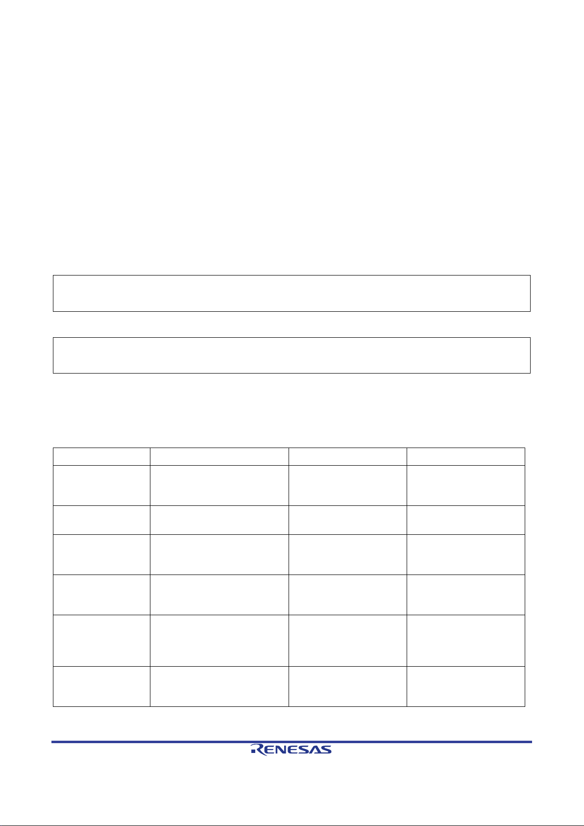
How to Use This Manual
Document Type
Description
Document Title
Document No.
Quick Start Guide
Provides simple instruction to
Quick Start Guide
R12QS0007EG
Schematics
Full detail circuit schematics
Hear-it! Solution Kit
R01UH0692EG
Hardware Manual
Provides technical details of
RX230 Group, RX231
R01UH0496EJ
BSP FIT application
Provides technical details of
Board Support Package
Module Using Firmware
R01AN1685EJ
DMACA FIT
Provides technical details of
DMA Co ntroller DMACA
R01AN2063EJ
CMT FIT
Provides technical details of
CMT Module Using
R01AN1856EU
1. Purpose and Target Readers
This manual is designed to provide the user with an understandi ng of the demonstrati on application, how to use
2
studio IDE to develop and debug software for the Hear-it! Sol ution Kit. It is intended for use rs designing code
e
on the Hear-it! Solution Kit, using the many different incorporated peripheral devices.
2
The manual comprises of step-by-step instruct ions to l oad and de bug a pr oject in e
to be a complete guide to software development on the Hear-it! Solution Kit. Further details of the RX231
microcontroller may be found in the RX231 Group Hardware Manual and within the provided demonstration
code.
Particular attention should be paid to the precautionary notes when using the manual. These notes occur
within the body of the text, at the end of each section, and in the Usage Notes section.
The revision history summarizes the locations of revisions and additions. It does not list all revisions. Refer
to the text of the manual for details.
studio, but does not intend
The following documents apply to the Hear-it! Solution Kit. Make sure to refer to the latest versions of these
documents. The newest versions of the documents listed may be obtained from the Renesas Electronics Web
site.
setup the solution kit and run
the first sample.
of Hear-it!
the RX231 MCU.
Schematics
Group User’s Manual:
Hardware
note
application note
how to integrate and use the
BSP FIT module.
how to integrate and use the
DMACA FIT module.
Integration Technology
Control Module Using
Firmware Integration
Technology
application note
R12UZ0012EG0110 Rev. 1.10 Page 4 of 34
Apr 03, 2017
how to integrate and use the
CMT FIT module.
Firmware Integration
Technology
Page 5

RSPI FIT
application note
Provides technical details of
RSPI Clock
R01AN1914EJ
SSI FIT application
Provides technical details of
SSI Module Using
R01AN2150EJ
USB host
Provides technical details of
USB peripheral driver FIT
USB Basic Mini Host
R01AN2166EJ
USB host CDC FIT
Provides technical details of
USB Host
R01AN2167EJ
USB host mass
Provides technical details of
USB Host Mass Storage
R01AN2169EJ
Open source FAT
Provides technical details of
Open Source FAT file
R20AN0038EJ
how to integrate and use the
RSPI FIT module.
synchronous Single
Master Control Module
Firmware Integration
Technology
note
peripheral driver
FIT application note
application note
storage class driver
FIT application note
file system FIT
application note
how to integrate and use the
SSI FIT module.
how to integrate and use the
module.
how to integrate and use the
USB host CDC FIT module.
how to integrate and use the
USB host mass storage class
driver FIT module.
how to integrate and use the
M3S-TFAT-Tiny FIT m odule.
Firmware Integration
Technology
and Peripheral Driver
(USB Mini Firmware)
Using Firmware
Integration Technology
Communication Device
Class Driver for USB
Mini Firmware Using
Firmware Integration
Technology
Class Driver for USB
Mini Firmware Using
Firmware Integration
Technology
System [M3S-TFATTiny] Module Firmware
Integration Technology
R12UZ0012EG0110 Rev. 1.10 Page 5 of 34
Apr 03, 2017
Page 6

2. List of Abbreviations and Acronyms
Abbreviation
Full Form
ADC
Analog-to-Digital Converter
BTL
Bridge-Tied Load
BPF
Band-Pass Filter
CAN
Controller Area Network
CDC
Communication Device Class
CMT
Compare Match Timer
CODEC
Coder-decoder
DAC
Digital-to-Analog Converter
DMA
Direct Memory Access
DMAC
Direct Memory Access Controller
DSP
Digital Signal Processor
FAT
File Allocation T able
FIR
Finite Impulse Response
FIT
Firmware Integration Technology
HPF
High-Pass Filter
I2S
Inter-IC Sound
ISR
Interrupt Service Routine
LPF
Low-Pass Filter
MCU
Microcontroller Unit
MTU
Multi-Function T i m er P ulse Unit
PCB
Printed Circuit Board
PCM
Pulse Code Modulation
PGA
Programmable Gain Amplifier
PMODTM
Peripheral Module
RAM
Random Access Memory
RFP
Renesas Flash Programmer
ROM
Read Only Memory
RSPI
Renesas Serial Peripheral Interface
RTC
Real Time Clock
SCI
Serial Communications Interface
SPI
Serial Peripheral Interface
SSI
Serial Sound Interface
USB
Universal Serial Bus
WAV
Waveform Audio File Format
R12UZ0012EG0110 Rev. 1.10 Page 6 of 34
Apr 03, 2017
Page 7

All trademarks and registered trademarks are the property of their respective owners.
R12UZ0012EG0110 Rev. 1.10 Page 7 of 34
Apr 03, 2017
Page 8

Table of Contents
1. Overview .......................................................................................................................... 10
1.1 Purpose .................................................................................................................................................... 10
2. Introduction ...................................................................................................................... 11
2.1 Target Device ........................................................................................................................................... 11
3. Description of Application Firmware ................................................................................. 12
3.1 USB Playback Sample ............................................................................................................................. 12
3.2 Audio Streaming Sample ......................................................................................................................... 13
4. Hardware Design ............................................................................................................. 14
4.1 Operating Check Conditions .................................................................................................................... 14
4.2 Hardware Configuration ........................................................................................................................... 15
4.2.1 RX231 Microcontroller .................................................................................................................... 15
4.2.2 Programmer/Debugger Connections ............................................................................................. 15
4.2.3 User Controls ................................................................................................................................. 15
4.2.4 USB Host Connection .................................................................................................................... 15
4.2.5 PMODTM Connectivity .................................................................................................................... 16
4.2.6 WM8983 CODEC ........................................................................................................................... 16
4.2.7 Power Supply ................................................................................................................................. 16
5. Embedded Firmware Application Samples ...................................................................... 17
5.1 Hardware Configuration ........................................................................................................................... 17
5.1.1 Switch Settings for Embedded E2-Lite Programmer/Debugger .................................................... 17
5.1.2 Jumper Settings ............................................................................................................................. 17
5.1.3 Resistor Modifications .................................................................................................................... 17
5.2 Starting e2 studio and Importing Sample Code ........................................................................................ 18
5.3 Software Configurations ........................................................................................................................... 20
5.3.1 Streaming Sample Application ....................................................................................................... 20
5.3.2 USB Playback Application .............................................................................................................. 21
5.4 Build Configuration ................................................................................................................................... 22
5.5 Running in Debug Mode .......................................................................................................................... 23
5.6 Running the Hear-it! Application Code ..................................................................................................... 23
6. Description of Software .................................................................................................... 24
6.1 USB Playback Sample ............................................................................................................................. 24
6.1.1 Operation ........................................................................................................................................ 24
6.1.2 PCM Data Transfer ........................................................................................................................ 24
R12UZ0012EG0110 Rev. 1.10 Page 8 of 34
Apr 03, 2017
Page 9

6.1.3 Volume Control ............................................................................................................................... 25
6.1.4 USB Device File Searching ............................................................................................................ 26
6.2 Audio Streaming Sample ......................................................................................................................... 27
6.2.1 Operation ........................................................................................................................................ 27
6.2.2 PCM Data Transfer – Audio Streaming Sample ............................................................................. 27
6.2.3 DSP FIR Filter ................................................................................................................................ 28
6.2.4 Volume Control ............................................................................................................................... 29
7. Additional Information ...................................................................................................... 30
R12UZ0012EG0110 Rev. 1.10 Page 9 of 34
Apr 03, 2017
Page 10

Hear-it! Solution Kit 1 Overview
1. Overview
1.1 Purpose
This Solution Kit is an evaluation tool for Renesas microcontrollers.
This manual describes the Hear-it! Solution Kit hardware and demonstration application
R12UZ0012EG0110 Rev. 1.10 Page 10 of 34
Apr 03, 2017
Page 11

Hear-it! Solution Kit 2 Introduction
2. Introduction
The Hear-it! Solution Kit is designed to demonstrate the cap ability of t he Renesas RX231 microco ntroller in low
cost audio processing applications. Digital filtering can be applied to an audio input source (3.5mm line-in or
optionally a Mic input) and the result output to 3.5mm speaker or line-out connection. A demonstration of audio
playback from a USB mass storage device connected to the USB Host connector is also provided. The singleboard PCB also incorporates an integrated E2-Lite debugger/programmer, a PMOD
of a display (supplied) and provides a flexible hardware and software platform to be used as a basis for further
developments.
This user manual has been written to help the user understand the sample code provided with the Hear-it! Kit.
It is intended to be read by those using the Hear-it! as a guide or starting point for their own applications.
Renesas Firmware Integration T echnol ogy (FIT) is used to initialise and drive hardware modul es that are needed
for this sample. Using FIT ensures the portability of this sample between different microcontrollers in the RX
family.
2.1 Tar get Device
RX231 100pin LFQFP package, 512K/64K ROM/RAM, Part number R5F52318ADFP
TM
interface for connection
R12UZ0012EG0110 Rev. 1.10 Page 11 of 34
Apr 03, 2017
Page 12

Hear-it! Solution Kit 3 Description of Application Firmware
Figure 3-1 : USB Audio Playback
Caution:
damage to the headphones may occur. Refer to section 4.2.6 for further information.
3. Description of Appli cation Firmware
The Hear-it! Solution Kit is supplied with 2 sample applications. One sample, rx231_usb_playback_demo, plays
audio files in wav format from a USB mass storage device connected to the USB Host connector, CN9. The
second sample, rx231_dsp_demo, demonstrates the application of digital FIR filtering to an audio st ream.
3.1 USB Playback Sample
This sample implements an audio player capable of rendering 48 kHz 16-bit WAV- PCM format file stored on a
USB device. A USB device can be attached to CN9 with a maximum of sixteen .wav files. Further details of the
configuration of the USB is detailed in section 4.2.4.
The .wav files will be displayed on the PMOD™ display and can be highlighte d and selected for audi o playbac k
using the on-board switch (SW3) and potentiomete r (R4 3).
2
Audio information from the USB is sent by DMA transfer in I
for digital to analogue conversion and output to speaker and/or headphone. Once a .wav file is selected and
has started playing, the on-board potentiometer can be used to control the output volume. This volume control
is implemented with an attenuation function in the sample application software, or optionally by configuring the
volume on the WM8983 CODEC IC. Figure 3-1 gives a holi stic outline the USB audio playback.
Headphones should be connected to the 3.5mm line-out connector CN5. Connector CN6 is designed to
connect to a speaker only. It is not recommended to attach headphones to speaker connection CN6, as
S format to the audio codec via the SSI interface
R12UZ0012EG0110 Rev. 1.10 Page 12 of 34
Apr 03, 2017
Page 13

Hear-it! Solution Kit 3 Description of Application Firmware
Figure 3-2 : Audio Streaming M ode
Caution:
damage to the headphones may occur. Refer to section 4.2.6 for further information.
3.2 Audio Streaming Sample
The second sample, rx231_dsp_demo, demonstrates the application of a DSP FIR filter on the left or right
channel of an incoming audio signal from the line-in or microphone inputs. The modified audio stream is then
transmitted to the audio codec via DMA and the SSI peripheral and then out to the speaker and/or headphones.
Figure 3-2 shows a holistic outline of the audio streaming. As with the USB playback demonstration, the volume
control is implemented with a software attenuation fun ction, with an option in the sourc e code for cont rol via the
codec directly. There further configuration available in the source code to select the left or right channel as the
input source, and the left, right or both channels as output source.
The output volume can be controlled by adjusting the potentiometer, R43. Switch SW3 cycles between the
different FIR filter profiles; Flat, High Pass, Low Pass, Band Pass where the audio is playing.
Headphones should be connected to the 3.5mm line-out connector CN5. Connector CN6 is designed to
connect to a speaker only. It is not recommended to attach headphones to speaker connection CN6, as
R12UZ0012EG0110 Rev. 1.10 Page 13 of 34
Apr 03, 2017
Page 14

Hear-it! Solution Kit 4 Hardware Design
Item
Description
Microcontroller used
RX231 (R5F52318ADFP)
Operating frequency
Maximum operating frequency – 54 MHz
Power Supply Operating Voltage
5.0Vdc
Integrated development environment
e2 studio version 5.3
Toolchain
Renesas RXC Toolchain v2.06
Board used
Hear-it! Solution Kit
Figure 4-1 : BTL Speaker Configuration
Left
Right
-
+
Left
Right
4. Hardware Design
• Hear-it! Solution Kit.
• 3.5mm line-in input audio jack (CN7).
• 3.5mm line-out output audio jack for headphones (CN5).
• 3.5mm audio jack for speaker connection (CN6). The output is set to drive a mono speaker in BTL
configuration. See Figure 4-1.
4.1 Operating Check Conditions
The sample code described in this user manual has been checked under the conditions listed in Table 4-1.
PCLKA : 54 MHz
PCLKD : 54 MHz
BCLK : 32 MHz
FCLK : 32 MHz
Table 4-1 : Operating Conditions
R12UZ0012EG0110 Rev. 1.10 Page 14 of 34
Apr 03, 2017
Page 15

Hear-it! Solution Kit 4 Hardware Design
4.2 Hardware Configuration
The Hear-it! Solution Kit hardware consists of the RX231 microcontroller and associated circuitry, a WM8983
TM
CODEC IC, a USB Host connector, embedded E2-Lite programmer/debugger, PMOD
connector and power
supply.
4.2.1 RX231 Microcontroller
The RX231 fitted to the Hear-it! PCB has the Renesas part number R5F52318ADFP. It is a 100pin LFQFP
package with 512kB Flash ROM, 64kB RAM and 8kB DataFlash. The 32 -bit CPU can be clocked at up to 54MHz
and supports single precision floating point operations. The RX231 microcontroller incorporates extensive
supporting peripherals such as DMA, multiple ti mers, mult iple communic ation s functions such as SS I, SCI , I
2
C,
SPI, CAN, 12-bit ADC and DAC, c apacitive touch-sensing.
The circuitry supporting the RX231 microcontroller consists of an 8MHz main oscillator, Real-Time-Clock
oscillator (RTC) (not fitted as standard), program mer/debugge r connections and a potentiom eter and switch f or
user input.
4.2.2 Programmer/Debugger Connections
By default the Hear-it! board uses the embedded E2-Lite programmer/debugger to access the RX231
microcontroller . There is provision to fit a 14-way connector (Samtec part number SAM_H TST-107-01-X-DV) to
support connection of an external E1 or E2-Lite programmer/debugger if required. If an external debugger is
used, the embedded E2-Lite debugger must be deactivated by setting it to ‘standalone’ mode, achieved by
setting both switches in the switch block SW1 to the ‘OFF’ position, see Figure 4-2.
Figure 4-2 : Debugger Isolating Switch SW1 in “Off” Position
4.2.3 User Controls
Inputs from the user are taken from the potentiometer R43, for up and down menu control and switch SW3, for
user selection. The potentiometer is read on the MCU’s ADC channel 0 (P4-0, pin 95). The reading, as a
percentage of the full scale, is used to determine which menu item is currently highlighted by t he user.
The momentary action switch, SW3 is conne cted to a hardware interrupt line I RQ1, (P3-1, pin 19). This pr ovides
an interrupt to handle switch presses with a minimum of CP U intervention. The switch is used to determine the
user’s selection in the current menu.
4.2.4 USB Host Connection
A USB Host connection is provided, for connection of a USB mass storage device on connector CN9. It is not
intended that this is used to supply significant power to any connected devices. It is recommended to keep the
current drawn to below 200mA.
R12UZ0012EG0110 Rev. 1.10 Page 15 of 34
Apr 03, 2017
Page 16

Hear-it! Solution Kit 4 Hardware Design
Vcc
0V
Backlight
Data
/Cmd
Reset
Not Used
Vcc
0V
SCK
RX
TX
Enable
6
5
4
3
2
1
12
11
10
9
8
7
CN2 PMODTM
Pin
Function
IC7 MCU Pin
IC7 MCU Port/Pin,
function
Schematic
Signal
1
Enable (Chip Select)
(Active Low)
17
P33, I/O
PMOD_CS
2
TX
53
PB7, SCI9 TX
TXD9
3
RX (Not used on display)
54
PB6, Not Used
RXD9
4
SCK
55
PB5, SCI9 SCK
SCK9
7
Not used on display
72
PE6, Not Used
IRQ6
8
Reset
71
PE7, I/O
IRQ7
9
Data/Cmd
75
PE3, I/O
PE3
10
Backlight
74
PE4, I/O
PE4
Caution:
damage to the headphones may occur.
4.2.5 PMODTM Connectivity
The Hear-it! Solution kit is distributed with a 128x128 colour display , driven from the PMOD
Communications between the MCU (IC7) and the PMOD
in SPI transmit only mode, plus various other signal s to manage device select, reset and backlight control.
The connection of the display to the microcontroller is shown in Figure 4-3 and Table 4-2. Note that the pinout
for the PMOD
left then on the right, as per the PMOD
TM
connector is not made in the standard fashion of left to right ascending, but ascending on the
Figure 4-3 : Connection Diagram for PMOD
TM
standard.
TM
display are made by the on-board SCI9 peripheral,
TM
display on CN2
TM
connecto r on CN2.
Table 4-2 : Connection Details for PMODTM Display on CN5
4.2.6 WM8983 CODEC
The Hear-it! Solution Kit board incorporates a Cirrus Logic WM8983 Stereo CODEC with speaker driver. This
provides Line-In and MIC inputs and outputs for a headphone and s peaker (up to 1W). The MIC input connector
CN8 is not fitted by default on the PCB. If it is required then the recommended part is SJ-3506-SMT-TR from
CUI. Audio data is transferred to and received from the RX231 MCU by SSI interface, and a separate SPI
connection is used to configure the CODEC, on SCI8 of the RX23 1 M CU.
The audio clock for the CODEC is a 12.288MHz oscillator, OSC1, which is also fed to the RX231 MCU on pin
16, P34 for the SSI interface.
Headphones should be connected to the 3.5mm line-out connector CN5. Connector CN6 is designed to
connect to a speaker only. It is not recommended to attach headphones to speaker connection CN6, as
4.2.7 Power Supply
The Hear-it! Solution Kit can be powered either from the embedded programmer/debugger USB-mini function
connector CN4, or by a 5V supply connected to CN1, with a standard centre-positive barrel connector. The
connection from CN1 is intended to provide the lowest noise solution. No modification or configuration is
required to use either source. A 3.3V supply for the MCU, PMOD
The RX231 MCU is supplied through header JP1/R12, to allow the current consumption of the RX231 MCU to
be evaluated.
TM
and CODEC is provided by regulator IC1.
R12UZ0012EG0110 Rev. 1.10 Page 16 of 34
Apr 03, 2017
Page 17

Hear-it! Solution Kit 5 Embedded Firmware Application
SW1-1
SW1-2
State
ON
ON
SW1-1
SW1-2
State
OFF
OFF
5. Embedded Firmware Application Samples
The Hear-it! Solution Kit is shipped with the application firmware pre-programmed to run the ‘streaming’
demonstration configured to use the left channel. T he application f irmware can be prog rammed or run in debug
mode via the embedded E2-Lite programmer/debugger and the e
Flash Programmer (RFP) on the PC.
• Fit the PMOD
TM
display to the board on connector CN2.
• In order to run standalone, ensure that switch SW1 is configured for standalone mode. Refer to Table
5-2 f or the correct settings. Make the audio connections as requi red and then apply power by connecting
the mini-USB function connector CN4 to the PC or by connecting a 5V supply to the centre-positive
barrel connector CN1 if desired.
• For debug or programming, refer to Table 5-1 for the correct settings for switch SW1. Make the required
audio connections. Connect the mini-USB function connector CN4 to the host PC usi ng the supplied
cable. The Hear-it! Solution kit is now ready for progr am m ing/debug operations
When running the ‘streaming’ demo, ensure potentiometer R43 is turned fully anti-clockwise before operating
the demonstration. This potentiometer controls the volume. When playing audio through the device slowly turn
clockwise to listen to the audio at the appropriate volume.
5.1 Hardware Configuration
5.1.1 Switch Settings for Embedded E2-Lite Programmer/Debugger
For standalone operation or if using external E1 debugger, ensure that SW1 has the settings shown in Table
5-2. For programming or debugging, the SW1 should be set as described in Table 5-1.
2
studio IDE or programmed by the Renesas
Table 5-1 : SW1 Configuration for Programming/Debug Operation
Table 5-2 : SW1 Configuration for Standalone Operation
5.1.2 Jumper Settings Ensure that the following jumpers are NOT connected.
• JP1
• JP2
5.1.3 Resistor Modifications
No resistor modification to the default Hear-it! Solution Kit is required.
R12UZ0012EG0110 Rev. 1.10 Page 17 of 34
Apr 03, 2017
Page 18

Hear-it! Solution Kit 5 Embedded Firmware Application
Start e2 studio by selecting it from the
The e2 studio welcome splash screen will
Once the environment has initialized, right click
5.2 Starting e2 studio and Importing Sample Code
Windows™ Start Menu. The first dialog box to
appear will be the Workspace Launcher.
Click ‘Browse’ and select a suitable location to
store your workspace, using the ‘Make New
Folder’ option as necessary. Click ‘OK’.
appear. Click the ‘Go to the e2 studio workbench’
arrow button on the far right (circled in the
screenshot opposite).
in the ‘Project Explorer’ window and select
‘Import…’
R12UZ0012EG0110 Rev. 1.10 Page 18 of 34
Apr 03, 2017
Page 19

Hear-it! Solution Kit 5 Embedded Firmware Application
The Import dialog box will be shown. Expand the
‘General’ folder icon, and select ‘Existing
The Import dialog box will allow you to specify
The projects will be imported into the workspace:
Projects into Workspace’, then click ‘Next’.
projects to import. Click the ‘Select archive file:’
button, then click “Browse…” and locate the
following directory:
C:\Renesas\Workspace\Y-HEAR-IT-RX231
Select the file ‘rx231_dsp_demo.zip’ and click
‘Open’. Ensure that both projects are selected
and then click ‘Finish’.
R12UZ0012EG0110 Rev. 1.10 Page 19 of 34
Apr 03, 2017
Page 20

Hear-it! Solution Kit 5 Embedded Firmware Application
5.3 Software Configurations
5.3.1 Streaming Sample Application
The Hear-it! Streaming sample application, “rx231_dsp_demo” has various configurable options. These are
located in the source file main.h.
5.3.1.1 Input Channel Selection
The input audio channel to be used for t he DSP p rocessing can be configured by sett ing the AUDIO_CHANNEL
#define to the LEFT channel or the RIGHT channel. This can be seen in Figure 5-1 where AUDIO_CHANNEL
is set to LEFT (default setting).
Figure 5-1 : Streaming Input Channel Configuration
5.3.1.2 Output Channel Selection
The application can be configured to select the channel or combination of channels to use for the processed
audio output. The default setting is for both channels to be used as the output.
Figure 5-2 : Streaming Output Channel Configuration
5.3.1.3 Volume Control Scheme
The sample application by default uses a software attenuation fun ction to control the v olume of the audio si gnal.
It is possible to configure the application to use the CODEC to control the volume. In order to select this,
uncomment the following #define
Figure 5-3 : Streaming Volume Configuration Selection
R12UZ0012EG0110 Rev. 1.10 Page 20 of 34
Apr 03, 2017
Page 21

Hear-it! Solution Kit 5 Embedded Firmware Application
5.3.1.4 Microphone Input
The microphone input, CN8 is not fitted to the Hear-it! boar d by def ault. If t he microphone input is t o be used i n
the streaming application, the CODEC must be configured to enable its internal PGAs (Programmable Gain
Amplifiers) in order to allow the audio signal f rom the MIC input to be used.
This is achieved by un-commenting the #define ENABLE_MICROPHONE, in the main.h file.
Figure 5-4 : Enabling the MIC input CN8
5.3.2 USB Playback Application
5.3.2.1 File Selection
This sample allows the user to select .wav f iles from a USB drive att ached to the USB Host conne ctor CN9 and
to play the audio on the speaker/headphones. The USB drive must contain a folder called ‘Music’. The Music
folder may hold a maximum of 16 .wav files. Ensure the USB drive contains the ‘Music’ f older as seen in the
figure below and contains .wav files. The available .wav files will be shown on the display conne cted on PMOD
TM
connector CN2. Use pot R43 and switch SW3 to select the desired track to play.
Figure 5-5 : Music Folder on USB Drive
5.3.2.2 Volume Control Scheme
The sample application by default uses a software attenuati on function to control the volume of the audio signal.
It is possible to configure the application to use the CODEC to control the volume. In order to select this,
uncomment the following #define in main.h
Figure 5-6 : Streaming Volume Configuration Selection
R12UZ0012EG0110 Rev. 1.10 Page 21 of 34
Apr 03, 2017
Page 22

Hear-it! Solution Kit 5 Embedded Firmware Application
Click the top level ‘rx231_dsp_demo’ or
then the
then set the current build
5.4 Build Configuration
The e2 studio project has two build configurations for each sample: ‘HardwareDebug’ and ‘Release’:
HardwareDebug
This Build Mode has all optimisation turned off, and pr ovides full debug information. This is the best configuration
to use whilst developing code as C code execution will be linear .
Release
This Build Mode has optimisation turned on, and provides no debug information. The C code execution may
appear to be out of order, due to the way compiler optimises the code. This build configuration is intended for
final ROM-programmable code.
By default, the project is configured to HardwareDebug build configuration.
Setting the build configuration
‘rx231_usb_playback_demo’ folder,
arrow next to the build button (hammer
icon), and select the required option.
e2 studio will
configuration to the selected option and build
accordingly.
R12UZ0012EG0110 Rev. 1.10 Page 22 of 34
Apr 03, 2017
Page 23

Hear-it! Solution Kit 5 Embedded Firmware Application
Click the arrow next to the debug
The ‘Debug Configurations’ dialog box will appear .
The examples for the streaming
Click the ‘Debug’ but ton t o continu e. e2 studio will
A firewall warning may be displayed for ‘e 2-serverAfter downloading the code a dialog box will
Click ‘Remember my
5.5 Running in Debug Mode
button (bug icon). Select ‘Debug
Configurations
Click the small arrow next to the ‘Renesas GDB
Hardware Debugging’ option.
The debug configurations for each project will
appear.
application rx231_dsp_demo are shown to the
right. Select the entry for the required debug
configuration.
If the configuration has been built and the required
executable is present, the ‘Debug’ button in the
bottom right of the window will be active.
now connect to the debugger and download the
code to the target.
gdb.exe’. Check the ‘Private networks, such as
my home or work network’ box and click ‘Allow
access’.
A user account control dialog may be displayed.
Enter the administrator password and click ‘Yes’.
appear asking if you would like to switch to the
‘Debug perspective’.
decision’ to prevent t his dialog box from appearing
in future, then click ‘Yes’.
e2 studio will load the new perspective, which is
optimised for debugging.
5.6 Running the Hear-it! Application Code
Once the code has been downloaded, click the ‘Resume’ button to run the code to the main function. The
main function is the default program entry point. The program counter will stop on the first instruction in the
main function.
Click the ‘Resume’ button in the ‘Debug’ perspe ct i ve to run the rest of the code.
Follow the instructions on the PMOD
TM
R12UZ0012EG0110 Rev. 1.10 Page 23 of 34
Apr 03, 2017
display.
Page 24

Hear-it! Solution Kit 6 Description of Software
Step
USB operation
memcpy operation
DMAC0 operation
1
data read into rx buffer (c)
rx buffer (b) to tx buffer (b)
tx buffer (a) to CODEC
2
data read into rx buffer (a)
rx buffer (c) to tx buffer (c)
tx buffer (b) to CODEC
3
data read into rx buffer (b)
rx buffer (a) to tx buffer (a)
tx buffer (c) to CODEC
Tx Buffer
Rx Buffer
(a)
(b)
(c)
(a)
(b)
(c)
USB
CODEC
memcpy
DMAC0 (SSI)
2
3
1
2
3 1 1
2
3
Caution:
damage to the headphones may occur. Refer to section 4.2.6 for further information.
6. Description of Software
The choice between USB audio playback and streaming from line-i n or MIC input is achieved through conditional
compilation of the application software project. Refer to section 5.3 for details of the conditional compilation
required to change operating modes.
6.1 USB Playback Sample
6.1.1 Operation
After reset, the sample waits for a USB mass storage device to be connected to the USB connector CN9. Once
this occurs, the user is first pre sented with a li st of available .wav files in the ‘Music’ folder. The user can choose
an audio file from the list by using the potentiometer and pressing SW3 to select. Once t he file has been selected,
file playback is paused so that the user can adjust the volume to a suitable level, using the pot R43 (as the pot
has just been used to select the file, the volume may start at a surprising level). Pressing switch SW3 starts
playback of the file, and SW3 can then be used to pause or resume during the file playback. The pot R43 can
be used to control the volume of the speaker ( and headphones if fitted). Visual indication of s tat us, v olume an d
progress are shown on the display.
Headphones should be connected to the 3.5mm line-out connector CN5. Connector CN6 is designed to
connect to a speaker only. It is not recommended to attach headphones to speaker connection CN6, as
6.1.2 PCM Data Transfer
The transfer of PCM data from the .wav file on the USB drive to the audio CODEC is managed by a receive
buffer for data pulled from the USB drive and a corresponding transmit buffer to send data to the CODEC via
the SSI interface. The Renesas TFAT FIT module is used to transfer data from the USB to the receive buffer.
Internally, data is transferred from receive buffer to transmit buffer by a memcpy function. The 16-bit PCM data
in the transmit buffer is sent to the CODEC via the SSI interface by the DMAC microcontroller peripheral,
matching the sampling frequency of the wav files at 48kHz.
In order to achieve seamless playback each buffer is divided into 3 sub-blocks. The data being transferred into
a buffer is always being placed into a different sub-block to the data being transferred out of the buffer to the
next stage. The changeover process for updating the activ e read/writ e blocks is manag ed in the DMAC 0 end of
transfer interrupt, which is the slowest part of the chain from USB to CODEC. In this way, the CODEC has a
continuous supply of data.
Figure 6-1 shows this transfer graphically. Table 6-1 shows the operations in progress at each step.
Figure 6-1 : USB Playback Mode Buffer Processing Overview
Table 6-1 : USB Playback Mode Buffer Operations
R12UZ0012EG0110 Rev. 1.10 Page 24 of 34
Apr 03, 2017
Page 25

Hear-it! Solution Kit 6 Description of Software
SSITX empty
interrupt
Transfer
Interrupt
DMAC0
isr_dmac_wr ()
Main routine: main()
Transmit buffer:
Receive buffer:
g_pcm_buffer_rx
SSI
Next
information
Next
information
WM8983
CODEC
Data
Operation
Interrupt
usb_data_fetch
Data fetch from USB
Software
The SSITX empty interrupt triggers DMAC0 channel to transfer data from the active tx buffer to the CODEC.
The DMAC0 transfer end interrupt handler updates the active sub-blocks for the g_pcm_buffer_tx and
g_pcm_buffer_rx buffers. It also requests more data to be read from t he USB device t o be stored at the current
receive buffer and triggers to transfer of data from the rx buffer to the tx buffer. The process is illustrated in
Figure 6-2.
flag
Attenuation
Function for
Volume Control
pcm_buffer_tx
End
pcm_buffer_rx
Module
g_pcm_buffer_tx
Figure 6-2 : Data Tra nsf er Scheme in USB Playback Mode
6.1.3 Volume Control
The volume of the audio signal is controlled by default by an at tenuation function in software. This is called when
the audio block is transferred to the transmit buffer prior to transmission to the CODEC for output. Optionally,
the volume can be controlled directly by the CODEC, based on configuration in the source code. See section
5.3.2.2 for further details.
R12UZ0012EG0110 Rev. 1.10 Page 25 of 34
Apr 03, 2017
Page 26

Hear-it! Solution Kit 6 Description of Software
0:
Music
Directory 2
Directory 3
Directory 4
Audio1.wav
Audio2.wav
Audio3.wav
Audio4.wav
Files and Directories on Mass Storage
Left Child Right Sibling Representation of Files in Mass
Left child
Left child
Right sibling
0:
Music
Directory 2
Directory 3
Directory 4
Audio1.wav
Audio2.wav
Audio3.wav
Audio4.wav
Figure 6-3 : Representation of Files in Mass Storage Device
6.1.4 USB Device File Searching
The sample currently searches the root directory of the USB device for a folder named ‘Music’. If the folder
exists, the sample searches for ‘.wav’ files within the ‘Music’ folder and stores the file names in a RA M in a ‘left
child right sibling’ data structure. Currently, the sample does not search directories other than the root and the
‘Music’ directory. It simply adds the found ‘.wav’ files in ‘Music’ folder as “right-siblings” of the first found ‘.wav’
file. However, the data structure can easily be adapted to implement a more complex search tool that includes
searching multiple directories.
Storage
R12UZ0012EG0110 Rev. 1.10 Page 26 of 34
Apr 03, 2017
Page 27

Hear-it! Solution Kit 6 Description of Software
Step
DMAC1 operation
DSP filter operation
DMAC0 operation
1
data read into rx buffer (c)
rx buffer (b) to tx buffer (b)
tx buffer (a) to CODEC
2
data read into rx buffer (a)
rx buffer (c) to tx buffer (c)
tx buffer (b) to CODEC
3
data read into rx buffer (b)
rx buffer (a) to tx buffer (a)
tx buffer (c) to CODEC
(a)
Rx Buffer
(a)
Tx Buffer
DSP Filter
Operation
DMAC0 (SSI)
1 2 3
(b)
(b)
1 3 1
(c)
(c)
2
DMAC1 (SSI)
3
2
Caution:
damage to the headphones may occur. Refer to section 4.2.6 for further information.
6.2 Audio Streaming Sample
6.2.1 Operation
After reset, the sample sets up the display and begi ns streaming of audi o from the sel ected input channel to the
output. The user can switch between the available FIR filter profiles by pressing the button SW3. The pot R43
can be used to control the volume of the speaker (and headphones if fitted). Visual indication of status and
volume are shown on the display.
Headphones should be connected to the 3.5mm line-out connector CN5. Connector CN6 is designed to
connect to a speaker only. It is not recommended to attach headphones to speaker connection CN6, as
6.2.2 PCM Data Transfer – Audio Streaming Sample
16-bit PCM data is generated by the CODEC from the input source and transferred to the receive buffer from
the RX231 SSI(rx) peripheral by DMAC channel 1. The received data is then passed through the DSP filter to
the transmit buffer. This data is then transmitted to the CODEC by DMAC0 and the RX231 SSI(tx) peripheral
for output to speaker/line-out. The sampling frequency for the PCM data is set to 24kHz.
In order to achieve seamless playback each buffer is divided into 3 sub-blocks. The data being transferred into
a buffer is always being placed into a different sub-block to the data being transferred out of the buffer to the
next stage. In this way a continuous supply of data can be maintained.
Figure 6-4 shows this transfer graphically and Table 6-2 shows the operations in progress at each step.
CODEC
IN
Figure 6-4 : Audio Streaming Mode Buffer Processing Overview
CODEC
OUT
Table 6-2 : Audio Streaming Mode Buffer Operations
PCM data transfer between the MCU and the audio Codec is handled by the SSI module and two DMAC
channels. The SSITX empty and SSIRX full interrupts trigger DMAC0 and DMAC1 channels respectively. The
process is illustrated in Figure 6-5.
R12UZ0012EG0110 Rev. 1.10 Page 27 of 34
Apr 03, 2017
Page 28

Hear-it! Solution Kit 6 Description of Software
FLAT
coef_flat_i32.h
LPF
coef_lpf1k_i32.h
HPF
coef_hpf1500_i32.h
BPF
coef_bpf_200_8000_i32.h
Transfer
end
interrupt
SSIRX full
interrupt
SSITX empty
Transfer
isr_dmac_wr
Main routine: main()
Transmit buffer:
Receive
SSI
Start DSP transfer
WM8983
Data
Operation
Interrupt
DMAC0
DMAC1
isr_dmac_rd ()
S/w attenuation
function
Update
Update
DSP FIR
Filter
Tx Buffer
pcm_buffer_tx
buffer:
pcm_buffer_rx
Rx Buffer
end
interrupt
interrupt
Module
6.2.3 DSP FIR Filter
As seen in Figure 6-5, the selected DSP FIR filter profile is applied to the sampled audio information when it is
transferred from the receive buff er pcm_buf fer_ rx to the tran smit buf fer pcm _buf fer_tx . There are 4 pre -set filter
profiles; FLAT, LPF, HPF and BPF, defined for a sampling frequency of 24kHz.
These filter profiles are defined in the following files, located in the r_dsp_fir subfolder:
These profiles are used to initialise the DSP fir filter, which is then called repeatedly to act on the audio
information being transferred, in the file r_d sp_fir.c.
For further information concerning the DSP filter and its API, refer to the Renesas document R01UW0128ES
which is located within the DSP Library c-source download on the Renesas website.
Various tools are available for creating FIR filter profiles on the internet, but it is beyond the scope of this
document to investigate this further.
R12UZ0012EG0110 Rev. 1.10 Page 28 of 34
Apr 03, 2017
Figure 6-5 : Data Tra nsf er Scheme in Audio Streaming Mode
Page 29

Hear-it! Solution Kit 6 Description of Software
6.2.4 Volume Control
The volume of the audio signal is controlled by default by an at tenuation function in software. This is called when
the audio block is transferred to the transmit buffer prior to transmission to the CODEC for output. Optionally,
the volume can be controlled directly by the CODEC, based on configuration in the source code. See section
5.3.1.3 for further details.
R12UZ0012EG0110 Rev. 1.10 Page 29 of 34
Apr 03, 2017
Page 30

Hear-it! Solution Kit 7 Additional Information
For details on how to use e2 studio, refer to
studio, then
selecting Help > Help Contents from the
7. Additional Information
Technical Support
the help file by opening e2
menu bar.
For information about the RX231 Group microcontrollers refe r t o the RX231 Group Hardware Manual.
For information about the RX assembly language, refer to the RX Family Software Manual.
Technical Contact Details
Please refer to the contact details listed in section 9 of the “Quick Start Guide”.
General information on Renesas Microcontrollers can be found on the Renesas website at:
http://www.renesas.com
Trademarks
All brand or product names used in this manual are trademarks or registered trademarks of their respective
companies or organisations.
Copyright
This document may be, wholly or partially, subject to change without notice. All rights reserved. Duplication of
this document, either in whole or part is prohibited wit hout the written permission of Rene sas Electronics Europe
Limited.
© 2017 Renesas Electronics Europe Limited. All rights reserved.
© 2017 Renesas Electronics Corporation. All rights reserved.
© 2017 Renesas System Design Co., Ltd. All rights reserved.
R12UZ0012EG0110 Rev. 1.10 Page 30 of 34
Apr 03, 2017
Page 31

Page
Summary
Revision History Hear-it! Solution Kit User’s Manual
Rev. Date Description
1.00 Nov 08, 2016 Initial Issue
1.10 Apr 03, 2017 Updated with application code
Page 32

Hear-it! Solution Kit: User’s Manual
Publication Date: Rev. 1.00 Nov 08, 2016
Rev. 1.10 Apr 03, 2017
Published by: Renesas Electronics Corporation
Page 33

Renesas Electronics America Inc.
2801 Scott Boulevard Santa Clara, CA 95050-2549, U.S.A.
Tel: +1-408-588-6000, Fax: +1-408-588-6130
Renesas Electronics Canada Limited
9251 Yonge Street, Suite 8309 Richmond Hill, Ontario Canada L4C 9T3
Tel: +1-905-237-2004
Renesas Electronics Europe Limited
Dukes Meadow, Millboard Road, Bourne End, Buckinghamshire, SL8 5FH, U.K
Tel: +44-1628-585-100, Fax: +44-1628-585-900
Renesas Electronics Europe GmbH
Arcadiastrasse 10, 40472 Düsseldorf, Germany
Tel: +49-211-6503-0, Fax: +49-211-6503-1327
Renesas Electronics (China) Co., Ltd.
Room 1709, Quantum Plaza, No.27 ZhiChunLu Haidian District, Beijing 100191, P.R.China
Tel: +86-10-8235-1155, Fax: +86
-10-8235-7679
Renesas Electronics (Shanghai) Co., Ltd.
Unit 301, Tower A, Central Towers, 555 Langao Road, Putuo District, Shanghai, P. R. China 200333
Tel: +86-21-2226-0888, Fax: +86-21-2226-0999
Renesas Electro
nics Hong Kong Limited
Unit 1601-1611, 16/F., Tower 2, Grand Century Place, 193 Prince Edward Road West, Mongkok, Kowloon, Hong Kong
Tel: +852
-2265-6688, Fax: +852 2886-9022
Renesas Electronics Taiwan Co., Ltd.
13F, No. 363, Fu Shing North Road, Taipei 10543, Taiwan
Tel: +886-2-8175-9600, Fax: +886 2-8175-9670
Renesas Electronics Singapore Pte. Ltd.
80 Bendemeer Road, Unit #06-02 Hyflux Innovation Centre, Singapore 339949
Tel: +65
-6213
-0200, Fax: +65-6213
-0300
Renesas Electronics Malaysia Sdn.Bhd.
Unit 1207, Block B, Menara Amcorp, Amcorp Trade Centre, No. 18, Jln Persiaran Barat, 46050 Petaling Jaya, Selangor Darul Ehsan, Malaysia
Tel: +60-3-7955-9390, Fax: +60-3-7955-9510
Renesas Electronics India Pvt. Ltd.
No.777C, 100 Feet Road, HAL II Stage, Indiranagar, Bangalore, India
Tel: +91-80-67208700, Fax: +91-80-67208777
Renesas Electronics Korea Co., Ltd.
12F., 234 Teheran-ro, Gangnam-Gu, Seoul, 135-080, Korea
Tel: +82-2-558-3737, Fax: +82-2-558-5141
© 2017 Renesas Electronics Corporation. All rights reserved.
Colophon 4.1
Page 34

RX231 Group
R12UZ0012EG0110
 Loading...