

Page 1

All information contained in these materials, including products and product specifications,
represents information on the product at the time of publication and is subject to change by
Renesas Electronics Corp. without notice. Please review the latest information published by
Renesas Electronics Corp. through various means, including the Renesas Electronics Corp.
website (http://www.renesas.com).
Cover
Bluetooth Low Energy Protocol Stack
Basic Package
User’s Manual
Rev.1.03 Mar 2021
32
RENESAS MCU
RX Family / RX200 Series / RX23W Group
User’ s Manual
www.renesas.com
Page 2

© 2021 Renesas Electronics Corporation. All rights reserved.
Notice
1. Descriptions of circuits, software and other related information in this document are provided only to illustrate the operation of semiconductor products
and application examples. You are fully responsible for the incorporation or any other use of the circuits, software, and information in the design of your
product or system. Renesas Electronics disclaims any and all liability for any losses and damages incurred by you or third parties arising from the use of
these circuits, software, or information.
2. Renesas Electronics hereby expressly disclaims any warranties against and liability for infringement or any other claims involving patents, copyrights, or
other intellectual property rights of third parties, by or arising from the use of Renesas Electronics products or technical information described in this
document, including but not limited to, the product data, drawings, charts, programs, algorithms, and application examples.
3. No license, express, implied or otherwise, is granted hereby under any patents, copyrights or other intellectual property rights of Renesas Electronics or
others.
4. You shall be responsible for determining what licenses are required from any third parties, and obtaining such licenses for the lawful import, export,
manufacture, sales, utilization, distribution or other disposal of any products incorporating Renesas Electronics products, if required.
5. You shall not alter, modify, copy, or reverse engineer any Renesas Electronics product, whether in whole or in part. Renesas Electronics disclaims any
and all liability for any losses or damages incurred by you or third parties arising from such alteration, modification, copying or reverse engineering.
6. Renesas Electronics products are classified according to the following two quality grades: “Standard” and “High Quality”. The intended applications for
each Renesas Electronics product depends on the product’s quality grade, as indicated below.
"Standard": Computers; office equipment; communications equipment; test and measurement equipment; audio and visual equipment; home
electronic appliances; machine tools; personal electronic equipment; industrial robots; etc.
"High Quality": Transportation equipment (automobiles, trains, ships, etc.); traffic control (traffic lights); large-scale communication equipment; key
financial terminal systems; safety control equipment; etc.
Unless expressly designated as a high reliability product or a product for harsh environments in a Renesas Electronics data sheet or other Renesas
Electronics document, Renesas Electronics products are not intended or authorized for use in products or systems that may pose a direct threat to
human life or bodily injury (artificial life support devices or systems; surgical implantations; etc.), or may cause serious property damage (space system;
undersea repeaters; nuclear power control systems; aircraft control systems; key plant systems; military equipment; etc.). Renesas Electronics disclaims
any and all liability for any damages or losses incurred by you or any third parties arising from the use of any Renesas Electronics product that is
inconsistent with any Renesas Electronics data sheet, user’s manual or other Renesas Electronics document.
7. No semiconductor product is absolutely secure. Notwithstanding any security measures or features that may be implemented in Renesas Electronics
hardware or software products, Renesas Electronics shall have absolutely no liability arising out of any vulnerability or security breach, including but not
limited to any unauthorized access to or use of a Renesas Electronics product or a system that uses a Renesas Electronics product. RENESAS
ELECTRONICS DOES NOT WARRANT OR GUARANTEE THAT RENESAS ELECTRONICS PRODUCTS, OR ANY SYSTEMS CREATED USING
RENESAS ELECTRONICS PRODUCTS WILL BE INVULNERABLE OR FREE FROM CORRUPTION, ATTACK, VIRUSES, INTERFERENCE,
HACKING, DATA LOSS OR THEFT, OR OTHER SECURITY INTRUSION (“Vulnerability Issues”). RENESAS ELECTRONICS DISCLA IMS ANY AND
ALL RESPONSIBILITY OR LIABILITY ARISING FROM OR RELATED TO ANY VULNERABILITY ISSUES. FURTHERMORE, TO THE EXTENT
PERMITTED BY APPLICABLE LAW, RENESAS ELECTRONICS DISCLAIMS ANY AND ALL WARRANTIES, EXPRESS OR IMPLIED, WITH
RESPECT TO THIS DOCUMENT AND ANY RELATED OR ACCOMPANYING SOFTWARE OR HARDWARE, INCLUDING BUT NOT LIMITED TO THE
IMPLIED WARRANTIES OF MERCHANTABILITY, OR FITNESS FOR A PARTICULAR PURPOSE.
8. When using Renesas Electronics products, refer to the latest product information (data sheets, user’s manuals, application notes, “General Notes for
Handling and Using Semiconductor Devices” in the reliability handbook, etc.), and ensure that usage conditions are within the ranges specified by
Renesas Electronics with respect to maximum ratings, operating power supply voltage range, heat dissipation characteristics, installation, etc. Renesas
Electronics disclaims any and all liability for any malfunctions, failure or accident arising out of the use of Renesas Electronics products outside of such
specified ranges.
9. Although Renesas Electronics endeavors to improve the quality and reliability of Renesas Electronics products, semiconductor products have specific
characteristics, such as the occurrence of failure at a certain rate and malfunctions under certain use conditions. Unless designated as a high reliability
product or a product for harsh environments in a Renesas Electronics data sheet or other Renesas Electronics document, Renesas Electronics products
are not subject to radiation resistance design. You are responsible for implementing safety measures to guard against the possibility of bodily injury,
injury or damage caused by fire, and/or danger to the public in the event of a failure or malfunction of Renesas Electronics products, such as safety
design for hardware and software, including but not limited to redundancy, fire control and malfunction prevention, appropriate treatment for aging
degradation or any other appropriate measures. Because the evaluation of microcomputer software alone is very difficult and impractical, you are
responsible for evaluating the safety of the final products or systems manufactured by you.
10. Please contact a Renesas Electronics sales office for details as to environmental matters such as the environmental compatibility of each Renesas
Electronics product. You are responsible for carefully and sufficiently investigating applicable laws and regulations that regulate the inclusion or use of
controlled substances, including without limitation, the EU RoHS Directive, and using Renesas Electronics products in compliance with all these
applicable laws and regulations. Renesas Electronics disclaims any and all liability for damages or losses occurring as a result of your noncompliance
with applicable laws and regulations.
11. Renesas Electronics products and technologies shall not be used for or incorporated into any products or systems whose manufacture, use, or sale is
prohibited under any applicable domestic or foreign laws or regulations. You shall comply with any applicable export control laws and regulations
promulgated and administered by the governments of any countries asserting jurisdiction over the parties or transactions.
12. It is the responsibility of the buyer or distributor of Renesas Electronics products, or any other party who distributes, disposes of, or otherwise sells or
transfers the product to a third party, to notify such third party in advance of the contents and conditions set forth in this document.
13. This document shall not be reprinted, reproduced or duplicated in any form, in whole or in part, without prior written consent of Renesas Electronics.
14. Please contact a Renesas Electronics sales office if you have any questions regarding the information contained in this document or Renesas
Electronics products.
(Note1) “Renesas Electronics” as used in this document means Renesas Electronics Corporation and also includes its directly or indirectly controlled
subsidiaries.
(Note2) “Renesas Electronics product(s)” means any product developed or manufactured by or for Renesas Electronics.
(Rev.5.0-1 October 2020)
Corporate Headquarters
Contact information
TOYOSU FORESIA, 3-2-24 Toyosu,
Koto-ku, Tokyo 135-0061, Japan
www.renesas.com
For further information on a product, technology, the most up-to-date
version of a document, or your nearest sales office, please visit:
www.renesas.com/contact/.
Trademarks
Renesas and the Renesas logo are trademarks of Renesas
Electronics Corporation.
The Bluetooth® word mark and logos are registered trademarks
owned by Bluetooth SIG, Inc. and any use of such marks by Renesas
Electronics Corporation is under license. All trademarks and
registered trademarks are the property of their respective owners.
Page 3

General Precautions in the Handling of Microprocessing Unit and Microcontroller Unit Products
The following usage notes are applicable to all Microprocessing unit and Microcontroller unit products from Renesas. For detailed usage notes on the
products covered by this document, refer to the relevant sections of the document as well as any technical updates that have been issued for the products.
1. Precaution against Electrostatic Discharge (ESD)
A strong electrical field, when exposed to a CMOS device, can cause destruction of the gate oxide and ultimately degrade the device operation. Steps
must be taken to stop the generation of static electricity as much as possible, and quickly dissipate it when it occurs. Environmental control must be
adequate. When it is dry, a humidifier should be used. This is recommended to avoid using insulators that can easily build up static electricity.
Semiconductor devices must be stored and transported in an anti-static container, static shielding bag or conductive material. All test and measurement
tools including work benches and floors must be grounded. The operator must also be grounded using a wrist strap. Semiconductor devices must not be
touched with bare hands. Similar precautions must be taken for printed circuit boards with mounted semiconductor devices.
2. Processing at power-on
The state of the product is undefined at the time when power is supplied. The states of internal circuits in the LSI are indeterminate and the states of
register settings and pins are undefined at the time when power is supplied. In a finished product where the reset signal is applied to the external reset
pin, the states of pins are not guaranteed from the time when power is supplied until the reset process is completed. In a similar way, the states of pins in
a product that is reset by an on-chip power-on reset function are not guaranteed from the time when power is supplied until the power reaches the level
at which resetting is specified.
3. Input of signal during power-off state
Do not input signals or an I/O pull-up power supply while the device is powered off. The current injection that results from input of such a signal or I/O
pull-up power supply may cause malfunction and the abnormal current that passes in the device at this time may cause degradation of internal elements.
Follow the guideline for input signal during power-off state as described in your product documentation.
4. Handling of unused pins
Handle unused pins in accordance with the directions given under handling of unused pins in the manual. The input pins of CMOS products are
generally in the high-impedance state. In operation with an unused pin in the open-circuit state, extra electromagnetic noise is induced in the vicinity of
the LSI, an associated shoot-through current flows internally, and malfunctions occur due to the false recognition of the pin state as an input signal
become possible.
5. Clock signals
After applying a reset, only release the reset line after the operating clock signal becomes stable. When switching the clock signal during program
execution, wait until the target clock signal is stabilized. When the clock signal is generated with an external resonator or from an external oscillator
during a reset, ensure that the reset line is only released after full stabilization of the clock signal. Additionally, when switching to a clock signal produced
with an external resonator or by an external oscillator while program execution is in progress, wait until the target clock signal is stable.
6. Voltage application waveform at input pin
Waveform distortion due to input noise or a reflected wave may cause malfunction. If the input of the CMOS device stays in the area between VIL (Max.)
and VIH (Min.) due to noise, for example, the device may malfunction. Take care to prevent chattering noise from entering the device when the input level
is fixed, and also in the transition period when the input level passes through the area between VIL (Max.) and VIH (Min.).
7. Prohibition of access to reserved addresses
Access to reserved addresses is prohibited. The reserved addresses are provided for possible future expansion of functions. Do not access these
addresses as the correct operation of the LSI is not guaranteed.
8. Differences between products
Before changing from one product to another, for example to a product with a different part number, confirm that the change will not lead to problems.
The characteristics of a microprocessing unit or microcontroller unit products in the same group but having a different part number might differ in terms of
internal memory capacity, layout pattern, and other factors, which can affect the ranges of electrical characteristics, such as characteristic values,
operating margins, immunity to noise, and amount of radiated noise. When changing to a product with a different part number, implement a systemevaluation test for the given product.
Page 4

How to Use This Manual
1. Purpose and Target Readers
This manual is designed to provide the user with an understanding of the usages and the provided
functions of the Bluetooth® Low Energy protocol stack. It is intended for users designing applications
incorporating the software. A basic knowledge of MCUs and software development environment and
Bluetooth® Low Energy is necessary in order to use this manual.
The manual comprises an overview of the product; how to install, how to build and the usage of the
provided functions.
Particular attention should be paid to the precautionary notes when using the manual. These notes occur within
the body of the text and at the end of each section.
The revision history summarizes the locations of revisions and additions. It does not list all revisions. Refer to the
text of the manual for details.
The following documents apply to the RX23W Group. Make sure to refer to the latest versions of these
documents. The newest versions of the documents listed may be obtained from the Renesas Electronics
Web site.
Document Type
Description
Document Title
Document No.
Data Sheet
Hardware overview and electrical characteristics
RX23W Group
Datasheet
R01DS0342EJ
User’s manual
for Hardware
Hardware specifications (pin assignments, memory
maps, peripheral specifications, electrical
characteristics, and timing charts) and descriptions of
operation
RX23W Group
User’s Manual:
Hardware
R01UH0823EJ
User’s manual
for Software
Detailed descriptions of the CPU and instruction set
RX Family
RXv2 Instruction Set
Architecture User’s Manual:
Software
R01US0071EJ
User’s manual for
Middleware
Overview of the product, how to install, how to build
and usage of the provided function
Bluetooth Low Energy Protocol
Stack Basic Package User's
Manual
This User’s
manual
Application Note
Notes on Printed Circuit Board Patterns
RX Family
Hardware Design Guide
R01AN1411EJ
RX23W Group
Tuning procedure of Bluetooth
dedicated clock frequency
R01AN4762EJ
Examples of applications and sample programs
RX23W Group
BLE Module Firmware
Integration Technology
R01AN4860EJ
RX23W Group
Bluetooth Low Energy
Profile Developer’s Guide
R01AN4553EJ
RX23W Group
Bluetooth Low Energy
Application Developer’s Guide
R01AN5504EJ
Renesas Technical
Update
Product specifications, updates on documents, etc.
—
—
Page 5

2. List of Abbreviations and Acronyms
Abbreviation
Full Form
API
Application Programming Interface
ATT
Attribute Protocol
BD
Bluetooth Device
BD_ADDR
Bluetooth Device Address
BLE
Bluetooth Low Energy
BSP
Board Support Package
BTTS
Bluetooth Test Tool Suite
CLI
Command Line Interface
CMT
Compare Match Timer
CSRK
Connection Signature Resolving Key
DFU
Device Firmware Update
ECDH
Elliptic curve Diffie–Hellman key exchange
EDIV
Encrypted Diversifier
FIT
Firmware Integration Technology
GAP
Generic Access Profile
GATT
Generic Attribute Profile
HCI
Host Controller Interface
L2CAP
Logical Link Control and Adaptation Protocol
IRK
Identity Resolving Key
LE
Low Energy
LL
Link Layer
LTK
Long Term Key
MCU
Micro Controller Unit
MITM
Man-in-the-middle
OOB
Out of Band
OS
Operating System
OTA
Over The Air
PHY
Physical layer
QE
Quick and Effective tool solution
RF
Radio Frequency
RFP
Renesas Flash Programmer
RPA
Resolvable Private Address
RSK
Renesas Starter Kit
RSSI
Received Signal Strength Indication
RSSK
Renesas Solution Starter Kit
Page 6

Abbreviation
Full Form
SC
Smart Configurator
SCI
Serial Communication Interface
SM
Security Manager
SMP
Security Manager Protocol
STK
Short Term Key
TB
Target Board
TK
Temporary Key
UART
Universal Asynchronous Receiver Transmitter
USB
Universal Serial Bus
UUID
Universal Unique Identifier
VS
Vendor Specific
WDT
Watchdog Timer
Page 7

Contents
1. Overview ............................................................................................................................ 1
1.1 Features ..................................................................................................................................................... 1
1.2 Specifications ............................................................................................................................................. 2
2. Installation ......................................................................................................................... 3
2.1 Package Contents ...................................................................................................................................... 3
2.2 Project Configuration ................................................................................................................................. 5
2.3 Build Environment ...................................................................................................................................... 6
2.4 Install .......................................................................................................................................................... 7
2.4.1 BLE FIT Module ............................................................................................................................... 7
2.4.2 Demo projects .................................................................................................................................. 7
3. Software Structure ............................................................................................................. 8
3.1 BLE Protocol Stack .................................................................................................................................... 9
3.1.1 BLE Protocol Stack structure ........................................................................................................... 9
3.1.2 BLE Protocol Stack library ............................................................................................................. 12
3.2 app_lib...................................................................................................................................................... 15
3.2.1 Abstraction API............................................................................................................................... 15
3.2.2 Software Timer ............................................................................................................................... 15
3.2.3 Security Data Management ............................................................................................................ 15
3.2.4 Profile Common.............................................................................................................................. 16
3.2.5 Logger ............................................................................................................................................ 16
3.2.6 Command line ................................................................................................................................ 16
3.2.7 LED and Switch Control ................................................................................................................. 16
3.2.8 BLE Task Control ........................................................................................................................... 16
4. Software Setting .............................................................................................................. 17
4.1 Configuration options ............................................................................................................................... 17
4.2 Sections ................................................................................................................................................... 25
4.2.1 Linker settings for application project ............................................................................................. 26
4.3 Bluetooth Device Address........................................................................................................................ 29
4.4 Bluetooth Device Name ........................................................................................................................... 29
4.4.1 Inform by Advertising packet .......................................................................................................... 29
4.4.2 Inform by Device Name Characteristic .......................................................................................... 31
5. Original Features ............................................................................................................. 32
5.1 Command Line Interface.......................................................................................................................... 32
5.1.1 GAP command ............................................................................................................................... 34
5.1.2 Vendor Specific (VS) command ..................................................................................................... 47
5.1.3 SYS command ............................................................................................................................... 52
5.1.4 BLE command ................................................................................................................................ 53
5.2 Security Data Management ..................................................................................................................... 54
5.2.1 Security data management information ......................................................................................... 55
5.2.2 Local device security data .............................................................................................................. 56
5.2.3 Remote device security data .......................................................................................................... 58
5.3 RF communication timing notification ...................................................................................................... 60
5.3.1 Connection event notification timing .............................................................................................. 61
5.3.2 Advertising event notification timing ............................................................................................... 62
5.3.3 Scan / Initiator event notification timing ......................................................................................... 62
5.3.4 RF sleep mode event notification timing ........................................................................................ 63
5.3.5 RF communication timing notification specifications ..................................................................... 64
Page 8

5.4 Device-specific Data Management .......................................................................................................... 65
5.4.1 Specifying Device-specific data location block .............................................................................. 65
5.4.2 Device-specific data format ............................................................................................................ 66
5.4.3 Writing to user area (ROM) ............................................................................................................ 66
5.4.4 Writing to data area (E2 DataFlash) .............................................................................................. 67
5.4.5 RX23W flash memory protection function ...................................................................................... 69
5.4.6 BD address adoption flow .............................................................................................................. 70
6. HCI Mode ........................................................................................................................ 71
6.1 Software Structure ................................................................................................................................... 71
6.2 Demo Project ........................................................................................................................................... 72
6.2.1 Change device type of project ........................................................................................................ 74
6.3 UART Driver ............................................................................................................................................. 78
6.3.1 Configuration Options of UART Driver ........................................................................................... 78
7. Appendix .......................................................................................................................... 80
7.1 Firmware writing procedure for Target Board for RX23W (retaining device-specific data) ..................... 80
Page 9

R01UW0205EJ0103 Rev.1.03 Page 1 of 85
Mar.30.2021
1. Overview
1.1 Features
The Bluetooth® Low Energy Protocol Stack Basic Package includes the BLE FIT module for RX23W group
compliant with Bluetooth Core Specification version 5.0 and fundamental software for developing Bluetooth
Low Energy application.
Page 10

Bluetooth Low Energy Protocol Stack Basic Package User's Manual 1. Overview
R01UW0205EJ0103 Rev.1.03 Page 2 of 85
Mar.30.2021
1.2 Specifications
Table 1.1 shows the specifications of the software provided by the Bluetooth Low Energy Protocol Stack Basic
Package.
Table 1.1. Specifications
Item
Description
BLE FIT module
The BLE FIT module for RX23W group provides the following BLE features by R_BLE API.
<Feature of Bluetooth 5.0>
• LE 2M PHY
• LE Coded PHY
• LE Advertising Extensions
• LE Channel Selection Algorithm #2
• High Duty Cycle Non-Connectable Advertising
<Feature of Bluetooth 4.2>
• LE Secure Connections
• Link Layer Privacy
• LE Data Packet Length Extension
• Link Layer Extended Scanner Filter Policies
<Feature of Bluetooth 4.1>
• LE L2CAP Connection Oriented Channel Support
• Low Duty Cycle Directed Advertising
• 32-bit UUID Support in LE
• LE Link Layer Topology
• LE Ping
The following features for BLE Application are provided.
[app_lib]
• Abstraction API
• Software Timer
• Security Data Management
• Profile Common
• Logger
• Command line
• LED and Switch Control
• BLE Task Control
[BLE Protocol Stack]
• RF communication timing notification
• Device-specific Data Management
Demo projects
The following projects are provided as sample applications for BLE initial operation check.
• Custom profile GATT server application
• Custom profile GATT client application
• HCI mode
Utility
The following tools (Windows applications) are provided for HCI mode.
• Public BD address writing tool for HCI mode (BDAddrWriter)
• Operation tool for calibration for HCI mode (CLVALTune)
Page 11
Bluetooth Low Energy Protocol Stack Basic Package User's Manual 2. Installation
R01UW0205EJ0103 Rev.1.03 Page 3 of 85
Mar.30.2021
2. Installation
2.1 Package Contents
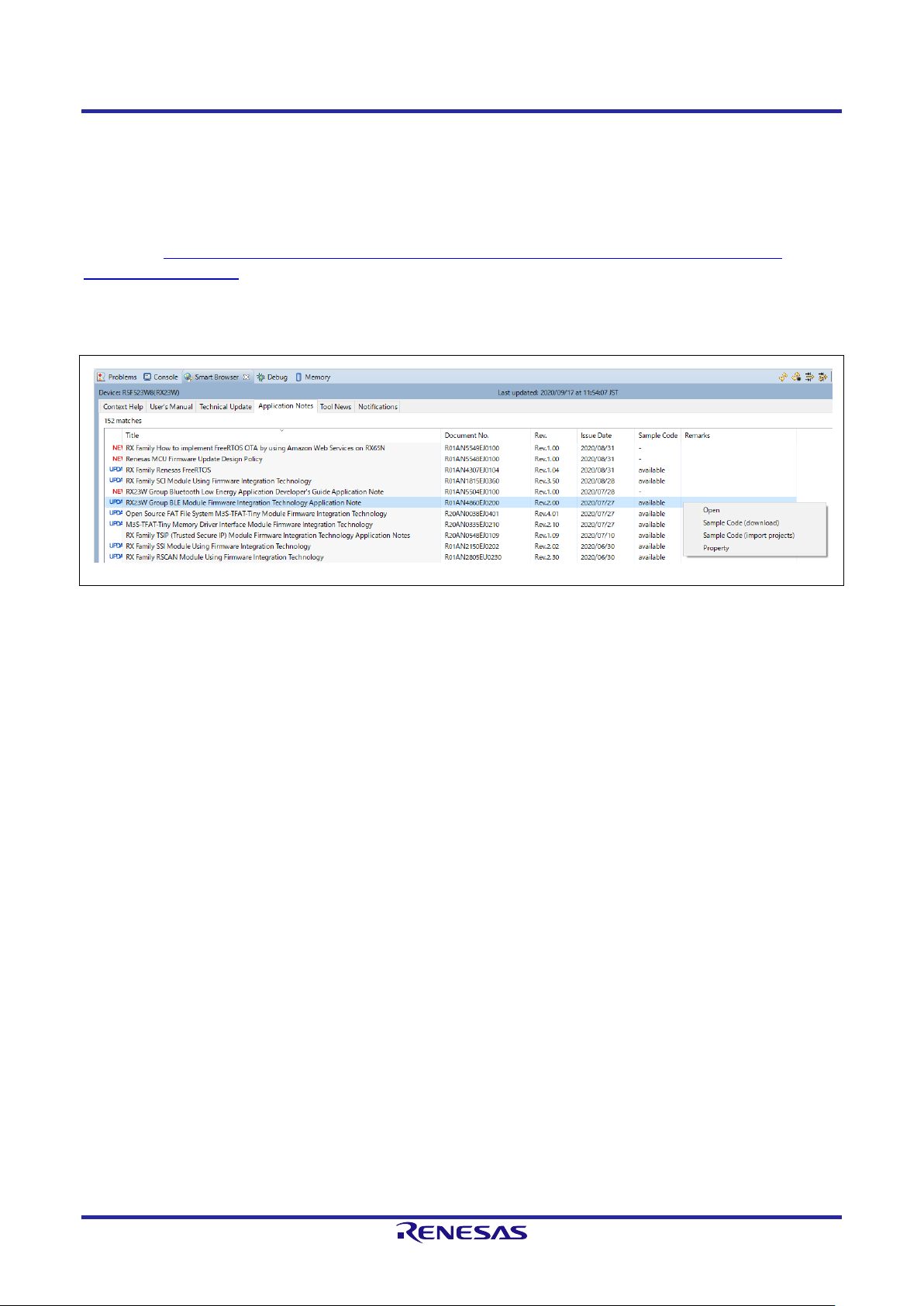
The Bluetooth Low Energy Protocol Stack Basic Package is available from the Renesas RX23W FIT module
Web page (https://www.renesas.com/products/software-tools/software-os-middleware-driver/software-
package/fit-rx23w.html) or “RX23W Group BLE Module Firmware Integration Technology Application Note” on
e2studio Smart Browser. If you want to download only the BLE FIT module, see “2.4 Install”.
Figure 2.1. e2studio Smart Browser
Page 12

Bluetooth Low Energy Protocol Stack Basic Package User's Manual 2. Installation
R01UW0205EJ0103 Rev.1.03 Page 4 of 85
Mar.30.2021
Table 2.1 shows the contents of the Bluetooth Low Energy Protocol Stack Basic Package.
Table 2.1. Contents of the Bluetooth Low Energy Protocol Stack Basic Package
r01an4860xxXXXX-rx23w-ble-fit.zip
XXXX: Revision number
FITDemos\
Sample application folder
ble_demo_rsskrx23w_profile_client.zip
GATT client project for RSSK RX23W
ble_demo_rsskrx23w_profile_server.zip
GATT server project for RSSK RX23W
ble_demo_rsskrx23w_uart_hci.zip
HCI mode project for RSSK RX23W
ble_demo_tbrx23w_FreeRTOS_multi_services.zip
FreeRTOS GATT server project for Target Board for RX23W
ble_demo_tbrx23w_profile_client.zip
GATT client project for Target Board for RX23W
ble_demo_tbrx23w_profile_server.zip
GATT server project for Target Board for RX23W
ble_demo_tbrx23w_uart_hci.zip
HCI mode project for Target Board for RX23W
ble_demo_tbrx23wmodule_profile_client.zip
GATT client project for Target Board for RX23W module
ble_demo_tbrx23wmodule_profile_server.zip
GATT server project for Target Board for RX23W module
ble_demo_tbrx23wmodule_uart_hci.zip
HCI mode project for Target Board for RX23W module
ROM_Files\
Mot files
ble_demo_rsskrx23w_profile_client.mot
GATT client project mot file for RSSK RX23W
ble_demo_rsskrx23w_profile_server.mot
GATT server project mot file for RSSK RX23W
ble_demo_rsskrx23w_uart_hci.mot
HCI mode project mot file for RSSK RX23W
ble_demo_tbrx23w_FreeRTOS_multi_services.mot
FreeRTOS GATT server project mot file for Target Board for RX23W
ble_demo_tbrx23w_profile_client.mot
GATT client project mot file for Target Board for RX23W
ble_demo_tbrx23w_profile_server.mot
GATT server project mot file for Target Board for RX23W
ble_demo_tbrx23w_uart_hci.mot
HCI mode project mot file for Target Board for RX23W
ble_demo_tbrx23wmodule_profile_client.mot
GATT client project mot file for Target Board for RX23W module
ble_demo_tbrx23wmodule_profile_server.mot
GATT server project mot file for Target Board for RX23W module
ble_demo_tbrx23wmodule_uart_hci.mot
HCI mode project mot file for Target Board for RX23W module
FITModules\
FIT module folder
r_ble_rx23w_vX.XX.xml
BLE FIT module xml file
r_ble_rx23w_vX.XX.zip
BLE FIT module body package
r_ble_rx23w_vX.XX_extend.mdf
BLE FIT module mdf file
utilities\
Utility folder
BDAddrWriter.zip
Public BD address writing tool for HCI mode
CLVALTune.zip
Operation tool for calibration for HCI mode
r01an4860ejXXXX-rx23w-ble.pdf
BLE FIT Module Application Note (English)
r01an4860jjXXXX-rx23w-ble.pdf
BLE FIT Module Application Note (Japanese)
r_ble_api_spec.chm
R_BLE API document (English)
Page 13

Bluetooth Low Energy Protocol Stack Basic Package User's Manual 2. Installation
R01UW0205EJ0103 Rev.1.03 Page 5 of 85
Mar.30.2021
2.2 Project Configuration
A BLE Application template project consists of Smart Configurator generation codes extracted from the BLE
FIT module, the BLE QE Utility module and the QE for BLE and other FIT modules. Table 2.2 shows the
project configuration.
Table 2.2. BLE Application template project configuration
[project name]\
Project directory
src\ smc_gen\
A set of source codes generated by Smart Configurator
Config_BLE_PROFILE\
A set of source codes generated by QE for BLE
app_main.c
Framework for user application and profile
gatt_db.c
GATT database
gatt_db.h
r_ble_[profile name]s.c
Profile API
r_ble_[profile name]s.h
r_ble_[profile name]c.c
r_ble_[profile name]c.h
r_ble_rx23w\
BLE FIT module
lib\
BLE Protocol Stack library
ref\
Configuration reference
src\
app_lib\
BLE application auxiliary features
abs\
Abstraction API
board\
LED and Switch Control
cli\
Command line (Input/Output to terminal software)
cmd\
Command line (Command implementation)
discovery\
Profile Common (discovery)
logger\
Logger
profile_cmn\
Profile Common
rtos\
BLE Tack Control
sec_data\
Security Data Management
timer\
Software Timer
platform\
Platform dependent codes
driver\
Data Flash driver for the BLE FIT module
r_ble_pf_config_private.h
BLE configuration control
r_ble_pf_configs.c
r_ble_pf_functions.c
RF driver platform dependent
r_ble_pf_lowpower.c
MCU low power consumption program
r_ble_rx23w_if.h
BLE interface definition file
FIT modules other than the BLE FIT module
[project].c
Application template
Page 14

Bluetooth Low Energy Protocol Stack Basic Package User's Manual 2. Installation
R01UW0205EJ0103 Rev.1.03 Page 6 of 85
Mar.30.2021
2.3 Build Environment
Table 2.3 shows the hardware requirements for building and debugging a BLE Application.
Table 2.3. Hardware requirements
Hardware
Description
Host PC
Windows 10 PC with USB interface.
RX23W Board
Target Board for RX23W [RTK5RX23W0C00000BJ]
Target Board for RX23W module [RTK5RX23W0C01000BJ]
RSSK RX23W [RTK5523W8AC00001BJ]
On-chip debugging emulators
E2 emulator Lite [RTE0T0002LKCE00000R] or
E1 emulator [R0E000010KCE00]
When using the RSSK, either emulator is required.
The Target Board has an on-board debugger equivalent to the E2 emulator Lite, so
there is no need to prepare an emulator.
USB cables
Used to connect to the emulator and RX23W board.
E2 or E1 emulator: 1 USB A-miniB cable
Target Board: 2 USB A-microB cable
RSSK: 1 USB A-microB cable
Table 2.4 shows the software requirements for building and debugging a BLE Application.
Table 2.4. Software requirements
Software
Version
Description
CC-RX
environment
e² studio
v7.8.0 (32bit)
2021_01 (64bit)
Integrated development environment (IDE) for Renesas
devices.
CC-RX compiler
v2.08.00
C/C++ Compiler for RX Family. (download from e2 studio
installer)
Renesas Flash
Programmer
v3.06.00
Tool for programming the on-chip flash memory of Renesas
microcontrollers.
IAR
environment
IAR Embedded
Workbench for Renesas
RX
v4.14.1
Integrated development environment (IDE) for Renesas
devices made by IAR Systems.
Note: Supported by BLE FIT module v1.10 or later.
Page 15

Bluetooth Low Energy Protocol Stack Basic Package User's Manual 2. Installation
R01UW0205EJ0103 Rev.1.03 Page 7 of 85
Mar.30.2021
2.4 Install
2.4.1 BLE FIT Module
This module must be added to each project in which it is used. Renesas recommends using “Smart
Configurator” described in (1) or (3).
(1) Adding the FIT module to your project using “Smart Configurator” in e2 studio.
By using the “Smart Configurator” in e
2
studio, the FIT module is automatically added to your project.
Refer to “Renesas e
2
studio Smart Configurator User Guide (R20AN0451)” for details.
(2) Adding the FIT module to your project using “FIT Configurator” in e2 studio
By using the “FIT Configurator” in e
2
studio, the FIT module is automatically added to your project. Refer
to “Adding Firmware Integration Technology Modules to Projects (R01AN1723)” for details.
(3) Adding the FIT module to your project using “Smart Configurator” on CS+
By using the “Smart Configurator Standalone version” in CS+, the FIT module is automatically added to
your project. Refer to “Renesas e
2
studio Smart Configurator User Guide (R20AN0451)” for details.
(4) Adding the FIT module to your project in CS+
In CS+, please manually add the FIT module to your project. Refer to “Adding Firmware Integration
Technology Modules to CS+ Projects (R01AN1826)” for details.
2.4.2 Demo projects
2.4.2.1 e2 studio Project
Import the demo project zip file under the FITDemos folder to the lowest possible hierarchy.
(e.g. C:\RenesasBLE ) If the folder hierarchy is deep, intermediate files cannot be output when building with e2
studio, and the build may fail.
Also, select a location that does not contain blank character, multi-byte characters, and ampersand character
“&” in the decompression destination path.
Refer to “BLE Module Firmware Integration Technology Application Note (R01AN4860)” for details on
importing the demo project zip file to the e2 studio workspace.
Note: If the demo project import location is not appropriate, the e2 studio build may fail.
2.4.2.2 IAR Embedded Workbench for Renesas RX Project
Unzip the demo project zip file under the “FITDemos” folder and double-click the eww file. Build the project by
[Project]→[Rebuild All] on IAR Embedded Workbench for Renesas RX. After successful build, download the
firmware to the board by selecting [Project]→[Download and Debug].
Page 16
Bluetooth Low Energy Protocol Stack Basic Package User's Manual 3. Software Structure
R01UW0205EJ0103 Rev.1.03 Page 8 of 85
Mar.30.2021
3. Software Structure
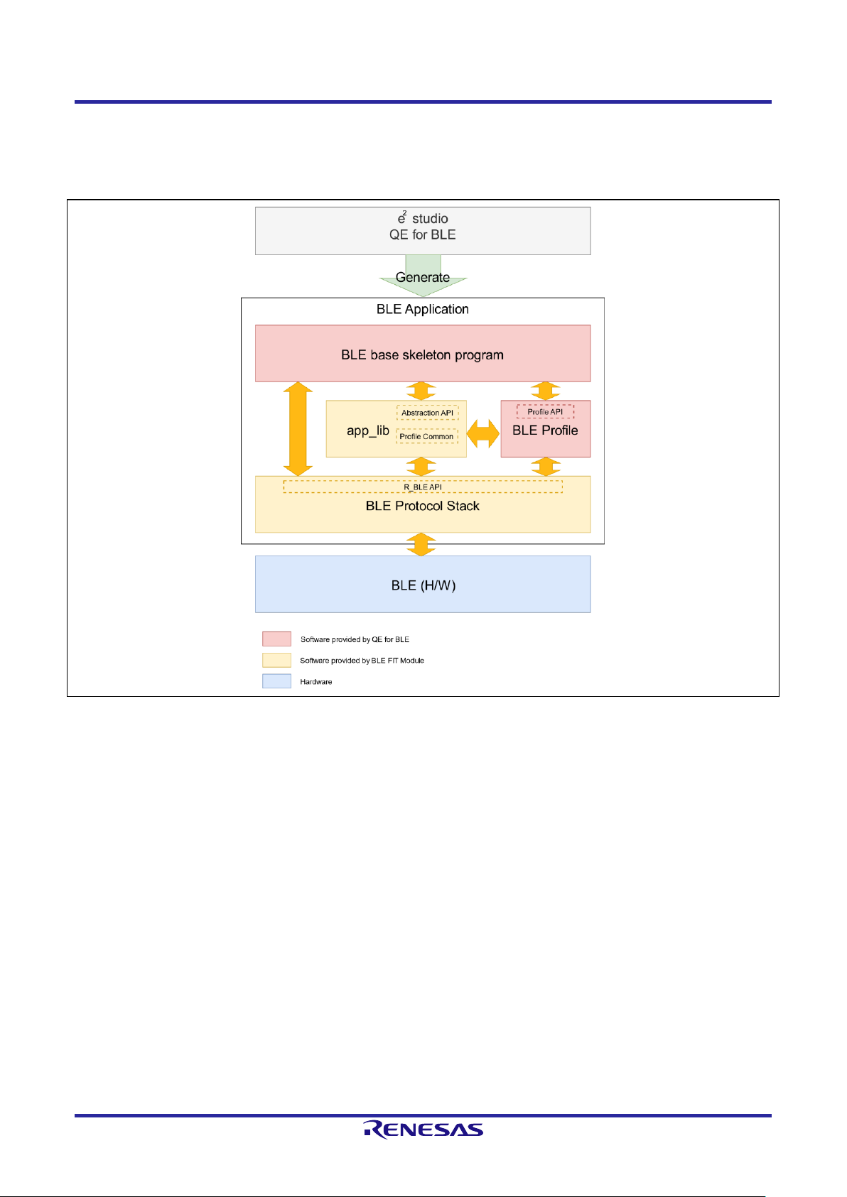
Figure 3.1 shows the BLE Application software structure.
Figure 3.1. BLE Application software structure
The BLE Application consists of BLE Protocol Stack and app_lib provided by the BLE FIT module and
skeleton programs and BLE Profile generated by QE for BLE.
By calling the R_BLE API function provided by the BLE Protocol Stack, the BLE Application can use the BLE
function.
The app_lib provides auxiliary features that can be used by the BLE Application. The BLE communication can
be easily used by using “Abstraction API” that abstracts R_BLE API included in app_lib.
QE for BLE, a solution toolkit that runs on e2 studio, generates skeleton programs for application and profile
development using BLE Protocol Stack and Abstraction API.
Renesas recommends BLE application development using QE for BLE.
For details about how to design a profile with QE for BLE, see “RX23W Group Bluetooth Low Energy Profile
Developer's Guide (R01AN4553)”. For details about how to develop BLE Application, see “RX23W Group
Bluetooth Low Energy Application Developer's Guide (R01AN5504)”.
Page 17
Bluetooth Low Energy Protocol Stack Basic Package User's Manual 3. Software Structure
R01UW0205EJ0103 Rev.1.03 Page 9 of 85
Mar.30.2021
3.1 BLE Protocol Stack
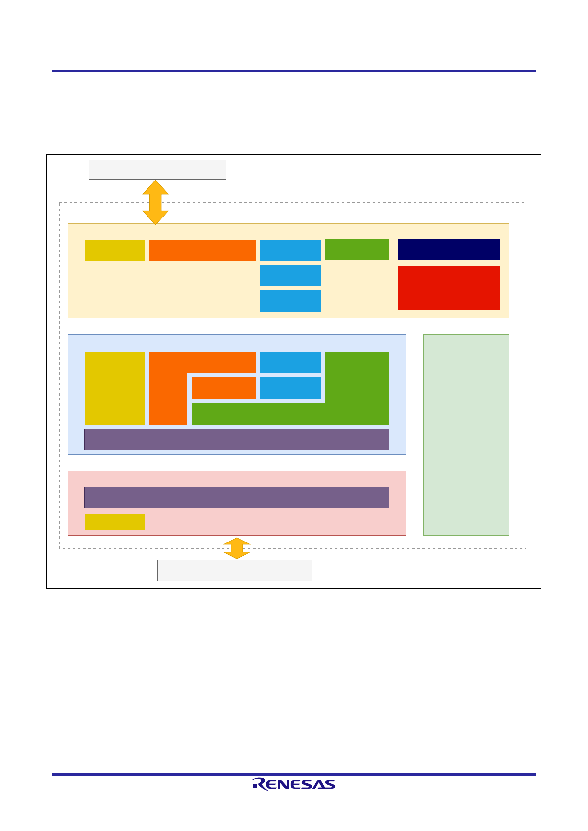
3.1.1 BLE Protocol Stack structure
Figure 3.2 shows the BLE Protocol Stack structure.
BLE Protocol Stack
Host Stack
R_BLE API
L2CAP
Link Layer
GAP
L2CAP
Vendor Specific
MCU Low Power Consumption
Common
HCI
ATTSMP
HCI
Scheduler
Vendor Specific
GAP GATT
GATT Client
GATT Server
GATT Common
BLE (H/W)
BLE Application Layer
Vendor Specific
Figure 3.2. BLE Protocol Stack structure
BLE Protocol Stack consists of R_BLE API, Host Stack, Link Layer, and Scheduler.
Page 18

Bluetooth Low Energy Protocol Stack Basic Package User's Manual 3. Software Structure
R01UW0205EJ0103 Rev.1.03 Page 10 of 85
Mar.30.2021
• R_BLE API
The R_BLE API provides the APIs shown in Table 3.1 to provide BLE functions for BLE applications. Refer to
“R_BLE API document (r_ble_api_spec.chm)” for detailed specifications of each API.
Table 3.1. R_BLE API overview
R_BLE_API
Protocol/Profile
Description
Common API
⎯
API for control BLE Open / Close and scheduler processing.
Main features
• Open/Close the BLE protocol stack.
• Execute the BLE task.
• Add an event in the BLE protocol stack internal queue.
GAP API
GAP
SMP
API for supports procedures defined in GAP and SMP.
Main features
• GAP
Advertising, Scan, Connection, Security
• SMP
Pairing
GATT Server API
ATT
GATT
API for GATT Server that publishes service-related attributes and data
sets (GATT Database).
Main features
• Access to GATT Database
• Notification / Indication
GATT Client API
ATT
GATT
API for GATT Client that makes requests to GATT Server.
Main features
• Service/Characteristic Discovery
• Characteristic Read/Write
GATT Common API
ATT
GATT
API for functions used in common with GATT Server/Client.
L2CAP API
L2CAP
API for data transfer on channels that perform credit-based flow
control.
Vendor Specific API
⎯
API that provides Renesas original extended features.
Main features
• Enhanced Direct Test Mode
• Set/Get BD Address
MCU Low Power
Consumption API
⎯
API for reducing MCU power consumption.
The supported API differs depending on the type of BLE Protocol Stack. See Table 3.4 for the APIs supported
by each library.
Page 19
Bluetooth Low Energy Protocol Stack Basic Package User's Manual 3. Software Structure
R01UW0205EJ0103 Rev.1.03 Page 11 of 85
Mar.30.2021
• Host Stack
Host Stack provides the protocol and profile functions specified by Bluetooth SIG. The data received from the
R_BLE API is sent to the Link Layer according to the procedures specified in each protocol and profile, and
the data received from the Link Layer is notified as an R_BLE API event or data.
• Link Layer
The Link Layer controls the BLE hardware implemented in the MCU and provides BLE functions such as
Advertising, Scan, Connection, and Data Communication to the Host Stack via HCI (Host Controller Interface).
BLE commands and transmission data are sent from Host Stack to Link Layer. BLE command results and
data received from remote devices are sent from Link Layer to Host Stack.
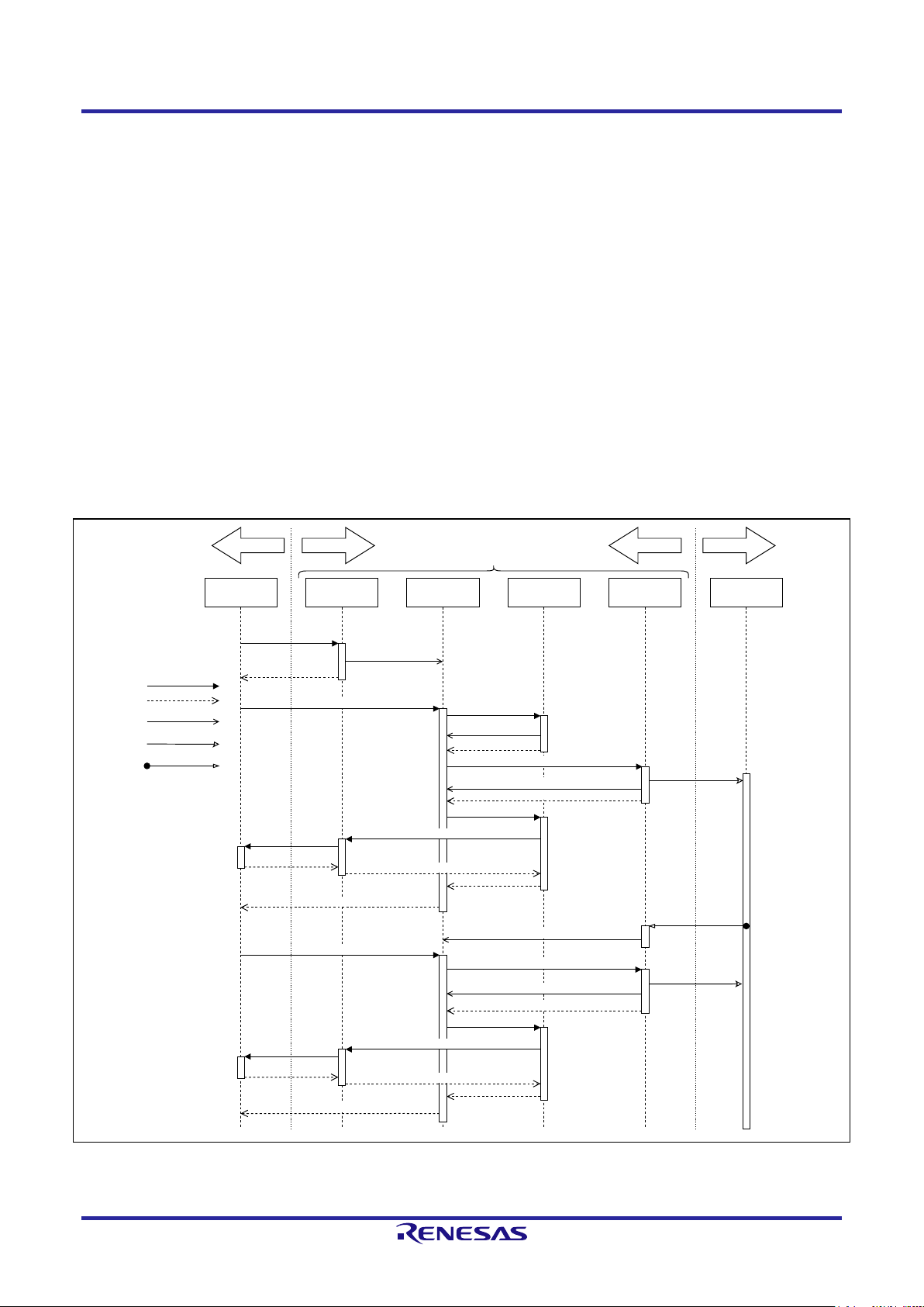
• Scheduler
Scheduler processes the task according to the message queue sent to the task of each layer of BLE Protocol
Stack by R_BLE_Execute() of Common API. Figure 3.3 shows the basic sequence chart of BLE Protocol
Stack.
R_BLE API Scheduler Host Stack Link Layer(LL) BLE H/WApplication
Call R_BLE API
return R_BLE API
Send Message to
Host Stack
Call R_BLE_Execute()
return R_BLE_Execute()
Execute Task
return
Send Message to LL
Execute Task
return
Access BLE H/W
Send Message to Host Stack
BLE Interrupt
Execute Task
return
return
callback
R_BLE event callback
return
Send Message to LL
Call R_BLE_Execute()
return R_BLE_Execute()
Execute Task
return
Access BLE H/W
Send Message to Host Stack
Execute Task
return
callback
return
R_BLE event callback
return
Function Call
Send Message
return
BLE Interrupt
Access BLE H/W
Software HardwareSource Code Library
BLE Protcol Stack
Figure 3.3. Basic sequence chart of BLE Protocol Stack
Page 20

Bluetooth Low Energy Protocol Stack Basic Package User's Manual 3. Software Structure
R01UW0205EJ0103 Rev.1.03 Page 12 of 85
Mar.30.2021
3.1.2 BLE Protocol Stack library
The BLE FIT module provides the following three types of BLE Protocol Stack as a static library according to
the supported BLE features. By selecting the type according to the feature used in the BLE Application, it is
possible to reduce the ROM/RAM code size of the program.
Refer to “BLE Module Firmware Integration Technology (R01AN4860) 2.10 Code Size” for the code size of
each type.
Table 3.2. BLE Protocol Stack library
Library Type
Library File Name
Description
All features
lib_ble_ps_ccrx_a.lib
All features supported by BLE Protocol Stack can be used.
Balance
lib_ble_ps_ccrx_b.lib
LE Advertising Extensions with large ROM/RAM size usage is
disabled. However, LE 2M PHY and LE Coded PHY can be
changed after connection.
Compact
lib_ble_ps_ccrx_c.lib
Dedicated to BLE slave operation, it can be used in applications
that do not require master operation, such as sensor devices.
Table 3.3 shows the BLE features supported by each type of BLE Protocol Stack.
Table 3.3. Features supported by each type of BLE Protocol Stack
BLE Features
Library Type
All features
Balance
Compact
LE 2M PHY
Yes
Yes
No
LE Coded PHY
Yes
Yes
No
LE Advertising Extensions
Yes
No
No
LE Channel Selection Algorithm #2
Yes
Yes
No
High Duty Cycle Non-Connectable Advertising
Yes
Yes
Yes
LE Secure Connections
Yes
Yes
Yes
Link Layer privacy
Yes
Yes
Yes
Link Layer Extended Scanner Filter policies
Yes
Yes
No
LE Data Packet Length Extension
Yes
Yes
Yes
LE L2CAP Connection Oriented Channel Support
Yes
No
No
Low Duty Cycle Directed Advertising
Yes
Yes
Yes
LE Link Layer Topology
Yes
Yes
No
LE Ping
Yes
Yes
Yes
GAP Role
Central
Peripheral
Observer
Broadcaster
Central
Peripheral
Observer
Broadcaster
Peripheral
Broadcaster
GATT Role
Sever
Client
Sever
Client
Sever
Client
32-bit UUID Support in LE
Yes
Yes
Yes
Page 21

Bluetooth Low Energy Protocol Stack Basic Package User's Manual 3. Software Structure
R01UW0205EJ0103 Rev.1.03 Page 13 of 85
Mar.30.2021
• LE 2M PHY
Supports BLE communication with 2Msym/s PHY.
• LE Coded PHY
Supports BLE communication with Coded PHY.
Communication over a long range than 1M PHY and 2M PHY is possible.
• LE Advertising Extensions
An extension of Advertising. The features are as follows.
⎯ Up to 4 independent advertising can be executed simultaneously.
(Use the configuration option BLE_CFG_RF_ADV_SET_MAX to set the number of Advertising
executed simultaneously.)
⎯ Expansion of Advertising Data / Scan Response Data size up to 1650 bytes.
(Set the maximum size (bytes) with the configuration option BLE_CFG_RF_ADV_DATA_MAX.)
⎯ Periodic Advertising is possible.
• LE Channel Selection Algorithm # 2
This feature selects a channel using the algorithm for selecting a hopping channel added in Version 5.0.
• High Duty Cycle Non-Connectable Advertising
This feature supports non-connectable advertising with a minimum interval of 20 msec.
• LE Secure Connections
Elliptic curve Diffie-Hellman key agreement method (ECDH) supports passive eavesdropping pairing.
• Link Layer privacy
This feature avoids tracking from other BLE devices by changing the BD Address periodically.
• LE Data Packet Length Extension
This feature expands the BLE data communication packet size.
It can be expanded to 251 bytes.
• LE L2CAP Connection Oriented Channel Support
This feature supports communication using the L2CAP credit based flow control channel.
• Low Duty Cycle Directed Advertising
This feature supports low duty cycle advertising for reconnection with known devices.
• LE Link Layer Topology
This feature supports both Master and Slave roles and can operate as Master when connected to a remote
device and as Slave when connected to another remote device.
Page 22

Bluetooth Low Energy Protocol Stack Basic Package User's Manual 3. Software Structure
R01UW0205EJ0103 Rev.1.03 Page 14 of 85
Mar.30.2021
• LE Ping
After connection encryption, this feature checks whether connection is maintained by a packet
transmission request including MIC field.
• GAP Role
GAP Role supports the following.
⎯ Central: A device that sends a connection request to a peripheral device.
⎯ Peripheral: A device that accepts connection requests from Central and establishes a connection.
⎯ Observer: A device that scans Advertising.
⎯ Broadcaster: A device that sends Advertising.
• GATT Role
GATT Role supports the following.
⎯ Server: A device that prepares Characteristic provided by service in GATT Database and responds to requests
from Client.
⎯ Client: A device that makes request for services provided by Server.
• 32-bit UUID Support in LE
Supports GATT 32-bit UUID.
Table 3.4 shows R_BLE API support for each BLE Protocol Stack library.
Table 3.4. R_BLE API support for BLE Protocol Stack library
R_BLE_API
Library Type
All features
Balance
Compact
Common API
Yes
Yes
Yes
GAP API
Yes
C.1
C.1
GATT Common API
Yes
Yes
Yes
GATT Server API
Yes
Yes
Yes
GATT Client API
Yes
Yes
Yes
L2CAP API
Yes
No
No
Vendor Specific API
Yes
Yes
Yes
MCU Low Power Consumption API
Yes
Yes
Yes
C.1: Support for each GAP API varies depending on the type of BLE Protocol Stack library.
Refer to “R_BLE API document (r_ble_api_spec.chm)” for details.
The BLE Protocol Stack type is determined by the BLE_CFG_LIB_TYPE definition value in the configuration
file (r_ble_rx23w_config.h). Determine which type is used by BLE_CFG_LIB_TYPE at the time of build,
rename lib_ble_ps_ccrx_x.lib (x: a or b or c) to lib_ble_ps_ccrx.lib and link.
Page 23
Bluetooth Low Energy Protocol Stack Basic Package User's Manual 3. Software Structure
R01UW0205EJ0103 Rev.1.03 Page 15 of 85
Mar.30.2021
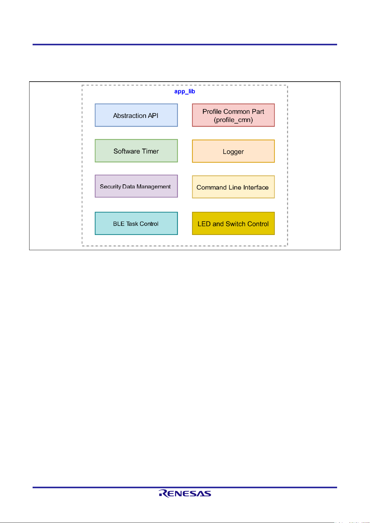
3.2 app_lib
Figure 3.4 shows the app_lib structure. Details of each are explained in “5 Original Features”.
Figure 3.4. app_lib structure
The functions provided by app_lib are described below.
3.2.1 Abstraction API
Abstraction API is an API that makes it easy to use frequently used functions in BLE Protocol Stack. Refer to
“R_BLE API document (r_ble_api_spec.chm)” for detailed specifications of Abstraction API.
3.2.2 Software Timer
The software timer uses Compare Match Timer (CMT).
When using this function, add CMT FIT module to the application. The CMT channel to be used is dynamically
allocated by FIT. Refer to “RX23W Group Bluetooth Low Energy Application Developer’s Guide (R01AN5504)
4.1 Software Timer” for details.
3.2.3 Security Data Management
Provides an interface for automatically saving bonding information to Data Flash when pairing is successful.
When using this feature, set BLE_CFG_EN_SEC_DATA to “1” from the BLE FIT module component settings.
About the use of security data management, see “RX23W Group Bluetooth Low Energy Application
Developer’s Guide (R01AN5504) 4.4 Security Data Management”. About data configuration of security data
management, see “5.2 Security Data Management ”.
Page 24

Bluetooth Low Energy Protocol Stack Basic Package User's Manual 3. Software Structure
R01UW0205EJ0103 Rev.1.03 Page 16 of 85
Mar.30.2021
3.2.4 Profile Common
The Profile Common is common functions to BLE Profile. It is called from the profile source code generated by
QE for BLE.
3.2.5 Logger
Outputs a log message. The output level is set by the configuration option BLE_CFG_LOG_LEVEL. Refer to
“RX23W Group Bluetooth Low Energy Application Developer’s Guide (R01AN5504) 4.3 Logger” for details.
3.2.6 Command line
The command line feature uses the BLE functions via a command input from serial. It uses Serial
Communication Interface (SCI). Command types are standard commands provided by the BLE FIT module
and user commands created by user. For details of standard commands and user commands, see the
documents in Table 3.5.
Table 3.5.Command line reference documents
Command
Reference
Standard
Specification
“5.1 Command Line Interface”
Usage
“RX23W Group Bluetooth Low Energy Application Developer’s Guide (R01AN5504)
4.2.1 How to use the standard command”
User
Creation
Method
“RX23W Group Bluetooth Low Energy Application Developer’s Guide (R01AN5504)
4.2.2 How to create a user command”
3.2.7 LED and Switch Control
The LED and Switch Control feature controls LEDs and switches on board. About setting the BLE FIT and the
IRQ FIT configuration options to use this feature, see “RX23W Group BLE Module Firmware Integration
Technology (R01AN4860) 4.5.4 LED and Switch Control”. About how to use this feature, see “RX23W Group
Bluetooth Low Energy Application Developer’s Guide (R01AN5504) 4.5 Board and LED switch”.
3.2.8 BLE Task Control
The BLE Task Control feature is enabled if a project including the BLE FIT module has “FreeRTOS” as RTOS.
Another task wakes the BLE task up by this feature. About how to use it, see “RX23W Group BLE Module
Firmware Integration Technology (R01AN4860) 6.4 Wake up BLE task from another task”.
Page 25

Bluetooth Low Energy Protocol Stack Basic Package User's Manual 4. Software Setting
R01UW0205EJ0103 Rev.1.03 Page 17 of 85
Mar.30.2021
4. Software Setting
User can configure the BLE Application according to the purpose with the BLE FIT module.
4.1 Configuration options
Table 4.1 shows configuration options of the BLE FIT module. Configuration option settings are determined by
the macro definition in r_ble_rx23w_config.h. When using Smart Configurator, configuration options can be
set on the software component setting screen. The setting value is automatically reflected in
r_ble_rx23w_config.h when adding a module.
Table 4.1. List of configuration options (1/8)
Configuration Options
Description
BLE_CFG_LIB_TYPE
Default : "0"
Type of the BLE Protocol Stack. Select one of the followings.
0: All features
1: Balance
2: Compact
Refer to “3.1.2 BLE Protocol Stack” for details.
BLE_CFG_RF_DBG_PUB_ADDR
Default : "{0xFF,0xFF,0xFF,0x50,0x90,0x74}"
Initial Public Address. If the public addresses in the Code Flash and the
Data Flash are all 0x00 or 0xFF, the device adopts this public address.
If all 0x00 or 0xFF is set, the device uses ‘74:90:50:FF:FF:FF’ as public
address.
BLE_CFG_RF_DBG_RAND_ADDR
Default : “{0xFF,0xFF,0xFF,0xFF,0xFF,0xFF}"
Initial Static Address. If the static addresses in the Code Flash and the
Data Flash are all 0x00 or 0xFF, the device adopts this static address. If
all 0x00 or 0xFF is set, the device uses the value generated with the
device specific value the static address.
BLE_CFG_RF_CONN_MAX
Default : "7"
Maximum number of simultaneous connections.
Range : 1 to 7
BLE_CFG_RF_CONN_DATA_MAX
Default : "251"
Maximum packet data length (bytes).
Range : 27 to 251
BLE_CFG_RF_ADV_DATA_MAX
Default : "1650"
Maximum advertising data length (bytes).
Range : 31 to 1650
The maximum advertising data length of the BLE Protocol Stack
libraries other than "All features" is fixed to 31bytes.
BLE_CFG_RF_ADV_SET_MAX
Default : "4"
Maximum number of the advertising set.
Range : 1 to 4
The number of the advertising set of the BLE Protocol Stack libraries
other than "All features" is fixed to one.
BLE_CFG_RF_SYNC_SET_MAX
Default : "2"
Maximum number of periodic sync set.
Range : 1 to 2
If the BLE Protocol Stack library is other than "All features", this option is
not used.
Page 26

Bluetooth Low Energy Protocol Stack Basic Package User's Manual 4. Software Setting
R01UW0205EJ0103 Rev.1.03 Page 18 of 85
Mar.30.2021
Table 4.1. List of configuration options (2/8)
Configuration Options
Description
BLE_CFG_EVENT_NOTIFY_CONN_START
Default : "0"
Enable or disable start interrupt notification of a connection complete
event.
0: Disable
1: Enable
Because the start notification is triggered by the interrupt, it occurs after
the actual RF event.
BLE_CFG_EVENT_NOTIFY_CONN_CLOSE
Default : "0"
Enable or disable end interrupt notification of a connection complete
event.
0: Disable
1: Enable
If the connection is terminated by a command, the notification doesn't
occur.
BLE_CFG_EVENT_NOTIFY_ADV_START
Default : "0"
Enable or disable the advertising event start interrupt notification.
0: Disable
1: Enable
The notification occurs at the following timings.
• Start Primary Advertising channel.
• Start Secondary Advertising Channel
• Start Periodic Advertising. (When the Extended Advertising is
enabled.)
Because the start notification is triggered by the interrupt, it occurs after
the actual RF event.
BLE_CFG_EVENT_NOTIFY_ADV_CLOSE
Default : "0"
Enable or disable the advertising event complete interrupt notification.
0: Disable
1: Enable
The notification occurs at the following timings.
• Complete Primary Advertising channel.
• Complete Secondary Advertising Channel
• Complete Periodic Advertising.(When the Extended Advertising is
enabled.)
If the advertising is terminated by a command, the notification doesn't
occur.
Page 27

Bluetooth Low Energy Protocol Stack Basic Package User's Manual 4. Software Setting
R01UW0205EJ0103 Rev.1.03 Page 19 of 85
Mar.30.2021
Table 4.1. List of configuration options (3/8)
Configuration Options
Description
BLE_CFG_EVENT_NOTIFY_SCAN_START
Default : "0"
Enable or disable the scan start interrupt notification.
0: Disable
1: Enable
If the scan interval is equal to the scan window, this notification doesn't
occur.
Because the start notification is triggered by the interrupt, it occurs after
the actual RF event.
BLE_CFG_EVENT_NOTIFY_SCAN_CLOSE
Default : "0"
Enable or disable the scan complete interrupt notification
0: Disable
1: Enable
If the scan interval is equal to the scan window, this notification doesn't
occur.
If the scan is terminated by a command, the notification doesn't occur.
BLE_CFG_EVENT_NOTIFY_INIT_START
Default : "0"
Enable or disable the notification that the scan start interrupt has
occurred in sending a connection request.
0: Disable
1: Enable
If the scan interval is equal to the scan window, this notification doesn't
occur.
Because the start notification is triggered by the interrupt, it occurs after
the actual RF event.
BLE_CFG_EVENT_NOTIFY_INIT_CLOSE
Default : "0"
Enable or disable the notification that the scan complete interrupt has
occurred in sending a connection request.
0: Disable
1: Enable
If the scan interval is equal to the scan window, this notification doesn't
occur.
If the connection request is terminated by a command, the notification
doesn't occur.
BLE_CFG_EVENT_NOTIFY_DS_START
Default : "0"
Enable or disable the RF_DEEP_SLEEP start notification.
0: Disable
1: Enable
BLE_CFG_EVENT_NOTIFY_DS_WAKEUP
Default : "0"
Enable or disable the RF_DEEP_SLEEP wakeup notification.
0: Disable
1: Enable
Page 28

Bluetooth Low Energy Protocol Stack Basic Package User's Manual 4. Software Setting
R01UW0205EJ0103 Rev.1.03 Page 20 of 85
Mar.30.2021
Table 4.1. List of configuration options (4/8)
Configuration Options
Description
BLE_CFG_RF_CLVAL
Default : "6"
Adjustment value of the 32MHz crystal oscillator for RF part.
Set this option according to the board environment.
Range : 0 to 15
Refer to"RX23W Group Tuning procedure of Bluetooth dedicated clock
frequency(R01AN4762)" for details.
If you select R5F523W8CxLN or R5F523W8DxLN, set “7”.
BLE_CFG_RF_DDC_EN
Default : "0"
Enable or disable the DC-DC on the RF.
0: Disable
1: Enable
If you use Target Board, set “0”.
BLE_CFG_RF_EXT32K_EN
Default : "0"
Slow clock source to the RF.
0: RF_LOCO
1: External 32.768kHz
If this option is set to 1, the sub clock is required to be enabled in the
Smart Configurator clock configuration.
BLE_CFG_RF_MCU_CLKOUT_PORT
Default : "0"
Port of the MCU CLKOUT.
0: PE3
1: PE4
If BLE_CFG_RF_EXT32K_EN option is 0, this option is ignored.
BLE_CFG_RF_MCU_CLKOUT_FREQ
Default : "0"
Output frequency from the MCU CLKOUT.
0: MCU CLKOUT frequency 32.768kHz
1: MCU CLKOUT frequency 16.384kHz
If BLE_CFG_RF_EXT32K_EN option is 0, this option is ignored.
BLE_CFG_RF_SCA
Default : "250"
Sleep Clock Accuracy(SCA) for the RF slow clock.
Range : 0 to 500
If BLE_CFG_RF_EXT32K_EN option is 0, the SCA is fixed to more than
250 [ppm] and this option is ignored.
BLE_CFG_RF_MAX_TX_POW
Default : "1"
Maximum transmit power configuration.
0: max +0dBm
1: max +4dBm
Page 29

Bluetooth Low Energy Protocol Stack Basic Package User's Manual 4. Software Setting
R01UW0205EJ0103 Rev.1.03 Page 21 of 85
Mar.30.2021
Table 4.1. List of configuration options (5/8)
Configuration Options
Description
BLE_CFG_RF_DEF_TX_POW
Default : "0"
Default transmit power level.
Range : 0 to 2
This option depends on BLE_CFG_RF_MAX_TX_POW option.
If the BLE_CFG_RF_MAX_TX_POW option is 0 (0dBm),
BLE_CFG_RF_DEF_TX_POW is as follows.
0 (High) : 0 dBm
1 (Mid) : 0 dBm
2 (Low) : -18 dBm
If the BLE_CFG_RF_MAX_TX_POW option is 1 (+4dBm),
BLE_CFG_RF_DEF_TX_POW is as follows.
0 (High) : +4 dBm
1 (Mid) : 0 dBm
2 (Low) : -20 dBm
BLE_CFG_RF_CLKOUT_EN
Default : "0"
CLKOUT_RF output.
Select one of the followings.
0: No output
5: 4MHz output
6: 2MHz output
7: 1MHz output
BLE_CFG_RF_DEEP_SLEEP_EN
Default : "1"
Enable or disable the RF Deep Sleep.
0: Disable
1: Enable
BLE_CFG_MCU_MAIN_CLK_KHZ
Default : "4000"
MCU main clock frequency (kHz).
This option needs to be configured according to the board environment.
If the HOCO is used, this option is ignored.
If the Main Clock is used, set a value within the range between 1000
and 20000.
If the PLL Circuit is used, set a value within the range between 4000
and 12500.
Set the clock frequency configured in the Smart Configurator clock
configuration.
BLE_CFG_DEV_DATA_CF_BLOCK
Default : "16"
The Code Flash(ROM) block stored the device specific data.
Range : -1 to 255
If this option is set to “-1”, the device specific data in the Code Flash is
not used.
The blocks from "0" to "15" are the Start-Up Program Protection block.
If the Start-Up Program Protection is used, don’t use the blocks from "0"
to "15".
Page 30

Bluetooth Low Energy Protocol Stack Basic Package User's Manual 4. Software Setting
R01UW0205EJ0103 Rev.1.03 Page 22 of 85
Mar.30.2021
Table 4.1. List of configuration options (6/8)
Configuration Options
Description
BLE_CFG_DEV_DATA_DF_BLOCK
Default : "-1"
The E2 Data Flash block stored the device specific data.
Range : -1 to 7
If this option is set to “-1”, the device specific data in the E2 DataFlash is
not used.
Specify a block number different from the block number specified by
BLE_CFG_SECD_DATA_DF_BLOCK.
BLE_CFG_GATT_MTU_SIZE
Default : "247"
The MTU size (bytes) for the GATT communication.
Range : 23 to 247
BLE_CFG_NUM_BOND
Default : "7"
Maximum number of the bonding information stored in the Data Flash.
Range : 1 to 7
BLE_CFG_EN_SEC_DATA
Default : "0"
Enable or disable the security data management.
The bonding information is stored in the Data Flash block specified by
BLE_CFG_SECD_DATA_DF_BLOCK by this option.
0: Disable
1: Enable
If this option is enabled, add the Data Flash FIT module.
BLE_CFG_SECD_DATA_DF_BLOCK
Default : "0"
The Data Flash block for the security data management to store the
bonding information.
Range : 0 to 7
Specify a block number different from the block number specified by
BLE_CFG_DEV_DATA_DF_BLOCK.
BLE_CFG_CMD_LINE_EN
Default : "0"
Enable or disable the command line function.
0: Disable
1: Enable
If this option is enabled, add the SCI FIT module.
Page 31

Bluetooth Low Energy Protocol Stack Basic Package User's Manual 4. Software Setting
R01UW0205EJ0103 Rev.1.03 Page 23 of 85
Mar.30.2021
Table 4.1. List of configuration options (7/8)
Configuration Options
Description
BLE_CFG_CMD_LINE_CH
Default : "1"
SCI Channel for the command line function.
Set one of the following values:
1: SCI1
5: SCI5
8: SCI8
12: SCI12 (BGA 85pin only)
Enable the SCI channel for the command line in the SCI FIT module
configuration.
If the BLE_CFG_CMD_LINE_EN is 0, this option is ignored.
The SCI used in the HCI mode must be set in "6.3.1 Configuration
Options of UART Driver" instead of this macro.
BLE_CFG_BOARD_LED_SW_EN
Default : "0"
Enable or disable support the board LED & Switch control.
0: Disable
1: Enable
If the option is enabled, add the IRQ FIT module and the GPIO FIT
module.
BLE_CFG_BOARD_TYPE
Default : "0"
Board type.
Range : 0 to 3
0 : Customer board
1 : Target Board
2 : RSSK
3: Evaluation board
BLE_CFG_LOG_LEVEL
Default : "3"
Log level.
Range : 0 to 3
0 : disable
1 : Error
2 : Error & Warning
3 : Error & Warning & Debug
Page 32

Bluetooth Low Energy Protocol Stack Basic Package User's Manual 4. Software Setting
R01UW0205EJ0103 Rev.1.03 Page 24 of 85
Mar.30.2021
Table 4.1. List of configuration options (8/8)
Configuration Options
Description
BLE_CFG_ABS_API_EN
Default : “1”
Set enable/disable of the Abstraction API.
0: Disable
1: Enable
BLE_CFG_SOFT_TIMER_EN
Default : “1”
Set enable/disable of the software timer provided by app_lib.
0: Disable
1: Enable
To use the Abstraction API, enable this option.
BLE_CFG_MCU_LPC_EN
Default : “1”
Set enable/disable the low power consumption function of the MCU.
0: Disable
1: Enable
BLE_CFG_HCI_MODE_EN
Default : “0”
Set startup in HCI mode.
0: Startup in normal mode
1: Startup in HCI mode
Page 33

Bluetooth Low Energy Protocol Stack Basic Package User's Manual 4. Software Setting
R01UW0205EJ0103 Rev.1.03 Page 25 of 85
Mar.30.2021
4.2 Sections
The BLE Protocol Stack library provides a mechanism for Device Firmware Update (DFU) by Over The Air
(OTA) using BLE communication. In order to specify the section allocation of the BLE Protocol Stack library,
the section name different from the standard section name shown in Table 4.2 is added to the code of the BLE
Protocol Stack library ("BLE_" is added to the beginning of the standard section name) Specified name).
Table 4.2. Section name of BLE Protocol Stack library
#
Name
BLE Protocol Stack Section Name
1
Program area
BLE_P
2
Constant area
BLE_C
BLE_C_2
BLE_C_1
3
Initialized data area (ROM)
BLE_D
BLE_D_2
BLE_D_1
4
Initialized data area (RAM)
BLE_R
BLE_R_2
BLE_R_1
5
Uninitialized data area
BLE_B
BLE_B_2
BLE_B_1
6
switch statement branch table area
BLE_W
BLE_W_2
BLE_W_1
7
Literal area
BLE_L
The section name of the BLE Protocol Stack library must be set as described in “4.2.1 Linker settings for
application project”.
Since the BLE section is initialized by the R_BLE_Open() API that performs BLE initialization, there is no need
to change the program code in the DTBL/BTBL table.
Page 34

Bluetooth Low Energy Protocol Stack Basic Package User's Manual 4. Software Setting
R01UW0205EJ0103 Rev.1.03 Page 26 of 85
Mar.30.2021
4.2.1 Linker settings for application project
Add the section name of the BLE Protocol Stack library shown in Table 4.2 in the application section allocation
settings. In CC-RX compiler, the wildcard character “*” can be specified for the section name.
The section layout of the e2 studio project is set in [Section] of [Linker].
Figure 4.1. e2 studio project section layout
Table 4.3 shows the section allocation settings when OTA is not used. Wildcards are used so that the section
specification is not complicated.
Page 35

Bluetooth Low Energy Protocol Stack Basic Package User's Manual 4. Software Setting
R01UW0205EJ0103 Rev.1.03 Page 27 of 85
Mar.30.2021
Table 4.3. Section layout of BLE library section (when OTA is not used)
Address
Section Name
0x00000004
(RAM)
SU
SI
B_1
R_1
B_2
R_2 B R
BLE_B*
BLE_R*
0xFFF80000
(ROM)
PResetPRG
C_1
C_2 C C$*
D*
W* L PIntPRG
P
BLE_C*
BLE_D*
BLE_W*
BLE_L
BLE_P
0xFFFFFF80
EXCEPTVECT
0xFFFFFFFC
RESETVECT
Also, add the BLE Protocol Stack library section in Table 4.2 to the section that mapped from ROM to RAM.
This setting does not allow the use of wildcards. You only need to add sections that have assignments.
In e2 studio, set [Linker] → [Section] → [Symbol file] → [ROM to RAM mapped section].
Page 36

Bluetooth Low Energy Protocol Stack Basic Package User's Manual 4. Software Setting
R01UW0205EJ0103 Rev.1.03 Page 28 of 85
Mar.30.2021
Figure 4.2. Setting “ROM to RAM mapped section” in e2 studio project
Add the BLE_D/BLE_R section of the BLE library as shown below.
D=R
D_1=R_1
D_2=R_2
BLE_D=BLE_R
BLE_D_1=BLE_R_1
BLE_D_2=BLE_R_2
Note: If there is no assignment to the corresponding section, a link error will occur. The “BLE_D_8” section is not used in
the BLE Protocol Stack library.
Page 37

Bluetooth Low Energy Protocol Stack Basic Package User's Manual 4. Software Setting
R01UW0205EJ0103 Rev.1.03 Page 29 of 85
Mar.30.2021
4.3 Bluetooth Device Address
Refer to "5.4 Device-specific Data Management" for Bluetooth Device Address used in BLE Protocol Stack.
4.4 Bluetooth Device Name
The following settings are required for Bluetooth Device Name depending on the inform method.
4.4.1 Inform by Advertising packet
Using the API shown in Table 4.4, it is possible to start advertising including the Bluetooth Device Name in
Advertising Data or Scan Response Data, and to inform Bluetooth Device Name to the Scanner device.
Table 4.4. API to set Advertising Data
R_BLE_API
Parameter structure
Member name for setting
Advertising Data or
Scan Response Data
R_BLE_GAP_SetAdvSresData()
st_ble_gap_adv_data_t
p_data
R_BLE_ABS_StartLegacyAdv()
st_ble_abs_legacy_adv_param_t
p_adv_data
p_sres_data
R_BLE_ABS_StartExtAdv()
st_ble_abs_ext_adv_param_t
p_adv_data
R_BLE_ABS_StartNonConnAdv()
st_ble_abs_non_conn_adv_param_t
p_adv_data
Set the data in the format shown in Figure 4.3 to Advertising Data or Scan Response Data.
LSB MSB
Length AD Type Device Name
Figure 4.3. Bluetooth Device Name format in Advertising packet
Table 4.5 describes the fields in the Bluetooth device name format.
Table 4.5. Bluetooth Device Name field
Field
Description
Length
The total number of bytes for “Device Name” and “AD Type”.
AD Type *1
(Advertising Data Type)
Indicates the type to be inform in the “Device Name” field.
0x08: «Shortened Local Name»
0x09: «Complete Local Name»
Device Name
Bluetooth Device Name string.
*1: For other AD types, refer to Bluetooth SIG, “Assigned numbers and GAP”.
Page 38

Bluetooth Low Energy Protocol Stack Basic Package User's Manual 4. Software Setting
R01UW0205EJ0103 Rev.1.03 Page 30 of 85
Mar.30.2021
Figure 4.4 shows an example of setting Bluetooth Device Name using R_BLE_GAP_SetAdvSresData() API.
Figure 4.4. Setting example Bluetooth Device Name using R_BLE_GAP_SetAdvSresData()
/* Advertising Data */
static uint8_t gs_adv_data[] =
{
/* Some code is omitted */
/* Complete Local Name */
11, /* Length */
0x09, /* AD Type */
'B', 'L', 'E', '-', 'S', 'E', 'R', 'V', 'E', 'R', /* Device Name */
/* Some code is omitted */
};
/* Advertising Parameters */
static st_ble_gap_adv_data_t gs_adv_param =
{
/* Some code is omitted */
.p_data = gs_adv_data,
/* Some code is omitted */
};
/* GAP callback function */
static void ble_app_gapcb(uint16_t type, ble_status_t result,
st_ble_evt_data_t *p_data)
{
switch (type)
{
/* Some code is omitted */
case BLE_GAP_EVENT_ADV_PARAM_SET_COMP :
{
R_BLE_GAP_SetAdvSresData (&gs_adv_param);
} break;
/* Some code is omitted */
}
Page 39

Bluetooth Low Energy Protocol Stack Basic Package User's Manual 4. Software Setting
R01UW0205EJ0103 Rev.1.03 Page 31 of 85
Mar.30.2021
4.4.2 Inform by Device Name Characteristic
By setting the Device Name Characteristic of GAP Service, it is possible to respond to the Bluetooth Device
Name when receiving a Device Name Characteristic read request from GATT Client.
Device Name Characteristic can be set from QE for BLE. For details on QE for BLE settings, refer to “RX23W
Group Bluetooth Low Energy Profile Developer’s Guide (R01AN4553) 3.3 Configuration of characteristic”.
Page 40

Bluetooth Low Energy Protocol Stack Basic Package User's Manual 5. Original Features
R01UW0205EJ0103 Rev.1.03 Page 32 of 85
Mar.30.2021
5. Original Features
This section describes Renesas original features provided by the BLE FIT module.
In addition to the features provided by “3.2 app_lib”, there are features provided by BLE Protocol Stack. Table
5.1 shows the original features provided by the BLE Protocol Stack.
Table 5.1.Original features provided by BLE Protocol Stack
Features
Description
RF communication timing notification
The RF communication timing notification function notifies the user application
layer of the timing before and after BLE RF communication is performed with a
callback.
Refer to “5.3 RF communication timing notification” for details.
Device-specific Data Management
Bluetooth Device Address used by BLE Protocol Stack can be written as
device-specific data in the user area (ROM) or data area (E2 DataFlash) of
flash memory.
Refer to “5.4 Device-specific Data Management” for details.
5.1 Command Line Interface
Command Line Interface (CLI) provides a function to execute BLE control commands through a terminal
emulator that supports VT100 emulation. Terminal emulators that support VT100 emulation can be used with
Tera Term application. The debug console provided by e2 studio does not support VT100 emulation.
The features provided by Command Line Interface are shown in Table 5.2.
Table 5.2. Command Line Interface Features
Features
Description
Prompt display
"$" is displayed as a prompt to indicate that the command can be executed.
Specifying the editing position with
the left and right arrow keys
With the left and right arrow keys, you can specify the position to edit the
characters in the command line.
Edit characters with backspace and
delete keys
Use the BS and DEL keys to delete characters in the command line.
Command help
Enter "help" after a command and execute it, help message shown at each
command.
Support hierarchical command
system with subcommands
Provides a hierarchical command system.
Support multiple command sets
Multiple command sets can be registered.
Abort command execution
Press “Ctrl + C” or “Ctrl + D” keys to aborts the current command.
Command completion
Press TAB key to complete command input.
Page 41

Bluetooth Low Energy Protocol Stack Basic Package User's Manual 5. Original Features
R01UW0205EJ0103 Rev.1.03 Page 33 of 85
Mar.30.2021
When using Command Line Interface features, set the BLE_CFG_CMD_LINE_EN configuration option to “1”.
Also, specify the SCI channel in the BLE_CFG_CMD_LINE_CH configuration option.
Set the following items in the terminal emulator of the computer connected to the board.
Table 5.3. Terminal emulator settings
Items
Settings
New-line (Receive)
LF
New-line (Transmit)
CR
Terminal Mode
VT100
Baud rate
115200
Data
8bit
Parity
none
Stop bits
1bit
Flow Control
none
Page 42

Bluetooth Low Energy Protocol Stack Basic Package User's Manual 5. Original Features
R01UW0205EJ0103 Rev.1.03 Page 34 of 85
Mar.30.2021
BLE control command provided by BLE FIT module using the command line interface features are shown in
the following sections.
5.1.1 GAP command
(1) Advertising command
adv command
Format :
gap adv [adv_type] [operation] (addr_type) (-wl)
Start, stop, or remove advertising.
Parameters :
[adv_type]
Select one of the followings as the type of advertising.
legacy : legacy advertising
ext : extended advertising
non-conn : non-connectable advertising
periodic : periodic advertising
[operation]
Start or stop advertising.
start : start advertising
stop : stop advertising.
remove : remove advertising set specified by adv_type.
(addr_type)
Specify the address type of advertising.
When this parameter is omitted, static address is selected.
pub : Public Address
rnd : Static Address
rpa_pub : If registering an identity address by gap priv set command or
application, RPA is used. In cases other than the above, it will be a public
address.
rpa_rnd : If registering an identity address by gap priv set command or
application, RPA is used. In cases other than the above, it will be a static
address.
(-wl)
Specify this parameter when using white list.
If white list is not used, this parameter is can be omitted.
Example :
gap adv legacy start
Start legacy advertising.
The local device address is a static address.
gap adv legacy start pub
Start legacy advertising.
The local device address is a public address.
gap adv ext stop
Stop extended advertising.
Other parameters related to Advertising that cannot be set from this command are set in the Advertising
parameter variables of gs_legacy_adv_param, gs_ext_adv_param, gs_non_conn_adv_param, and
gs_periodic_adv_param in app_lib\cmd\r_ble_cmd_abs.c. Changing these variables will change the setting of
Advertising parameters. As for details of parameters, refer to Modules >> Application Library >> Abstraction
API >> Structures >> st_ble_abs_legacy_adv_param_t, st_ble_abs_ext_adv_param_t,
st_ble_abs_non_conn_adv_param_t, and st_ble_abs_perd_adv_param_t in API document
(r_ble_api_spec.chm).
Page 43

Bluetooth Low Energy Protocol Stack Basic Package User's Manual 5. Original Features
R01UW0205EJ0103 Rev.1.03 Page 35 of 85
Mar.30.2021
(2) Scan command
scan command
Format :
gap scan (operation) (filter_ad_type) (filter_data) (addr_type) (-wl)
Start scan.
It is not necessary to specify (operation) when starting scan.
When scan stops, input [ctrl] + [c].
Parameters :
(operation)
Specify operation for scan
stop : stop scan.
(filter_ad_type)
The AD type for filtering.
Refer to Bluetooth SIG, "Assigned numbers and GAP" for the definition of the
AD type.
If the filter is not used, this parameter can be omitted.
(filter_data)
The data for filtering.
Specify the data for the filter_ad_type.
If the filter is not used, this parameter can be omitted.
If the filter_ad_type is not used, this parameter is ignored.
(addr_type)
Specify the address type of scan request.
When this parameter is omitted, static address is selected.
pub : Public Address
rnd : Static Address
rpa_pub : If registering an identity address by gap priv set command or
application, RPA is used. In cases other than the above, it will be a public
address.
rpa_rnd : If registering an identity address by gap priv set command or
application, RPA is used. In cases other than the above, it will be a static
address.
(-wl)
Specify this parameter when using white list.
If white list is not used, this parameter is can be omitted.
Example :
gap scan
Start scan.
gap scan 2 0x01,0x29
Search the advertising report which of the AD Type :
Incomplete List of 16-bit Service Class UUIDs(0x02) and the service UUID : 0x2901.
Other parameters related to Scan that cannot be set from this command are set in the scan parameter
variables of gs_phy_param_1m and gs_scan_param in app_lib\cmd\r_ble_cmd_abs.c. Changing these
variables will change the scan parameter settings. As for details of parameters, refer to Modules >>
Application Library >> Abstraction API >> Structures >> st_ble_abs_scan_param_t and
st_ble_abs_scan_phy_param_t in API document (r_ble_api_spec.chm).
Page 44

Bluetooth Low Energy Protocol Stack Basic Package User's Manual 5. Original Features
R01UW0205EJ0103 Rev.1.03 Page 36 of 85
Mar.30.2021
(3) Connection command
conn command
Format :
gap conn [addr] [addr_type] (own_addr_type) (dummy_irk) (-wl)
Send a connection request.
In case of stopping connection request, input [ctrl] + [c].
Parameters :
[addr]
Remote device address.
[addr_type]
Specify the followings as remote device address type.
pub : Public Address
rnd : Random Address
(own_addr_type)
Specify the address type of connection request.
When this parameter is omitted, static address is selected.
pub : Public Address
rnd : Static Address
rpa_pub : If registering an identity address by gap priv set command or
application, RPA is used. In cases other than the above, it will be a public
address.
rpa_rnd : If registering an identity address by gap priv set command or
application, RPA is used. In cases other than the above, it will be a static
address.
(dummy_irk)
Select whether to use the IRK of the dummy of the remote device to be
registered in the Resolving List when RPA is specified in own_addr_type.
dummy_irk : use the IRK of the dummy of the remote device
(-wl)
Specify this parameter when using white list.
If white list is not used, this parameter is can be omitted.
Example :
gap conn 74:90:50:00:95:a8 pub
Send a connection request to the remote device whose public address is 74:90:50:00:95:a8.
gap priv set net
gap conn d8:19:e3:30:92:21 pub
Send a connection request to the remote device whose random address is d8:19:e3:30:92:21.
Local devices use RPA. The IRK for the remote device use dummy IRK.
Note: If the local device uses RPA, it is necessary to execute the "gap priv" command in advance.
Other parameters related to Connection that cannot be set from this command are set in the connection
parameter variables of gs_conn_phy_1m and gs_conn_param in app_lib\cmd\r_ble_cmd_abs.c. Changing
these variables will change the connection parameter settings. As for details of parameters, refer to Modules
>> Application Library >> Abstraction API >> Structures >> st_ble_abs_conn_phy_param_t and
st_ble_abs_conn_param_t in API document (r_ble_api_spec.chm).
Page 45

Bluetooth Low Energy Protocol Stack Basic Package User's Manual 5. Original Features
R01UW0205EJ0103 Rev.1.03 Page 37 of 85
Mar.30.2021
(4) Disconnection command
disconn command
Format :
gap disconn [conn_hdl]
Disconnect the connection.
Parameters :
[conn_hdl]
Connection handle of which the connection is disconnected.
Example :
gap disconn 0x0020
Disconnect the connection with connection handle 0x0020.
(5) Device command
device command
Format :
gap device
Display the addresses of the connected devices.
Parameters :
None
Example :
gap device
Display the addresses of the connected devices.
Page 46

Bluetooth Low Energy Protocol Stack Basic Package User's Manual 5. Original Features
R01UW0205EJ0103 Rev.1.03 Page 38 of 85
Mar.30.2021
(6) Privacy command
priv command
Format :
gap priv [operation] {params, ...}
gap priv set (IRK) [priv_mode]
gap priv remove [addr] [addr_type]
gap priv get lrpa ([addr] [addr_type])
gap priv off
Operate the local device's privacy.
Parameters :
[operation]
Select one of the followings as the operation of privacy.
set : Register the IRK of the local device in the resolving list and turn on the address
generation function. It is used when the local device uses RPA in the advertising
command and connection command.
remove : Delete the remote device registered in the resolving list.
get : Get the local device RPA for sending to remote device.
off : Turn off the address generation function.
{params, …}
[operation] : set
(IRK) : The local device's IRK which is registered in the resolving list.
If this parameter is omitted, the IRK is generated with the random generation function.
[priv_mode] : Privacy mode and the address type of local device. Select one of the
followings.
net : network privacy mode.
Static address is used as identity address.
dev : device privacy mode.
Static address is used as identity address.
net_pub : network privacy mode.
Public address is used as identity address.
dev_pub : device privacy mode.
Public address is used as identity address.
net_rnd : network privacy mode.
Static address is used as identity address.
dev_rnd : device privacy mode.
Static address is used as identity address.
[operation] : remove
[addr] : Specify the address (6 bytes) of the remote device registered in the Resolving list.
[addr_type] : Specify the address type of the remote device registered in the Resolving list.
[operation] : get
lrpa : Get the local device RPA for advertising.
[addr] : Specify the address (6 bytes) of the remote device registered in the Resolving list.
[addr_type] : Specify the address type of the remote device registered in the Resolving list.
Page 47

Bluetooth Low Energy Protocol Stack Basic Package User's Manual 5. Original Features
R01UW0205EJ0103 Rev.1.03 Page 39 of 85
Mar.30.2021
Example :
gap priv set 0001020304050600708090a0b0c0d0e0f dev
Register IRK : 0x0f0e0d0c0b0a09080706050403020100 and set the privacy mode to "device privacy mode".
Static address is used as identity address.
gap priv set net
IRK is generated by the random number generation . The privacy mode is set to "network privacy mode".
Static address is used as identity address.
gap priv set net_pub
IRK is generated by the random number generation . The privacy mode is set to "network privacy mode".
Public address is used as identity address.
gap priv remove 12:34:56:78:9a:bc pub
Delete the 12:34:56:78:9a:bc (public) remote device registered in the resolving list.
Page 48

Bluetooth Low Energy Protocol Stack Basic Package User's Manual 5. Original Features
R01UW0205EJ0103 Rev.1.03 Page 40 of 85
Mar.30.2021
(7) Connection config command
conn_cfg command
Format :
gap conn_cfg [operation] {params, ...}
Connection configuration command.
Parameters :
[operation]
Type of connection configuration. Select one of the followings.
update : Connection parameter update.
phy : Set PHY.
def_phy : Set default phy.
data_len : Set data packet length or data transmit time.
{params, ...}
[operation] : update
Parameter1 : Connection handle.
Parameter2 : Connection interval. Time(ms) = Parameter2 x 1.25.
Valid range is 0x0006-0x0C80.
Parameter3 : Slave latency. Valid range is 0x0000-0x01F3.
Parameter4 : Supervision timeout. Time(ms) = Parameter4 x 10.
Valid range is 0x000A-0x0C80.
Input Parameter2-4 to meet the following condition.
Parameter4 x 10 >= (1 + Parameter3) x Parameter2 x 1.25
[operation] : phy
Parameter1 : Connection handle
Parameter2 : Transmitter PHY. Parameter2 is set to a bitwise OR of the following
values.
bit0 : 1M PHY
bit1 : 2M PHY
bit2 : Coded PHY
Parameter3 : Receiver PHY. Parameter3 is set to a bitwise OR of the following
values.
bit0 : 1M PHY
bit1 : 2M PHY
bit2 : Coded PHY
Parameter4 : Coding scheme of Coded PHY. Select one of the following.
0x00 : The controller's preferred value.
0x01 : S=2 Coding scheme.
0x02 : S=8 Coding scheme.
[operation] : def_phy
Parameter1 : Transmitter PHY preferences which a remote device may change.
Parameter1 is set to a bitwise OR of the following values.
bit0 : 1M PHY
bit1 : 2M PHY
bit2 : Coded PHY
Parameter2 : Receiver PHY preferences which a remote device may change.
Parameter2 is set to a bitwise OR of the following values.
bit0 : 1M PHY
bit1 : 2M PHY
bit2 : Coded PHY
[operation] : data_len
Parameter1 : Connection handle
Parameter2 : Maximum transmit packet data length (in bytes).
Valid range is 0x001B-0x00FB.
Parameter3 : Maximum transmit time (us). Valid range is 0x0148-0x4290.
Page 49

Bluetooth Low Energy Protocol Stack Basic Package User's Manual 5. Original Features
R01UW0205EJ0103 Rev.1.03 Page 41 of 85
Mar.30.2021
Example :
gap conn_cfg update 0x0026 0x0100 0 0x0100
Change the connection parameters of the connection handle : 0x0026 to the following values.
connection interval : 0x0100
slave latency : 0
supervision timeout : 0x0100
gap conn_cfg phy 0x0026 2 2 0
Change the PHY of the connection (connection handle : 0x0026)
Transmitter PHY : 2M
Receiver PHY : 2M
gap conn_cfg def_phy 7 7
Accept the following change request.
Transmitter PHY : 1M, 2M and Coded PHY.
Receiver PHY : 1M, 2M and Coded PHY.
gap conn_cfg data_len 0x0026 0x00FB 0x4290
Change the following transmit packet length or transmit time
Max transmit packet length : 251 bytes
Max transmit time : 0x4290 us
Page 50

Bluetooth Low Energy Protocol Stack Basic Package User's Manual 5. Original Features
R01UW0205EJ0103 Rev.1.03 Page 42 of 85
Mar.30.2021
(8) White List command
wl command
Format :
gap wl [operation] {params, ...}
White List operation command.
Parameters :
[operation]
White List operation. Select one of the followings.
reg : Register a device specified with the {params, ...} on the White List.
del : Delete the device specified with the {params, ...} on the White List.
clear : Clear the White List.
{params, ...}
[operation] : reg
Parameter1 : Address of a device to be registered on the White List.
Parameter2 : Address type of a device to be registered on the White List.
pub : Public Address
rnd : Random Address
[operation] : del
Parameter1 : Address of a device to be deleted on the White List.
Parameter2 : Address type of a device to be deleted on the White List.
pub : Public Address
rnd : Random Address
[operation] : clear
Not used.
Example :
gap wl reg 74:90:50:00:95:a8 pub
Register the device whose public address is 74:90:50:00:95:a8 on the White List.
gap wl del 74:90:50:00:95:a8 pub
Delete the device whose public address is 74:90:50:00:95:a8 on the White List.
gap wl clear
Clear the White List.
Page 51

Bluetooth Low Energy Protocol Stack Basic Package User's Manual 5. Original Features
R01UW0205EJ0103 Rev.1.03 Page 43 of 85
Mar.30.2021
(9) Authentication command
auth command
Format :
gap auth [operation] {params, ...}
Pairing or encryption command.
Parameters :
[operation]
Security operation.
start : Start pairing or encryption.
passkey : Input 6-digit number(decimal) to be required in passkey entry
pairing.
numcmp : Return the result of a numeric comparison.
del : Delete the pairing keys.
{params,...}
[operation] : start
Parameter1 : Connection handle identifying the connection which local device
starts pairing or encryption.
[operation] : passkey
Parameter1 : 6 digit passkey (decimal)
[operation] : numcmp
Parameter1 : Result of a numeric comparison.("yes" or "no")
Return "yes" if both devices display same number, otherwise "no".
[operation] : del
Parameter1 : Type of key to be deleted.
local : keys which local device distributes.
remote : keys distributed from the remote devices.
all : the above two types of keys.
Parameter2: Type of the remote device key deletion.
addr : Delete the keys specified by the Parameter3, 4.
all : Delete all the keys distributed from remote devices.
not_conn : Delete the keys of the unconnected remote devices.
Parameter3 : Address of the remote device whose keys to be deleted.
Parameter4 : Address type of the remote device whose keys to be deleted.
pub : Public Address
rnd : Random Address
Page 52

Bluetooth Low Energy Protocol Stack Basic Package User's Manual 5. Original Features
R01UW0205EJ0103 Rev.1.03 Page 44 of 85
Mar.30.2021
Example :
gap auth start 0x0026
Start pairing or encryption with the connection (connection handle : 0x0026).
gap auth passkey 123456
Input "123456" as a passkey.
gap auth numcmp yes
Return "yes" as a result of numeric comparison.
gap auth del remote all
Delete all the keys distributed from the remote devices.
Page 53

Bluetooth Low Energy Protocol Stack Basic Package User's Manual 5. Original Features
R01UW0205EJ0103 Rev.1.03 Page 45 of 85
Mar.30.2021
(10) Synchronization command
sync command
Format :
gap sync [operation] {params...}
Create or Terminate a periodic sync.
Parameters :
[operation]
Periodic sync operation.
create : Create a periodic sync with the device whose address is specified by
the {params...}. Scanning runs until a periodic sync is established.
In case of stopping creating periodic sync, input [ctrl] + [c].
term : Terminate the periodic sync whose sync_hdl is specified by the
{params...}.
{params,...}
[operation] : create
Parameter1 : Address of the advertiser.
Parameter2 : Address type of the advertiser.
[operation] : term
Parameter1 : Sync handle identifying the periodic sync to be terminated.
If no parameters are given, all the established periodic syncs are terminated.
Example :
gap sync create 74:90:50:00:95:a8 pub
Establish a periodic sync with the advertiser whose public address is 74:90:50:00:95:a8.
gap sync term 0x01
Terminate the periodic sync (sync handle : 0x01).
Page 54

Bluetooth Low Energy Protocol Stack Basic Package User's Manual 5. Original Features
R01UW0205EJ0103 Rev.1.03 Page 46 of 85
Mar.30.2021
(11) Version command
ver command
Format :
gap ver
Get the following BLE Protocol Stack version information.
- Link Layer
- HCI
- Host Stack
- Manufacturer ID
- BLE FIT module
- library type
Parameters :
None
Example :
gap ver
Get the version information.
Result sample :
Link Layer / HCI Version
HCI version : 0x09 *1
HCI revision : 0x000b
Link Layer version : 0x09 *1
Link Layer subversion : 0x1908
Manufacturer ID : 0x0036
Host stack Version
major version : 0x0d
minor version : 0x19
subminor version : 0x08
BLE FIT module Version
major | minor version : 0x00010000 *2
lib type : 0x00000001 *3
*1 : The version number defined by Bluetooth SIG (https://www.bluetooth.com/specifications/assigned-numbers).
The version number 0x09 shows Bluetooth 5.0 .
*2 : The upper 2 bytes shows the major version and the lower 2 bytes shows the minor version.
*3 : 0: All features, 1: Balance, 2: Compact
Page 55

Bluetooth Low Energy Protocol Stack Basic Package User's Manual 5. Original Features
R01UW0205EJ0103 Rev.1.03 Page 47 of 85
Mar.30.2021
5.1.2 Vendor Specific (VS) command
(1) Tx Power command
txp command
Format :
vs txp [operation] [conn_hdl] {params,...}
Set / Get the transmit power.
Parameters :
[operation]
Transmit power operation.
set : Set the transmit power.
get : Get the transmit power.
[conn_hdl]
Connection handle identifying the connection whose transmit power to be set or
retrieved.
Inputting 0xFFFF sets / gets the transmit power in the non-connected state.
{params,...}
[operation] : set
Parameter1 : Tx power level to be set.
0 : High
1 : Middle
2 : Low
[operation] : get
Not used.
Example :
vs txp set 0xFFFF 0
Set the non-connected state transmit power to the High level.
vs txp get 0x0026
Get the transmit power of the connection (connection handle : 0x0026).
(2) Coded Scheme command
scheme command
Format :
vs scheme [type]
Set the coding scheme of the Coded PHY.
Parameters :
[type]
Coding scheme for Primary advertising PHY, Secondary advertising PHY, request
for connection establishment. This parameter is set to a bitwise OR of the
following values.
By default, S=8 coding scheme is enabled.
bit0 : Coding scheme for Primary Advertising PHY(0:S=8/1:S=2).
bit1 : Coding scheme for Secondary Advertising PHY(0:S=8/1:S=2).
bit2 : Coding scheme for Connection(0:S=8/1:S=2).
Example :
vs scheme 7
Set coding scheme for Primacy Advertising, for Secondary Advertising, and for Connection to
S=2.
Page 56

Bluetooth Low Energy Protocol Stack Basic Package User's Manual 5. Original Features
R01UW0205EJ0103 Rev.1.03 Page 48 of 85
Mar.30.2021
(3) Extended Direct Test Mode(DTM) command
test command
Format :
vs test [operation] {params, ...}
DTM test command.
Parameters :
[operation]
DTM test operation. Select one of the followings.
tx : Start DTM transmitter test.
Set "channel", "length", "payload", "phy", "tx_power", "option" and "number
of packet" to {params, ..,}.
rx : Start DTM receiver test.
Set "channel" and "phy" to {params, ...}.
end : Terminate DTM test.
No parameter.
{params, ...}
[operation] : tx
Parameter1 : Channel used in Tx test.
Valid range is 0 to 39.
Frequency range is 2402 MHz to 2480 MHz.
Parameter2 : Length(in bytes) of the packet used in Tx Test.
Valid range is 0 to 255.
Parameter3 : Packet Payload.
Valid range is 0x00-0x07.
If the Parameter6 is set to "non-modulation", this parameter is ignored.
Payload type:
0x00 : PRBS9 sequence '11111111100000111101..'.
0x01 : Repeated '11110000'
0x02 : Repeated '10101010'
0x03 : PRBS15 sequence
0x04 : Repeated '11111111'
0x05 : Repeated '00000000'
0x06 : Repeated '00001111'
0x07 : Repeated '01010101'
Parameter4 : Transmitter PHY used in test. Select one of the following.
If the Parameter6 is set to "non-modulation", this parameter is ignored.
If the Parameter6 is configured to "modulation" and "continuous transmission",
0x03 : Coded PHY (S=8) and 0x04 : Coded PHY (S=2) are not supported.
0x01 : 1M PHY
0x02 : 2M PHY
0x03 : Coded PHY (S=8)
0x04 : Coded PHY (S=2)
Page 57

Bluetooth Low Energy Protocol Stack Basic Package User's Manual 5. Original Features
R01UW0205EJ0103 Rev.1.03 Page 49 of 85
Mar.30.2021
Parameters :
{params, ...}
Parameter5 : Tx Power Level used in DTM Tx Test.
Select one of the following.
0x00 : High
0x01 : Middle
0x02 : Low
Parameter6 : The test option configuration.
This parameter is set to a bitwise OR of the following bits.
bit0 : 0:modulation, 1:non-modulation
bit1 : 0:packet transmission, 1:continuous transmission
Parameter7 : The number of packets to be sent. Valid range is 0x0000-0xFFFF.
If the Parameter6 is configured to "continuous transmission", this parameter is
ignored. If this parameter is set to 0x0000, the packets are continuously
transmitted until test end command is issued.
[operation] : rx
Parameter1 : Channel used in the test.
Valid range is 0 to 39.
Frequency range is 2402 MHz to 2480 MHz.
Parameter2 : Receiver PHY used in the test. Select one of the following.
0x01 : 1M PHY
0x02 : 2M PHY
0x03 : Coded PHY
The coding scheme (S=8/S=2) doesn't need to be specified in the receiver test.
[operation] : end
Not used.
Example :
vs test tx 39 251 1 3 1 0 1
Start DTM transmitter test.
CH : 39ch
Packet length : 251 bytes
payload : Repeated '11110000' sequence
phy : Coded PHY(S=8)
tx_power : Middle
option : modulation packet transmission
num_of_packet : 1
vs test rx 39 2
Start DTM receiver test.
CH : 39ch
phy : 2M PHY
vs test end
Terminate DTM test.
Page 58

Bluetooth Low Energy Protocol Stack Basic Package User's Manual 5. Original Features
R01UW0205EJ0103 Rev.1.03 Page 50 of 85
Mar.30.2021
(4) BD Address command
addr command
Format :
vs addr [operation] [area] {params...}
Set/Get the address of the local device.
Parameters :
[operation]
Address operation. Select one of the followings.
set : Set an address to the local device.
Set address type and address to {params...} .
If [area] is "df", the address is enabled after reset.
get : Get the address of the local device.
Set the address type to {params...}.
[area]
The area where the address is stored.
curr : The temporary area storing the address.
df : The area storing the address in the Data Flash.
{params...}
[operation] : set
Parameter1 : Address type
pub : Public Address
rnd : Random Address
Parameter2 : Address
[operation] : get
Parameter1 : Address type
pub : Public Address
rnd : Random Address
Example :
vs addr set df pub 78:90:50:00:95:a8
Set the public address : 78:90:50:00:95:a8 to the Data Flash.
vs addr get curr pub
Get the current public address.
Page 59

Bluetooth Low Energy Protocol Stack Basic Package User's Manual 5. Original Features
R01UW0205EJ0103 Rev.1.03 Page 51 of 85
Mar.30.2021
(5) Random Number generation command
rand command
Format :
vs rand [rand_size]
Generate a random number.
Parameters :
[rand_size]
Specify the size of the random number to be generated.
Range: 4 to 16 [bytes].
Example :
vs rand 16
Generate a 16 bytes random number.
(6) Scan Channel command
scan_ch_map command
Format :
vs scan_ch_map [operation] {params,...}
Set/Get the scan channel map.
Parameter :
[operation]
Scan Channel operation. Select one of the followings.
set : Set the channel map specified by {params,...} as scan channel.
get : Get the current scan channel map.
{params,...}
[operation] : set
Parameter 1 : The channel map to be set.
It is a bitwise OR of the following values.
bit 0 : 37 ch
bit 1 : 38 ch
bit 2 : 39 ch
other than the above : reserved
[operation] : get
“Get” operation does not use parameter.
Example :
vs scan_ch_map set 7
Set 37, 38, 39ch as scan channel.
vs scan_ch_map get
Get the current scan channel map.
Page 60

Bluetooth Low Energy Protocol Stack Basic Package User's Manual 5. Original Features
R01UW0205EJ0103 Rev.1.03 Page 52 of 85
Mar.30.2021
5.1.3 SYS command
(1) MCU Software Standby command
stby command
Format :
sys stby [operation]
Control the software standby mode.
Parameters :
[operation]
Software standby operation. Select one of the followings.
on : Enter the software standby mode.
off : Come back from the software standby mode.
get : Get the current software standby status.
Example :
sys stby on
Enter the software standby mode.
Page 61

Bluetooth Low Energy Protocol Stack Basic Package User's Manual 5. Original Features
R01UW0205EJ0103 Rev.1.03 Page 53 of 85
Mar.30.2021
5.1.4 BLE command
(1) BLE protocol stack Reset command
stby command
Format :
ble reset
Reset the BLE protocol stack.
Parameters :
None
Example :
ble reset
(2) BLE protocol stack Close command
stby command
Format :
ble close
Terminate the BLE protocol stack.
To restart the BLE protocol stack, execute “ble reset” command.
Parameters :
None
Example :
ble close
Page 62

Bluetooth Low Energy Protocol Stack Basic Package User's Manual 5. Original Features
R01UW0205EJ0103 Rev.1.03 Page 54 of 85
Mar.30.2021
5.2 Security Data Management
The security data management feature manages the following data in the E2 DataFlash(hereafter data flash)
area.
• Local device key to distribute during pairing
• Key and information obtained from the remote device during pairing
The local device key and remote device key stored in the data flash can be reconfigured in the BLE Protocol
Stack using the security data management API.
The Abstraction API uses the security data management API to manage security data for local and remote
devices.
The security data management feature is set using the configuration options shown in Table 5.4.
Table 5.4. Security data management configuration options
Configuration Options
Description
BLE_CFG_EN_SEC_DATA
Default : "1"
Enable or disable the security data management.
The bonding information is stored in the Data Flash block specified by
"BLE_CFG_SECD_DATA_DF_BLOCK" by this option.
0: Disable
1: Enable
If this option is enabled, add the Data Flash FIT module.
BLE_CFG_SECD_DATA_DF_BLOCK
Default : "0"
The Data Flash block for the security data management to store the
bonding information.
Range : 0 to 7
Specify a block number different from the block number specified by
BLE_CFG_DEV_DATA_DF_BLOCK.
BLE_CFG_NUM_BOND
Default : "7"
Maximum number of the bonding information stored in the Data Flash.
Range : 1 to 7
The security data management feature manages security data management information, local device security
data, and remote device security data. The memory map in the data flash is as shown in Figure 5.1.
Page 63

Bluetooth Low Energy Protocol Stack Basic Package User's Manual 5. Original Features
R01UW0205EJ0103 Rev.1.03 Page 55 of 85
Mar.30.2021
Local device
security data
(40 bytes)
Remote device
security data 1
(88 byte)
●
●
●
Maximum number of BLE_CFG_NUM_BOND
specified data
Security data management
information
(8 bytes)
Block0
Block1
Block2
Block3
Block4
Block5
Block6
Block7
data area 1block = 1KB
E2 DataFlash
Read address
0010 0000h
0010 1FFFh
BLE_CFG_DF_BLOCK_SEC_DATA = 0
Use Block0 for security data management
Remote device
security data 2
(88 byte)
Figure 5.1. Memory map of security data in data flash
Each data information is described below.
5.2.1 Security data management information
This area stores information related to security data. The structure and structure elements of security data
management information are shown in Figure 5.2 and Table 5.5. This data is handled internally by the security
data management feature and does not need to be updated by the user application.
magic_num(32 bits)
31 28 24 20 16 12 8 4 0
bond_cnt(8 bits)padding(24 bits)
Figure 5.2. Security data management information structure
Table 5.5. Security management information structure elements
Type
Element Name
size
[bytes]
Description
uint32_t
magic_num
4
Magic number of security data.
Check whether security data is written.
Fixed to 0x12345678. 0xFFFFFFFF when not written.
uint8_t
bond_cnd
1
Number of bonding information stored.
uint8_t
padding[3]
3
Padding
Page 64

Bluetooth Low Energy Protocol Stack Basic Package User's Manual 5. Original Features
R01UW0205EJ0103 Rev.1.03 Page 56 of 85
Mar.30.2021
5.2.2 Local device security data
The security data structure and structure elements of the local device are shown in Figure 5.3 and Table 5.6.
31 28 24 20 16 12 8 4 0
padding
Local IRK(128 bits)
Local CSRK(128 bits)
Local Identity Address(56 bits)
Figure 5.3. Local device security data structure
Table 5.6. Local device security data structure elements
Element Name
size
[bytes]
Description
Local Identity Resolving Key (IRK)
16
IRK distributed to remote devices during pairing.
Resolvable Private Address (RPA) is used when generating
by Privacy feature.
Local Connection Signature Resolving Key
(CSRK)
16
CSRK distributed to remote devices during pairing.
Used when sending with signed data.
Local Identity Address
7
The local device that informs the remote device during pairing
Identity Address.
Padding
1
Padding
Page 65

Bluetooth Low Energy Protocol Stack Basic Package User's Manual 5. Original Features
R01UW0205EJ0103 Rev.1.03 Page 57 of 85
Mar.30.2021
The following describes security data settings for local devices.
• IRK and CSRK generate and set a 16-byte random number.
• To set BLE Protocol Stack, use R_BLE_GAP_SetLocIdInfo() (IRK, Identity Address) and R_BLE_GAP_SetLocCsrk()
(CSRK).
• Write to the data flash using R_BLE_SECD_WriteLocInfo().
• Read from the data flash using R_BLE_SECD_ReadLocInfo().
• Delete from the data flash using R_BLE_SECD_DelLocInfo().
By using security data management API, the generated security data can be written to data flash. It is possible
to reconfigure to BLE Protocol Stack after reboot device. Figure 5.4 shows an example of local device security
data setting processing that is performed when the BLE Protocol Stack is started.
Start
Is there local device
security data
on data flash?
Read security data of
local device from data flash
Set Local IRK, CSRK,
Identity Address to
BLE Protocol Stack
Start
Generate Local IRK,
CSRK
Write local device security
data to data flash
Yes
No
Figure 5.4. Example of setting local device security data
Page 66

Bluetooth Low Energy Protocol Stack Basic Package User's Manual 5. Original Features
R01UW0205EJ0103 Rev.1.03 Page 58 of 85
Mar.30.2021
5.2.3 Remote device security data
The structure and structural elements of the remote device security data are shown in Figure 5.5 and Table
5.7.
31 28 24 20 16 12 8 4 0
remote key address(32 bits)
Remote LTK(128 bits)
Remote EDIV and Rand(80 bits)
Remote Address(56 bits)
padding(8 bits)
ekey_size(8 bits) bonding(8 bits) pair_mode(8 bits) security(8 bits)
keys(8 bits)padding(24 bits)
Remote CSRK(128 bits)
Remote Identity Address(56 bits)
padding(24 bits)
Remote IRK(128 bits)
Figure 5.5. Remote device security data structure
Page 67

Bluetooth Low Energy Protocol Stack Basic Package User's Manual 5. Original Features
R01UW0205EJ0103 Rev.1.03 Page 59 of 85
Mar.30.2021
Table 5.7. Remote device security data structure elements
Element Name
size
[bytes]
Description
Remote Address
7
BD address used by remote device during pairing.
security
1
Security level of the pairing performed.
0x01: Perform pairing with Unauthenticated pairing.
0x02: Perform pairing with Authenticated pairing
pair_mode
1
Type of pairing performed.
0x01: Perform pairing with Legacy Pairing.
0x02: Perform pairing with Secure Connections.
bonding
1
Bonding policy of remote device.
0x00: Indicates that remote device does not bonding performed.
0x01: Indicates that remote device is bonding performed.
ekey_size
1
Size of LTK.
remote key address
4
Start address of the data flash to store the remote device key (Remote LTK to
Remote CSRK).
keys
1
Type of key distributed by remote device.
Remote LTK
16
LTK distributed by remote device.
Used for connection encryption.
Remote EDIV and Rand
10
EDIV and Random number distributed by the remote device.
Used for connection encryption.
Remote IRK
16
IRK distributed by remote device.
Used for address resolution when the remote device uses the privacy feature.
Remote Identity Address
7
Identity address of remote device.
Used for address resolution when remote device uses the privacy feature.
Remote CSRK
16
CSRK distributed by remote device.
Used when receiving signed data.
The following describes security data settings for remote devices.
• The remote device security data is received during pairing.
• security, pair_mode, bonding, and ekey_size in Table 5.7 are written to data flash by
R_BLE_SECD_WriteRemKeys() at the BLE_GAP_EVENT_PAIRING_COMP event. Other data is written to the data
flash with R_BLE_SECD_WriteRemKeys() at the BLE_GAP_EVENT_PEER_KEY_INFO event.
• R_BLE_SECD_Init() reads the remote device security data from data flash and calls R_BLE_GAP_SetBondInfo() to
set remote device security data in the BLE Protocol Stack.
• Delete from the data flash using R_BLE_SECD_DelRemKeys().
• If number of data written to data flash exceeds number specified by BLE_CFG_NUM_BOND macro, oldest security
data entry is overwritten.
By using security data management API, the received remote device security data can be written to data
flash. It is possible to reconfigure to BLE Protocol Stack after reboot device.
Page 68

Bluetooth Low Energy Protocol Stack Basic Package User's Manual 5. Original Features
R01UW0205EJ0103 Rev.1.03 Page 60 of 85
Mar.30.2021
5.3 RF communication timing notification
The RF communication timing notification function notifies the user application layer of the timing before and
after BLE RF communication is performed with a callback. Callback notification before and after transition to
RF sleep mode can also be performed.
For the RF communication timing notification feature, you can select the BLE RF event type to be executed
and whether to enable or disable the timing notification at before and after BLE RF event.
Note: This function performs a callback within the BLE Protocol Stack software task processing. Therefore,
callback notification is delayed from the actual RF communication timing. In addition, the delay time
may not be constant depending on the operating frequency of the MCU, the interrupts of other
peripheral functions, and the processing contents of the user application.
Table 5.8 shows the event types that can be notified.
Table 5.8. RF communication timing notification event type
Event Types
Description
Connection event start / event close
Callback notification at start or close of the Connection event.
<Configuration options>
• BLE_CFG_EVENT_NOTIFY_CONN_START
• BLE_CFG_EVENT_NOTIFY_CONN_CLOSE
Advertising event start / event close
Callback notification at start or close of the Advertising event.
<Configuration options>
• BLE_CFG_EVENT_NOTIFY_ADV_START
• BLE_CFG_EVENT_NOTIFY_ADV_CLOSE
Scan event start / event close
Callback notification at start or close of the Scan event.
If Scan Interval is the same value as Scan Window, callback notification is not
performed.
<Configuration options>
• BLE_CFG_EVENT_NOTIFY_SCAN_START
• BLE_CFG_EVENT_NOTIFY_SCAN_CLOSE
Initiator event start / event close
Callback notification at start or close of the Initiator event.
If Scan Interval is the same value as Scan Window, callback notification is not
performed.
<Configuration options>
• BLE_CFG_EVENT_NOTIFY_INIT_START
• BLE_CFG_EVENT_NOTIFY_INIT_CLOSE
RF sleep mode start / wakeup
Callback notification at start or wakeup of the RF sleep mode.
<Configuration options>
• BLE_CFG_EVENT_NOTIFY_DS_START
• BLE_CFG_EVENT_NOTIFY_DS_WAKEUP
Page 69

Bluetooth Low Energy Protocol Stack Basic Package User's Manual 5. Original Features
R01UW0205EJ0103 Rev.1.03 Page 61 of 85
Mar.30.2021
5.3.1 Connection event notification timing
The Connection event notification is callback at the RF communication timing for each Connection Interval.
Figure 5.6 shows the connection event notification timing.
Tx Rx Tx Rx
Connection Interval
Connection Event
Start
Connection Event
Close
Master
Rx Tx Rx Tx
Connection Interval
Slave
Connection Event
Start
Connection Event
Close
Connection Event
Start
Connection Event
Close
Connection Event
Start
Connection Event
Close
Figure 5.6. Connection event notification timing
Page 70

Bluetooth Low Energy Protocol Stack Basic Package User's Manual 5. Original Features
R01UW0205EJ0103 Rev.1.03 Page 62 of 85
Mar.30.2021
5.3.2 Advertising event notification timing
The Advertising event notification is callback at the RF communication timing for each Advertising Interval.
Figure 5.7 shows the advertising event notification timing.
Tx Rx
Advertising Interval
Tx Rx Tx Rx
37ch 38ch 39ch
Tx Rx Tx Rx Tx Rx
37ch 38ch 39ch
Advertising Event
Start
Advertising Event
Close
Advertising Event
Close
Advertising Event
Start
Figure 5.7. Advertising event notification timing
5.3.3 Scan / Initiator event notification timing
The Scan / Initiator event notification is callback at the RF communication timing for each Scan Interval.
Figure 5.8 shows the Scan / Initiator event notification timing.
Note: If Scan Interval is the same value as Scan Window, callback notification is not performed.
Rx
Scan Interval
37ch
Rx
38ch
Rx
39ch
Scan Interval
Scan Window Scan Window Scan Window
Scan Interval
Scan Event
Start
Scan Event
Close
Scan Event
Start
Scan Event
Close
Scan Event
Start
Scan Event
Close
Figure 5.8. Scan / Initiator event notification timing
Page 71

Bluetooth Low Energy Protocol Stack Basic Package User's Manual 5. Original Features
R01UW0205EJ0103 Rev.1.03 Page 63 of 85
Mar.30.2021
5.3.4 RF sleep mode event notification timing
When BLE_CFG_RF_DEEP_SLEEP_EN macro is set to 1 (Enable) and the time until the next RF event is
longer than a certain time, the RF sleep mode transition is performed in the scheduler of the BLE Protocol
Stack.
The RF sleep mode event notification is callback when there is an RF sleep mode state transition between
each RF events.
Figure 5.9 shows the RF sleep mode event notification timing during Advertising execution.
Tx Rx
Advertising Interval
Tx Rx Tx Rx
37ch 38ch 39ch
Tx Rx Tx Rx Tx Rx
37ch 38ch 39ch
Advertising Event
Start
Advertising Event
Close
RF Sleep Mode
Wakeup
RF Sleep Mode
Start
RF Sleep Mode
Wakeup
RF Sleep Mode
Start
Advertising Event
Close
Advertising Event
Start
Figure 5.9. RF sleep mode event notification timing during Advertising
Page 72

Bluetooth Low Energy Protocol Stack Basic Package User's Manual 5. Original Features
R01UW0205EJ0103 Rev.1.03 Page 64 of 85
Mar.30.2021
5.3.5 RF communication timing notification specifications
RF communication timing notification is enable/disable using the configuration options shown in Table 5.8. For
an overview of each option, see “4.1 Configuration options”.
The timing notification callback function is registered in r_ble_pf_functions.c. Add processing within each
callback function as necessary.
Note: When processing with a large cycle is added, the throughput performance may be affected.
Table 5.9 outlines the RF communication timing notification callback function.
Table 5.9. RF communication timing notification callback functions
Callback functions
Description
void r_ble_rf_notify_event_start(uint32_t param)
Notification callback function for each RF event start.
Parameter: uint32_t param
[31:16] Event type (see Table 5.10)
[15: 0] Event identification code (see Table 5.11)
void r_ble_rf_notify_event_close(uint32_t param)
Notification callback function for each RF event close.
Parameter: uint32_t param
[31:16] Event type (see Table 5.10)
[15: 0] Event identification code (see Table 5.11)
void r_ble_rf_notify_deep_sleep(uint32_t param)
Notification callback function for RF sleep mode start/wakeup event.
Parameter: uint32_t param
0x1: RF sleep mode wakeup (return from RF sleep mode)
0x0: RF sleep mode start (transition to RF sleep mode)
Table 5.10. RF communication event type definition macros
Event Type
Macro Name
Defined Value
Connection event
BLE_EVENT_TYPE_CONN
0x0000
Advertising event
BLE_EVENT_TYPE_ADV
0x0001
Scan event
BLE_EVENT_TYPE_SCAN
0x0002
Initiator event
BLE_EVENT_TYPE_INITIATOR
0x0003
Table 5.11. RF communication event identification code
Event Type
Identification code
Connection event
Set the executed connection handle (conn_hdl).
Advertising event
Set the executed advertising handle (adv_hdl).
Scan event
Set 0x0000
Initiating event
Set 0x0000
Page 73

Bluetooth Low Energy Protocol Stack Basic Package User's Manual 5. Original Features
R01UW0205EJ0103 Rev.1.03 Page 65 of 85
Mar.30.2021
5.4 Device-specific Data Management
Bluetooth Device Address (hereinafter referred to as BD address) used by BLE Protocol Stack can be written
as device-specific data in the user area (ROM) or data area (E2 DataFlash) of flash memory. This allows user
to set different BD address for multiple RX23W devices using the same firmware.
Device-specific data is placed in a different area from the firmware program area. If the device-specific data is
not deleted when rewriting the firmware, the same BD address can be used continuously. If the devicespecific data is deleted, determine the BD address according to “5.4.6 BD address adoption flow”.
5.4.1 Specifying Device-specific data location block
The block number of the user area (ROM) and data area (E2 data flash) where device-specific data is located
can be specified with the BLE_CFG_DEV_DATA_CF_BLOCK and BLE_CFG_DEV_DATA_DF_BLOCK
configuration options in r_ble_rx23w_config.h.
The block number of user area is block 0 at end of address (0xFFFFF800) and block 255 at beginning of
address (0xFFF80000). The block number of data area is block 0 at beginning of address (0x00100000) and
block 7 at end of address (0x00101C00).
Figure 5.10 shows the block configuration of RX23W.
Block 255
user area(ROM)
1Block = 2KB
0xFFF80000
Block 191
:
:
0xFFFA0000
Block 0
0xFFFFF800
:
:
Block 0
Block 7
:
:
:
0x00100000
0x00101C00
data area
(E2 DataFlash)
1Block = 1KB
Block 15
:
0xFFFF8000
Start-Up Program Protection area
Figure 5.10. RX23W flash memory block configuration
When placing device-specific data in user area, it is necessary to specify blocks that are not used in program
code. In addition, it is necessary to write device-specific data to the top address in specified user area block.
When using RX23W Start-Up Program Protection function, do not place device-specific data in blocks 0 to 15
of user area.
When placing device-specific data in data area, device-specific data is written to top address in specified data
area block. Do not write other data to the block where device-specific data is placed.
Page 74

Bluetooth Low Energy Protocol Stack Basic Package User's Manual 5. Original Features
R01UW0205EJ0103 Rev.1.03 Page 66 of 85
Mar.30.2021
5.4.2 Device-specific data format
Table 5.12 shows the device-specific data format.
Table 5.12. device-specific data format
Offset
Size[bytes]
Type
Description
0 4 uint32_t
Data length after magic number (fixed to 0x00000010)
4 4 uint32_t
Magic number (fixed 0x12345678)
8 6 uint8_t [6]
Public BD address
14 6 uint8_t [6]
Random BD address
Each data must be written in little endian. For example, if BD address is “01:02:03:04:05:06”, write to the flash
memory in the order of 0x06,0x05,0x04,0x03,0x02,0x01.
Figure 5.11 shows an example of device-specific data flash memory layout.
+0
0x0000 0x10
+1 +2 +3 +4 +5 +6 +7
0x00 0x00 0x00 0x78 0x56 0x34 0x12
0x06 0x05 0x04 0x03 0x02 0x01 0xD6 0xD5
0xD4 0xD3 0xD2 0xD1 ... ... ... ...
0x0008
0x0010
offset
Data Length
Magic Number
Public BD Address
Random BD Address
0x00000010
0x12345678
01:02:03:04:05:06
D1:D2:D3:D4:D5:D6
Figure 5.11. Device-specific data flash memory layout
5.4.3 Writing to user area (ROM)
To write device-specific data to user area (ROM), use Renesas Flash Programmer (RFP) unique code
function to write to user area at the same time as firmware program data.
Figure 5.12 shows an overview of writing device-specific data using RFP.
0xFFFF8000 (Block 255)
BLE firmware
(mot file)
Device-specific
Data
(ruc file)
0xFFFFF800 (Block 0)
User area (ROM)
BLE firmware
program
0xFFFF7800 (Block 16)Device-specific Data
Write program file
Write unique code
Figure 5.12. Writing device-specific data using RFP
Page 75

Bluetooth Low Energy Protocol Stack Basic Package User's Manual 5. Original Features
R01UW0205EJ0103 Rev.1.03 Page 67 of 85
Mar.30.2021
Figure 5.13 shows an example of setting device-specific data for RFP Unique Code (ruc) file.
format hex
area user flash
address 0xFFFF7800
size 20
index data
000001 1000000078563412060504030201D6D5D4D3D2D1
000002 10000000785634120C0B0A090807E6E5E4E3E2E1
Figure 5.13. Setting device-specific data for RFP Unique Code
5.4.4 Writing to data area (E2 DataFlash)
Use the R_BLE API R_BLE_VS_SetBdAddr() to write device-specific data to data area.
For HCI mode firmware, write using the Public BD address writing tool (BDAddrWriter).
When device-specific data is written to the data area, BD address written by reboot once RX23W is adopt.
5.4.4.1 Write to data area using R_BLE API
Write to the data area using R_BLE_VS_SetBdAddr().
Refer to “R_BLE API document (r_ble_api_spec.chm)” for details of API.
In the demo project, BD address can be written from the command line using the “BD Address command”.
Index
ROM address of the block specified by
BLE_CFG_DEV_DATA_CF_BLOCK
Data
Length
(Fixed)
Magic
Number
(Fixed)
Public
BD address
(Unique)
Random
BD address
(Unique)
Page 76

Bluetooth Low Energy Protocol Stack Basic Package User's Manual 5. Original Features
R01UW0205EJ0103 Rev.1.03 Page 68 of 85
Mar.30.2021
5.4.4.2 Write to data area using BDAddrWriter tool
User can write Public BD address to data area by using Public BD address writing tool (BDAddrWriter) for the
RX23W device with HCI mode firmware.
Note: BDAddrWriter does not support Random BD address writing.
The procedure for writing Public BD address using BDAddrWriter tool is shown below.
1. Select COM port connected to RX23W.
2. Set UART baud rate. If it is not in the list, input value manually.
3. Input Public BD address you want to write in text box. Input 12 digits (6 bytes) of hexadecimal character
string (0-9, a-f, A-Z) to need. Discards non-hexadecimal character strings when writing.
4. Click [Write] button.
5. If writing is successful, the message box “Success !!” is displayed. Public BD address written by reboot
RX23W device once is adopt.
Figure 5.14. BD address writing procedure
(1)
(2)
(3)
(4)
(5)
Page 77

Bluetooth Low Energy Protocol Stack Basic Package User's Manual 5. Original Features
R01UW0205EJ0103 Rev.1.03 Page 69 of 85
Mar.30.2021
5.4.5 RX23W flash memory protection function
RX23W has a flash memory protection function. Flash memory protection prevents the flash memory from
being read or rewritten by the third party. For details of flash memory protection function, refer to “RX23W
Group User's Manual: Hardware (R01UH0823) 50.9 Flash Memory Protection”.
When using serial programmer such as RFP to write new firmware without erasing device-specific data, it is
necessary to enable boot mode ID code protection of RX23W so that block selection for flash memory erasing
can be performed.
To enable boot mode ID code protection, set 0x45 or 0x52 to ID code protection control code, and set any ID
code 1 to 15.
Note: When setting the control code to 0x52, if the ID codes 1 to 15 are forgotten, the firmware cannot be rewritten by the
serial programmer.
The ID code protection control code and ID code settings can be changed from [ID code 1] to [ID code 4] by
selecting [r_bsp] from [Components] tab of Smart Configurator.
Figure 5.15. BSP configuration option setting screen
ID code protection is written to ID code protection area (address 0xFFFFFFA0) in user area when writing
firmware. However, when debug connection from the e2 studio using E2 or E1 emulator, even if ID code
protection is set in firmware, ALL 0xFF is set in the ID code protection area and ID code protection is disabled.
When ID code protection is disabled, all blocks in the user area and data area are erased once when writing
firmware with RFP.
Therefore, when performing debug connection in integrated development environment, remember BD address
written in the user area or data area, rewrite device-specific data again after flash memory is erased.
Page 78

Bluetooth Low Energy Protocol Stack Basic Package User's Manual 5. Original Features
R01UW0205EJ0103 Rev.1.03 Page 70 of 85
Mar.30.2021
5.4.6 BD address adoption flow
BLE Protocol Stack adopts initial value of BD address in following priority order in R_BLE_Open() API.
(1) Data area (E2 data flash) specified block
(2) User area (ROM) specified block
(3) Firmware initial value (BLE_CFG_RF_DBG_PUB_ADDR or BLE_CFG_RF_DBG_RAND_ADDR)
For Random BD address, if BD addresses for all areas are not specified, static address is generated from
Unique ID of MCU. Generated static address can be get with the R_BLE_VS_GetBdAddr() API.
Note: The generated static address is a fixed value that does not change when the MCU power off or reset.
Note: A static address consists of random numbers. The possibility of duplicate values with other devices is not zero.
Even after BD address is adopts, the BD address can be changed again with R_BLE_VS_SetBdAddr() API.
Figure 5.16 shows BD address adoption flow of BLE Protocol Stack.
Data area BD address is
not ALL0x00 or 0xFF
Start
Data area block
specification enabled
Match magic number
in data area
Adopt BD address
of data area
User area block
specification enabled
Match magic number
in user area
User area BD address is
not ALL0x00 or 0xFF
No
No
No
Yes
Yes
Yes
Adopt BD address
of user area
Adopt BD address
of BLE_CFG_RF_DBG_XXX_ADDR
BLE_CFG_RF_DBG_XXX_ADDR
is not ALL0x00 or 0xFF
Adopt 74:90:50:FF:FF:FF
No
No
No
Yes
Yes
Yes
Yes
No
Public
BD address
Generate static address
from MCU unique ID
(Fixed value of MCU)
Yes
No
Figure 5.16. BD address adoption flow of BLE Protocol Stack
Since BLE Protocol Stack does not check format of BD address written in each area (1)-(3), when setting
static address, set value that matches the format shown in Figure 5.17.
Figure 5.17. Static address format
Page 79

Bluetooth Low Energy Protocol Stack Basic Package User's Manual 6. HCI Mode
R01UW0205EJ0103 Rev.1.03 Page 71 of 85
Mar.30.2021
6. HCI Mode
HCI (Host Controller Interface) mode is firmware for RF characteristics evaluation or BTTS (Bluetooth Test
Tool Suite: R01AN4554). BLE communication can be performed by sending HCI commands from the host
device connected to the serial interface such as a PC to the RX23W microcomputer. HCI event corresponding
to BLE communication is sent from RX23W to the host device.
HCI mode conforms to Bluetooth Core Spec ver5.0.
HCI mode
RX23W board
Serial Interface
HCI command
HCI event
PC
Figure 6.1. HCI mode evaluation board and PC connection
6.1 Software Structure
Figure 6.2 shows the HCI mode software structure.
User applications cannot be implemented in HCI mode.
BLE Protocol Stack(HCI mode)
Link Layer
HCI
Scheduler
HCI Transport
Host Device
(e.g. Windows PC, RF Tester)
UART
UART Driver
Figure 6.2. HCI mode software structure
Page 80

Bluetooth Low Energy Protocol Stack Basic Package User's Manual 6. HCI Mode
R01UW0205EJ0103 Rev.1.03 Page 72 of 85
Mar.30.2021
6.2 Demo Project
The demo project for HCI mode is included in FITDemos folder of Bluetooth Low Energy Protocol Stack Basic
Package. This project can also be used as base project for HCI mode firmware.
Table 6.1 shows sample project in HCI mode.
Table 6.1. Demo project for HCI mode
File Name
Description
ble_demo_rsskrx23w_uart_hci.zip
HCI mode project for RSSK (RX23W 85 pin BGA)
ble_demo_tbrx23w_uart_hci.zip
HCI mode project for Target Board for RX23W
(RX23W 56-pin QFN)
ble_demo_tbrx23wmodule_uart_hci.zip
HCI mode project for Target Board for RX23W module
(RX23W module 83-pin LGA)
Table 6.2 shows the file contents of demo project for HCI mode.
Table 6.2. Demo project for HCI mode file contents
ble_demo_XXrx23w(module)_uart_hci.zip
XX: rssk or tb
.cproject
e2 studio project file
.project
e2 studio project file
ble_demo_section_rom384kb.esi
Section information file for ROM384KB
ble_demo_section_rom512kb.esi
Section information file for ROM512KB
ble_demo_XXrx23w_uart_hci.launch
Debug information file
ble_demo_XXrx23w_uart_hci.scfg
Smart configurator setting file
ble_demo_XXrx23w_profile_client.ewd
IAR debugger configuration file
ble_demo_XXrx23w_profile_client.ewp
IAR project file
ble_demo_XXrx23w_profile_client.eww
IAR workspace file
lnkr5f523w7.icf
IAR R5F23W7xxxx linker configuration file
lnkr5f523w8.icf
IAR R5F23W8xxxx linker configuration file
src\
app_main.c
HCI mode main code
smc_gen\
Code generation folder (contents omitted)
uart_hci\
UART driver folder
r_ble_dtc.c
DTC control driver source file
r_ble_dtc.h
DTC control driver header file
r_ble_uart_hci.c
SCI control driver source file
r_ble_uart_hci.h
SCI control driver header file
Page 81

Bluetooth Low Energy Protocol Stack Basic Package User's Manual 6. HCI Mode
R01UW0205EJ0103 Rev.1.03 Page 73 of 85
Mar.30.2021
In HCI mode, following files and folders of BLE FIT module need to be excluded from build targets. When
creating HCI mode by new project, set following files and folders to be excluded from build targets.
src\smc_gen\r_ble_rx23w\src\platform\r_ble_pf_lowpower.c
src\smc_gen\r_ble_rx23w\src\app_lib
Note: Exclude entire folder from build
⚫ e2studio
As shown in Figure 6.3, right-click relevant file or folder on e2 studio, select [Properties], check ON [Exclude
resource from build], and click [Apply and Close] button.
Figure 6.3. excluded from build targets of e2 studio
⚫ IAR Embedded Workbench for Renesas RX
As shown in Figure 6.4, right-click relevant file or folder on IAR Embedded Workbench for Renesas RX, select
[Options], check ON [Exclude from build], and click [OK] button.
Figure 6.4. excluded from build targets of IAR Embedded Workbench for Renesas RX
In HCI mode, data flash FIT module (r_flash_rx v4.10 or later) is used as an optional function.
Page 82

Bluetooth Low Energy Protocol Stack Basic Package User's Manual 6. HCI Mode
R01UW0205EJ0103 Rev.1.03 Page 74 of 85
Mar.30.2021
6.2.1 Change device type of project
In the demo project, RX23W 512KB device (R5F523W8xxxx) is selected.
This section explains how to change ble_demo_rsskrx23w_uart_hci.zip (R5F523W8AxBL) to BGA384KB
device (R5F523W7AxBL).
1. Select [Project]→[Change Device] from the menu.
2. Select new RX23W device (85pin R5F523W7AxBL in this example) to be changed and click [Next] button.
Page 83

Bluetooth Low Energy Protocol Stack Basic Package User's Manual 6. HCI Mode
R01UW0205EJ0103 Rev.1.03 Page 75 of 85
Mar.30.2021
3. Click [Next] button
4. Confirm that all items are checked and click [Finish] button.
Page 84

Bluetooth Low Energy Protocol Stack Basic Package User's Manual 6. HCI Mode
R01UW0205EJ0103 Rev.1.03 Page 76 of 85
Mar.30.2021
5. Click [Generate Code] button in Smart Configurator. Code generation for the modified device is
performed.
6. Select [Project] → [Properties] from the menu, open [C/C++ Build] → [Settings] → [Tool Settings] →
[Linker] → [Input], change library file name as bellow.
Note: This change is required every time [Generate Code] from Smart Configurator.
Change before: "${workspace_loc:/${ProjName}/src/smc_gen/r_ble_rx23w/lib/lib_ble_ps_ccrx.lib}"
Change after: "${workspace_loc:/${ProjName}/src/smc_gen/r_ble_rx23w/lib/lib_ble_ps_hci_ccrx.lib}"
Page 85

Bluetooth Low Energy Protocol Stack Basic Package User's Manual 6. HCI Mode
R01UW0205EJ0103 Rev.1.03 Page 77 of 85
Mar.30.2021
7. Click [Linker] → [Section] → […] button, and click [Import] button,
select “ble_demo_section_rom384kb.esi” file, click [Open] button.
Note: For 512KB devices, select the “ble_demo_section_rom512kb.esi” file.
8. Set SCI channel and port number of board environment to be used. Refer to “6.3.1 Configuration Options
of UART Driver” for setting details.
9. Build the project. If build error occurs, review each setting.
Page 86

Bluetooth Low Energy Protocol Stack Basic Package User's Manual 6. HCI Mode
R01UW0205EJ0103 Rev.1.03 Page 78 of 85
Mar.30.2021
6.3 UART Driver
In HCI mode, UART (Universal Asynchronous Receiver/Transmitter) communication is performed using
RX23W Serial Communication Interface (SCIg, SCIh) and Data Transfer Controller (DTCa) peripheral
functions.
In HCI mode, dedicated UART driver is prepared and UART driver APIs are used from BLE Protocol Stack.
Table 6.3 shows the UART driver file contents in HCI mode.
Table 6.3. UART driver file contents
File Name
Description
r_ble_dtc.c
DTC control driver source file
r_ble_dtc.h
DTC control driver header file
r_ble_uart_hci.c
SCI control driver source file
r_ble_uart_hci.h
SCI control driver header file *1
*1: When changing the SCI channel, this file need to edit.
6.3.1 Configuration Options of UART Driver
UART driver can change SCI channel, UART baud rate, etc. by each configuration options in the
“r_ble_uart_hci.h” file. Edit this file directly to change configuration options.
For each configuration options, setting location branches depending on the value of
BLE_CFG_BOARD_TYPE macro in “r_ble_rx23w_config.h” file.
When setting in customer board environment, set “0” to BLE_CFG_BOARD_TYPE macro.
Table 6.4 outlines UART driver configuration.
Page 87

Bluetooth Low Energy Protocol Stack Basic Package User's Manual 6. HCI Mode
R01UW0205EJ0103 Rev.1.03 Page 79 of 85
Mar.30.2021
Table 6.4. UART driver configuration (when BLE_CFG_BOARD_TYPE is 0)
No.
Macro Name
Default
Description
1
SCI_CHANNEL
1
Set SCI channel number.
1: SCI1
5: SCI5
8: SCI8
12: SCI12
2
SCI_INTR_PRIORITY
14
Sets SCI interrupt priority level.
Range: 1 (low priority) to 15 (high priority)
3
SCI_CTS_RTS_EN
1
Sets SCI CTS/RTS function.
0: CTS/RTS disable
1: RTS enable
2: CTS enable
4
SCI_RXD_PIN_X
SCI_RXD_PIN_Y
3
0
Set port number used at SCI RXD.
Example:
P30: X=3, Y=0
PC6: X=C, Y=6
5
SCI_TXD_PIN_X
SCI_TXD_PIN_Y
2
6
Set port number used at SCI TXD.
Example:
P26: X=2, Y=6
PC7: X=C, Y=7
6
SCI_CTS_RTS_PIN_X
SCI_CTS_RTS_PIN_Y
3
1
When SCI_CTS_RTS_EN is 1, set port number used at SCI
CTS/RTS.
Example:
P31: X=3, Y=1
PC4: X=C, Y=4
7
DBG_CALC_BAUDRATE
Enable
When this macro is enabled, the register setting value corresponding
to UART baudrate is automatically calculated.
When this macro is disabled, SCI Bit Rate Register (BRR) and
Modulation Duty Register (MDDR) must be set manually.
8
DBG_BAUDRATE_SWIT
CH
Enable
When this macro is enabled, the input status of the port specified by
SCI_BR_SW_PIN_X and SCI_BR_SW_PIN_Y is checked when
UART driver is initialized, and the baudrate is switched according to
the input level.
Input level low: Select D_UART_BR_SWITCH
Input level high: Select D_UART_BR
9
D_UART_BR
115200
Sets the initial baudrate when DBG_CALC_BAUDRATE macro is
enabled.
10
D_UART_BR_SWITCH
2000000
Sets the baudrate for switching when DBG_CALC_BAUDRATE and
DBG_BAUDRATE_SWITCH macros are enabled.
11
SCI_BR_SW_PIN_X
SCI_BR_SW_PIN_Y
1
4
Sets the port number to check the input level when the
DBG_CALC_BAUDRATE and DBG_BAUDRATE_SWITCH macros
are enabled.
Example:
P14, X=1, Y=4
Page 88

Bluetooth Low Energy Protocol Stack Basic Package User's Manual 7. Appendix
R01UW0205EJ0103 Rev.1.03 Page 80 of 85
Mar.30.2021
7. Appendix
7.1 Firmware writing procedure for Target Board for RX23W (retaining device-
specific data)
This section describes how to write firmware program files (mot files, etc.) created by building to the RX23W
device using Renesas Flash Programmer (hereinafter referred to as RFP).
Note: Use RFP v3.06.00 or later.
The following shows the procedure for writing firmware while retaining device-specific data by RFP for Target
Board for RX23W (hereinafter referred to as TB). In order to retain device-specific data, it is prerequisite that
firmware with ID code protection enabled is already written.
1. Switch ESW1-2 dip-switch on the TB to “ON” side and connect Windows PC and ECN1 connector with
USB A-microB cable.
2. Start RFP and select [File] → [New Project].
Page 89

Bluetooth Low Energy Protocol Stack Basic Package User's Manual 7. Appendix
R01UW0205EJ0103 Rev.1.03 Page 81 of 85
Mar.30.2021
3. In [Create New Project] window, make following settings and click [Connect] button.
• Microcontroller: RX200
• Project Name: Input any project name
• Project Folder: Select any folder
• Communication Tool: Select “E2 emulator Lite”, Interface: Select “FINE”
• Power: Select “None” (Selected by default)
4. If firmware with valid ID protection code is written, user will be prompted to input ID Code in [Set ID Code]
window. In that case, input ID code that has been written and click [OK] button. Example here, ID code
“45FFFFFFFFFFFFFFFFFFFFFFFFFFFFFF” is input. If the user has changed ID code, input an
appropriate value.
Page 90

Bluetooth Low Energy Protocol Stack Basic Package User's Manual 7. Appendix
R01UW0205EJ0103 Rev.1.03 Page 82 of 85
Mar.30.2021
5. If the connection is successful, “Operation completed.” is displayed.
6. Click [Browse] button → Select program file (e.g. mot file) → Click [Open] button.
Page 91

Bluetooth Low Energy Protocol Stack Basic Package User's Manual 7. Appendix
R01UW0205EJ0103 Rev.1.03 Page 83 of 85
Mar.30.2021
7. In [Block Settings] tab, set the following so that the device-specific data already written is not erased.
• User area (ROM): Turn OFF [Erase] and [P.V] check box for the block specified in
BLE_CFG_DEV_DATA_CF_BLOCK (Block 16 in the example)
Note: When this check box is turned OFF, unique code writing to specified block cannot be performed. If user want to
write a unique code to the specified block, change these check box to ON.
• Data area (E2 DataFlash): Turn OFF [Erase] and [P.V] check box for all Data Flash blocks.
Page 92

Bluetooth Low Energy Protocol Stack Basic Package User's Manual 7. Appendix
R01UW0205EJ0103 Rev.1.03 Page 84 of 85
Mar.30.2021
8. In [Operation Settings] tab, select “Erase Selected Blocks” in [Erase Options] combo box. (Selected by
default)
9. Click [Start] button in [Operation] tab to start writing the firmware.
Page 93

Bluetooth Low Energy Protocol Stack Basic Package User's Manual 7. Appendix
R01UW0205EJ0103 Rev.1.03 Page 85 of 85
Mar.30.2021
10. When the firmware has been successful written, “Operation completed.” and “OK” are displayed.
Note: If "[W0000009]: ID code is disabled." is displayed in the message area when writing, all blocks in the flash
memory will be erased once and device-specific data will also be deleted. In this case, it is necessary to write
device-specific data again.
Page 94

C - 1
Revision History
Revision History
Bluetooth Low Energy Protocol Stack Basic Package User's Manual
Rev.
Date
Description
Page
Summary
1.00
Oct.31.2019
⎯
First Edition issued
1.01
Jan.27.2020
3
Added “ROM_Files” to Table 2.1.
4
Added “IAR environment” to Table 2.3 .
5
Added “2.3.2.2 IAR Embedded Workbench for Renesas RX demo project”.
15-22
Updated Table 4.1 configuration options with changes in the BLE FIT module v1.10.
67
Added “5.1.1.4 BLE command”.
93
Added files for IAR Embedded Workbench for Renesas RX to table 6.2 .
94
Added “exclusion from build” on IAR Embedded Workbench for Renesas RX.
107
Added “7.2 Connection Parameter Update Response”.
1.02
Sep.30.2020
3
Added how to get the package to “2.1 Package Contents”.
5
Added “2.2 Project Configuration”.
6
Modified “IAR environment” description in “Table 2.3”.
16
Added "3.2.7 LED and Switch Control" and "3.2.8 BLE Task Control”
60
Added “(6) Scan Channel command” to 5.1.2 Vendor Specific (VS) command.
73
Corrected the parameter value error in the “Notification callback function for RF sleep
mode start/wakeup event” in Table 5.17.
79
Added note about Random BD address to be generated.
-
Moved the followings to “RX23W Group Bluetooth Low Energy Application
Developer’s Guide (R01AN5504)”.
4.3 Board LED and Push-Switch setting
4.4 MCU Low Power setting
5.1.2 Command creation procedure
5.2 Logger
5.3 Software Timer
7.2 Connection Parameter Update Response
Page 95

C - 2
Rev.
Date
Description
Page
Summary
1.03
2021.3.30
—
- Support RX23W module (R5F523W8CxLN, R5F523W8DxLN).
4
- Add the FITDemos for RX23W module to Table 2.1.
6
- Add Target Board for RX23W module to Table 2.3 .
- Add e2studio 2021_01 to Table 2.4 .
20
- Add BLE_CFG_RF_CLVAL value when selecting RX23W module.
- Add BLE_CFG_RF_DDC_EN value when using Target Board.
34
- Add (addr_type) and (-wl) to Advertising command.
- Removed API parameter description and changed to reference to API
documentation.
35
- Add (addr_type) and (-wl) to Scan command.
- Removed API parameter description and changed to reference to API
documentation.
36
- Add (own_addr_type), (dummy_irk) and (-wl) to Connection command.
- Removed API parameter description and changed to reference to API
documentation.
38
- Add “remove”, “get” and “off” to Privacy command.
72
- Add the HCI mode project for Target Board for RX23W module to Table
6.1.
Page 96

Colophon
Bluetooth Low Energy Protocol Stack Basic Package
User's Manual
Publication Date: Rev.1.03 Mar.30.2021
Published by: Renesas Electronics Corporation
Page 97

Back cover
Bluetooth Low Energy Protocol Stack Basic Package
R01UW0205EJ0103
 Loading...