

Page 1

APPLICATION NOTE
Vector Control for Permanent Magnet Synchronous
Motor with Encoder (Implementation)
RX13T, For “Evaluation System for BLDC Motor”
Abstract
This application note aims to explain the sample programs for a permanent magnet synchronous motor with
encoder, by using functions of RX13T. The explanation includes, how to use the library of ‘Renesas Motor
Workbench’ tool, that is support tool for motor control development. This software also uses the Smart
Configurator tool, especially the Motor component that provides driver configuration of multi-function timer
pulse unit and 12-bit A/D converter for motor control.
The target software of this application note is only to be used as reference and Renesas Electronics
Corporation does not guarantee the operations. Please use them after carrying out a thorough evaluation in a
suitable environment.
Operation Checking Device
Operations of the target software of this application note are checked by using the following device.
• RX13T (R5F513T5ADFL)
Target Software
The target programs of this application note are as follows.
• RX13T_MRSSK2_SPM_ENCD_FOC_CSP_RV100 (IDE: CS+)
• RX13T_MRSSK2_SPM_ENCD_FOC_E2S_RV100 (IDE: e
• Vector control with encoder software for ‘Evaluation System For BLDC Motor’ and ‘RX13T CPU Card’
2
studio)
Reference
• RX13T Group User’s Manual: Hardware (R01UH0822)
• Application note: ‘Vector control for permanent magnet synchronous motor with encoder (Algorithm)’
(R01AN3789)
• Renesas Motor Workbench User’s Manual (R21UZ0004)
• Evaluation System For BLDC Motor User’s Manual (R12UZ0062)
• RX13T CPU CARD User’s Manual (R12UZ0051)
• Smart Configurator User’s Manual: RX API Reference (R20UT4360)
• RX Smart Configurator User’s Guide: CS+ (R20AN0470)
• RX Smart Configurator User’s Guide: e
2
studio (R20AN0451)
R01AN5790EJ0100 Rev.1.00 Page 1 of 41
Mar.12.21
Page 2

RX13T
Vector Control for Permanent Magnet Synchronous Motor
with Encoder (Implementation)
Contents
1. Overview .................................................................................................................................... 3
1.1 Development environment ...................................................................................................................... 3
2. System overview ....................................................................................................................... 4
2.1 Hardware configuration ........................................................................................................................... 4
2.2 Hardware specifications .......................................................................................................................... 5
2.2.1 User interfaces ...................................................................................................................................... 5
2.2.2 Peripheral functions ............................................................................................................................... 6
2.3 Software configuration ............................................................................................................................. 7
2.3.1 Software file configuration ..................................................................................................................... 7
2.3.2 Smart Configurator File Configuration ................................................................................................... 8
2.3.3 Module configuration ........................................................................................................................... 11
2.4 Software specifications .......................................................................................................................... 12
3. Descriptions of the Control Program ....................................................................................... 13
3.1 Contents of Control ............................................................................................................................... 13
3.1.1 Motor Start/Stop .................................................................................................................................. 13
3.1.2 A/D Converter ...................................................................................................................................... 13
3.1.3 Position Profile Generation (Position Profile of Trapezoidal Curve for Speed Command Value) ....... 14
3.1.4 Speed Measurement ........................................................................................................................... 15
3.1.5 Modulation ........................................................................................................................................... 16
3.1.6 State Transition ................................................................................................................................... 18
3.1.7 Startup Method .................................................................................................................................... 19
3.1.8 System Protection Function ................................................................................................................ 20
3.2 Function Specifications of Vector Control using Encoder Software ...................................................... 21
3.3 Macro Definitions of Vector Control Software Using Encoder .............................................................. 25
3.4 Control Flowcharts ................................................................................................................................ 27
3.4.1 Main Process ....................................................................................................................................... 27
3.4.2 Carrier Synchronous Interrupt Handling (100 [µs]) ............................................................................. 28
3.4.3 1 [ms] Interrupt Handling ..................................................................................................................... 29
3.4.4 Over Current Detection Interrupt Handling .......................................................................................... 30
3.4.5 Encoder Count Capture Interrupt Handling ......................................................................................... 31
3.4.6 Hall Signal Interrupt Handling .............................................................................................................. 32
4. Motor Control Development Support Tool ‘Renesas Motor Workbench’ ................................. 33
4.1 Overview ................................................................................................................................................ 33
4.2 List of Variables for Scope Function ‘Analyzer’ ..................................................................................... 34
4.3 Operation Example for Analyzer ........................................................................................................... 37
4.4 Operation Example for User Button ...................................................................................................... 39
Revision History .............................................................................................................................. 41
R01AN5790EJ0100 Rev.1.00 Page 2 of 41
Mar.12.21
Page 3

RX13T
Vector Control for Permanent Magnet Synchronous Motor
with Encoder (Implementation)
Microcontroller
Evaluation board
Motor*3
RX13T
(R5F513T5ADFL)
48V 5A Inverter Board For BLDC Motor &
RX13T CPU Card*1
FH6S20E-X81*2
IDE version
Smart Configurator for RX
Toolchain version*4
CS+ V8.04.00
Standalone Version 2.7.0
CC-RX: V3.02.00
e2 studio version 2020-10
Bundled with e2 studio as plug-in
1. Overview
This application note aims to explain the sample programs for a permanent magnet synchronous motor
(PMSM)*
‘Renesas Motor Workbench’ tool, that is support tool for motor control development.
Note that these sample programs use the algorithm described in the application note ‘Vector control for
permanent magnet synchronous motor with encoder (Algorithm)’.
Note: 1. PMSM is also known as brushless DC motor (BLDC).
1
with encoder, by using functions of RX13T. The explanation includes, how to use the library of
1.1 Development environment
Table 1-1 and Table 1-2 show development environment of the sample programs explained in this application
note.
Table 1-1 Hardware Development Environment
Table 1-2 Software Development Environment
For purchase and technical support, contact sales representatives and dealers of Renesas Electronics
Corporation.
Notes: 1. 48V 5A Inverter Board For BLDC Motor (RTK0EM0000B10021BJ) and RX13T CPU Card
(RTK0EMXA10C00000BJ) are products of Renesas Electronics Corporation. 48V 5A Inverter
Board For BLDC Motor is included in Evaluation System For BLDC Motor
(RTK0EMX270S00020BJ).
2. FH6S20E-X81 is a product of NIDEC SERVO CORPORATION.
NIDEC SERVO (http://www.nidec-servo.com/)
3. Motors conforming to the inverter specifications listed in chapter 2 of Evaluation System For BLDC
Motor User’s Manual (R12UZ0062) can be connected to the product. When using motors other
than the one included with the product, make sure to check the motor specifications carefully.
4. If the same version of the toolchain (C compiler) specified in the project is not in the import
destination, the toolchain will not be selected and an error will occur.
Check the selected status of the toolchain on the project configuration dialog
For the setting method, refer to FAQ 3000404.
(https://en-support.renesas.com/knowledgeBase/18398339)
R01AN5790EJ0100 Rev.1.00 Page 3 of 41
Mar.12.21
Page 4
RX13T
Vector Control for Permanent Magnet Synchronous Motor
with Encoder (Implementation)
A/D converter input
Bus vo ltage
Rotat ion spe ed com mand
PWM output
Over cu rrent detect ion
Power supply circuit
Switch in put
Motor rotation start/stop
Error reset
LED outpu t
Over cu rrent detect ion inpu t
Inverter circuit
Phase current
detec tion
Phase
curren t
Encode r inp ut
RX13T
V
dc
GND
Input DC24V
VR1
SW1
SW2
LED1 LED2
U
p
V
p
W
p
V
n
U
n
W
n
OC
V
u
V
vVw
I
u
I
w
PB5
PB4
P46 / AN00 6
P47 / AN00 7
PD6
PD4
P71 / MT IOC3B (Up)
P72 / MT IOC4A (V
p
)
P73 / MT IOC4B (Wp)
P74 / MT IOC3D (Un)
P75 / MT IOC4C (Vn)
P76 / MT IOC4D (Wn)
PE2
/ P OE10#
PMSM
P40 / AN 000
IU_AIN
I
v
P42 / AN 002
IW_AIN
PB0 / MTCLKB
PB1 / MTCLKA
Hall I nput
P93 / IRQ0
P94 / IRQ1
PA2 / IRQ4
U port
W po rt
V port
HU port
HW p ort
HV port
GND port
V
cc
port
ENC_Z p ort
ENC_A port
ENC_B port
GND port
V
cc
port
LED3
PB3
2. System overview
Overview of this system is explained below.
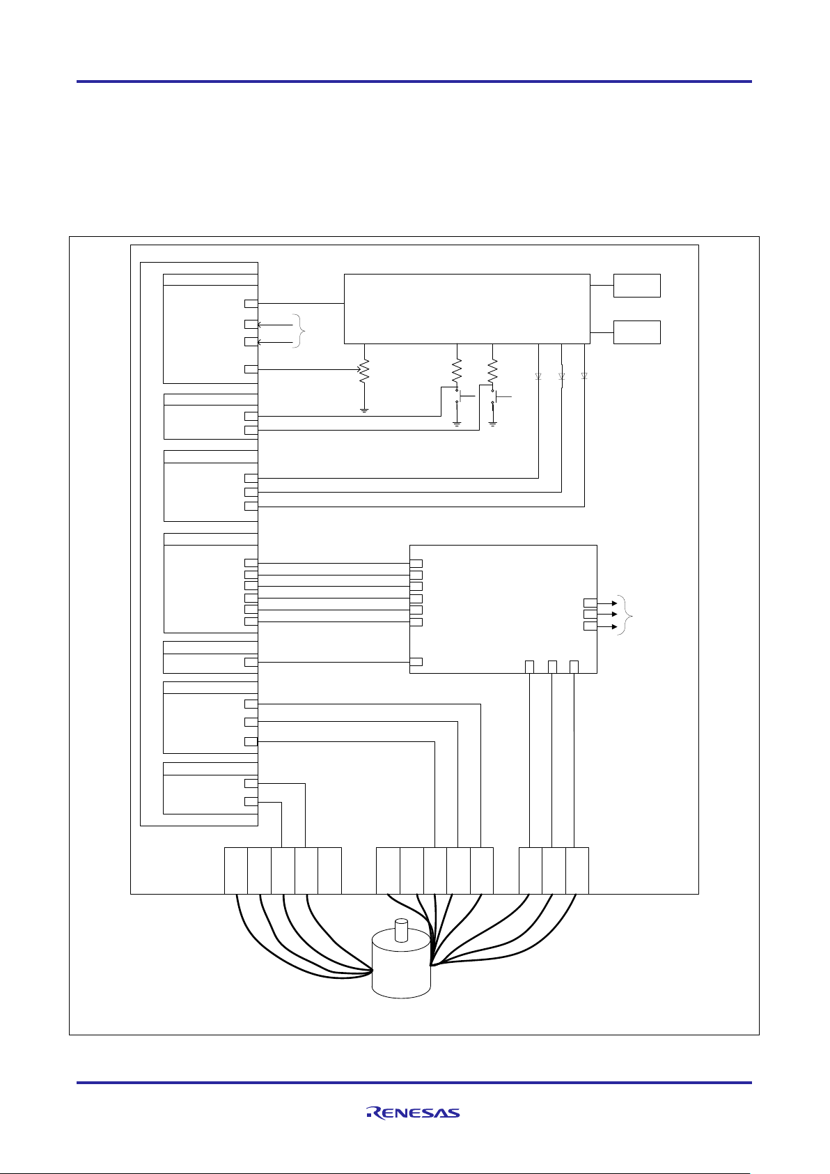
2.1 Hardware configuration
The hardware configuration is shown below.
Figure 2-1 Hardware Configuration Diagram
R01AN5790EJ0100 Rev.1.00 Page 4 of 41
Mar.12.21
Page 5

RX13T
Vector Control for Permanent Magnet Synchronous Motor
with Encoder (Implementation)
Item
Interface component
Function
Rotation position /
Variable resistor (VR1)
Reference value of rotation position / speed input
START/STOP
Toggle switch (SW1)
Motor rotation start/stop command
ERROR RESET
Push switch (SW2)
Command of recovery from error status
LED1
Orange LED
• At the time of motor rotation: ON
• At the time of stop: OFF
LED2
Orange LED
• At the time of error detection: ON
At the time of normal operation: OFF
LED3
Orange LED
• Complete of positioning: ON
Uncomplete of positioning: OFF
RESET
Push switch (RESET1)
System reset
R5F513T5ADFL port name
Function
P46 / AN006
Inverter bus voltage measurement
P47 / AN007
For position / speed command value input (analog value)
PB5
START/STOP toggle switch
PB4
ERROR RESET toggle switch
PD6
LED1 ON/OFF control
PD4
LED2 ON/OFF control
PB3
LED3 ON/OFF control
P40 / AN000
U phase current measurement
P42 / AN002
W phase current measurement
P71 / MTIOC3B
PWM output (Up) / Low active
P72 / MTIOC4A
PWM output (Vp) / Low active
P73 / MTIOC4B
PWM output (Wp) / Low active
P74 / MTIOC3D
PWM output (Un) / High active
P75 / MTIOC4C
PWM output (Vn) / High active
P76 / MTIOC4D
PWM output (Wn) / High active
P93 / IRQ0
Hall Phase-U signal input
P94 / IRQ1
Hall Phase-V signal input
PA2 / IRQ4
Hall Phase-W signal input
PB1 / MTCLKA
Encoder Phase-A signal input
PB0 / MTCLKB
Encoder Phase-B signal input
PE2 / POE10#
PWM emergency stop input at the time of over-current detection
2.2 Hardware specifications
2.2.1 User interfaces
List of user interfaces of this system is given in Table 2-1.
Table 2-1 User Interfaces
speed
List of port interfaces of this system is given in Table 2-2.
Table 2-2 Port Interfaces
(analog value)
•
•
R01AN5790EJ0100 Rev.1.00 Page 5 of 41
Mar.12.21
Page 6

RX13T
Vector Control for Permanent Magnet Synchronous Motor
with Encoder (Implementation)
•
measurement
•
2.2.2 Peripheral functions
List of the peripheral functions used in this system is given in Table 2-3.
Table 2-3 List of the Peripheral Functions
12-bit A/D CMT MTU3 POE3C
Rotation speed command value
input
• Current of each phase U and W
measurement
1 [ms] interval timer
Complementary PWM output
• Encoder phase counter
• Encoder count capture
• Inverter bus voltage
(1) 12-bit A/D converter (S12ADF)
U phase current (I
W phase current (Iw), inverter bus voltage (Vdc) and rotation speed reference are
u),
measured by using the single scan mode (use hardware trigger). The sample-and-hold function is used for
U phase current (I
and W phase current (Iw) measurement.
u)
(2) Compare match timer (CMT)
The channel 0 of the compare match timer is used as 1 [ms] interval timer.
(3) Multi-function timer pulse unit 3 (MTU3c)
The operation mode varies depending on channels. On the channels 3 and 4, output (p-side is active low,
n-side is active high) with dead time is performed by using the complementary PWM mode.
The channel 1 of MTU3 operate in phase counting mode, the counter is incremented or decremented
according to the phase difference between Phase-A and Phase-B signals from the encoder.
The channel 0 of MTU3 is used as free-run timer for speed measurement.
(4) Port output enable 3 (POE3C)
PWM output ports are set to high impedance state when an overcurrent is detected (when a falling edge of
the POE10# port is detected).
Set PWM output ports to high
impedance state to stop the PWM
output.
R01AN5790EJ0100 Rev.1.00 Page 6 of 41
Mar.12.21
Page 7
RX13T
Vector Control for Permanent Magnet Synchronous Motor
with Encoder (Implementation)
r_mtr_common.h: Common definition
(Project Folder)
‘In Circuit Scope’) is attached to the name of folders, files, functions, variables related to ‘Renesas Motor Workbench’.
demo
motor_module
application
controller
lib
ics
lib
ref
src
controller
functions
mode
main.h, main.c: User main function
r_mtr_board.h, r_mtr_board.c: Function definition for board UI
r_mtr_ctrl_mcu.h: Common definition depends on MCU
r_mtr_config.h: Common definition for software configuration
r_mtr_control_parameter.h: Configuration definition for control parameters
r_mtr_ipd.h, r_mtr_ipd.obj: Function definition of IPD controller
speed observer
r_mtr_ics.h, r_mtr_ics.c: Function definition for Analyzer UI
r_mtr_ctrl_encoder.h, r_mtr_ctrl_encoder.c: Function definition of encoder
r_mtr_mod.h, r_mtr_mod.c: Function definition for modulation
r_mtr_statemachine.h, r_mtr_statemachine.c:
src
smc_gen
Smart Configurator generated driver, API
Smart Configurator configuration file
r_mtr_ctrl_mrssk.h, r_mtr_ctrl_mrssk.c:
Function definition depends on inverter
r_mtr_driver_access.h, r_mtr_driver_access.c: User access function definition
2.3 Software configuration
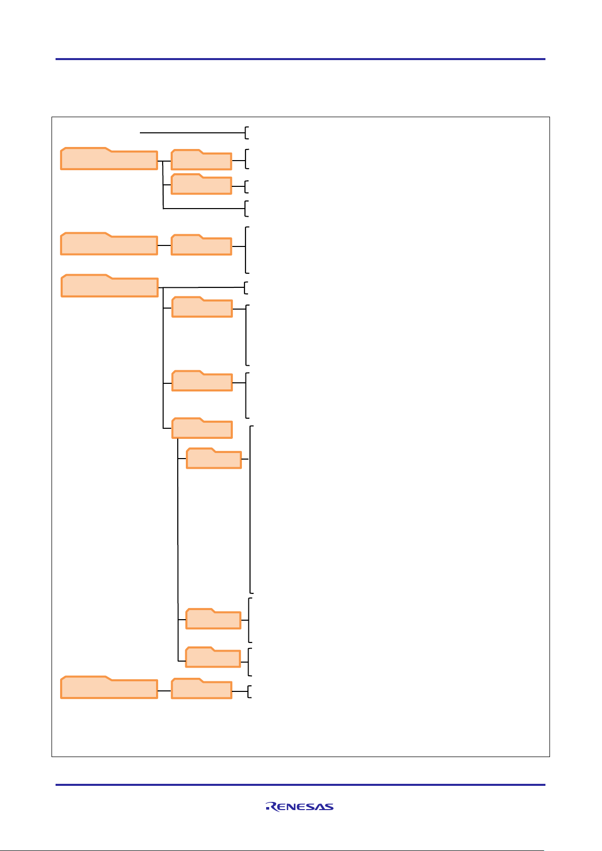
2.3.1 Software file configuration
Folder and file configuration of the sample programs are given below.
RX13T_MRSSK2_SPM_ENCD_FOC_xxx_RVyyy*1:
ICS2_RX13T.lib: Communication library for GUI tool
ICS2_RX13T.h: Function definition for GUI tool
r_mtr_interrupt.c: Interrupt function definition for Analyzer*
r_mtr_volt_err_comp.h, r_mtr_volt_err_comp.obj: Function definition for voltage
error compensation
r_mtr_ctrl_gain_calc.obj: Function definition for calculation of control gains
r_mtr_speed_observer.h, r_mtr_speed_observer.obj: Function definition for
2
r_mtr_motor_parameter.h: Configuration definition for motor parameters
r_mtr_inverter_parameter.h: Configuration definition for inverter parameters
r_mtr_pi_control.h, r_mtr_pi_control.c: Function definition for PI control
r_mtr_transform.h, r_mtr_transform.c: Function definition for coordinate transform
r_mtr_foc_control_encd_position.h, r_mtr_foc_control_encd_position.c:
r_mtr_foc_current.h, r_mtr_foc_current.c: Function definition for current control
r_mtr_foc_speed.h, r_mtr_foc_speed.c: Function definition for speed control
r_mtr_foc_position.h, r_mtr_foc_position.c: Function definition for position control
r_mtr_interrupt_carrier.c: Function definition of carrier interrupt
r_mtr_interrupt_1ms.c: Function definition of 1ms interrupt
r_mtr_interrupt_sensor.c: Function definition of sensor signal interrupt
r_mtr_parameter.h: Various parameter definition
r_mtr_position_profiling.h, r_mtr_position_profiling.c: Function definition of
r_mtr_ctrl_rx13t.h, r_mtr_ctrl_rx13t.c: Function definition depends on MCU
r_mtr_ctrl_hall.h, r_mtr_ctrl_hall.c: Function definition of hall
r_mtr_filter.h, r_mtr_filter.c: Function definition for general purpose filters
r_mtr_foc_action.c: Action function definition
Function definition of FOC control
position profiling.
Function definition for state transition
Notes: 1. xxx: CSP refers to CS+ version. E2S refers to e2 studio version. yyy: revision version number eg. 100: Rev.version 1.00
2 Regarding the specification of Analyzer function in the motor control development support tool ‘Renesas Motor
Workbench’, please refer to the section 4.The identifier ‘ics/ICS (ICS is previous motor control development support tool
Figure 2-2 Folder and file configuration
R01AN5790EJ0100 Rev.1.00 Page 7 of 41
Mar.12.21
Page 8

RX13T
Vector Control for Permanent Magnet Synchronous Motor
with Encoder (Implementation)
(Smart Configurator Output Folder)
src
smc_gen
Config_PORT
Config_S12AD0
Config_IWDT
Peripherals driver for GPIO ports. Unused ports are also configured here.
Config_CMT0
Config_POE
Config_befoc
General*
3
r_bsp*
3
r_config*
3
r_pincfg*
3
Peripheral driver for single scan mode 12-bit A/D conversion for VR1
Peripheral driver for watch-dog timer.
Config_IWDT_user.c: User function for Watchdog timer
Peripheral driver for compare match timer of 1ms interval
Config_CMT0_user.c: User function for Compare match timer
Peripheral driver for port output enable that places PWM output in
Config_POE_user.c: User function for Port Output Enable
Peripheral drivers for multi-function timer pulse unit (MTU) and 12-bit A/D converter
for Motor control
r_cg_hardware_setup.c: Peripheral initialization
< various BSP package files *1 >
BSP: Board Support Package
Notes: 1. Regarding BSP package files, please refer to README.txt file in <r_bsp> folder
3. Refer to Section 6.2 in “RX Smart Configurator User’s Guide:e2 studio (R20AN0451)” for explanation of these files and folder
< for FIT configuration files*2 >
< for pin code generation >
Config_MTU0
Peripheral driver for Normal Mode Timer configuration for speed measurement
Config_MTU0_user.c: User function to process interrupt for speed calculation
Config_MTU1
Peripheral driver for Normal Mode Timer configuration for phase measurement
Config_ICU
Peripheral driver to configure interrupt requests for external Hall interrupt
Config_ICU_user.c: User function for Hall interrupt service
2.3.2 Smart Configurator File Configuration
Peripheral drivers were configured easily by using Smart Configurator tool for this project. In this tool, a
dedicated configurator for motor drive application related peripherals is used to configure multi-function timer
and 12-bit A/D converter.
Smart Configurator saves information such as the target MCU, peripheral, clock and pin functions setting for
the project in *.scfg file.
Refer to the file, RX13T_MRSSK2_SPM_ENCD_FOC_xxx_RVyyy.scfg, in the root folder to see the
peripheral settings of this project.
(xxx: CSP refers to CS+ version. E2S refers to e
Folder and file configuration of Smart Configurator generated output are shown below.
Config_PORT.h, Config_PORT.c: Driver and API for Port
Config_PORT_user.c: User function for Port
Config_S12AD0.h, Config_S12AD0.c: Driver and API for AD port
Config_S12AD0_user.c: User function for AD function of Board UI
Config_IWDT.h, Config_IWDT.c: Driver and API for Watchdog timer
2
studio version. yyy: revision version number)
Config_CMT0.h, Config_CMT0.c: Driver and API for Compare match timer
high-impedance state when over-current or output short-circuit occurs
Config_POE.h, Config_POE.c: Driver and API for Port Output Enable
Config_MTU0.h, Config_MTU0.c: Driver and API for free-run timer
Config_MTU1.h, Config_MTU1.c: Driver and API for phase counting mode
Config_MTU1_user.c: User function to start timer
Config_ICU.h, Config_ICU.c: Driver and API for IRQ external pin interrupt
(S12AD) for basic motor control.
Config_befoc.h, Config_befoc.c: Driver and API for Multi-function timer and AD
Config_befoc_user.c: User function for Multi-function timer and AD conversion
r_smc_entry.h: Includes header files of generated code of peripheral drivers added to
<various header files> project
conversion for Motor control
FIT: Firmware Integration Technology
2. r_config is created by e2studio project creation utilizing Smart Configurator tool. FIT is not used in this sample software
Figure 2-3 Smart Configurator Folder and File Configurations
R01AN5790EJ0100 Rev.1.00 Page 8 of 41
Mar.12.21
Page 9

RX13T
Vector Control for Permanent Magnet Synchronous Motor
with Encoder (Implementation)
Type of motor
Type of sensor
Motor drive method
s: stepping motor
r: resolver
foc: field-oriented control
void R_Config_befoc_Create_UserInit(void)
/* End user code. Do not edit comment generated here */
/* Configure S12AD as single scan mode AD converter */
S12AD.ADSTRGR.WORD = _0900_MTR_AD_TRSA_TRG4AN;
Smart Configurator Motor component configuration name is named according to the following convention.
Configuration filename format: Config_<Type of motor><Type of sensor><Motor drive method>
The table below shows various motor types, sensor types and motor drive method for defining the Motor
configuration filename.
Table 2-4 Smart Configurator Motor configuration filename format
b: brushless DC Motor (BLDC)
i: induction motor
e: encoder
m: magnetic encoder
120: 120-degree conduction control
s: sensor-less
h: hall sensor
In this project, the type of motor used is BLDC motor and driven with encoder field-oriented control. Therefore,
the configuration name is Config_befoc.
Tips:
The application-specific Smart Configurator Motor component is presented in a simple and easy to
understand GUI that consolidates several peripherals to configure peripherals required for basic motor drive
in one interface. These peripherals include the multi-function timer pulse unit (MTU) and AD converter.
While benefiting from the ease of configuring Motor driver related peripherals in single interface, it is important
to note that the Motor component set-up the same registers that could been set-up by other components, (eg.
AD converter) and vice-versa. This will cause overwriting of registers that are commonly set-up by both the
Motor or AD converter component. This is expected and user must pay attention to these circumstances and
to take appropriate countermeasure. User can make use of the generated <Configuration_name>_user.c of
affected component to perform the countermeasure.
An example can be found in this project in the Config_befoc_user.c file. This file implements the device driver
for Motor peripheral module of Smart Configurator. In its user’s initialization API, A/D Channel select register
S12AD.ADANSA0 is updated to select AN007 as highlighted in the sample code below.
{
/* Start user code for user init. Do not edit comment generated here */
R_Config_befoc_StartTimerCount();
R_Config_befoc_StartAD();
R_Config_MTU1_Start();
R_Config_MTU0_Start();
S12AD.ADANSA0.WORD |= _0080_AD_ANx07_USED;
An overwriting of S12AD.ADANSA0 register occurred in Config_befoc.c file that caused AN007 to be
deselected. Below shows the code in Config_befoc.c where the overwriting of S12AD.ADANSA0 occurred.
S12AD.ADCSR.WORD = _0000_MTR_AD_SINGLE_SCAN_MODE;
S12AD.ADANSA0.WORD = _0001_MTR_AD_AN000_USED | _0004_MTR_AD_AN002_USED |
_0040_MTR_AD_AN006_USED;
R01AN5790EJ0100 Rev.1.00 Page 9 of 41
Mar.12.21
Page 10

RX13T
Vector Control for Permanent Magnet Synchronous Motor
with Encoder (Implementation)
/* Set channels and sampling time */
S12AD.ADSSTR7 = _0D_AD0_SAMPLING_STATE_7;
AN007 had been selected earlier in Config_S12AD0.c file in R_Config_S12AD0_Create API. Below shows
the code where AN007 was originally selected when A/D converter peripheral driver was set-up.
S12AD.ADANSA0.WORD = _0080_AD_ANx07_USED;
R01AN5790EJ0100 Rev.1.00 Page 10 of 41
Mar.12.21
Page 11
RX13T
Vector Control for Permanent Magnet Synchronous Motor
with Encoder (Implementation)
Application Layer (User Application)
main.c
User Interface Module
Main
r_mtr_ics.c
r_mtr_board.c
Middle Layer (Motor Control Process)
r mtr driver access.c
Interface Module
Control Module (FOC, Feedback Loop Control)
r_mtr_interrupt_carrier.c
r_mtr_foc_control_encd_position.c
r_mtr_foc_current.c
r_mtr_interrupt_1ms.c
r_mtr_interrupt_sensor.c
r_mtr_foc_speed.c
r_mtr_foc_position.c
Other Control Modules
Device Layer (MCU Register Access, Inverter Driver, Sensor Driver)
Inverter Module
r_mtr_ctrl_mrssk.c
r_mtr_ctrl_encoder.c
r_mtr_ctrl_hall.c
MCU Module
r_mtr_interrupt.c
r_mtr_ctrl_rx13t.c
H/W Layer (MCU Inverter)
Function Call
Function Call
Set User Command to Buffer
Set Control Gain & Command
Set PWM duty
Get Voltage, Current & Angle/Speed
Interrupt Process Modules
Control Modules
Get A/D Converter Data & Sensor Signal
Output PWM Signal
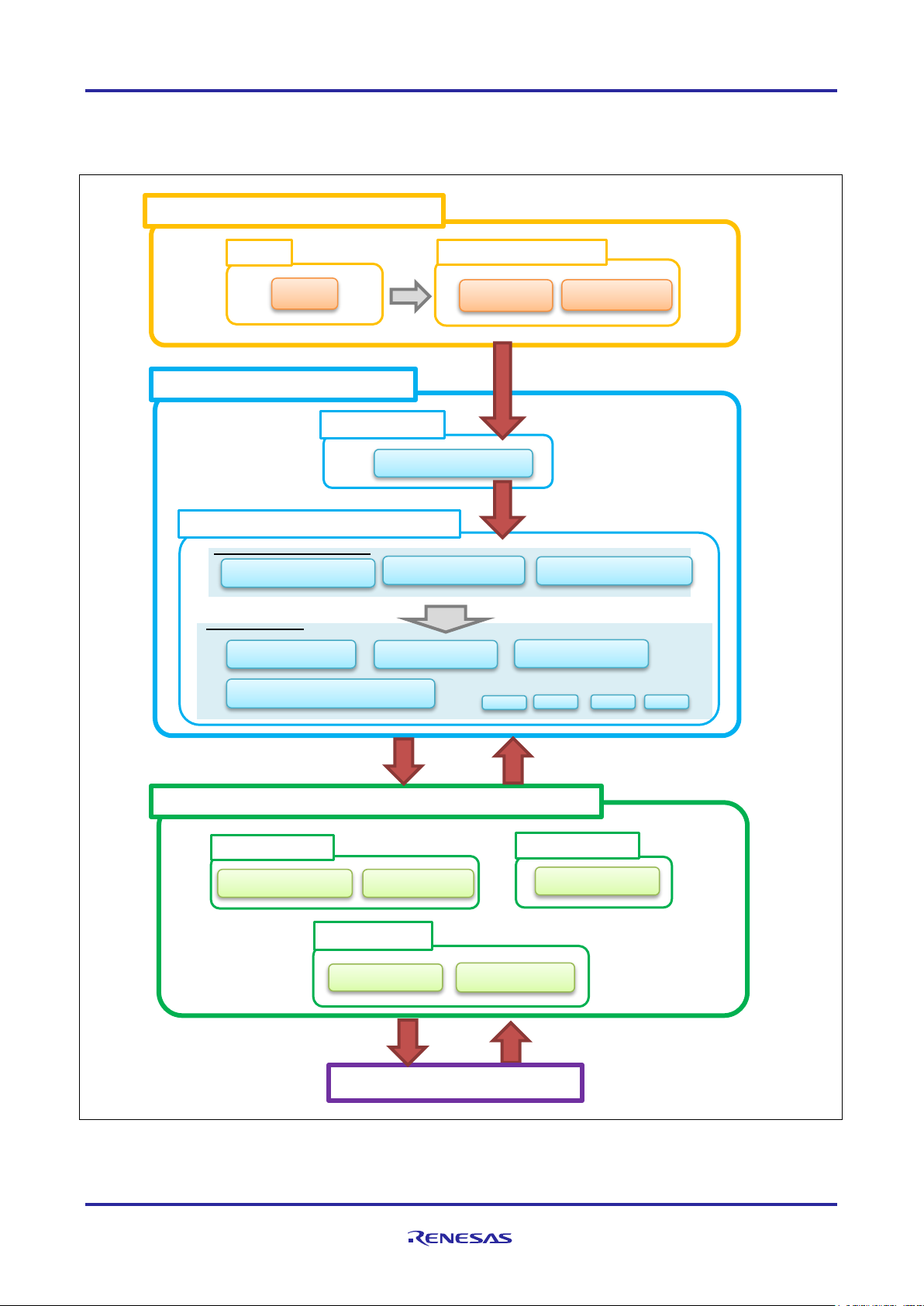
2.3.3 Module configuration
Module configuration of the sample programs is described below.
Figure 2-4 Module Configuration
R01AN5790EJ0100 Rev.1.00 Page 11 of 41
Mar.12.21
Page 12

RX13T
Vector Control for Permanent Magnet Synchronous Motor
with Encoder (Implementation)
Item
Content
Control method
Vector control
from Analyzer
Position detection of rotor
Incremental encoder (A-B Phase), Hall sensor (UVW Phase)
Input voltage
DC 24 [V]
Main clock frequency
32 [MHz]
Carrier frequency (PWM)
20 [kHz] (carrier cycle: 50 [µs])
Dead time
2 [μs]
(Current loop)
Control cycle
1 [ms]
-180° to 180°
ICS UI
Position command generation: Position profile of
Accuracy of position
0.3° (Encoder pulse: 300[ppr] 4 for multiplying 1200 [cpr])
Dead band of position *
Encoder count ±1 [cpr] (±0.3°)
Position control system: 10 Hz
Optimization setting for
Optimization level
2 (-optimize = 2) (default)
Optimization method
Size priority (default)
ROM/RAM size
ROM: 23.1 KB
port is detected), the PWM output ports are set to high impedance state.
2.4 Software specifications
Table 2-5 shows basic software specification of this system. For details of the vector control, refer to the
application note ‘Vector control of permanent magnet synchronous motor with encoder: algorithm’.
Table 2-5 Basic Specifications of Vector Control PMSM with Encoder Software
Motor control start/stop Determined depending on the level of SW1 (“Low”: control start “High”: stop) or input
magnetic pole
Control cycle
(Speed and Position loop)
Management of position
command value
Management of speed
command value
Natural frequency of each
control system
compiler
100 [μs] (twice the carrier cycle)
Board UI Position command generation: Direct input of VR1
(input range)
trapezoidal curve for speed command value
(input range)
-32768° to 32767°
(Max speed)
CW / CCW: 2000 [rpm]
CW: 0 [rpm] to 2000 [rpm]
CCW: 0 [rpm] to 2000 [rpm]
Current control system: 300 Hz
Speed control system: 30 Hz
RAM: 5.6 KB
Processing stop for protection Motor control signal outputs (six outputs) will be disabled, under any of the following
conditions.
1.
Current of each phase exceeds 3.82 [A] (monitored every 100 [μs])
Inverter bus voltage exceeds 28 [V] (monitored every 100 [μs])
2.
Inverter bus voltage is less than 14 [V] (monitored every 100 [μs])
3.
4. Rotation speed exceeds 3000 [rpm] (monitored every 100 [μs])
When an external over current signal is detected (when a falling edge of the POE10#
Note: * Dead zone is provided to prevent hunting in positioning.
R01AN5790EJ0100 Rev.1.00 Page 12 of 41
Mar.12.21
Page 13

RX13T
Vector Control for Permanent Magnet Synchronous Motor
with Encoder (Implementation)
Item
Conversion ratio
(Command value: A/D conversion value)
Channel
Rotation position
command value
CW
0° to 180°: 07FFH to 0000H
AN007
CCW
0° to -180°: 0800H to 0FFFH
Rotation speed
CW
0 [rpm] to 2000[rpm]: 07FFH to 0000H
CCW
0 [rpm] to 2000[rpm]: 0800H to 0FFFH
Item
Conversion ratio
(Inverter bus voltage: A/D conversion value)
Channel
Inverter bus voltage
0 [V] to 111 [V]: 0000H to 0FFFH
AN006
Item
Conversion ratio
(U, W phase current: A/D conversion value)
Channel
U, W phase current
-12.5 [A] to 12.5 [A]: 0000H to 0FFFH *
Iu: AN000
3. Descriptions of the Control Program
The target sample programs of this application note are explained here.
3.1 Contents of Control
3.1.1 Motor Start/Stop
The start and stop of the motor are controlled by input from Analyzer function of ‘Renesas Motor Workbench’
or SW1 switch of inverter board.
A general-purpose port is assigned to SW1. The port is read within the main loop. When the port is at a ‘Low’
level, the software determines that the motor should be started. Conversely, when the level is switched to
‘High’, the program determines that the motor should be stopped.
3.1.2 A/D Converter
(1) Motor Rotation Position and Speed Command Value
The motor rotation position and speed command value can be set by Analyzer input or A/D conversion of
the VR1 output value (analog value). The A/D converted VR1 value is used as rotation speed command
value, as shown below.
Table 3-1 Conversion Ratio of the Rotation Position and Speed Command Value
command value
(2) Inverter Bus Voltage
Inverter bus voltage is measured as given in Table 3-2.
It is used for modulation factor calculation, under-voltage detection and over-voltage detection. (When an
abnormality is detected, PWM is stopped.)
Table 3-2 Inverter Bus Voltage Conversion Ratio
(3) U, W Phase Current
The U and W phase currents are measured as shown in Table 3-3 and used for vector control.
Table 3-3 Conversion Ratio of U and W Phase Current
Note: * For more details of A/D conversion characteristics, refer to RX13T Group User’s Manual: Hardware.
.
Iw: AN002
R01AN5790EJ0100 Rev.1.00 Page 13 of 41
Mar.12.21
Page 14

RX13T
Vector Control for Permanent Magnet Synchronous Motor
with Encoder (Implementation)
u1_ref_pos_status
u1_ref_pos_mode
Time[s]
Time[s]
Speed
Position
Constant Speed
com_u2_max_speed_rpm
com_u2_pos_interval_time
MTR_CTRL_TRIANGLE
MTR_CTRL_TRAPEZOIDAL
MTR_CTRL_TRIANGLE : f4_accel_max_speed * f4_accel_time >= f4_pos_dt_rad
MTR_CTRL_TRAPEZOIDAL : f4_accel_max_speed * f4_accel_time < f4_pos_dt_rad
com_s2_ref_position_deg
MTR_POSITION_STEADY_STATE
MTR_POSITION_TRANSITION_STATEE
MTR_POSITION_STEADY_STATE
MTR_POSITION_TRANSITION_STATE
com_s2_ref_position_deg
Reference
Position
3.1.3 Position Profile Generation (Position Profile of Trapezoidal Curve for Speed Command Value)
In vector control software for PMSM with encoder, the position profile generation is used to create command
value (input position value). The implementation of command value is each control cycle is used as method of
managing acceleration and the maximum speed value with respect to target position value.
E
Figure 3-1 Position Profile Generation
Enter the following variables from the Analyzer to create a command value.
• Position reference [degree] (com_s2_ref_position_deg)
• Acceleration time (com_f4_accel_time)
• Maximum speed command value (com_u2_max_speed_rpm)
• Position stabilization wait time (com_u2_pos_interval_time)
R01AN5790EJ0100 Rev.1.00 Page 14 of 41
Mar.12.21
Page 15

RX13T
Vector Control for Permanent Magnet Synchronous Motor
with Encoder (Implementation)
2π/Pulses per Rotation
Timer Counter
Capture Capture
Counter Difference
Phase-A
Encoder Signal
Phase
-B
Encoder Signal
2π/Pulses per Rotation
CaptureCaptureCaptureCaptureCapture
MTU0.TCNT
3.1.4 Speed Measurement
In order to obtain better real-time performance and higher speed resolution at low speed, this system use
encoder signal edge interval to calculate speed, the speed extrapolation is used in PI control calculation. In
addition, taking the difference between rise time and fall time and the accuracy of quadrature of encoder
signal into consideration, the speed is calculated with time elapsed and angle changed in one period of
encoder Phase-A or Phase-B signals.
(1) Speed Calculation
Motor Rotation Speed[rad/s] =
Figure 3-2 Speed Calculation using Encoder
/
R01AN5790EJ0100 Rev.1.00 Page 15 of 41
Mar.12.21
Page 16

RX13T
Vector Control for Permanent Magnet Synchronous Motor
with Encoder (Implementation)
U V
W
ωt
ωt
ω
t
ωt
Modulation wave: command voltage
Carrier wave (triangular wave): PWM timer count
U phase switching
waveform
V phase switching
waveform
Voltage between U – V
Lines: (U phase waveform)
ー(V phase waveform
)
3.1.5 Modulation
The target software of this application note uses pulse width modulation (hereinafter called PWM) to generate
the input voltage to the motor. And the PWM waveform is generated by the triangular wave comparison
method.
(1) Triangular Wave Comparison Method
The triangular wave comparison method is used to output the voltage command value. By this method, the
pulse width of the output voltage can be determined by comparing the carrier waveform (triangular wave)
and voltage command value waveform. The voltage command value of the pseudo sinusoidal wave can
be output by turning the switch on or off when the voltage command value is larger or smaller than the
carrier wave respectively.
Figure 3-3 Conceptual Diagram of the Triangular Wave Comparison Method
R01AN5790EJ0100 Rev.1.00 Page 16 of 41
Mar.12.21
Page 17

RX13T
Vector Control for Permanent Magnet Synchronous Motor
with Encoder (Implementation)
Average
voltage
t
V
T
ON
T
OFF
T
ON
+ T
OFF
T
ON
Duty =
× 100 [%]
E
V
m =
m: Modulation factor V: Voltage command value E: Inverter bus voltage
Here, as shown in the Figure 3-4, ratio of the output voltage pulse to the carrier wave is called duty.
Figure 3-4 Definition of Duty
Modulation factor m is defined as follows.
The voltage command can be generated by setting PWM compare register properly to obtain the desired
duty.
R01AN5790EJ0100 Rev.1.00 Page 17 of 41
Mar.12.21
Page 18

RX13T
Vector Control for Permanent Magnet Synchronous Motor
with Encoder (Implementation)
SYSTEM MODE
INACTIVE
ERROR
POWER ON/
RESET
[RESET EVENT]
[ACTIVE EVENT]
[INACTIVE EVENT]
[ERROR EVENT]
RUN MODE
INIT
BOOT
Control Config
Current
Speed
Position
Torque
Voltage
DRIVE
ACTIVE
[MTR_ID_ZERO_CONST
== st_g.u1_flag_id_ref
]
[g_f4_offset_calc_time
== st_g.u2_cnt_adjust]
[ERROR EVENT]
[RESET EVENT]
EVENT
INACTIVE
ACTIVE
ERROR
RESET
MODE
INACTIVE ACTIVE ERROR
INACTIVE
INACTIVE INACTIVE
ACTIVE
ERROR ERROR
ERROR
ERROR
ERROR
INACTIVE
ACTIVE
ERROR
[MTR_LOOP_POSITION ==
com_u1_ctrl_loop_mode
]
[MTR_LOOP_SPEED ==
com_u1_ctrl_loop_mode
]
Control Config
Current
Speed
Position
Torque
Voltage
Control Config
Current
Speed
Position
Torque
Voltage
EVENT name
Occurrence factor
INACTIVE
by user operation
ACTIVE
by user operation
ERROR
when the system detects an error
RESET
by user operation
3.1.6 State Transition
Figure 3-5 is a state transition diagram of the vector control software. In the target software of this application
note, the software state is managed by ‘SYSTEM MODE’ and ‘RUN MODE’. And ‘Control Config’ shows the
active control system in the software.
Figure 3-5 State Transition Diagram of Vector Control PMSM with Encoder Software
(1) SYSTEM MODE
‘SYSTEM MODE’ indicates the operating states of the system. The state transits on occurrence of each
event (EVENT). ‘SYSTEM MODE’ has 3 states that are motor drive stop (INACTIVE), motor drive
(ACTIVE), and abnormal condition (ERROR).
(2) RUN MODE
‘RUN MODE’ indicates the condition of the motor control. ‘RUN MODE’ transits sequentially as shown in
Figure 3-5 when ‘SYSTEM MODE’ is ‘ACTIVE’.
(3) EVENT
When ‘EVENT’ occurs in each ‘SYSTEM MODE’, ‘SYSTEM MODE’ changes as shown the table in Figure
3-5, according to that ‘EVENT’.
Table 3-4 List of EVENT
R01AN5790EJ0100 Rev.1.00 Page 18 of 41
Mar.12.21
Page 19

RX13T
Vector Control for Permanent Magnet Synchronous Motor
with Encoder (Implementation)
MTR_ID_CONST
(
1)
I
d
reference
[
A]
I
q
reference
[
A]
Speed reference
[rpm]
com
_
f4
_ref
_
id
MTR_
ID
_ZERO
_CONST
(
3)
I
d
=0
control
MTR_
MODE
_BOOT
RUN MODE
I
d
reference status
speed PI output
0
0
0
I
q
reference status
Speed reference status
MTR_
MODE
_INIT
MTR_
ID
_UP
(
0)
MTR_
ID
_ZERO
_CONST
(
3)
MTR_
I
Q_
ZERO_
CONST
(0
)
MTR
_
SPEED_
ZERO_
CONST
(0
)
MTR_
IQ
_SPEED
_PI
_
OUTPUT
(
1
)
MTR
_POSITION
_CONTROL
_
OUTPUT
(
1
)
MTR
_
MODE_
DRIVE
MTR
_ID
_CONST
(
1)
MTR_
ID
_UP
(
0)
MTR
_POSITION
_
CONST
(
0
)
Position reference status
MTR
_POSITION
_
TRAPEZOID
(
1
)
Position reference
[
degree
]
0
com
_
s2
_ref_position_deg
[
s
]
[s
]
[
s]
[
s]
MTR_ID_CO NST
(1)
Id reference[A]
Iq reference[A]
Speed reference
[rpm]
com_f4_ref _id
MTR_ID_ZERO_CONS T
(3)
z
Id=0 control
MTR_MODE_B OOT
RUN MO DE
I
d
reference status
speed PI output
0
0
0
Iq reference status
Speed reference status
MTR_MODE_IN IT
MTR_ID_UP
(0)
MTR_ID_ZERO_CONS T
(3)
MTR_IQ_ZERO_CONS T
(0)
MTR_SP EED_ZERO_CO NST
(0)
MTR_IQ_SP EED_PI_O UTPU T
(1)
MTR_SP EED_CHANGE
(2)
MTR_MODE_D RIVE
MTR_ID_CO NST
(1)
MTR_ID_UP
(0)
[s]
[s]
[s]
com_s2_ref _speed_ rpm
3.1.7 Startup Method
Figure 3-6 shows the software implementation of d-axis and encoder alignment method. The d-axis alignment
method used as startup control of position control method, in initialization mode (MTR_MODE_INIT) and Boot
mode (MTR_MODE_BOOT). In drive mode (MTR_MODE_DRIVE) vector control is implemented for PMSM
with Encoder. Each reference value setting of d-axis current, q-axis current and speed is managed by
respective status.
Figure 3-6 Startup Position Control of Vector Control PMSM with Encoder Software
For details of the position control of a vector controlled PMSM using encoder, refer to the application note
‘Vector control of permanent magnet synchronous motor with encoder: algorithm’.
Figure 3-7 Startup Speed Control of Vector Control PMSM with Encoder Software
R01AN5790EJ0100 Rev.1.00 Page 19 of 41
Mar.12.21
Page 20

RX13T
Vector Control for Permanent Magnet Synchronous Motor
with Encoder (Implementation)
Over-current error
Over-current limit value [A]
3.82
Monitoring cycle [µs]
100
Over-voltage error
Over-voltage limit value [V]
28
Monitoring cycle [µs]
100
Under-voltage error
Under-voltage limit value [V]
14
Monitoring cycle [µs]
100
Over-speed error
Speed limit value [rpm]
3000
Monitoring cycle [µs]
100
3.1.8 System Protection Function
This control program has the following error status and executes emergency stop functions in case of
occurrence of respective errors. Table 3-5 shows each setting value for the system protection function.
• Over-current error
The over current detection is performed by both hardware detection method as well as software detection
method. In response to over-current detection an emergency stop signal is generated from the hardware
(hardware detection). When the emergency stop signal is generated, the PWM output ports are set to high
impedance state.
In addition, U, V, and W phase currents are monitored in over current monitoring cycle. When an over
current is detected, the CPU executes emergency stop (software detection). The over current limit value is
calculated from the nominal current of the motor [MP_NOMINAL_CURRENT_RMS].
• Over-voltage error
The inverter bus voltage is monitored in over-voltage monitoring cycle. When an over-voltage is detected,
the CPU performs emergency stop. Here, the over-voltage limit value is set in consideration of the error of
resistance value of the detect circuit.
• Under-voltage error
The inverter bus voltage is monitored in under-voltage monitoring cycle. The CPU performs emergency
stop when under-voltage is detected. Here, the low voltage limit value is set in consideration of the error of
resistance value of the detect circuit.
• Over-speed error
The rotation speed is monitored in rotation speed monitoring cycle. The CPU performs emergency stop
when the speed is over the limit value.
Table 3-5 Setting Values of the System Protection Function
R01AN5790EJ0100 Rev.1.00 Page 20 of 41
Mar.12.21
Page 21

RX13T
Vector Control for Permanent Magnet Synchronous Motor
with Encoder (Implementation)
Decoupl ing
Control
PWM
Current
PI
Speed
PI
dq
UVW
dq
UVW
Encoder
ω*
i
d
*
ω
i
q
*
v
d
*
θ
i
d
i
q
i
u
i
w
θ
v
u
v
v
v
w
+
-
+
+
Positi on P
+ Speed F F
θ*
θ
i
q
i
d
vd**
v
q
**
Voltage
Limit
iq**
v
q
* vq*
M
Voltage
err or
Compe n
-sati on
v
u
v
v
v
w
Hal l
Encod er Interrup t
Carrier Interrupt
Switch Position & Speed
Calculation Mode
ω
θ
Switch
Positi on/Speed
Loop mode
Speed
Obse rver
Positi on
Profil ing
θ_
refe ren ce
IPD Con troler
+ Positi on P + Speed F F
Switch
Positi on/Speed L oop Control ler
Carrier I nterru pt Process
1ms Interrup t Process
Encoder Interrupt Process
Encod er
A/B
Phase
sign al
ω*
ω*
iq*id*
ω
_
refe ren ce
Hall I nte rru pt
Process
Rotor A ngle
Detection
Switch Angle
Adj ust mod e
File name
Function name
Process overview
• Current PI control
Speed PI control
• Disable Hall interrupt
Speed calculation
3.2 Function Specifications of Vector Control using Encoder Software
The control process of the target software of this application note is mainly consisted of 100[µs] period
interrupt (carrier interrupt) and 1[ms] period interrupt. As following Figure 3-8, the control process in the red
broken line part is executed every 100[µs] period, and the control process in the blue broken line part is
executed every 1[ms] period.
Figure 3-8 System Block of Vector Control with Encoder
This chapter shows the specification of 4 interrupt functions and functions executed in each interrupt cycle. In
the following tables, only essential functions of the vector control are listed. Regarding the specification of
functions not listed in following tables, refer to source codes.
Table 3-6 List of Control Functions ‘mtr_interrupt.c’
r_mtr_interrupt_carrier.c mtr_foc_carrier_interrupt
Input: (mtr_foc_control_t *) st_foc / Structure pointer for
vector control Output: None
r_mtr_interrupt_1ms.c mtr_foc_1ms_interrupt
Input: (mtr_foc_control_t *) st_foc / Structure pointer for
vector control
Output: None
r_mtr_interrupt_sensor.c mtr_angle_adj_hall_interrupt
Input: (mtr_foc_control_t *) st_foc / Structure pointer for
vector control
Output: None
mtr_encd_pos_speed_calc_interrupt
Input: (mtr_foc_control_t *) st_foc / FOC motor structure
Output: None
R01AN5790EJ0100 Rev.1.00 Page 21 of 41
Mar.12.21
Calling every 100 [μs]
• Current and voltage monitoring
• Error detection
• Current offset detection
• Vector calculation
Calling every 1 [ms]
• Startup control
• d-axis/q-axis current and speed
reference set
•
Called when the Hall phase signals
(Phase-U/V/W)
• Get Hall signal
• Rotor phase calculation
• Hall error process
Called when the encoder phase counts
(Phase-A and B)
• Rotor phase calculation
•
Page 22

RX13T
Vector Control for Permanent Magnet Synchronous Motor
with Encoder (Implementation)
File name
Function name
Process overview
Table 3-7 List of Functions for 100μs interrupt [1/2]
r_mtr_ctrl_mrssk.c mtr_get_current_iuiw
Input: (float*) f4_iu_ad / U phase current A/D conversion value
(float*) f4_iw_ad / W phase current A/D conversion value
(uint8_t) u1_id / Motor ID
Output: None
mtr_get_vdc
Input: (uint8_t) u1_id / Motor ID
Output: (float) f4_temp_vdc / Vdc value
r_mtr_foc_control_
encd_position.c
r_mtr_foc_current.c mtr_current_pi_control
r_mtr_transform.c mtr_transform_uvw_dq_abs
mtr_error_check
Input: (mtr_foc_control_t *) st_foc / Structure pointer for vector control
Output: None
mtr_current_offset_adjustment
Input: (mtr_foc_control_t *) st_foc / Structure pointer for vector control
Output: None
mtr_calib_current_offset
Input: (mtr_foc_control_t *) st_foc / Structure pointer for vector control
Output: None
mtr_encd_pos_speed_calc
Input: (mtr_foc_control_t *) st_foc / Structure pointer for vector control
Output: None
mtr_foc_voltage_limit
Input: (mtr_foc_control_t *) st_foc / Structure pointer for vector control
Output: None
mtr_angle_speed
Input: (mtr_foc_control_t *) st_foc / Structure pointer for vector control
Output: None
Input: (mtr_foc_control_t *) st_foc / Structure pointer for vector control
Output: None
mtr_decoupling_control
Input: (mtr_foc_control_t *) st_foc / Structure pointer for vector control
(float)f4_speed_rad / speed
(mtr_parameter_t*) mtr_para / motor parameter structure
Output: None
Input: (const mtr_rotor_angle_t *) p_angle /
Structure pointer for phase management
(const float*)f4_uvw / UVV phase pointer
(float*)f4_dq / dq-axis pointer
Output: None
mtr_transform_dq_uvw_abs
Input: (const mtr_rotor_angle_t *) p_angle /
Structure pointer for phase management
(const float*)f4_dq / dq-axis pointer
(float*)f4_uvw / UVW phase pointer
Output: None
Obtaining the UVW phase current
Obtaining the Vdc
Error monitoring
UVW phase current offset
adjustment
UVW phase current offset
calculation
Position and speed calculation for
encoder pulse
Voltage command value limit
Rotor phase and speed related
process (Switching calculation
method)
Current PI
Decoupling control
Coordinate transform UVW to dq
Coordinate transform dq to UVW
R01AN5790EJ0100 Rev.1.00 Page 22 of 41
Mar.12.21
Page 23

RX13T
Vector Control for Permanent Magnet Synchronous Motor
with Encoder (Implementation)
File name
Function name
Process overview
Table 3-7 List of Functions for 100μs Interrupt [2/2]
r_mtr_volt_err_comp.obj mtr_volt_err_comp_main
Input: (mtr_volt_comp_t *) st_volt_comp /
Voltage error compensation structure
(float*) p_f4_v_array / Three phase voltage compensation
value array pointer
(float*) p_f4_i_array / Three phase current compensation value
array pointer
(float) f4_vdc / Vdc value
Output: None
r_mtr_ctrl_rx13t.c mtr_inv_set_uvw
Input: (float) f4_modu / U phase modulation factor
(float) f4_modv / V phase modulation factor
(float) f4_modw / W phase modulation factor
(uint8_t) u1_id / Motor ID
Output: None
Voltage error compensation
PWM output setting
R01AN5790EJ0100 Rev.1.00 Page 23 of 41
Mar.12.21
Page 24

RX13T
Vector Control for Permanent Magnet Synchronous Motor
with Encoder (Implementation)
Table 3-8 List of Functions for 1ms Interrupt
File name Function name Process overview
r_mtr_ctrl_hall.c mtr_angle_adj_hall_init
Input: (mtr_hall_t *) st_hc / Hall sensor structure
Output: (float) f4_hall_angle_rad / angle of signal detection for Hall
sensor
r_mtr_ctrl_encoder.c mtr_set_encd_tcnt
Input: (uint8_t) u1_id / Motor ID
(uint16_t) u2_cnt_value / counter value
Output: None
mtr_encd_cnt_reset
Input: (uint8_t) u1_id / Motor ID
(uint16_t) u2_cnt_value / counter value
Output: None
r_mtr_ctrl_rx13t.c mtr_irq_interrupt_enable
Input: (uint8_t) u1_id / Motor ID
Output: None
r_mtr_foc_control_encd_
position.c
Config_MTU0.c mtr_speed_calc_timer_start
mtr_hall_error
Input: (mtr_foc_control_t *) st_foc / FOC motor structure
(float) f4_hall_angle_rad / angle of Hall
Output: None
mtr_set_pos_ref
Input: (mtr_foc_control_t *) st_foc / FOC motor structure
Output: (float32) f4_ref_pos_rad_calc / position command value
mtr_set_speed_ref
Input: (mtr_foc_control_t *) st_foc / FOC motor structure
Output: (float32) f4_speed_ref_rad _calc / speed command value
mtr_set_iq_ref
Input: (mtr_foc_control_t *) st_foc / FOC motor structure
Output: (float32) f4_iq_ref_calc / q-axis current command value
mtr_set_id_ref
Input: (mtr_foc_control_t *) st_foc / FOC motor structure
Output: (float32) f4_id_ref_calc / d-axis current command value
Input: (uint8_t) u1_id / Motor ID
Output: None
Initialize rotor angle detection for
Hall sensor
Set for encoder count resister
Initialize encoder timer counter
value
Enable Hall interrupt
Hall sensor error process
Setting the command value for
position control
Setting the command value for
speed control
Setting the q axis current command
value
Setting the d axis current command
value
Start for encoder timer
R01AN5790EJ0100 Rev.1.00 Page 24 of 41
Mar.12.21
Page 25

RX13T
Vector Control for Permanent Magnet Synchronous Motor
with Encoder (Implementation)
File name
Macro name
Definition value
Remarks
MP_POLE_PAIRS
7
Number of pole pairs
MP_MAGNETIC_FLUX
0.006198f
Flux [Wb]
MP_RESISTANCE
0.453f
Resistance [Ω]
MP_D_INDUCTANCE
0.0009447f
d-axis Inductance [H]
MP_Q_INDUCTANCE
0.0009447f
q-axis Inductance [H]
MP_ROTOR_INERTIA
0.00000962f
Rotor inertia [kgm^2]
MP_NOMINAL_CURRENT_RMS
1.8f
Nominal torque [Arms]
File name
Macro name
Definition value
Remarks
CP_CURRENT_ZETA
1.0f
Damping ratio of the current loop
CP_SPEED_ZETA
1.0f
Damping ratio of the speed loop
[Hz]
CP_MIN_SPEED_RPM
0
Minimum speed (mechanical) [rpm]
CP_SPEED_LIMIT_RPM
3000
Limit speed (mechanical) [rpm]
File name
Macro name
Definition value
Remarks
IP_DEADTIME
2.0f
Deadtime [µs]
IP_CURRENT_RANGE
25.0f
current sensing range
IP_VDC_RANGE
111.0f
voltage sensing range
IP_INPUT_V
24.0f
input DC voltage [V]
IP_CURRENT_LIMIT
10.0f
Current limit[A] *
IP_OVERVOLTAGE_LIMIT
28.0f
Over voltage limit [V]
IP_UNDERVOLTAGE_LIMIT
14.0f
Under voltage limit [V]
3.3 Macro Definitions of Vector Control Software Using Encoder
Lists of macro definitions used in this control program are given below.
Table 3-9 List of Macro Definitions ‘r_mtr_motor_parameter.h’
r_mtr_motor_parameter.h
Table 3-10 List of Macro Definitions ‘r_mtr_control_parameter.h’
r_mtr_control_parameter.h CP_CURRENT_OMEGA 300.0f Natural frequency of the current loop [Hz]
CP_SPEED_OMEGA 30.0f Natural frequency of the speed loop [Hz]
CP_POS_OMEGA 10.0f Natural frequency of the position loop [Hz]
CP_SOB_OMEGA 200.0f Natural frequency of the speed observer
CP_SOB_ZETA 1.0f Damping ratio of the speed observer
CP_MAX_SPEED_RPM 2000 Maximum speed (mechanical) [rpm]
CP_OL_ID_REF 1.5f d-axis current command value [A]
Table 3-11 List of Macro Definitions ‘r_mtr_inverter_parameter.h’
r_mtr_inverter_parameter.h
Note: * This value is calculated from the rated power of the shunt resistance.
R01AN5790EJ0100 Rev.1.00 Page 25 of 41
Mar.12.21
Page 26

RX13T
Vector Control for Permanent Magnet Synchronous Motor
with Encoder (Implementation)
File name
Macro name
Definition value
Remarks
Table 3-12 List of Macro Definitions ‘r_mtr_config.h’
r_mtr_config.h RX13T_MRSSK — MCU select macro
IP_MRSSK — Inverter select macro
MP_FH6S20EX81 — Motor select macro
CP_FH6S20EX81 —
CONFIG_DEFAULT_UI ICS_UI Select default UI
ICS_UI: Use the Analyzer for RMW
BOARD_UI: Use board interface
USE_VOLT_ERR_COMP 1 Voltage error compensation
0: Disable
1: Enable
ANGLE_ADJUST_MODE MTR_ANGLE_ADJ_EXCIT Select angle adjust mode
MTR_ANGLE_ADJ_EXCIT:
MTR_ANGLE_ADJ_HALL: Hall mode
POS_CTRL_MODE MTR_CTRL_IPD Select position control mode
MTR_CTRL_PID: PID controller
MTR_CTRL_IPD: IPD controller
LOOP_MODE MTR_LOOP_POSITION Select control loop mode
MTR_LOOP_SPEED: speed loop
MTR_LOOP_POSITION: position loop
GAIN_MODE MTR_GAIN_DESIGN_MODE Gain mode
MTR_GAIN_DESIGN_MODE:
MTR_GAIN_DIRECT_MODE:
MOD_METHOD MOD_METHOD_SVPWM modulation method
MOD_METHOD_SPWM:
MOD_METHOD_SVPWM:
Forced excitation mode
PI gain design mode
PI gain direct input mode
Sinusoidal PWM
Space Vector PWM
R01AN5790EJ0100 Rev.1.00 Page 26 of 41
Mar.12.21
Page 27

RX13T
Vector Control for Permanent Magnet Synchronous Motor
with Encoder (Implementation)
BSP main process
Initialization of
peripheral fun ctions
Init ializat ion of variables use d
in the main proces s
Init ializat ion of sequenc e
proc ess
Initialization of Ana lyzer
Wat chdog tim er clea r
UI ?
[Board]
[Analyzer]
Power su pply voltage
stabilization wait
Rotation
Position comma nd
value se tting
Determine r otat ion position.
Res et pro ce ss
LED cont rol
Chan ge m otor operation m ode
according to SW status.
LED cont rol
Inp ut p arameters .
Chan ge m otor operation m ode
base d on the v alue of
com_u1_m ode _system.
Application main process
3.4 Control Flowcharts
3.4.1 Main Process
Figure 3-9 Main Process Flowchart
R01AN5790EJ0100 Rev.1.00 Page 27 of 41
Mar.12.21
Page 28

RX13T
Vector Control for Permanent Magnet Synchronous Motor
with Encoder (Implementation)
Carrier synchronous interrupt
End
(UVW)- (d-q) Transform
PWM register setting
Current PI control
Get U phase and W phase current values
Get inverter bus voltage value.
Angle and speed related Process
Decoupling control
PWM duty calculation
Voltage limit
U phase and W phase current
offset adjustment
Error check
SYSTEM MODE
offset adjustment
[ACTIVE]
[INACTIVE]
[confirmed]
[unconfirmed]
Current offset detection
Calculate V-phase current
Voltage error compensation
(d-q)-(UVW) Transform
Angle and speed calculation
Encoder counter processing
Phase-lead compensation
3.4.2 Carrier Synchronous Interrupt Handling (100 [µs])
Figure 3-10 Carrier Synchronous Interrupt Handling (100 [µs])
R01AN5790EJ0100 Rev.1.00 Page 28 of 41
Mar.12.21
Page 29

RX13T
Vector Control for Permanent Magnet Synchronous Motor
with Encoder (Implementation)
1 [ms] interrupt
SYSTEM MODE
End
[INACTIVE]
[ACTIVE]
RUN MODE
Position reference setting
Current offset adjustment
[INIT MODE]
[BOOT MOD E]
[DRI VE MO DE]
[Unconfirmed]
[Confirmed]
d-axis current const setting
Run mode transition to DRIVE MODE
[Unconfirmed]
[Confirmed]
Speed reference setting
q-axis current reference setting
d-Axis cur rent reference setting
Position reference setting
Speed reference setting
q-axis current reference setting
d-Axis cur rent reference setting
Decide direction
To BOOT MODE
To D RIVE MODE
Magnetic pole position
detection mode
Detection of Hall initial angle
Error handling of Hall detection angle
Initialize encoder counter
Encoder timer start
Enable Hall interrupt
[Initial position
detection by Hall]
[Forced excitation]
3.4.3 1 [ms] Interrupt Handling
Figure 3-11 1 [ms] Interrupt Handling
R01AN5790EJ0100 Rev.1.00 Page 29 of 41
Mar.12.21
Page 30

RX13T
Vector Control for Permanent Magnet Synchronous Motor
with Encoder (Implementation)
Over current detection interrupt
End
Motor stop process
Clearing high impedance status
3.4.4 Over Current Detection Interrupt Handling
The over current detection interrupt occurs when POE10# pin detects falling-edge. Therefore, when this
interrupt process is executed, PWM output pins are already in high-impedance state and the output to the
motor is stopped.
Figure 3-12 Over Current Detection Interrupt Handling
R01AN5790EJ0100 Rev.1.00 Page 30 of 41
Mar.12.21
Page 31

RX13T
Vector Control for Permanent Magnet Synchronous Motor
with Encoder (Implementation)
Encoder count capture interrupt
End
Encoder alignment finished
Encoder phase counter cumulation
Encoder position calculation
Encoder speed calculation
[
YES
]
[
NO
]
Encoder edge interval cumulation
Zero speed detection
Encoder edge interval moving average
3.4.5 Encoder Count Capture Interrupt Handling
Figure 3-13 Encoder Count Capture Interrupt Handling
R01AN5790EJ0100 Rev.1.00 Page 31 of 41
Mar.12.21
Page 32

RX13T
Vector Control for Permanent Magnet Synchronous Motor
with Encoder (Implementation)
Hall signal interrupt
End
RUN MODE
[DRIVE MODE]
[Other than
DRIVE MODE]
Detection of Hall signal
Disable Hall interrupt
Error handling of Hall detection angle
Calculate of rotor angle
3.4.6 Hall Signal Interrupt Handling
Figure 3-14 Hall Signal Interrupt Handling
R01AN5790EJ0100 Rev.1.00 Page 32 of 41
Mar.12.21
Page 33

RX13T
Vector Control for Permanent Magnet Synchronous Motor
with Encoder (Implementation)
Scope Window
Control Window
4. Motor Control Development Support Tool ‘Renesas Motor Workbench’
4.1 Overview
‘Renesas Motor Workbench’ is support tool for development of motor control system. ‘Renesas Motor
Workbench’ can be used with target software of this application note to analyze the control performance. The
user interfaces of ‘Renesas Motor Workbench’ provide functions like rotating/stop command, setting rotation
speed reference, etc. Please refer to ‘Renesas Motor Workbench User’s Manual’ for usage and more details.
‘Renesas Motor Workbench’ can be downloaded from Renesas Electronics Corporation website.
Figure 4-1 Renesas Motor Workbench – Appearance
Set up for ‘Renesas Motor Workbench’
(1) Start ‘Renesas Motor Workbench’ by clicking this icon.
(2) Click on [ File ] and select [Open RMT File(O)] from drop down Menu.
Select the RMT file from following location of e2studio/CS+ project folder.
‘[Project Folder]/ application/user_interface/ics/’
(3) Use the ‘Connection’ [COM] select menu to choose the COM port.
(4) Click on the ‘Analyzer’ icon of Select Tool panel to open Analyzer function window.
(5) Please refer to ‘4.3 Operation Example for Analyzer’ for motor driving operation.
R01AN5790EJ0100 Rev.1.00 Page 33 of 41
Mar.12.21
Page 34

RX13T
Vector Control for Permanent Magnet Synchronous Motor
with Encoder (Implementation)
Variable name
Type
Content
1: Board user interface use
3: Reset
1: CCW
1: Position control (default)
FF: Feed-forward control
2: Position profiling (default)
1: Position detection using Hall signal
com_s2_ref_position_deg
int16_t
Position command value [degree]
com_s2_ref_speed_rpm
int16_t
Speed command value [rpm]
com_u2_min_speed_rpm
uint16_t
Minimum speed [[rpm]
com_u2_max_speed_rpm
uint16_t
Maximum speed [rpm]
com_u2_overspeed_limit_rpm
uint16_t
Overspeed Limit [rpm]
com_u2_hs_change_speed_rpm
uint16_t
Speed calculation mode switch speed [rpm]
com_u2_hs_change_margin_rpm
uint16_t
Speed calculation mode switch margin speed [rpm]
com_u2_pos_interval_time
uint16_t
Time interval of the position command changes [s]
com_u2_pos_dead_band
uint16_t
Dead band of position
com_u2_pos_band_limit
uint16_t
Positioning complete range
com_u2_encd_cpr_mech
uint16_t
Encoder pulse count (4 for multiplying)
com_u2_offset_calc_time
uint16_t
Current offset value calculation time [ms]
com_u2_mtr_pp
uint16_t
Number of pole pairs
com_f4_mtr_r
float
Resistance [Ω]
com_f4_mtr_ld
float
d-axis Inductance [H]
com_f4_mtr_lq
float
q-axis Inductance [H]
com_f4_mtr_m
float
Flux [Wb]
com_f4_mtr_j
float
Inertia [kgm^2]
com_f4_nominal_current_rms
float
Nominal current [Arms]
4.2 List of Variables for Scope Function ‘Analyzer’
Table 4-1 is a list of variables for Analyzer. These variable values are reflected to the protect variables when
the same values as of g_u1_enable_write are written to com_u1_enable_write. However, note that variables
with (*) do not depend on com_u1_enable_write.
Table 4-1 List of Variables for Analyzer (1/2)
com_u1_sw_userif (*) uint8_t User interface switch
0: ICS user interface use (default)
com_u1_mode_system (*) uint8_t State management
0: Stop mode
1: Run mode
com_u1_direction uint8_t Rotation direction
0: CW
com_u1_ctrl_loop_mode uint8_t Control loop mode switch
0: Speed control
com_u1_ctrl_method_mode uint8_t Control method switch
0: PID control (Position P/Speed PI/Current PI)
1: IPD control (position
+ Position FF + Speed FF + Position P / Current PI) (default)
• Speed IPD
com_u1_position_input_mode uint8_t Position reference input mode switch
0: 0 output
1: Direct input
com_u1_encd_angle_adj_mode uint8_t Angle detection mode switch
0: Forced excitation (default)
R01AN5790EJ0100 Rev.1.00 Page 34 of 41
Mar.12.21
Page 35

RX13T
Vector Control for Permanent Magnet Synchronous Motor
with Encoder (Implementation)
Table 4-1 List of Variables for Analyzer (2/2)
Variable name Type Content
com_f4_current_omega float Natural frequency of the current loop [Hz]
com_f4_current_zeta float Damping ratio of the current loop
com_f4_speed_omega float Natural frequency of the speed loop [Hz]
com_f4_speed_zeta float Damping ratio of the speed loop
com_f4_pos_omega float Natural frequency of the position loop [Hz]
com_f4_sob_omega float Natural frequency of the speed observer [Hz]
com_f4_sob_zeta float Damping ratio of the speed observer
com_f4_id_kp float d axis current PI control proportional term gain
com_f4_id_ki float d axis current PI control integral term gain
com_f4_iq_kp float q axis current PI control proportional term gain
com_f4_iq_ki float q axis current PI control integral term gain
com_f4_speed_kp float Speed PI control proportional term gain
com_f4_speed_ki float Speed PI control integral term gain
com_f4_pos_kp float Position control proportional term gain
com_f4_ipd_speed_k_ratio float Speed control gain ratio for IPD
com_f4_ipd_pos_kp_ratio float Position control proportional term gain ratio for IPD
com_f4_ipd_err_limit_1 float Position error limit for IPD
com_f4_ipd_err_limit_2 float Position error limit for IPD
com_f4_accel_time float Acceleration time [s] (for position control)
com_f4_ol_ref_id float d-axis current command value [A]
com_f4_id_up_time float d-axis current command value addition time [ms]
com_f4_limit_speed_change float Acceleration limit [s] (for speed control)
com_u1_enable_write uint8_t Enabled to rewriting variables
R01AN5790EJ0100 Rev.1.00 Page 35 of 41
Mar.12.21
Page 36

RX13T
Vector Control for Permanent Magnet Synchronous Motor
with Encoder (Implementation)
Vector Control
Type
Content
The primary variables that are frequently observed when the motor driving evaluation are listed in Table 4-2.
Please refer when using Analyzer function. Regarding variables not listed in Table 4-2, refer to source codes.
Table 4-2 List of Primary variable for Encoder Vector Control
Name of primary variable for Encoder
g_st_foc.u2_error_status uint16_t error status
g_st_foc.st_cc.f4_id_ref float d-axis current command value [A]
g_st_foc.st_cc.f4_id_ad float d-axis current [A]
g_st_foc.st_cc.f4_iq_ref float q-axis current command value [A]
g_st_foc.st_cc.f4_iq_ad float q-axis current [A]
g_st_foc.f4_iu_ad float W phase current A/D conversion value [A]
g_st_foc.f4_iv_ad float V phase current A/D conversion value [A]
g_st_foc.f4_iw_ad float W phase current A/D conversion value [A]
g_st_foc.st_cc.f4_vd_ref float d-axis output voltage command value [V]
g_st_foc.st_cc.f4_vq_ref float q-axis output voltage command value [V]
g_st_foc.f4_refu float U phase voltage command value [V]
g_st_foc.f4_refv float V phase voltage command value [V]
g_st_foc.f4_refw float W phase voltage command value [V]
g_st_foc.st_sc.f4_ref_speed_rad_ctrl float Command value for speed PI control (Electrical) [rad/s]
g_st_foc.st_sc.f4_speed_rad float Speed (Electrical) [rad/s]
g_st_foc.st_pc.f4_ref_pos_rad_ctrl float Command value for Position control (Electrical) [rad]
g_st_foc.st_pc.f4_pos_rad float Position (Electrical) [rad]
R01AN5790EJ0100 Rev.1.00 Page 36 of 41
Mar.12.21
Page 37

Vector Control for Permanent Magnet Synchronous Motor
with Encoder (Implementation)
RX13T
4.3 Operation Example for Analyzer
This section shows an example below for motor driving operation using Analyzer. Operation is using 'Control
Window' of analyzer. Regarding specification of ‘Control Window’, refer to ‘Renesas Motor Workbench User’s
Manual’.
By default, the control loop mode is Position control mode. Setting up control loop mode as Speed control
mode is necessary to drive the motor in the following example. Execute the following to change from Position
control mode to Speed control mode.
Check [W?] column and input ‘0’ to Write column for ‘com_u1_ctrl_loop_mode’. Click the ‘Write’ button.
Figure 4-2 Procedure — Driving the motor
Driving the motor
① Confirm the check-boxes of column [W?] for ‘com_u1_mode_system’, ‘com_s2_ref_speed_rpm’,
‘com_u1_enable_write’
② Input a reference speed value in the [Write] box of ‘com_s2_ref_speed_rpm’.
③ Click the ‘Write’ button.
④ Click the ‘Read’ button. Confirm the [Read] box of ‘com_s2_ref_speed_rpm’, ‘g_u1_enable_write’.
⑤ Set a same value of ‘g_u1_enable_write’ in the [Write] box of ‘com_u1_enable_write’. Click ‘Write’
button.
⑥ Write ‘1’ in the [Write] box of ‘com_u1_mode_system’.
⑦ Click the ‘Write’ button.
④Click“Read”button
③⑦Click“Write”button
①Check
⑤Write(“0”or“1”)
Figure 4-3 Procedure – Driving the motor
⑥Write“1”
②Writereferencespeed
R01AN5790EJ0100 Rev.1.00 Page 37 of 42
Mar.12.21
Page 38

Vector Control for Permanent Magnet Synchronous Motor
with Encoder (Implementation)
RX13T
Stop the motor
① Write ‘0’ in the [Write] box of ‘com_u1_mode_system’
② Click the ‘Write’ button.
②Click“Write”button
①Write“0”
Figure 4-4 Procedure – Stop the motor
Error cancel operation
① Write ‘3’ in the [Write] box of ‘com_u1_mode_system’
② Click the ‘Write’ button.
②Click“Write”button
Figure 4-5 Procedure – Error cancel operation
①Write“3”
R01AN5790EJ0100 Rev.1.00 Page 38 of 42
Mar.12.21
Page 39

RX13T
Vector Control for Permanent Magnet Synchronous Motor
with Encoder (Implementation)
4.4 Operation Example for User Button
The section shows an example below for motor driving operation using User Button.
• Driving or Stop the motor in position control mode
By setting as shown in Figure 4-6, driving and stopping change each time the button is pressed.
Figure 4-6 Driving or Stop the Motor in position control mode
• Change position
By setting as shown in Figure 4-7, enter the command position and press the button to change the
position.
R01AN5790EJ0100 Rev.1.00 Page 39 of 41
Mar.12.21
Figure 4-7 Change position
Page 40

RX13T
Vector Control for Permanent Magnet Synchronous Motor
with Encoder (Implementation)
• Driving or Stop the motor in speed control mode
By setting as shown in Figure 4-8, driving and stopping change each time the button is pressed.
Figure 4-8 Driving or Stop the Motor in speed control mode
• Change speed
By setting as shown in Figure 4-9, enter the command speed and press the button to change the speed.
R01AN5790EJ0100 Rev.1.00 Page 40 of 41
Mar.12.21
Figure 4-9 Change speed
Page 41

RX13T
Vector Control for Permanent Magnet Synchronous Motor
with Encoder (Implementation)
Rev.
Date
Description
Page
Summary
1.00
Mar.12.21
—
First edition issued
Revision History
R01AN5790EJ0100 Rev.1.00 Page 41 of 41
Mar.12.21
Page 42

General Precautions in the Handling of Microprocessing Unit and Microcontroller Unit Products
The following usage notes are applicable to all Microprocessing unit and Microcontroller unit products from Renesas. For detailed usage notes on the
products covered by this document, refer to the relevant sections of the document as well as any technical updates that have been issued for the products.
1. Precaution against Electrostatic Discharge (ESD)
A strong electrical field, when exposed to a CMOS device, can cause destruction of the gate oxide and ultimately degrade the device operation. Steps
must be taken to stop the generation of static electricity as much as possible, and quickly dissipate it when it occurs. Environmental control must be
adequate. When it is dry, a humidifier should be used. This is recommended to avoid using insulators that can easily build up static electricity.
Semiconductor devices must be stored and transported in an anti-static container, static shielding bag or conductive material. All test and measurement
tools including work benches and floors must be grounded. The operator must also be grounded using a wrist strap. Semiconductor devices must not be
touched with bare hands. Similar precautions must be taken for printed circuit boards with mounted semiconductor devices.
2. Processing at power-on
The state of the product is undefined at the time when power is supplied. The states of internal circuits in the LSI are indeterminate and the states of
register settings and pins are undefined at the time when power is supplied. In a finished product where the reset signal is applied to the external reset
pin, the states of pins are not guaranteed from the time when power is supplied until the reset process is completed. In a similar way, the states of pins in
a product that is reset by an on-chip power-on reset function are not guaranteed from the time when power is supplied until the power reaches the level
at which resetting is specified.
3. Input of signal during power-off state
Do not input signals or an I/O pull-up power supply while the device is powered off. The current injection that results from input of such a signal or I/O
pull-up power supply may cause malfunction and the abnormal current that passes in the device at this time may cause degradation of internal elements.
Follow the guideline for input signal during power-off state as described in your product documentation.
4. Handling of unused pins
Handle unused pins in accordance with the directions given under handling of unused pins in the manual. The input pins of CMOS products are
generally in the high-impedance state. In operation with an unused pin in the open-circuit state, extra electromagnetic noise is induced in the vicinity of
the LSI, an associated shoot-through current flows internally, and malfunctions occur due to the false recognition of the pin state as an input signal
become possible.
5. Clock signals
After applying a reset, only release the reset line after the operating clock signal becomes stable. When switching the clock signal during program
execution, wait until the target clock signal is stabilized. When the clock signal is generated with an external resonator or from an external oscillator
during a reset, ensure that the reset line is only released after full stabilization of the clock signal. Additionally, when switching to a clock signal produced
with an external resonator or by an external oscillator while program execution is in progress, wait until the target clock signal is stable.
6. Voltage application waveform at input pin
Waveform distortion due to input noise or a reflected wave may cause malfunction. If the input of the CMOS device stays in the area between V
and V
(Min.) due to noise, for example, the device may malfunction. Take care to prevent chattering noise from entering the device when the input level
IH
is fixed, and also in the transition period when the input level passes through the area between V
7. Prohibition of access to reserved addresses
Access to reserved addresses is prohibited. The reserved addresses are provided for possible future expansion of functions. Do not access these
addresses as the correct operation of the LSI is not guaranteed.
8. Differences between products
Before changing from one product to another, for example to a product with a different part number, confirm that the change will not lead to problems.
The characteristics of a microprocessing unit or microcontroller unit products in the same group but having a different part number might differ in terms
of internal memory capacity, layout pattern, and other factors, which can affect the ranges of electrical characteristics, such as characteristic values,
operating margins, immunity to noise, and amount of radiated noise. When changing to a product with a different part number, implement a
system-evaluation test for the given product.
(Max.) and VIH (Min.).
IL
(Max.)
IL
Page 43

Corporate Headquarters
Contact information
www.renesas.com
Trademarks
of their respective owners.
Notice
1. Descriptions of circuits, software and other related information in this document are provided only to illustrate the operation of semiconductor products
and application examples. You are fully responsible for the incorporation or any other use of the circuits, software, and information in the design of your
product or system. Renesas Electronics disclaims any and all liability for any losses and damages incurred by you or third parties arising from the use of
these circuits, software, or information.
2. Renesas Electronics hereby expressly disclaims any warranties against and liability for infringement or any other claims involving patents, copyrights, or
other intellectual property rights of third parties, by or arising from the use of Renesas Electronics products or technical information described in this
document, including but not limited to, the product data, drawings, charts, programs, algorithms, and application examples.
3. No license, express, implied or otherwise, is granted hereby under any patents, copyrights or other intellectual property rights of Renesas Electronics or
others.
4. You shall be responsible for determining what licenses are required from any third parties, and obtaining such licenses for the lawful import, export,
manufacture, sales, utilization, distribution or other disposal of any products incorporating Renesas Electronics products, if required.
5. You shall not alter, modify, copy, or reverse engineer any Renesas Electronics product, whether in whole or in part. Renesas Electronics disclaims any
and all liability for any losses or damages incurred by you or third parties arising from such alteration, modification, copying or reverse engineering.
6. Renesas Electronics products are classified according to the following two quality grades: “Standard” and “High Quality”. The intended applications for
each Renesas Electronics product depends on the product’s quality grade, as indicated below.
"Standard": Computers; office equipment; communications equipment; test and measurement equipment; audio and visual equipment; home
"High Quality": Transportation equipment (automobiles, trains, ships, etc.); traffic control (traffic lights); large-scale communication equipment; key
Unless expressly designated as a high reliability product or a product for harsh environments in a Renesas Electronics data sheet or other Renesas
Electronics document, Renesas Electronics products are not intended or authorized for use in products or systems that may pose a direct threat to
human life or bodily injury (artificial life support devices or systems; surgical implantations; etc.), or may cause serious property damage (space system;
undersea repeaters; nuclear power control systems; aircraft control systems; key plant systems; military equipment; etc.). Renesas Electronics
disclaims any and all liability for any damages or losses incurred by you or any third parties arising from the use of any Renesas Electronics product that
is inconsistent with any Renesas Electronics data sheet, user’s manual or other Renesas Electronics document.
7. No semiconductor product is absolutely secure. Notwithstanding any security measures or features that may be implemented in Renesas Electronics
hardware or software products, Renesas Electronics shall have absolutely no liability arising out of any vulnerability or security breach, including but not
limited to any unauthorized access to or use of a Renesas Electronics product or a system that uses a Renesas Electronics product. RENESAS
ELECTRONICS DOES NOT WARRANT OR GUARANTEE THAT RENESAS ELECTRONICS PRODUCTS, OR ANY SYSTEMS CREATED USING
RENESAS ELECTRONICS PRODUCTS WILL BE INVULNERABLE OR FREE FROM CORRUPTION, ATTACK, VIRUSES, INTERFERENCE,
HACKING, DATA LOSS OR THEFT, OR OTHER SECURITY INTRUSION (“Vulnerability Issues”). RENESAS ELECTRONICS DISCLAIMS ANY AND
ALL RESPONSIBILITY OR LIABILITY ARISING FROM OR RELATED TO ANY VULNERABILITY ISSUES. FURTHERMORE, TO THE EXTENT
PERMITTED BY APPLICABLE LAW, RENESAS ELECTRONICS DISCLAIMS ANY AND ALL WARRANTIES, EXPRESS OR IMPLIED, WITH
RESPECT TO THIS DOCUMENT AND ANY RELATED OR ACCOMPANYING SOFTWARE OR HARDWARE, INCLUDING BUT NOT LIMITED TO
THE IMPLIED WARRANTIES OF MERCHANTABILITY, OR FITNESS FOR A PARTICULAR PURPOSE.
8. When using Renesas Electronics products, refer to the latest product information (data sheets, user’s manuals, application notes, “General Notes for
Handling and Using Semiconductor Devices” in the reliability handbook, etc.), and ensure that usage conditions are within the ranges specified by
Renesas Electronics with respect to maximum ratings, operating power supply voltage range, heat dissipation characteristics, installation, etc. Renesas
Electronics disclaims any and all liability for any malfunctions, failure or accident arising out of the use of Renesas Electronics products outside of such
specified ranges.
9. Although Renesas Electronics endeavors to improve the quality and reliability of Renesas Electronics products, semiconductor products have specific
characteristics, such as the occurrence of failure at a certain rate and malfunctions under certain use conditions. Unless designated as a high reliability
product or a product for harsh environments in a Renesas Electronics data sheet or other Renesas Electronics document, Renesas Electronics products
are not subject to radiation resistance design. You are responsible for implementing safety measures to guard against the possibility of bodily injury,
injury or damage caused by fire, and/or danger to the public in the event of a failure or malfunction of Renesas Electronics products, such as safety
design for hardware and software, including but not limited to redundancy, fire control and malfunction prevention, appropriate treatment for aging
degradation or any other appropriate measures. Because the evaluation of microcomputer software alone is very difficult and impractical, you are
responsible for evaluating the safety of the final products or systems manufactured by you.
10. Please contact a Renesas Electronics sales office for details as to environmental matters such as the environmental compatibility of each Renesas
Electronics product. You are responsible for carefully and sufficiently investigating applicable laws and regulations that regulate the inclusion or use of
controlled substances, including without limitation, the EU RoHS Directive, and using Renesas Electronics products in compliance with all these
applicable laws and regulations. Renesas Electronics disclaims any and all liability for damages or losses occurring as a result of your noncompliance
with applicable laws and regulations.
11. Renesas Electronics products and technologies shall not be used for or incorporated into any products or systems whose manufacture, use, or sale is
prohibited under any applicable domestic or foreign laws or regulations. You shall comply with any applicable export control laws and regulations
promulgated and administered by the governments of any countries asserting jurisdiction over the parties or transactions.
12. It is the responsibility of the buyer or distributor of Renesas Electronics products, or any other party who distributes, disposes of, or otherwise sells or
transfers the product to a third party, to notify such third party in advance of the contents and conditions set forth in this document.
13. This document shall not be reprinted, reproduced or duplicated in any form, in whole or in part, without prior written consent of Renesas Electronics.
14. Please contact a Renesas Electronics sales office if you have any questions regarding the information contained in this document or Renesas
Electronics products.
(Note1) “Renesas Electronics” as used in this document means Renesas Electronics Corporation and also includes its directly or indirectly controlled
(Note2) “Renesas Electronics product(s)” means any product developed or manufactured by or for Renesas Electronics.
subsidiaries.
electronic appliances; machine tools; personal electronic equipment; industrial robots; etc.
financial terminal systems; safety control equipment; etc.
(Rev.5.0-1 October 2020)
TOYOSU FORESIA, 3-2-24 Toyosu,
Koto-ku, Tokyo 135-0061, Japan
Renesas and the Renesas logo are trademarks of Renesas Electronics
Corporation. All trademarks and registered trademarks are the property
For further information on a product, technology, the most up-to-date
version of a document, or your nearest sales office, please visit:
www.renesas.com/contact/.
© 2021 Renesas Electronics Corporation. All rights reserved.
 Loading...