

Page 1
RX Capacitive Touch Evaluation System
Quick Start Guide
1. Overview
This quick start guide describes how to use the RX Capacitive Touch Evaluation System.
2. Contents
This guide includes the following items. If you notice any problem with the contents of your kit, please
contact your local Renesas Electronics office or sales representative.
Capacitive Touch Evaluation RX130 CPU Board (CPU part name: R5F51305ADFN)
Capacitive Touch Evaluation application boards
- Self-Capacitance Buttons / Wheels / Slider Board
- Mutual-Capacitance Button / Proximity Sensor Board
USB Cable
Quick Start Guide (Japanese and English versions)
User license agreement (Japanese and English version)
CE Marking Documentation (English version)
Instructions and other related files for this product can be downloaded from the Renesas Website URL.
http://www.renesas.com/rssk/touch/
3. Usage Instructions
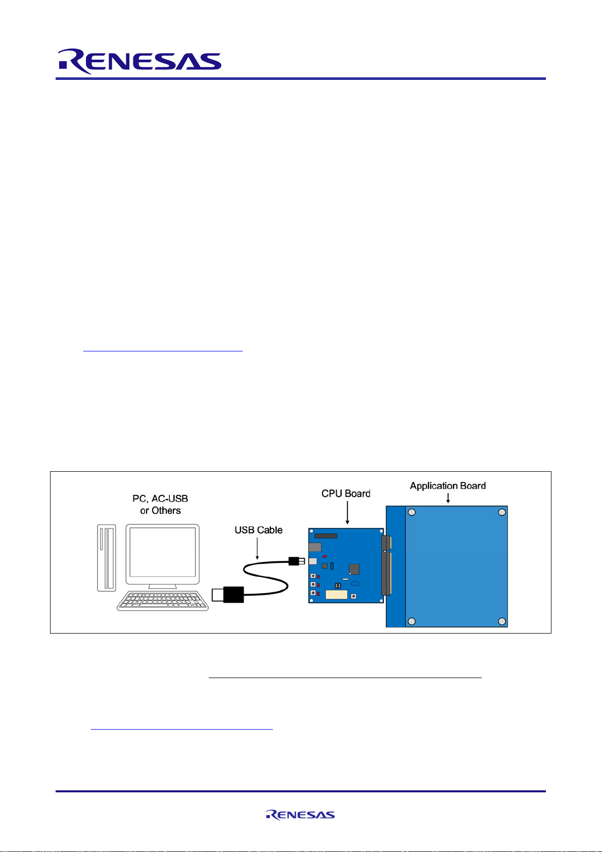
3.1 Connections
① Connect both CN1 and CN2 headers on the application board to the corresponding CN1 and CN2
connectors on the CPU board. Make sure both headers are inserted to match the direction and number
of pin numbers and the pins are fully inserted into the sockets.
② Insert the mini B plug end of the USB cable included in the kit into the CN6 pin on the CPU board, and
insert the opposite side of the cable into the USB port on the PC.
Figure3-1 System Connection Diagram
③ PC operation: The USB serial port driver is automatically installed the first time it is connected to the
PC (when using Windows7). Note: Do not remove the USB cable during driver installation.
After the driver auto-install is complete, download the driver that corresponds to your operating system
from the FTDI website below, and install it manually.
http://www.ftdichip.com/Drivers/VCP.htm
R12UZ0007EJ0100 Rev 1.00 Page 1 of 4
2016.02.17
Page 2
RX130 Group RX Capacitive Touch Evaluation System Quick Start Guide
④ CPU board operation: When the USB cable is connected, the CPU board automatically recognizes the
connected application board and starts the corresponding demo program. The demo program can be
identified by the LEDs on the CPU board.
LED1: Mutual-Capacitance Button / Proximity Sensor Board
LED2: Self-Capacitance Buttons / Wheels / Slider Board
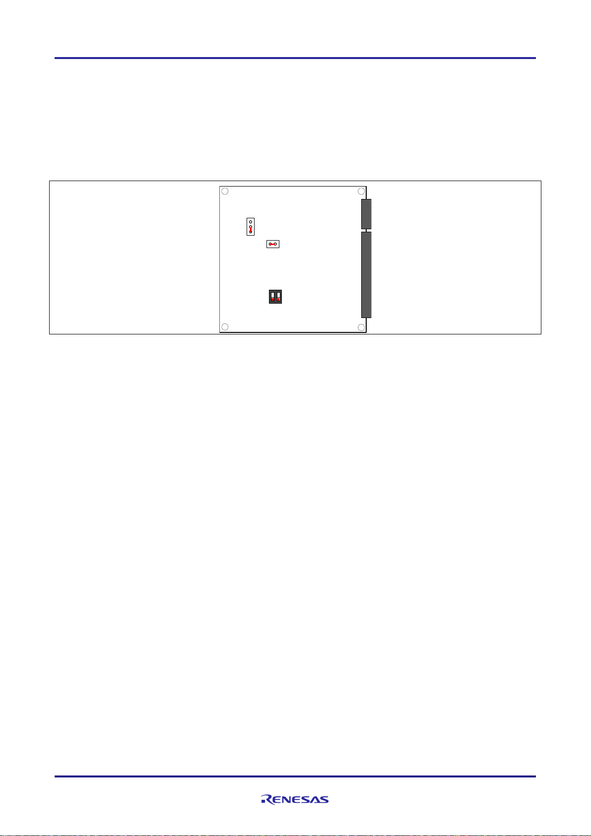
If the LEDs don’t illuminate in response to touch panel operations, make sure the switch and jumpers
on the CPU board are set as shown in Figure 3-2. After confirming the correct settings, press the reset
button (SW2) to restart operations and check the LEDs again.
JP1
JP2
ON
SW1
Figure 3-2 CPU Board Jumper/Switch Settings
3.2 Demo Program Operations
① Mutual-Capacitance Button / Proximity Sensor Board
Touch button input is enabled when the proximity sensor starts to respond.
After the USB cable is connected, the application board will illuminate the LEDs in sequence.
Please do not touch the application board during this initial adjustment of the touch sensors.
When initial adjustments are complete, all LEDs will turn off.
Moving a hand close to the surface of the application board will illuminate all LEDs, indicating touch
button input is enabled.
Each LED will turn on or turn off, accordingly, each time touch button input occurs.
If no touch button input occurs for a period of 5 seconds, all LEDs will turn off and touch button
input will be disabled.
② Self-Capacitance Buttons / Wheels / Slider Board
The LEDs indicate electrode touch positions.
After the USB cable is connected, various LEDs on the application board will turn on. This is part of
the touch sensor initial adjustment period−please do not touch the board at this time.
When initial adjustments are complete, all LEDs will turn off.
Moving a finger around the wheel (electrodes) will illuminate the associated LEDs.
Sliding a finger up and down the slider (electrodes) will illuminate the associated LEDs.
Pushing a button will illuminate the LED at the top of the button.
R12UZ0007EJ0100 Rev 1.00 Page 2 of 4
2016.02.17
Page 3

RX130 Group RX Capacitive Touch Evaluation System Quick Start Guide
3.3 Software Preparation
The following software is required to evaluate touch functions using Workbench6, the integrated
development environment (IDE) for capacitive touch. The Workbench6 installation package and the Visual
studio 2012 Run Time Library are available at the Renesas product website. Please obtain Microsoft .NET
framework4 from the Microsoft homepage if necessary. (Microsoft .NET framework4 may already be installed
in Windows7.)
1) Workbench6 installation package
2) Visual studio 2012Run Time Library (32-bit)
3) Microsoft .NET framework 4
In order to use the Workbench6 functions to auto-create source code, reflect parameter adjustment result
to the source code, and download the program to the MCU, you will need to obtain the Renesas CC-RX
compiler, the CS+ integrated development environment and other software, as well as the E1 emulator
debugger.
For more details, refer to the Workbench6 User’s Manual.
3.4 Software Installation
1) Install Workbench6
First, execute the Setup.msi downloaded from the product URL. This will start up the Workbench6
installer. Follow the instructions in the start-up window to complete the installation.
2) Install Run Timer Library
Next, install the Visual studio 2012 Run Time Library (32-bit). Note: even if you are using a 64-bit version
OS, please install the 32-bit Visual studio 2012 Run Time Library. The library is available at the following
URL.
http://www.microsoft.com/ja-jp/download/details.aspx?id=30679
3) Install .NET Framework
Finally, install Microsoft .NET framework 4 or later version, available at the following URL.
http://www.microsoft.com/ja-jp/download/details.aspx?id=17851
3.5 How to Start and Use Workbench6
The icon will appear on the PC desktop after Workbench6 is installed. Click the icon to start the
integrated development environment. The following window will appear when Workbench is launched.
Menu bar
Tool bar
Window area
Status bar
Figure3-3 Workbench6 Start-up Window
R12UZ0007EJ0100 Rev 1.00 Page 3 of 4
2016.02.17
Page 4

RX130 Group RX Capacitive Touch Evaluation System Quick Start Guide
Click Tuning Window to show the initial tuning window screen.
Figure3-4 Initial Screen of Tuning Window
From the tool bar, select Connection[Serial port connection]; when the Setup serial port window
opens, select COMxx:USB Serial Port(COMxx). (“xx” differs according to the user PC.) If USB Serial Port
does not appear, please confirm to make sure the driver is correctly installed and the boards and USB cables
are correctly connected. Select 38400 bps as the Baud rate. After the settings on both sides are complete,
click OK.
Next, under CapacitiveTouch, select [Start monitor]. This will allow you to confirm the touch position of
each key, the wheel, and the slider in real time. For more details on how to use these functions, please refer
to the Workbench6 manual.
Figure3-5 Board and Workbench6: from connection to measurement
4. Support
Online tech support and other information is available here: http://www.renesas.com/
You can also send technical inquiries to the following email addresses:
Japan site: csc@renesas.com
Global site: csc@renesas.com
© 2016 Renesas Electronics Europe Limited. All rights reserved.
© 2016 Renesas Electronics Corporation. All rights reserved.
© 2016 Renesas System Design Co., Ltd.
Website: http://www.renesas.com/
R12UZ0007EJ0100 Rev 1.00 Page 4 of 4
2016.02.17
 Loading...