

Page 1

APPLICATION NOTE
R20AN0451ES0130
Rev.1.30
Jan 25, 2019
RX Smart Configurator
User’s Guide: e² studio
Introduction
This application note describes the basic usage of the RX Smart Configurator (hereafter called the Smart Configurator),
which is an e² studio plug-in tool.
References to the e² studio integrated development environment in this application note apply to the followi ng ver sions.
• e² studio 7.3.0 and later
Target Devices and Compilers
Refer to the following URL for the range of supported devices and compilers:
https://www.renesas.com/smart-configurator
Contents
1. Overview .......................................................................................................................... 4
1.1 Purpose ......................................................................................................................................... 4
1.2 Features ........................................................................................................................................ 4
1.3 Software Components ................................................................................................................... 4
2. Creating a Project ............................................................................................................. 5
2.1 Create a project not using RTOS .................................................................................................. 5
2.2 Create a FreeRTOS project .......................................................................................................... 9
3. Operating the Smart Configurator ................................................................................... 16
3.1 Displaying the Smart Configurator Perspective .......................................................................... 16
3.2 Procedure for Operations ............................................................................................................ 17
3.3 File to be Saved as Project Information ...................................................................................... 18
3.4 Window ........................................................................................................................................ 19
3.4.1 Project Explorer..................................................................................................................... 20
3.4.2 Smart Configurator view ....................................................................................................... 20
3.4.3 MCU Package view ............................................................................................................... 21
3.4.4 Console view ......................................................................................................................... 22
3.4.5 Configuration Problems view ................................................................................................ 22
4. Setting of Peripheral Modules ......................................................................................... 23
4.1 Board Settings ............................................................................................................................. 23
4.2 Clock Settings ............................................................................................................................. 26
R20AN0451ES0130 Rev.1.30 Page 1 of 79
Jan 25, 2019
4.1.1 Selecting the device .............................................................................................................. 23
4.1.2 Selecting the board ............................................................................................................... 24
4.1.3 Exporting board settings ....................................................................................................... 25
4.1.4 Importing board settings ....................................................................................................... 25
Page 2

RX Smart Configurator User's Guide: e² studio
4.3 Component Settings .................................................................................................................... 27
4.3.1 Adding Code Generator components ................................................................................... 27
4.3.2 Downloading a FIT module ................................................................................................... 29
4.3.3 Adding FIT drivers or middleware ......................................................................................... 30
4.3.4 Download and import FIT sample project ............................................................................. 31
4.3.5 Switching between the component view and hardware view ............................................... 34
4.3.6 Removing a software component ......................................................................................... 35
4.3.7 Setting a CG driver ............................................................................................................... 36
4.3.8 Changing the resource for a CG configuration ..................................................................... 37
4.3.9 Setting a FIT Software Component....................................................................................... 40
4.3.10 Version change of FIT software component ......................................................................... 41
4.3.11 Setting the FreeRTOS Kernel ............................................................................................... 43
4.3.12 Configure general setting of component ............................................................................... 44
4.4 Pin Settings ................................................................................................................................. 45
4.4.1 Changing the pin assignment of a software component ....................................................... 46
4.4.2 Assigning pins using the MCU Package view ....................................................................... 47
4.4.3 Exporting pin settings ............................................................................................................ 48
4.4.4 Importing pin settings ............................................................................................................ 48
4.4.5 Pin setting using board pin configuration information ........................................................... 49
4.4.6 Pin filter feature ..................................................................................................................... 49
4.5 Interrupt Settings ......................................................................................................................... 50
4.5.1 Changing the interrupt priority level and fast interrupt setting .............................................. 51
4.5.2 Changing the interrupt vector number .................................................................................. 52
4.6 MCU migration feature ................................................................................................................ 53
5. Managing Conflicts ......................................................................................................... 56
5.1 Resource Conflicts ...................................................................................................................... 56
5.2 Resolving pin conflicts ................................................................................................................. 57
5.3 Missing Dependencies ................................................................................................................ 58
6. Generating Source Code ................................................................................................ 59
6.1 Outputting Generated Source Code ........................................................................................... 59
6.2 Configuration of Generated Files and File Names ...................................................................... 60
6.3 Initializing Clocks ......................................................................................................................... 63
6.4 Initializing Pins............................................................................................................................. 64
6.5 Initializing Interrupts .................................................................................................................... 67
6.6 Component Settings .................................................................................................................... 68
6.6.1 FIT module configuration ...................................................................................................... 68
6.6.2 FreeRTOS Kernel configuration............................................................................................ 70
7. Creating User Programs ................................................................................................. 71
7.1 Adding Custom Code in the Case of Firmware Integration Technology (FIT) ............................ 71
7.2 Adding Custom Code in the Case of Code Generator ................................................................ 72
8. Backing up Generated Source Code .............................................................................. 74
9. Generating Reports ........................................................................................................ 75
R20AN0451ES0130 Rev.1.30 Page 2 of 79
Jan 25, 2019
Page 3

RX Smart Configurator User's Guide: e² studio
9.1 Report on All Configurations (Text File) ...................................................................................... 75
9.2 Configuration of Pin Function List and Pin Number List (in csv Format) .................................... 76
9.3 Image of MCU Package (in png Format) .................................................................................... 76
10. Help ................................................................................................................................ 77
10.1 Help ............................................................................................................................................. 77
11. Documents for Reference ............................................................................................... 78
Website and Support ............................................................................................................. 79
R20AN0451ES0130 Rev.1.30 Page 3 of 79
Jan 25, 2019
Page 4

RX Smart Configurator User's Guide: e² studio
1. Overview
1.1 Purpose
This application note describes the basic usage of the Smart Configurator and the e² studio integrated development
environment, including the procedure for creating a project.
Refer to the User’s Manual of the e² studio for how to use the e² studio.
1.2 Features
The Smart Configurator is a utility for combining software to meet your needs. It handles the following three functions
to support the embedding of drivers from Renesas in your syste ms: importing middleware in the form of FIT (Firmware
Integration Technology) modules, generating driver code, and making pin settings.
1.3 Software Components
The Smart Configurator supports two types of software components: Code Generator (CG) and Firmware Integration
Technology (FIT). Drivers and middleware supported by each software type are:
• Basic drivers:
• CG drivers (CMT, A/D Converter, SCI, etc.)
• FIT modules (CMT, DTC, DMAC, RSPI, SCIFA, etc.)
• Middleware:
• FIT modules (USB, Ethernet, Flash Memory (programming the on-chip flash memory), etc.)
The basic driver is a control program for peripheral functions of microcomputer such as CMT, A/D converter, SCI, etc.
It is convenient to embed a software component (CG driver or FIT module) using code generation function.
In addition, FIT modules can be embedded for using middleware such as USB, Ethernet, and Flash memory
(programming the on-c hi p flash memory) as software components.
R20AN0451ES0130 Rev.1.30 Page 4 of 79
Jan 25, 2019
Page 5
RX Smart Configurator User's Guide: e² studio
2. Creating a Project
The following describes the procedure for creating a C project using the Smart Configurator.
Refer to the related documents on the e² studio for the details of the e ² studio project creation wizard.
2.1 Create a project not using RTOS
The following describes the procedure for creating a project not using RTOS.
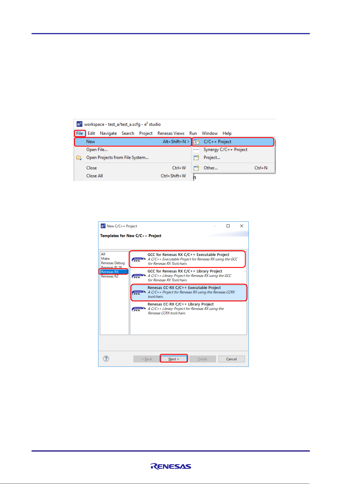
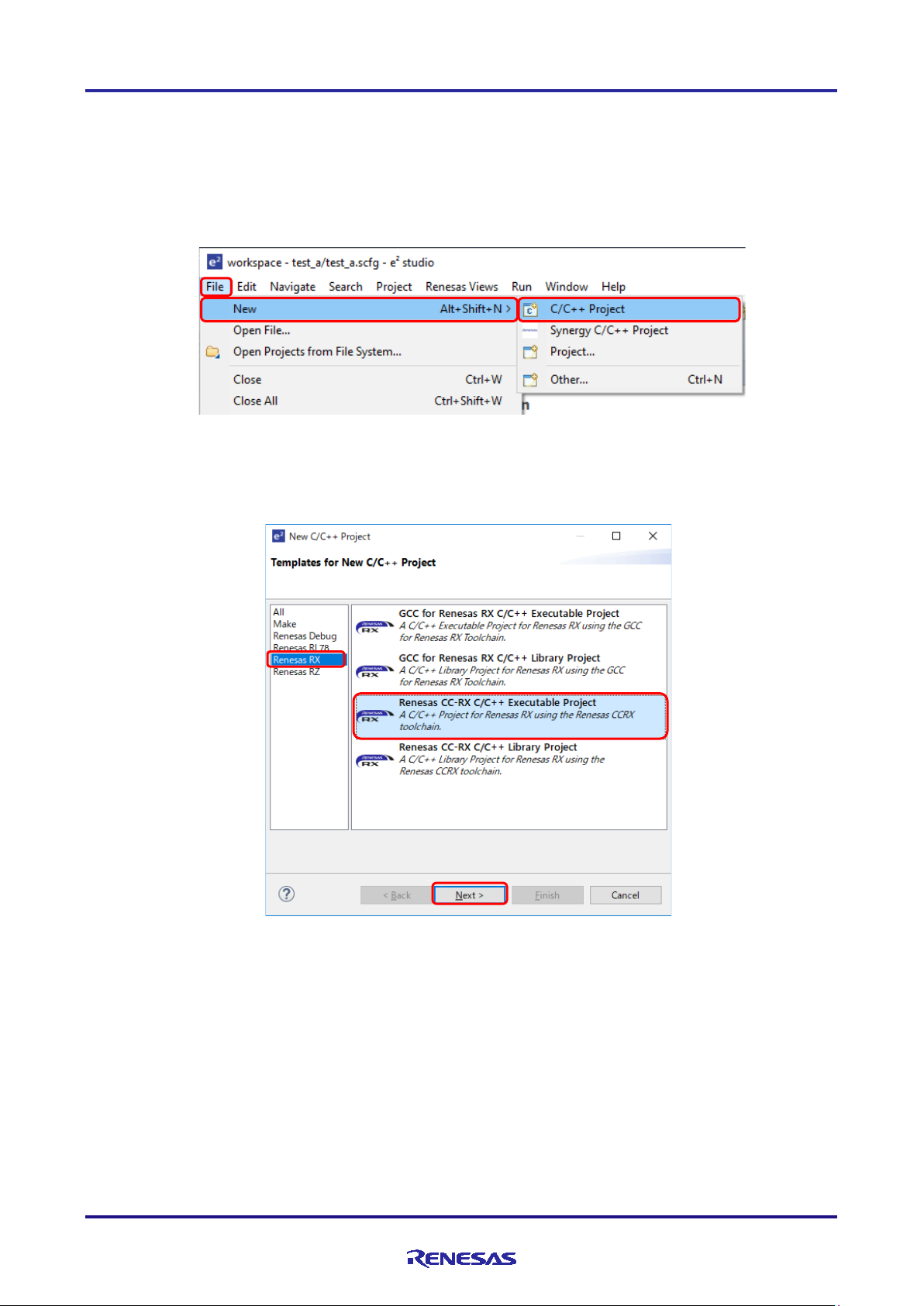
(1) Start e² studio and launch a workspace. After star ting, select [File] → [New] → [C/C++ Project] to activate the
project creation wizard.
Figure 2-1 Creating a New Project
(2) In the project creation wizard, select [Renesas RX] → [Renesas CC-RX C/C++ Executable Pr oj ect] or [GCC for
Renesas RX C/C++ Executable Project], and click on the [Next] button.
Figure 2-2 Templates for New C/C++ Project Dialog Box
R20AN0451ES0130 Rev.1.30 Page 5 of 79
Jan 25, 2019
Page 6
RX Smart Configurator User's Guide: e² studio
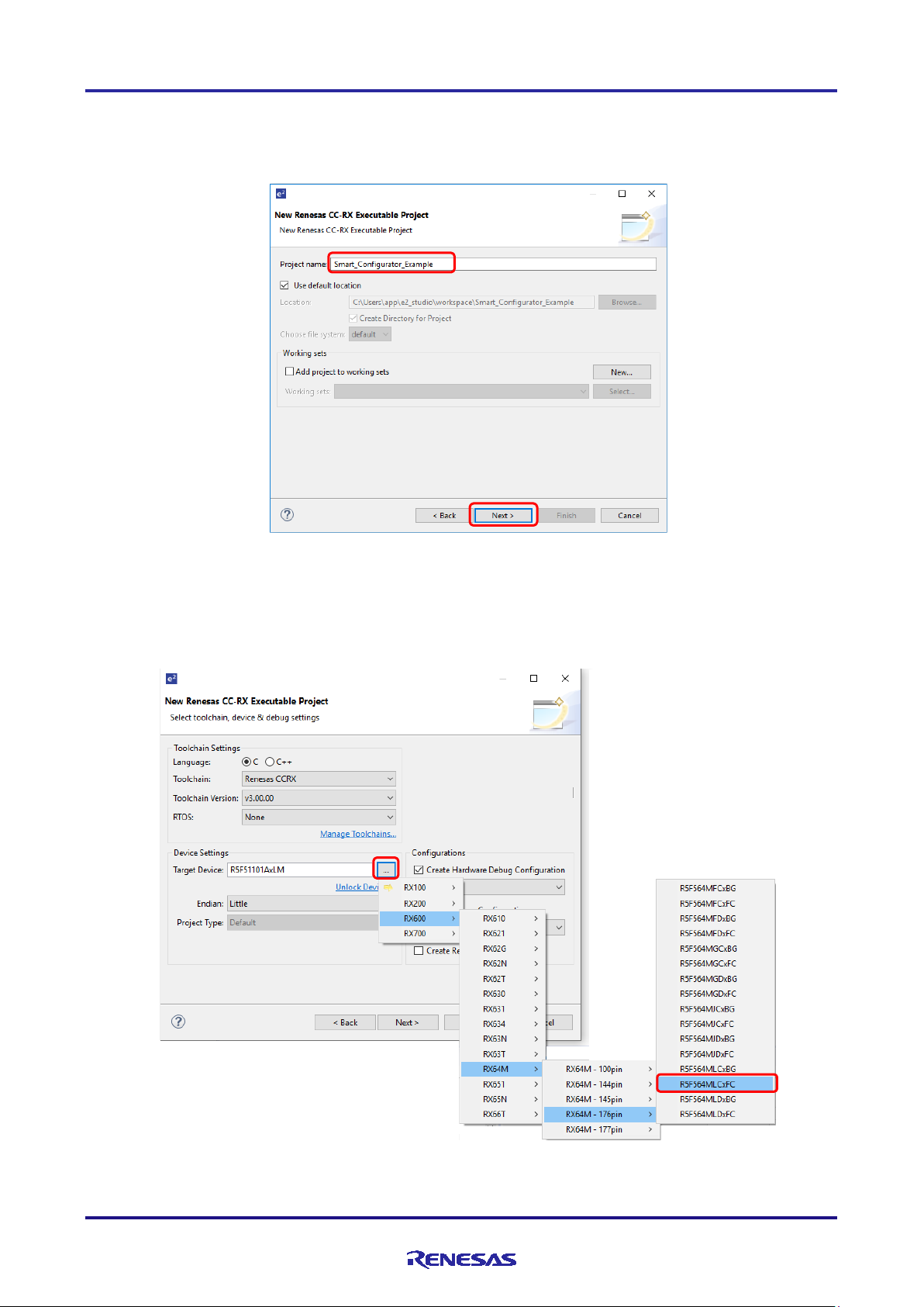
(3) Enter project information. Click on the [Next] button to continue.
(e.g. CC-RX executable project, Project name: "Smart_Configurator_Example")
Figure 2-3 Creating a New Renesas CC-RX Executable Project
(4) Select the toolchain, device, and debug configuration. Click on the [Next] button.
(e.g. Target Device: RX64M – 176 pins (Part number: R5F564MLCxFC))
Figure 2-4 Selecting the Toolchain, Device, and Debug Configuration
R20AN0451ES0130 Rev.1.30 Page 6 of 79
Jan 25, 2019
Page 7
RX Smart Configurator User's Guide: e² studio
(2)
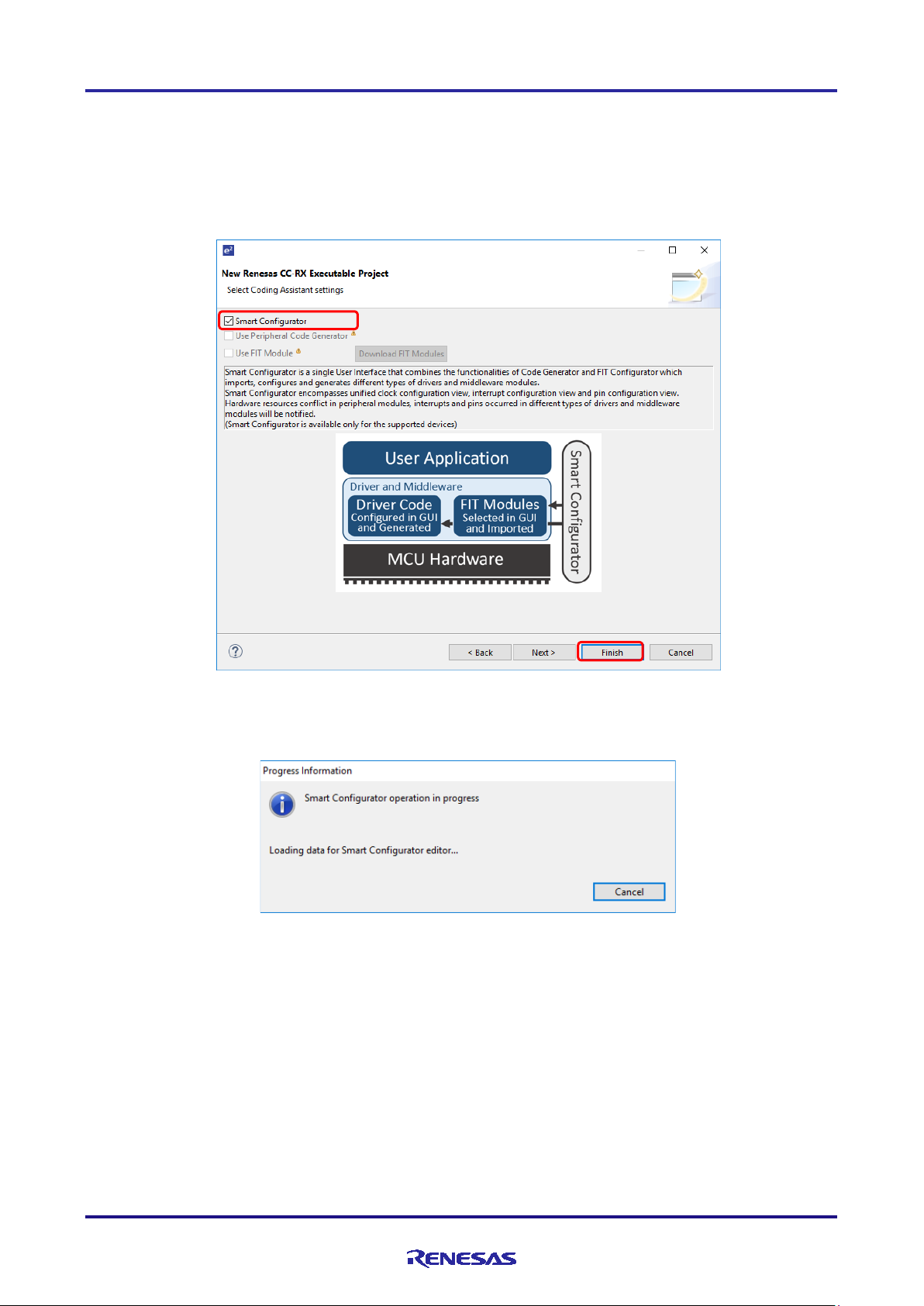
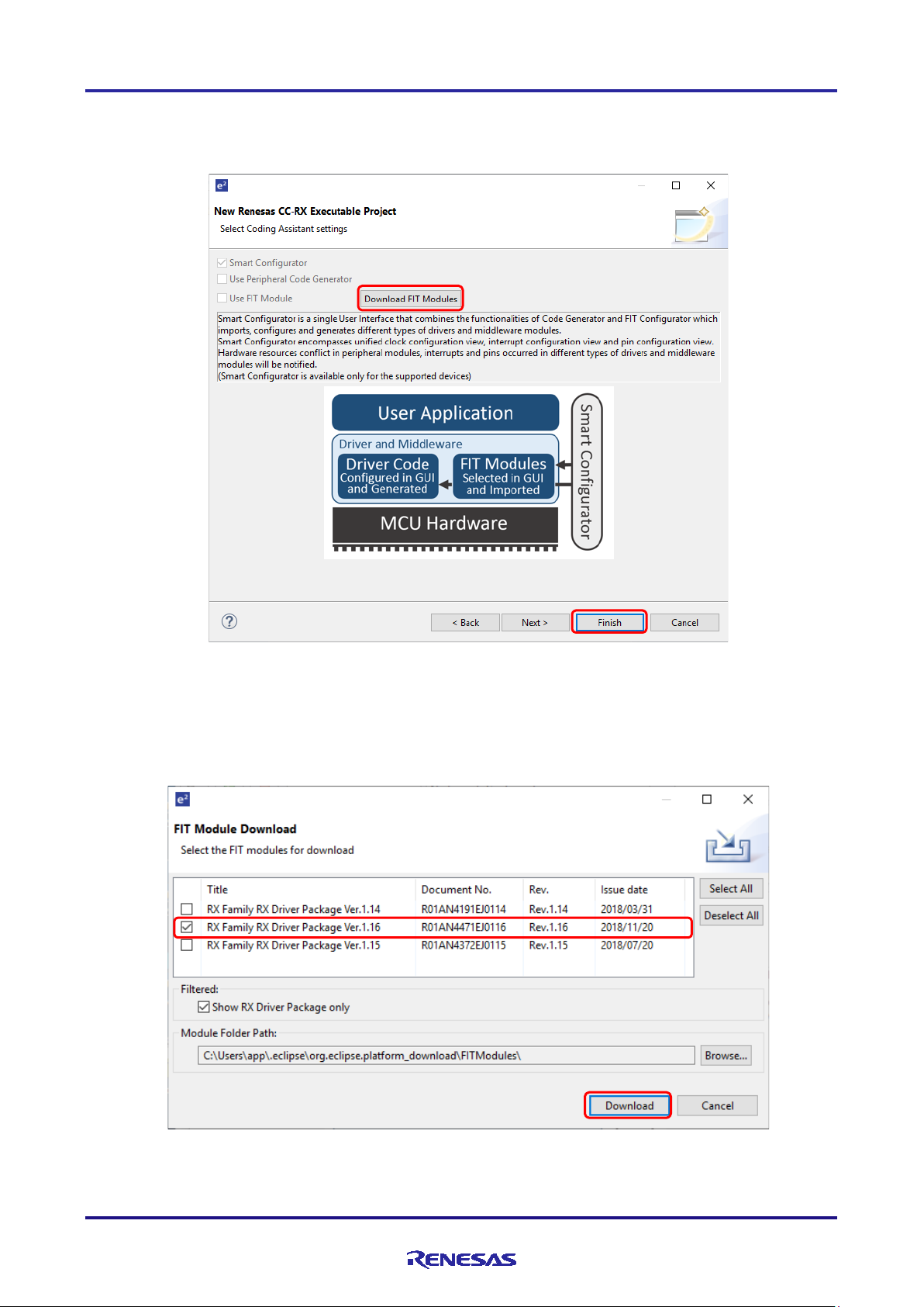
(5) In the [Select Coding Assistant settings] dialog box, select the [Smart Configurator] checkbox and click on the
[Finish] button.
Note: [Smart Configurator] checkbox is enable only if device supported by Smart Configurator is selected at
(4).
Figure 2-5 Selecting the Coding Assistant Tool
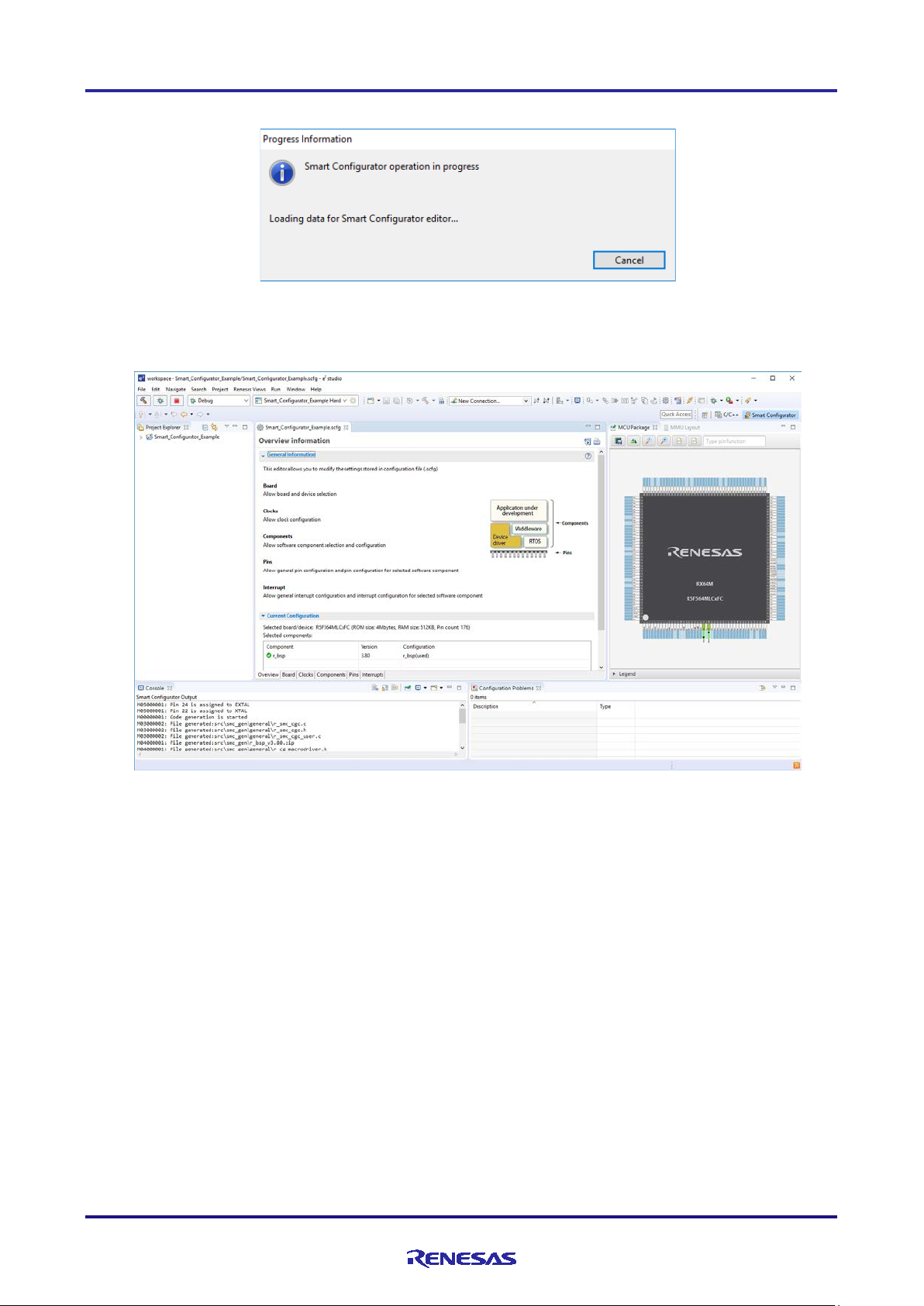
(6) Wait for completion of project creation.
Figure 2-6 Progress of Project creation
R20AN0451ES0130 Rev.1.30 Page 7 of 79
Jan 25, 2019
Page 8
RX Smart Configurator User's Guide: e² studio
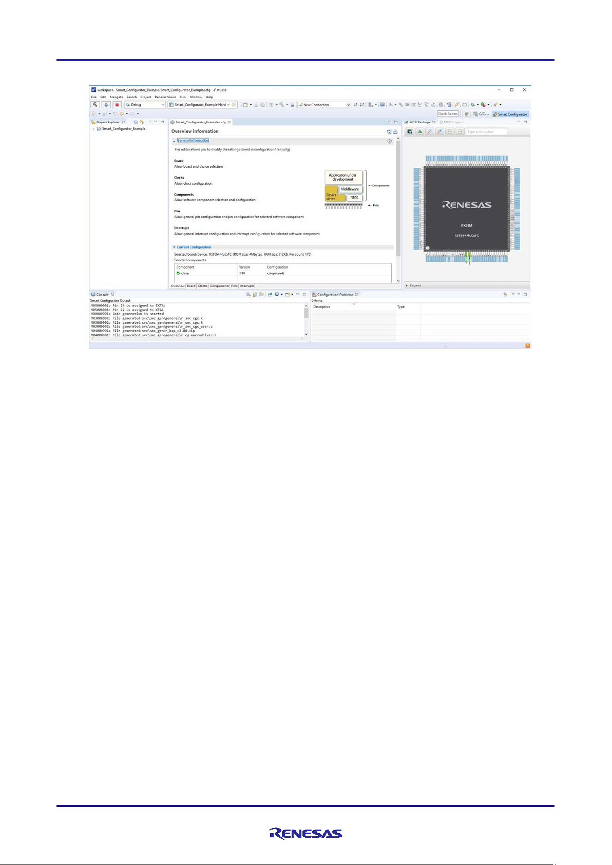
(7) After a new C Project is successfully created, the project will be opened in the Smart Configurator perspective.
Figure 2-7 Smart Configurator Perspective
R20AN0451ES0130 Rev.1.30 Page 8 of 79
Jan 25, 2019
Page 9
RX Smart Configurator User's Guide: e² studio
2.2 Create a FreeRTOS project
The following describes the procedure for creating a FreeRTOS project.
For FreeRTOS project supported devices and Renesas FreeRTOS, refer to Renesas FreeRTOS related documentation
("11 Documents for Reference").
(1) Start e² studio and launch a workspace. After star ting, select [File] → [New] → [C/C++ Project] to activate the
project creation wizard.
Figure 2-8 Creating a New Project
(2) In the project creation wizard, select [Renesas RX] → [Renesas CC-RX C/C++ Executable Pr oj ect] and click on
the [Next] b utton.
Figure 2-9 Templates for New C/C++ Project Dialog Box
R20AN0451ES0130 Rev.1.30 Page 9 of 79
Jan 25, 2019
Page 10
RX Smart Configurator User's Guide: e² studio
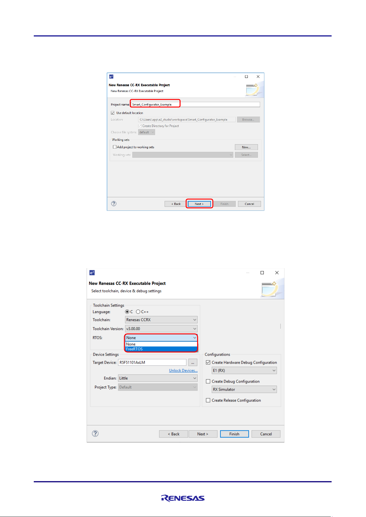
(3) Enter project information. Click on the [Next] button to continue.
(e.g. CC-RX executable project, Project name: "Smart_Configurator_Example")
Figure 2-10 Creating a New Renesas CC-RX Executable Project
(4) Select the toolchain and RTOS configuration. (e.g. RTOS: FreeRTOS)
If FreeRTOS has not been downloaded, go to procedure (5).
If FreeRTOS has been downloaded, go to procedure (7).
Figure 2-11 Selecting the Too l c hain and RTOS Configuration
R20AN0451ES0130 Rev.1.30 Page 10 of 79
Jan 25, 2019
Page 11
RX Smart Configurator User's Guide: e² studio
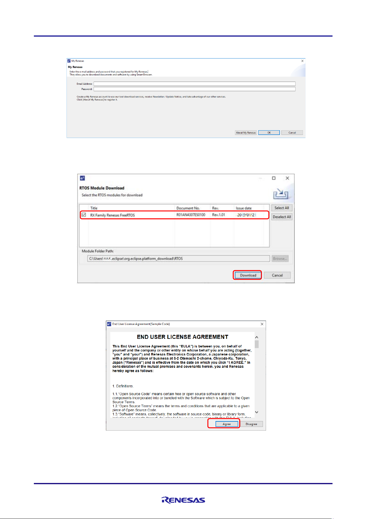
Note: Downloading requires login to "My Renesa s ". If you have not logged in, the following dialog box will prompt
you to log in. To register as a new user, click on the [About My Renesas] button.
Figure 2-12 Login to My Renesas
(5) In the [RTOS Module Download] dialog, select the FreeRTOS package and click [Download].
Figure 2-13 [RTOS Module Download] dialog
(6) When [End User License Agreement] dialog is displayed, click [ Agree].
Figure 2-14
[End User License Agreement] dialog
R20AN0451ES0130 Rev.1.30 Page 11 of 79
Jan 25, 2019
Page 12
RX Smart Configurator User's Guide: e² studio
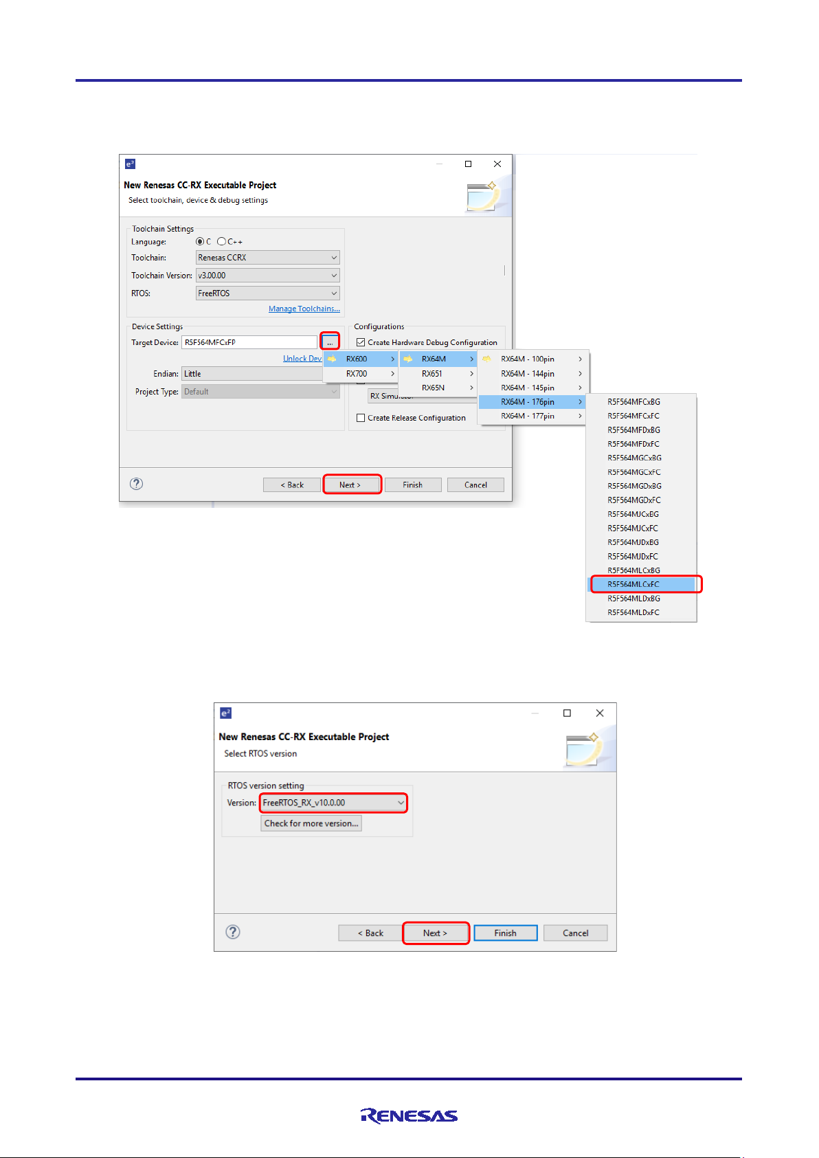
(7) Select the device and debug configuration. O nl y device supported by Renesas FreeRTOS can beselected. Click
on the [Next ] button
(e.g. Target Device: RX64M – 176 pins (Part number: R5F564MLCxFC))
Figure 2-15 Selecting the Device and Debug Configuration
(8) Select or Confirm the version and click [Next] button.
Figure 2-16 RTOS version confirmation
R20AN0451ES0130 Rev.1.30 Page 12 of 79
Jan 25, 2019
Page 13
RX Smart Configurator User's Guide: e² studio
(9) If the FIT module is not downloaded, click [Download FIT module] and go to procedure (10).
If the FIT module has already been downloaded, click [Finish] to complete the project creation. When the
creation of the project is completed, proceed to procedure (11).
Figure 2-17 Download FIT Modules
(10) Select the FIT module package and click [Download]. The [End User License Agreement] dialog will be
displayed as in procedure (6), so click [Agree] and execute the download. When the download is completed, you
will return to the [Select Coding Assi s tant settings] dialog in procedure (9), so please complete the project
creation by clicking [Finish].
Figure 2-18 [FIT Module Download] dialog
R20AN0451ES0130 Rev.1.30 Page 13 of 79
Jan 25, 2019
Page 14
RX Smart Configurator User's Guide: e² studio
(11) Wait for completion of project creation.
Figure 2-19 Progress of Project creation
(12) After a new C Project is successfully created, the project will be opened in the Smart Configurator perspective.
Figure 2-20 Smart Configurator Perspective
R20AN0451ES0130 Rev.1.30 Page 14 of 79
Jan 25, 2019
Page 15
RX Smart Configurator User's Guide: e² studio
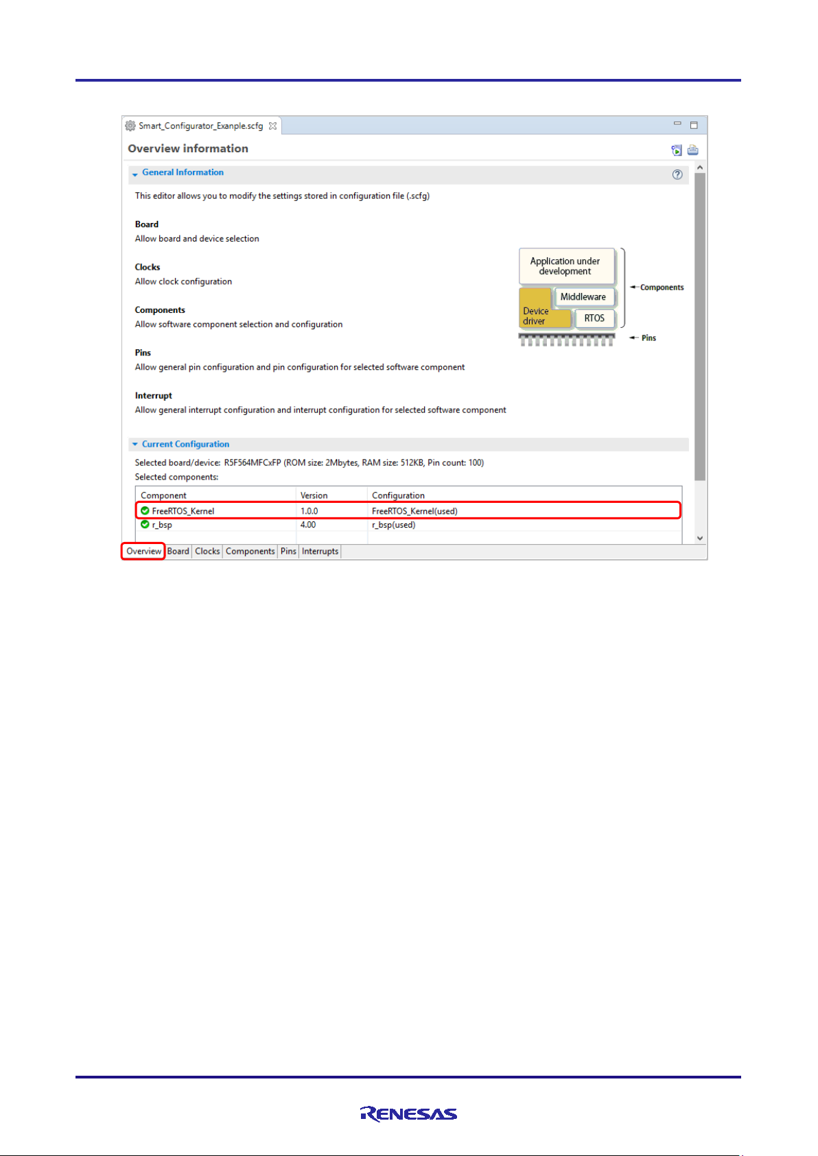
(13) The [RTOS Module Do wnload] dialog is displayed. Select the FreeRTOS package and click [Download].
Figure 2-21 Confirmation of configuration status of FreeRTOS package.
For the setting of FreeRTOS, refer to "4.3.11 Setting the FreeRTOS Kernel".
R20AN0451ES0130 Rev.1.30 Page 15 of 79
Jan 25, 2019
Page 16
RX Smart Configurator User's Guide: e² studio
3. Operating the Smart Configurator
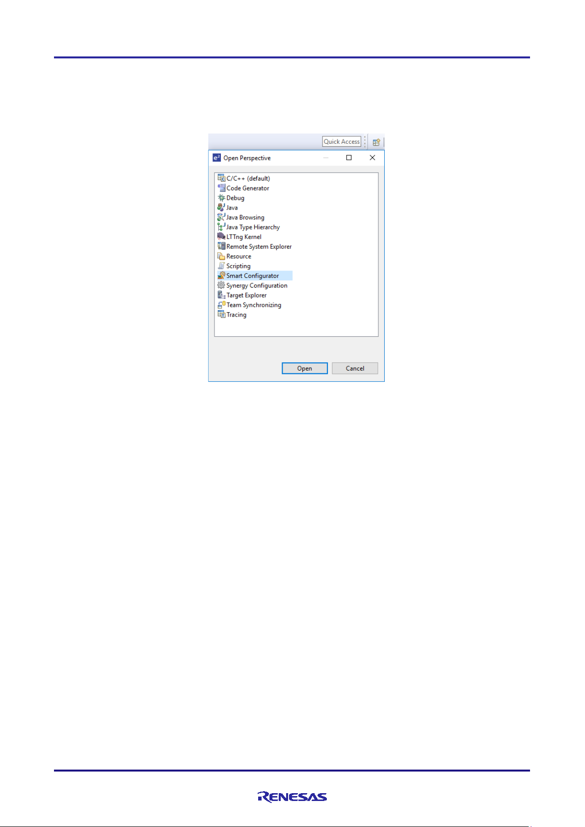
3.1 Displaying the Smart Configurator Perspective
To fully utilize Smart Configurator features, ensure that the Smart Configurator perspective is opened. If it is not
opened, select the perspective icon in the upper right corner of the e
2
studio window:
Figure 3-1 Opening the Smart Configurator Perspective
R20AN0451ES0130 Rev.1.30 Page 16 of 79
Jan 25, 2019
Page 17
RX Smart Configurator User's Guide: e² studio
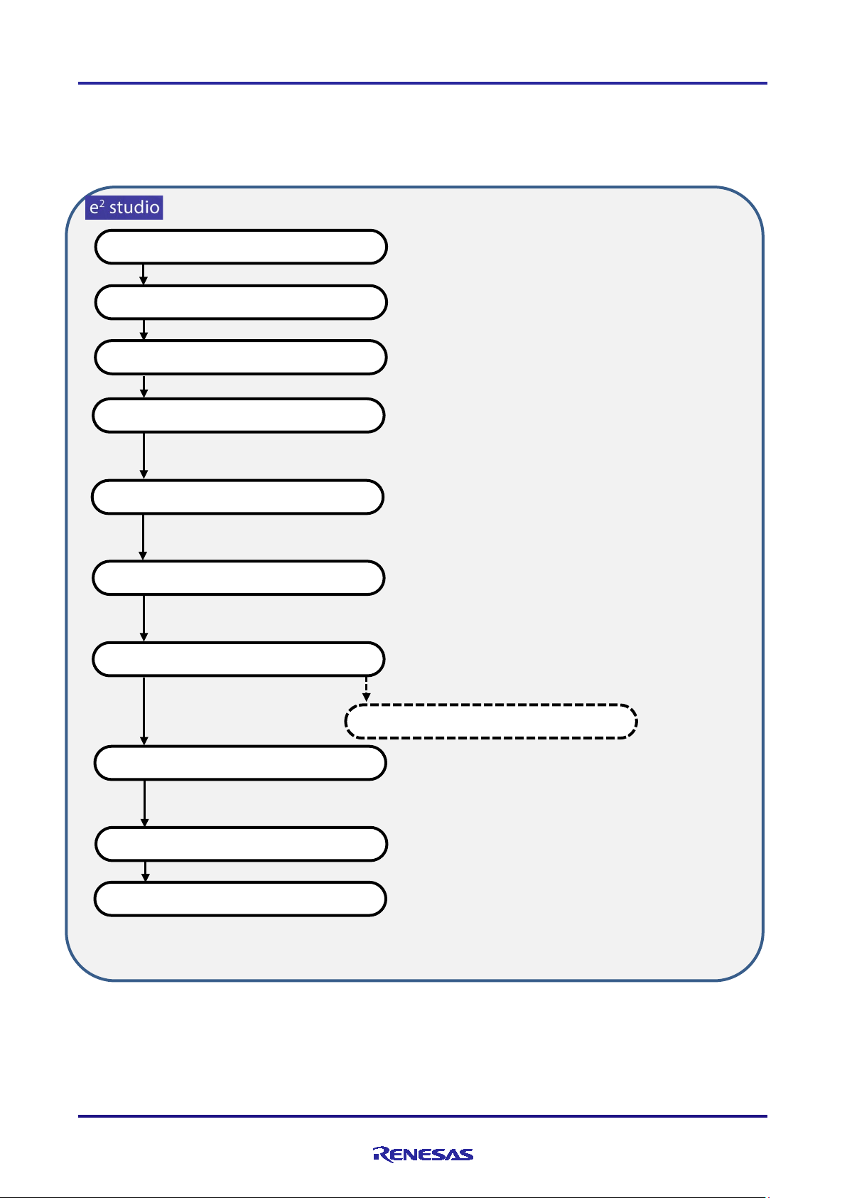
Operations in the e² studio
Starting the e² studio
Creating and loading an e² studio project
Displaying the Smart Configurator perspective
Setting of peripheral modules
Generating source code
Creating user programs
Building
Execution a nd debugging
Setting of pins
Refer to chapter 4, Setting of Peripheral
Modules.
Refer to section 4.4, Pin Settings.
Device information
Toolchain information
Generating reports
Refer to chapter 9, Generating Reports.
Setting of interrupts
Refer to section 4.5, Interrupt Settings.
Refer to chapter 6, Generating
Refer to chapter 7, Creating User
3.2 Procedure for Operations
Figure 3-2 shows the procedure for using the Smart Configurator to set up peripheral modules and build the project with
the e² studio. Refer to the related documents on the e² studio for the operation of the e² studio.
Source Code.
Programs.
Figure 3-2 Procedure for Operations
R20AN0451ES0130 Rev.1.30 Page 17 of 79
Jan 25, 2019
Page 18

RX Smart Configurator User's Guide: e² studio
3.3 File to be Saved as Project Information
The Smart Configurator saves the setting information such as the target MCU for the project, build tool, peripheral
modules, and pin functions in a project file (*.scfg), and refers to this information.
The project file from the Smart Configurator is saved in “project name.scfg”, which is at the same level as the project
file (.project) of the e² studio.
R20AN0451ES0130 Rev.1.30 Page 18 of 79
Jan 25, 2019
Page 19
RX Smart Configurator User's Guide: e² studio
(2)
(3)
(4)
(5)
(1)
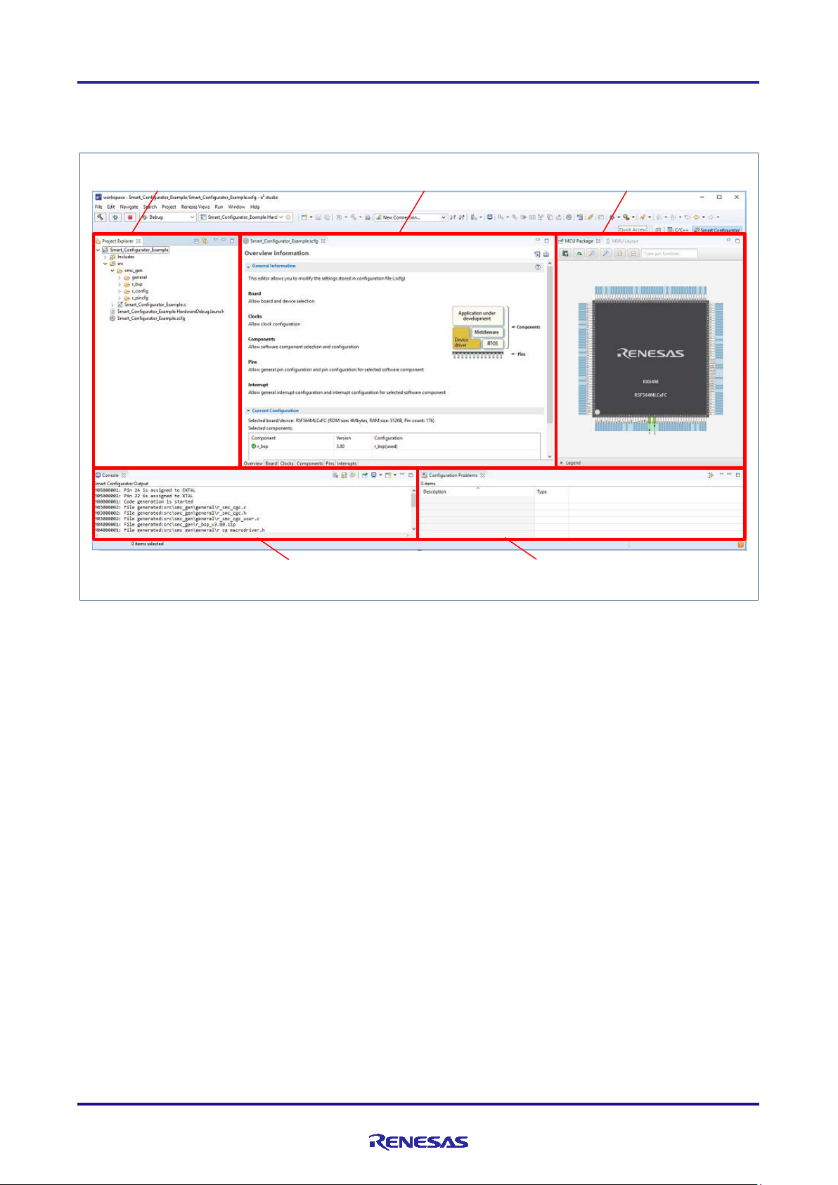
3.4 Window
The configuration of the Smart Configurator perspective is shown in Figure 3-3, Smart Config ura tor Perspective.
1) Project Explorer
2) Smart Configurator view
3) MCU Package view
4) Console view
5) Configuration Problems view
Figure 3-3 Smart Configurator Perspective
R20AN0451ES0130 Rev.1.30 Page 19 of 79
Jan 25, 2019
Page 20
RX Smart Configurator User's Guide: e² studio
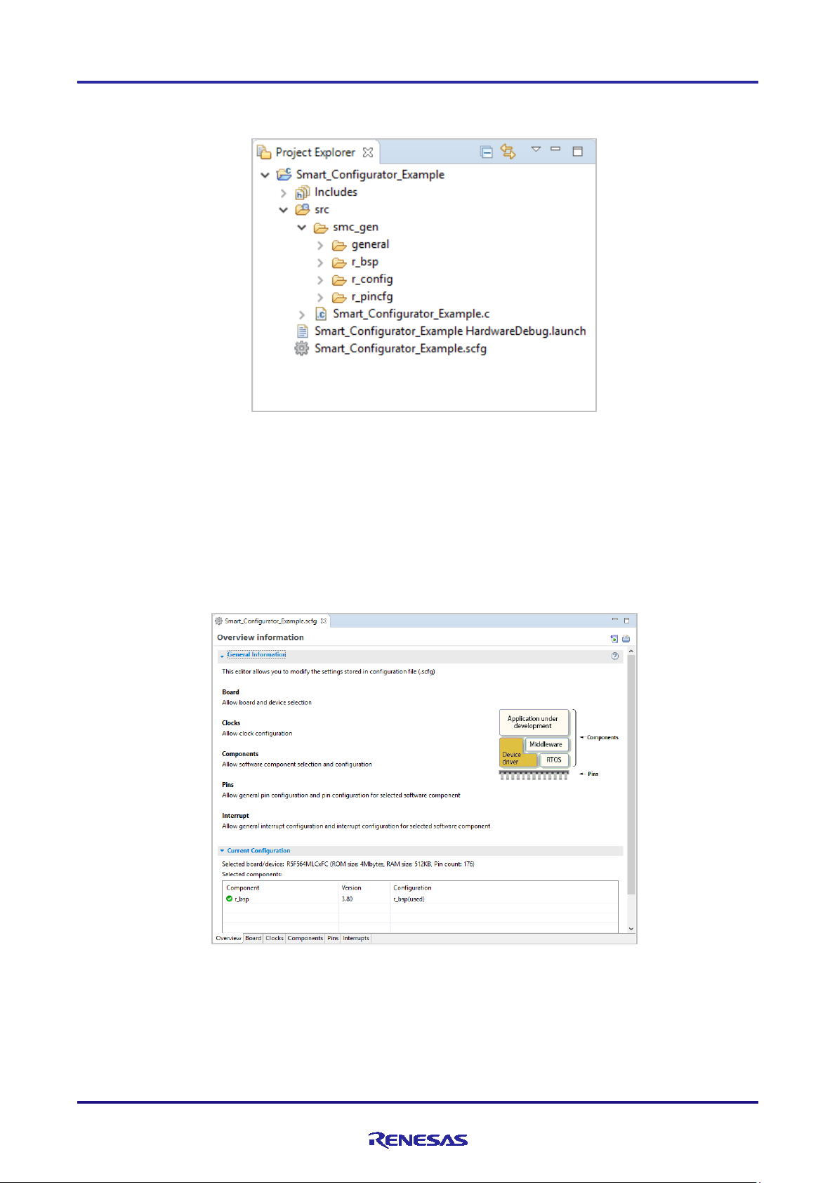
3.4.1 Project Explorer
The structure of the folders in the project is displayed in a tree form.
Figure 3-4 Project Explorer
When the Project Explorer is not opened, select [Window] → [Show View] → [Other] from the e
select [General] → [Project Explorer] on the opened [Show View] dialog box.
2
studio menu and
3.4.2 Smart C onfigurator view
The Smart Configurator view consists of six pages: [Overview], [Board], [Clocks], [Components], [Pins], and
[Interrupts]. Select a page by clicking on a tab; the displayed page will be changed.
Figure 3-5 Smart Configurator View
When this view is not op ened, right-click on the project file (*.scfg) in the Project Explorer and select [Open] from the
context menu.
R20AN0451ES0130 Rev.1.30 Page 20 of 79
Jan 25, 2019
Page 21
RX Smart Configurator User's Guide: e² studio
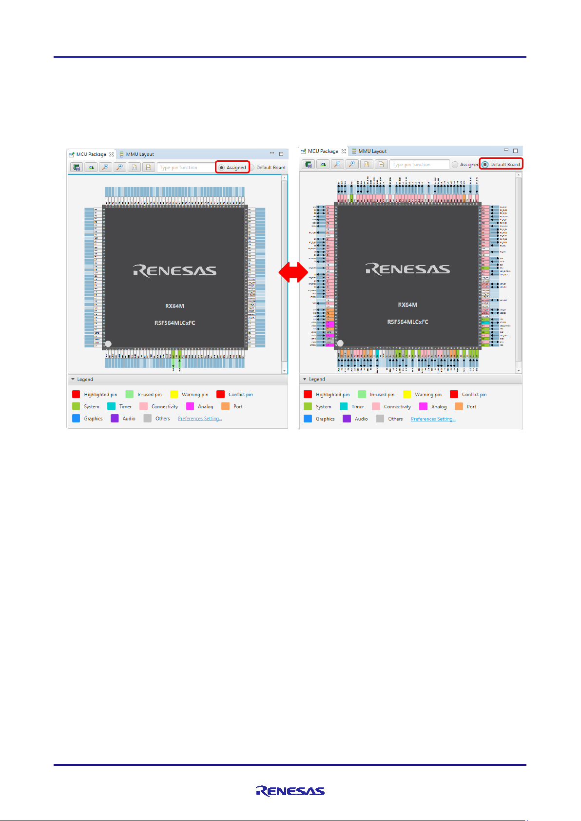
3.4.3 MCU Package view
The states of pins are displayed on the figure of the MCU package. The settings of pins can be modified from here.
Two types of package view can be switched between [Assigned] and [Default Board]. [Assigned] displays the
assignment sta t us of the pin setting, and [De fault Board] displays the initial pin setting information of the board. The
initial pin setting information of the board is the pin information of the board selected by [Board:] on the [Board] page
(refer to "4.1.2 Selecting the board").
Figure 3-6 MCU Package View
When this view is not opened, select [Renesas Views] → [Smart Configurator] → [MCU Package] from the e
menu.
2
studio
R20AN0451ES0130 Rev.1.30 Page 21 of 79
Jan 25, 2019
Page 22
RX Smart Configurator User's Guide: e² studio
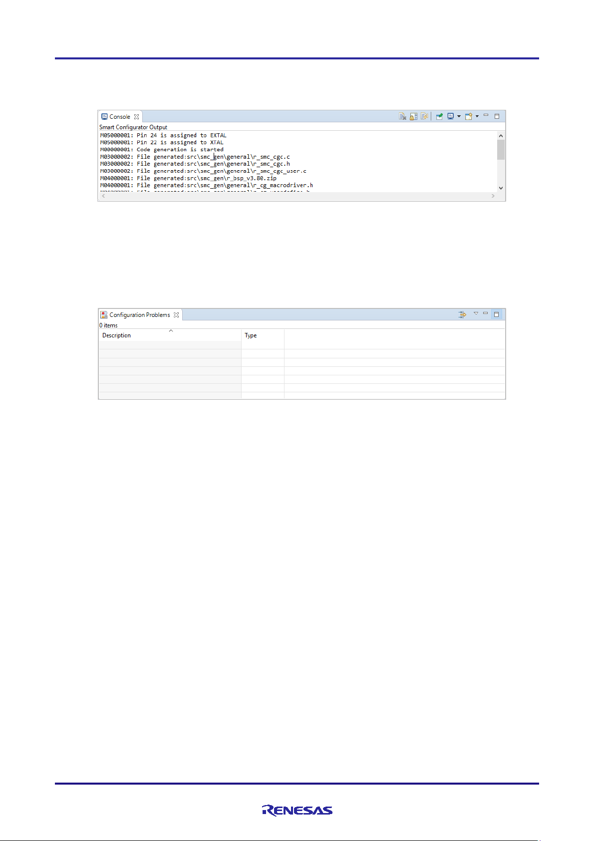
3.4.4 Console view
The Console view displays details of cha nges to the configuration made in the Smart Configurator or MCU Package
view.
Figure 3-7 Conso le View
2
When this view is not opened, select [Wind ow] → [Show View] → [Other] from the e
[General] → [Console] on the opened [Show View] dialog box.
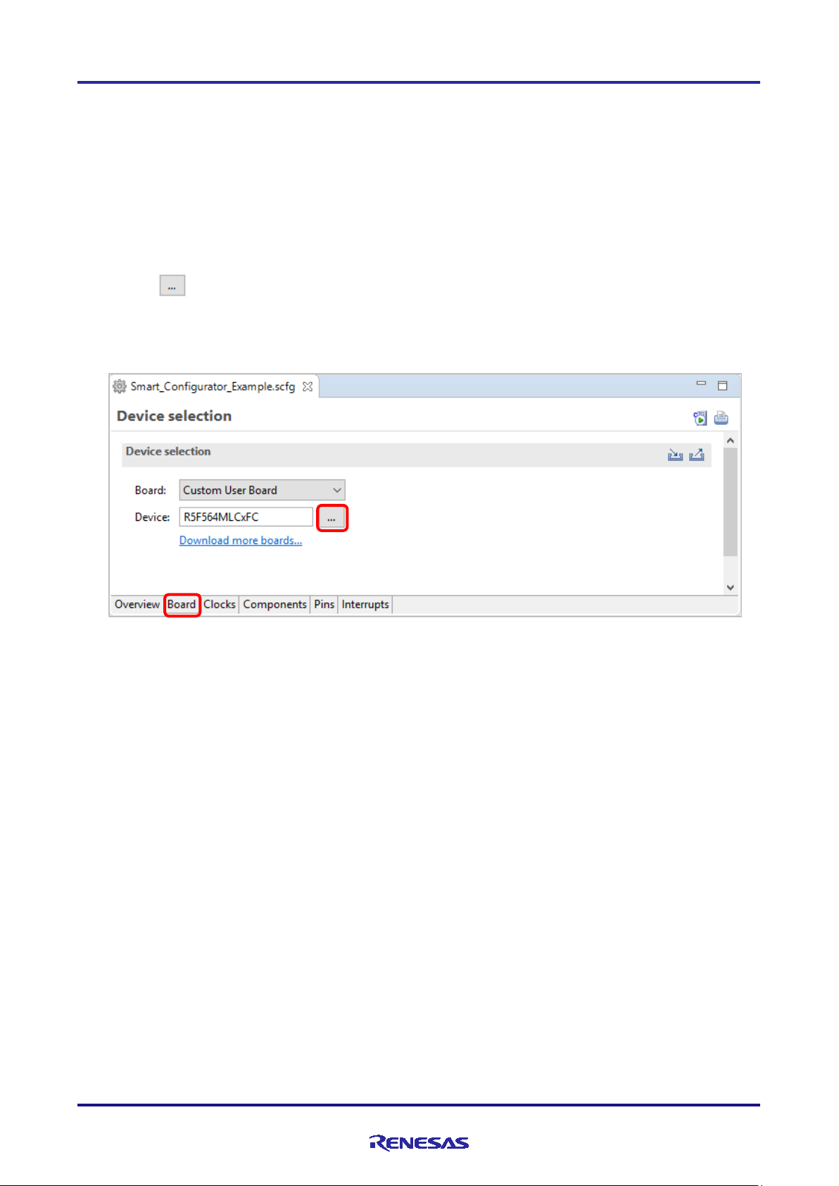
3.4.5 Configuration Problems view
The Configuration Problems view displays the details of conflicts between pins.
studio menu and select
Figure 3-8 Configuration Problems View
When this view is not op ened, select [Renesas Vie ws] → [Smart Configurator] → [Configuration Problems] from the e
studio menu.
2
R20AN0451ES0130 Rev.1.30 Page 22 of 79
Jan 25, 2019
Page 23
RX Smart Configurator User's Guide: e² studio
4. Setting of Peripheral Modules
You can select peripheral modules from the Smart Configurator view.
4.1 Board Settings
You can change the board and device on the [Board] tabbed page.
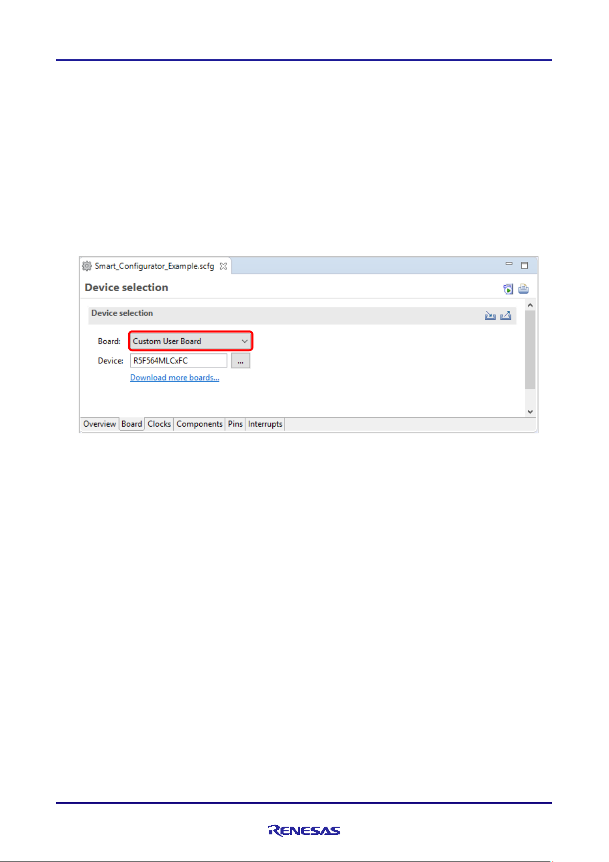
4.1.1 Selecting the device
Click on the [ ] button to select a device.
MCU migration function is recommended when changing the device. Follow the procedure of "4.6 MCU migration
function" to change the device.
Figure 4-1 Selecting the Device
Note: Device change is not reflected to the device of e
migration feature".
2
studio project. To change the device, perform from "4.6 MCU
R20AN0451ES0130 Rev.1.30 Page 23 of 79
Jan 25, 2019
Page 24
RX Smart Configurator User's Guide: e² studio
4.1.2 Selecting the board
By selecting a board, the following settings can be changed at one time.
• Pin assignment (Initial pin setting)
• Frequency of the main clock
• Frequency of the sub-clock
• Target device
The board setting information is defined in the Board Description File (.bdf).
The .bdf file of Renesas made board (e.g. Renesas Starter Kit) can be downloaded from website and imported.
In addition, by downloading the .bdf file provided by the alliance partner from website and importing it, it is possible to
select alliance part boards.
Figure 4-2 Selecting the Board
Note: Depending on the board selected, the device will change, Device change is not reflected to the target device of
2
studio project. If there is a change in the device, change the device suitable for that board from "4.6 MCU
e
migration feature".
R20AN0451ES0130 Rev.1.30 Page 24 of 79
Jan 25, 2019
Page 25
RX Smart Configurator User's Guide: e² studio
(2)
(1)
(1)
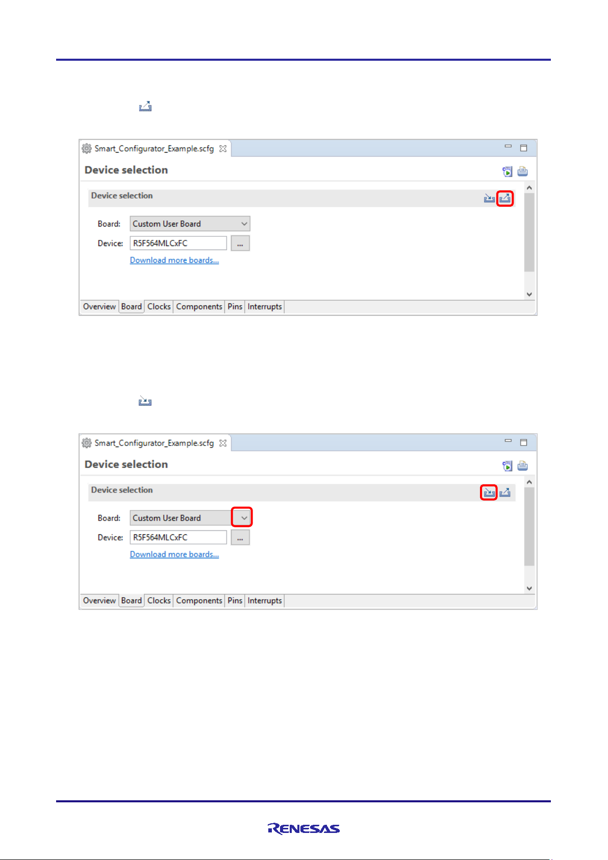
4.1.3 Exporting board settings
Follow the procedure below to export the board settings.
(1) Click on the [ (Export board setting)] button on the [Board] tabbed page.
(2) Select the output location and specify a name (Display Name) for the file to be exported.
Figure 4-3 Exporti ng Board Settings (bdf Fo rmat)
4.1.4 Importing board settings
Follow the procedure below to import board settings.
(1) Click on the [ (Import board setting)] button and select a desired bdf file.
(2) The board of the imported settings is added to the board selection menu.
Figure 4-4 Importing Board Settings (bdf Format)
Once a board setting file is imported, the added board is also displayed in the board selection menu of other projects for
the same device group.
R20AN0451ES0130 Rev.1.30 Page 25 of 79
Jan 25, 2019
Page 26

RX Smart Configurator User's Guide: e² studio
(5)
(3)
(6)
(4)
(2)
(1)
4.2 Clock Settings
You can set the system clock on the [Clocks] tabbed page. The settings made on the [Clocks] page are used for all
drivers and middleware.
Follow the procedure below to modify the clock settings.
(1) Specify the VCC voltage.
(2) Select the clocks required for device operations on the board (the main clock is selected by default).
(3) Specify the frequency of each clock in accordance with the board specifications (note that the frequency is fixed
for some internal clocks).
(4) When using the PLL circuit, select the clock source for the PLL.
(5) For the multiplexer symbol, select the cloc k source for t he output clocks.
(6) To obtain a desired output clock frequency, select a frequency division ratio from the drop-down list.
Figure 4-5 Clo c k Sett i ngs
R20AN0451ES0130 Rev.1.30 Page 26 of 79
Jan 25, 2019
Page 27
RX Smart Configurator User's Guide: e² studio
Components t ree
(1)
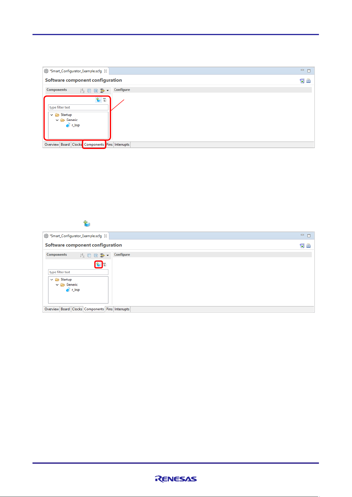
4.3 Component Settings
Drivers and middleware can be combined as software components on the [Components] page. Added components are
displayed in the Components tree at the left of the page.
Figure 4-6 [Components] Page
The Smart Configurator supports two types of software components: Code Generator (CG) components and Firmware
Integration Technology (FIT) modules.
4.3.1 Adding Code Generator components
The following describes the procedure for adding a component.
(1) Click on the [ (Add component)] icon.
Figure 4-7 Adding a Component
R20AN0451ES0130 Rev.1.30 Page 27 of 79
Jan 25, 2019
Page 28

RX Smart Configurator User's Guide: e² studio
(2)
(3)
(4)
(5)
(7)
(6)
(2) Select a component from the list in the [Software Component Selection] page of the [New Compone nt ] dia log
box (e.g. Single Scan Mode S12AD).
(3) Che ck that [Type] for the selected component is [Code Generator].
(4) Cli ck on [Next].
Figure 4-8 Adding a Code Generator Component
(5) Specify an appropriate configura t ion name in the [Add new configuration for selected component] page of the
[New Compone nt] dialog box or use the default name (e.g. Config_S12AD0).
(6) Select a hardware resource or use the default resource (e.g. S12AD0).
(7) Cli ck on [Finish].
Figure 4-9 Adding a Component
R20AN0451ES0130 Rev.1.30 Page 28 of 79
Jan 25, 2019
Page 29

RX Smart Configurator User's Guide: e² studio
(2)
4.3.2 Downloading a FIT module
You need to download a desired FIT driver or middleware from the Renesas Electronics website.
(1) Click on the [ (Add component)] icon.
(2) Clic k the [Download more software components] link in the [Software Component Selection] page of the [New
Component] dialog box to download a FIT module.
Figure 4-10 Downloading More Software Components
Note: Downloading requires login to "My Renesa s ". If you have not logged in, the following dialog box will prompt
you to log in. To register as a new use r, click on the [About My Renesas] button.
Figure 4-11 Login to My Renesas
R20AN0451ES0130 Rev.1.30 Page 29 of 79
Jan 25, 2019
Page 30

RX Smart Configurator User's Guide: e² studio
(3)
(5)
(4)
(2)
(3)
(4)
(3)
(3) Select the checkbox of the required module in the [FIT Module Download] dialog box. If [Show RX Driver
Package only] is unchecked, filtering of items is canceled.
(4) Cli ck on [Browse...] to select the location where the downloaded module is to be stored.
(5) Cli ck on [Download] to start downloading the selected FIT module.
Figure 4-12 Downloading a FIT Module
4.3.3 Adding FIT drivers or middleware
The following describes the procedure for adding FIT drivers or middleware.
(1) Click on the [ (Add component)] icon.
(2) Select components f rom the list in the [Software Component Selection] page of the [New Co mpo ne nt] dialog
box (e.g. r_ether_rx and r_qspi_smstr_rx). Two or more components can be selected by clicking with the Ctrl
key pressed.
(3) Che ck that [Type] for the selected co mponents is [FIT].
(4) Cli ck on [Finish].
Figure 4-13 Adding FIT Modules
R20AN0451ES0130 Rev.1.30 Page 30 of 79
Jan 25, 2019
Page 31
RX Smart Configurator User's Guide: e² studio
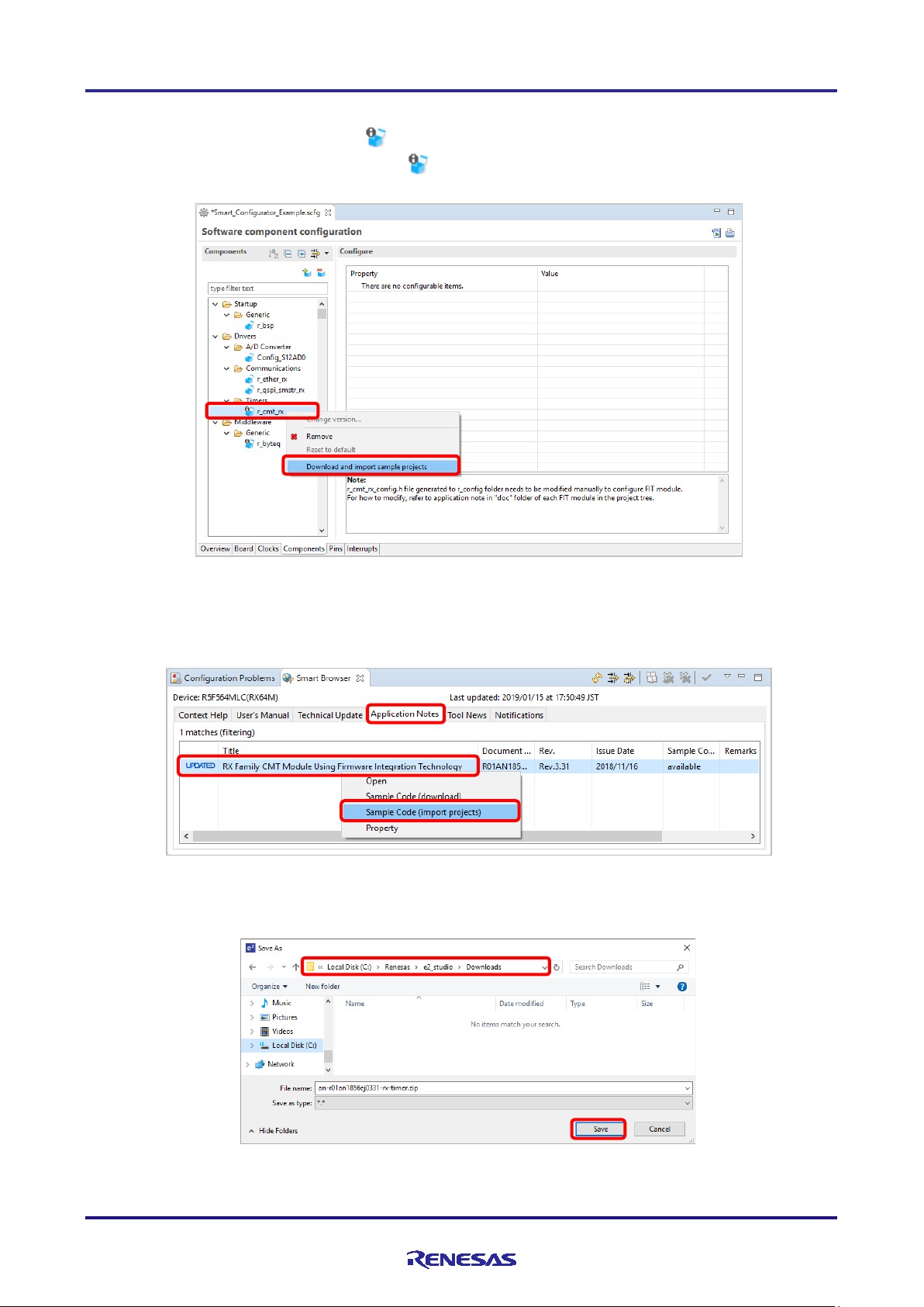
4.3.4 Download and import FIT sample project
When the FIT driver or middleware icon is [ ], you can download the sample project.
(1) Select the FIT driver or middleware of the [ ] icon and select [Download and import sample projects] from
the right menu. (e.g. CMT)
Figure 4-14 Downloa d and import sample projects
(2) The sample code is displayed on the [Application Notes] tab of the Smart Bro wser, so select [Sa mple Code
(import projects)] on the right menu.
Figure 4-15 Sample Code (import projects)
(3) Specify the save destination of the sample code and click [Save].
Figure 4-16 Sample code save destination
R20AN0451ES0130 Rev.1.30 Page 31 of 79
Jan 25, 2019
Page 32

RX Smart Configurator User's Guide: e² studio
(4) When [End User License Agreement] dialog is displayed, click [Agree].
Figure 4-17
(5) If the [Select import package] dialog is not displayed, go to procedure (6).
If the [Select import package] dialo g box is displayed, select the package to import and click [OK].
[End User License Agreement] dialog
Figure 4-18 [Select import package] dialog
(6) When the [Import] dialog of the project appears, select the project and click [Finish].
Figure 4-19 Import project
R20AN0451ES0130 Rev.1.30 Page 32 of 79
Jan 25, 2019
Page 33

RX Smart Configurator User's Guide: e² studio
(7) It is added to [Project Explorer] , and import of sample project is completed.
Figure 4-20 Addition to Project Explorer
R20AN0451ES0130 Rev.1.30 Page 33 of 79
Jan 25, 2019
Page 34

RX Smart Configurator User's Guide: e² studio
(1)
(2)
(3)
4.3.5 Switching between the component view and hardware view
The Smart Configurator also provides a function for adding a new compo nent by directly clicking a node in the
Components tree . To use this function, you need to switch the view of the Components tree from the component view to
the hardware view.
(1) Click on the [ (View Menu)] icon and select [Show by Hardware View]. The Components tree will display
the components in a hardware resource hierarchy.
Figure 4-21 Switching to the Hardware View
(2) Double-click on a hardware resource node (e.g. S12AD1 under 12-bit A/D converter) to open the [New
Component] dialog box.
(3) Select a component from the list (e.g. Single Scan Mode S12AD) to add a new configuration as described in
section 4.3.1.
Figure 4-22 Adding a CG Component to t he Hardware View
R20AN0451ES0130 Rev.1.30 Page 34 of 79
Jan 25, 2019
Page 35

RX Smart Configurator User's Guide: e² studio
(2)
(1)
4.3.6 Removing a software component
Follow the procedure below to remove a software component from a project.
(1) Select a software component from the Components tree.
(2) Click on the [ (Remove component)] icon.
Figure 4-23 Removing a Software Component
The selected software component will be removed from the Components tree.
2
Source files generated for this component are not removed from the e
by clicking [ (Generate Code)] icon, the source files generated for removed component will be removed from the e
studio project tree.
studio project tree. After generating source code
2
R20AN0451ES0130 Rev.1.30 Page 35 of 79
Jan 25, 2019
Page 36

RX Smart Configurator User's Guide: e² studio
(1)
(2) b.
(2) c.
(2) d.
(2) a.
4.3.7 Setting a CG driver
Follow the procedure below to set up a CG configuration.
(1) Select a CG configuration from the Components tree (e.g. Config_S12AD0).
(2) Configure the driver in the [ Configure] panel to the right of t he Components tree. The following steps and figure
show an example.
a. Select AN000.
b. Select [A/D conversion start trigger pin] under [Conversion start trigger setting].
c. Click on [Advance settin g] to expand the view.
d. Select [Discharge] for [Charge setting].
Figure 4-24 Setting of a CG Driver
Generation of a code in accordance with each CG configuration is enabled by default.
Right-clicking on a CG configurati on and then sele c ting the [ ] icon changes the icon to
[ ] and disables code generation for the CG configuration.
To enable code generation again, click on the [ ] icon and change it to [ ].
R20AN0451ES0130 Rev.1.30 Page 36 of 79
Jan 25, 2019
Page 37

RX Smart Configurator User's Guide: e² studio
(1)
(2)
(3)
(4)
4.3.8 Changing the resource for a CG configuration
The Smart Configurator enables you to change the resource for a CG configuration (e.g. from S12AD0 to S12AD1).
Compatible settings can be ported from the current resource to the new resource selected.
Follow the procedure below to change the resource for an existing software component.
(1) Right-click on a CG configur ation (e.g. Config_S12AD0).
(2) Select [Change resource] from the context menu.
Figure 4-25 Changing the Resource
(3) Select a new resource (e.g. S12AD1) in the [Resource Selection] dialog box.
(4) The [Next] button will be ac tive; click on it.
Figure 4-26 Components Page – Selecting a New Resource
R20AN0451ES0130 Rev.1.30 Page 37 of 79
Jan 25, 2019
Page 38

RX Smart Configurator User's Guide: e² studio
(6)
(8)
(7)
(5) Con figuration settings will be listed in the [Configuration setting selection] dialog box.
(6) Che ck the portability of the settings.
(7) Select whether to use the listed or default settings.
(8) Cli ck on [Finish].
Figure 4-27 Checking the Settings of the New Resource
The resource is automatically changed (e.g. changed from S12ADI0 to S12ADI1).
Figure 4-28 Resource Changed Automatically
To change the configuration name, follow the procedure below.
R20AN0451ES0130 Rev.1.30 Page 38 of 79
Jan 25, 2019
Page 39

RX Smart Configurator User's Guide: e² studio
(9)
(10)
(9) Right-click on the CG configuration.
(10) Select [Rename] to rename the configuration (e.g. change Config_S12AD0 to Config_S12AD1).
Figure 4-29 Re naming the Configuration
R20AN0451ES0130 Rev.1.30 Page 39 of 79
Jan 25, 2019
Page 40

RX Smart Configurator User's Guide: e² studio
4.3.9 Setti ng a FIT Software Component
To use FIT drivers or middleware, set configuration option. Setting methods are depends on components,
Set configuration options on configure panel
Set configuration options in configuration file for FIT module by manually
Configuration file for FIT module will be generated in the folder r_c onfig. For the settings of the configuration options,
refer to chapter 7.1, Adding Custom Code in the Case of Firmware Integration Technology (FIT).
In additio n, some compo nents have the configure panel for pin settin g, Followings are example of configure panel of
pin settings.
Figure 4-30 Pin Settings for r_ether_rx
Figure 4-31 Pin Settings for r_qspi_smstr_rx
R20AN0451ES0130 Rev.1.30 Page 40 of 79
Jan 25, 2019
Page 41

RX Smart Configurator User's Guide: e² studio
4.3.10 Version change of FIT software component
The following describes the procedure for version change of FIT software component.
(1) From the component tree, right-click the FIT software component whose version you want to change.
Figure 4-32 Version change of FIT software component
(2) Select [Change Versi on ...] from the context menu.
(3) I n the [Change Version] dialog box, select t he version you want to cha nge. If you select a version that the device
does not support, [Selected version doesn’t support current device or toolchain] will be displayed, so select the
corresponding version.
Figure 4-33 Select version of FIT software component
(4) Clic k [N e xt].
R20AN0451ES0130 Rev.1.30 Page 41 of 79
Jan 25, 2019
Page 42

RX Smart Configurator User's Guide: e² studio
(5) By versio n change, a list of setting items to be changed is displayed. Confirm that there is no problem and click
the [Finish].
Figure 4-34 Confirm setting change item
(6) As [Confirm to change version and proceed to generate code] Is displayed, if you do not have any problem, click
[Yes].
Figure 4-35 Confirm version change
(7) The FIT software component version is change and code generation is executed automatically.
R20AN0451ES0130 Rev.1.30 Page 42 of 79
Jan 25, 2019
Page 43
RX Smart Configurator User's Guide: e² studio
(1)
(2)
(3)
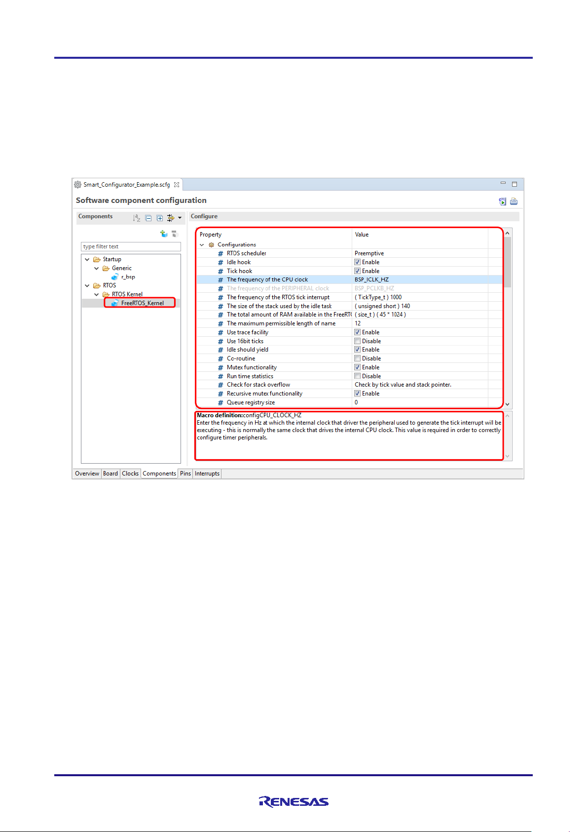
4.3.11 Setting the FreeRTOS Kernel
The following describes the procedure for setting the FreeRTOS Kernel.
For Renesas FreeRTOS, refer to Renesas FreeRTOS related documentation.
(1) Select [FreeRTOS_Kernel] in the component tree.
(2) Par ameters corresponding to the RTOS kernel are displayed in the [Configure] panel, and configuration settings
can be changed.
(3) Displays a description of the parameter selected in the [Configure] panel.
Figure 4-36 Settings for FreeRTOS_Kernel
R20AN0451ES0130 Rev.1.30 Page 43 of 79
Jan 25, 2019
Page 44

RX Smart Configurator User's Guide: e² studio
4.3.12 Configure general setting of component
You can change the general setting of the component suc h as location and dependency. If you want to change it, click
the [Configure general settings...] link on the [Software Component Selection] page displayed in the [New Component]
dialog (Figure 4-8), and display the [Preferences] dialog.
Figure 4-37 Configure general setting of component
Notes: 1. If the version of the module and its dependency do not match, a warning message W04020011 is
displayed. If you check the revision history of the module and its dependencies and you do not
need to change the module you are using, you can ignore this warning. To clear t his warn in g,
select "Do not check for dependent component" in the [Checking dependency] list box in
component preferences, then click [OK].
Figure 4-38 [Checking dependency] change
2. If you downloaded the FIT module directly from the website, unzip the downloaded zip file and copy
the xml file and zip file in the FIT Modules folder to the [Location settings] - [Location (RX)] folder.
To change the location, click [Browse…] and select another folder.
Figure 4-39 [Location (RX)] change
R20AN0451ES0130 Rev.1.30 Page 44 of 79
Jan 25, 2019
Page 45

RX Smart Configurator User's Guide: e² studio
Display switching
4.4 Pin Settings
The [Pins] page is used for assigning pin functions. You can switch the view by clicking on the [Pin Function] and [Pin
Number] tabs. The [Pin Function] list shows the pi n functions for each of the peripheral functions, and the [Pin
Number] list shows all pins in order of pin number.
Figure 4-40 [Pins] Page ([Pin Function])
When you select a board on the [Board] page, the initial pin setting information of the board is displayed in [Default
Function]. In addition, the [ ] icon displayed in the [Function] selection list indicates the initial pin function of the
board.
R20AN0451ES0130 Rev.1.30 Page 45 of 79
Jan 25, 2019
Figure 4-41 [Pins] Page ([Pin Number])
Page 46

RX Smart Configurator User's Guide: e² studio
(1)
(2)
(3)
(4)
(5)
4.4.1 Changing the pin assignment of a software component
The Smart Configurator assigns pins to the software components added to the project. Assignment of the pins can be
changed on the [Pins] page.
This page provides two lists: Pin Function and Pin Number.
Follow the procedure below to change the assignment of pins to a software component in the Pin Function list.
(1) Click on [ (Show by Hardware Resource or Software Components)] to switch to the component view.
(2) Select the target software component (e.g. Config_S12AD1).
(3) Click the [Enabled] header to sort by pins used.
(4) In the [Assignment] column or [Pin Number] column on the [Pin Func tion] list, change the pin assignment (e.g.
change from P17 to P13).
(5) In addition, assignment of a pin c an be changed by clicking on the [ (Next group of pins for the selected
resource)] button. Pin that has p e ripheral function is displayed each ti me the button is clicked.
Figure 4-42 Pin Settings – Assigning Pins on the [Pin Function] List
The Smart Configurator allows you to enable pin functions on the [Pins] page witho ut linking the current software
component to another. To distinguish these pins fro m other pins that are used by another software component, there will
be a remark "No component is using this pin" on the list.
Note:
The functio n fo r assigning pins is not available for some FIT modules.
For the method of assigning pins to such a FIT module, refer to the application note in the
<ProjectDir>¥src¥smc_gen¥r_xxx¥doc folder for the FIT module.
R20AN0451ES0130 Rev.1.30 Page 46 of 79
Jan 25, 2019
Page 47

RX Smart Configurator User's Guide: e² studio
(1)
(2)
(3)
(4)
4.4.2 Assigning pins using the MCU Package view
The Smart Configurator visualizes the pin assignment in the MCU Package view. You can save t he MCU Package view
as an image file, rotate it, and zoom in to and out fro m it.
Follow the procedure below to assign pins in the MCU Package view.
(1) Zoom in to the view by clicking the [ (Zoom in)] button or scrolling the view with the mouse wheel.
(2) Right-click on the target pin.
(3) Select the signal to be assigned to the pin.
(4) The color of the pins can be customized through [Preference Setting...].
Figure 4-43
R20AN0451ES0130 Rev.1.30 Page 47 of 79
Jan 25, 2019
Assigning Pins Using the MCU Package View
Page 48
RX Smart Configurator User's Guide: e² studio
(1)
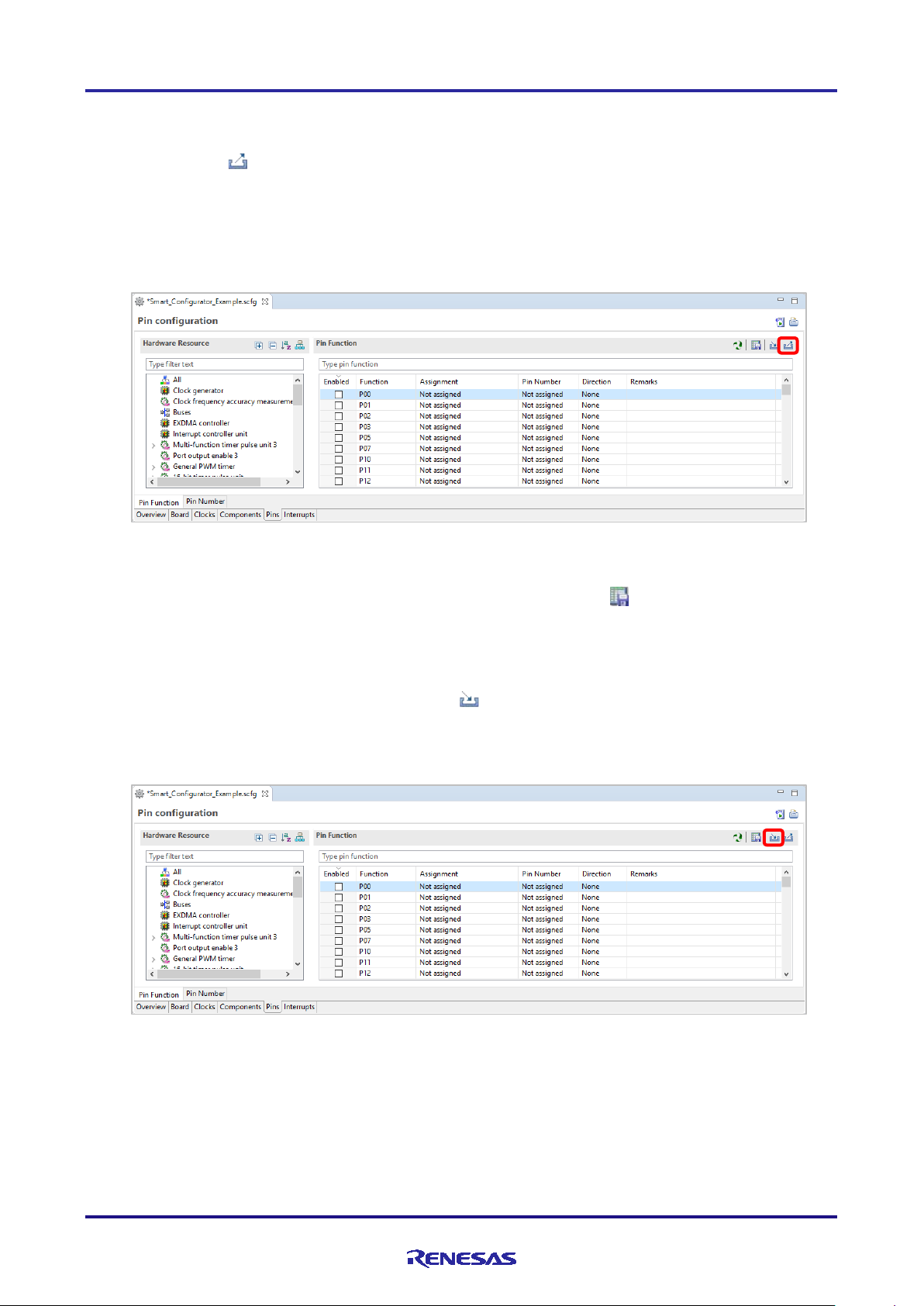
4.4.3 Exporting pin settings
The pin settings can be exported for later reference. Follow the procedure below to export the pin settings.
(1) Click on the [ (Export board setting)] button on the [Pins] page.
(2) Select the output location a nd specify a name for the file to be exported.
The exported XML file can be imported to another project having the same device part number.
Figure 4-44 Export i ng Pin Settings to an XML File
The Smart Configurator can also export the pin settings to a CSV file. Click on the [ (Save the list to .csv file)]
button on the [Pins] page.
4.4.4 Impor ting pi n settings
To import pin settings into the current project, click on the [ (Import board setting)] button and select the XML file
that contains the desired pin settings. After the settings specified in this file are imported to the project, the settings will
be reflected in the [Pin configuration] page.
Figure 4-45 Importing Pin Settings from an XML File
Note: The pin setting is reflected, but it is not reflected in the component setting.
R20AN0451ES0130 Rev.1.30 Page 48 of 79
Jan 25, 2019
Page 49

RX Smart Configurator User's Guide: e² studio
(1)
(2)
(3)
(4)
4.4.5 Pin setting using board pin configuration information
You can set t he initial pin configuration of the board at once. The following describes the procedure for collective
setting of pins.
(1) Select [Default Board] in the MCU Package. (The initial pin configuration of the board can be referred.)
(2) Open the [Pin Configuration] page and click the [Assign default board pins] button.
(3) When [Assign default board pins] dialo g o pens, click [Select all].
(4) Click [OK].
Figure 4-46 Setting for initial pin configurat ion
If you do not set pin settings all at once, specify them individually in procedure (3).
4.4.6 Pin filter feature
By specifying the filter range on the [Pin Function] tab and [Pin Number] tab on the [Pins] page, you can refer to it
more easily.
Figure 4-47 Filter for [Pin Function] tab
Figure 4-48 Filter for [Pin Number] tab
R20AN0451ES0130 Rev.1.30 Page 49 of 79
Jan 25, 2019
Page 50
RX Smart Configurator User's Guide: e² studio
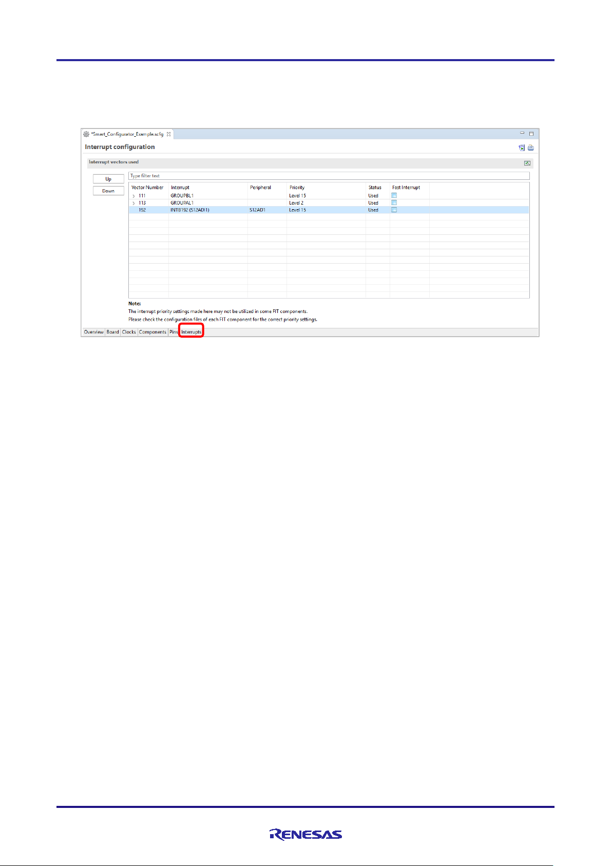
4.5 Interrupt Settings
Check and set the interrupts of the peripheral modules that have been selected on the [Components] page. T he interrupt s
are displayed for each of the vector numbers. Set the interrupt priority levels, the source of the fast interrupt, or a
dynamic interrupt vector number.
Figure 4-49 [Interrupts] Page
R20AN0451ES0130 Rev.1.30 Page 50 of 79
Jan 25, 2019
Page 51

RX Smart Configurator User's Guide: e² studio
(1)
(2)
(3)
4.5.1 Changing the interrupt priority level and fast interrupt setting
When an inter rupt is used in a CG configuratio n on the [Components] page, the stat us of the interrupt will be changed
to "Used". To display the used interrupts only, click on the [ (Show used interrupts)] button.
(1) You can change the interrup t priority level on the [Interrupts] page .
(2) To use an interrupt as a fast interrupt, tick the checkbox in the [Fast Interrupt] column. Only one inter rupt can be
specified as a fast interrupt among all interrupts and components used.
(3) Group interrupts are collapsed in the interrupt ta ble. Click on the [ (Open)] button to expand the view and see
the interrupts in the group interr upt list.
Figure 4-50 Interrupt Settings
Note:
The functio n for setting up interr upts is not available for the FIT modules.
For the method of setting up interrupts for each FIT module, refer to the application note in the
<ProjectDir>¥src¥smc_gen¥r_xxx¥doc folder for the FIT module.
R20AN0451ES0130 Rev.1.30 Page 51 of 79
Jan 25, 2019
Page 52

RX Smart Configurator User's Guide: e² studio
(1)
(2)
4.5.2 Changing the interrupt vector number
The [Interrupt configuration] page enables you to change the vector numbers of software configurable interrupts A and
B.
(1) Select a desired software configurable interrupt.
(2) The [Up] and [Down] buttons will be enabled. Click on a button to change the vector number.
Figure 4-51 Changing the Vector Number of Software Configurable Interrupt A or B
R20AN0451ES0130 Rev.1.30 Page 52 of 79
Jan 25, 2019
Page 53

RX Smart Configurator User's Guide: e² studio
4.6 MCU migration feature
The MCU migratio n feature helps to convert user project settings from device A to device B. Conversion of project
settings can be done within the same family and can be done from e2 studio project menu as follows.
Note: Project settings may change due to device change.
Back up the project before executing the device change.
(1) Select the project and choose [Change Device] from t he [Project] menu.
Figure 4-52 Select [Change Device]
(2) Select the target device from the device list and click "Next". (e.g. change to RX651)
Figure 4-53 Select target device
R20AN0451ES0130 Rev.1.30 Page 53 of 79
Jan 25, 2019
Page 54

RX Smart Configurator User's Guide: e² studio
Message
Explanation
Target device is not su pported by Sma r t
Displayed before changing to a device not supported by the
This change cannot be undone. Please make
sure you backup this project before continuing.
please execute it after backing up the project.
(3) Confirm the message displayed in [Discovered Issues] and click [Next].
Figure 4-54 Found problems
Configurator.
(4) Confirm items to be changed and click “Finish”.
Figure 4-55 Changes to be performed
Smart Configurator. You can’t convert Smart Configurator, but
you can convert Project, Builder, Linker, Debugger.
If you change the device, i t can’t be restored before change, so
R20AN0451ES0130 Rev.1.30 Page 54 of 79
Jan 25, 2019
Page 55
RX Smart Configurator User's Guide: e² studio
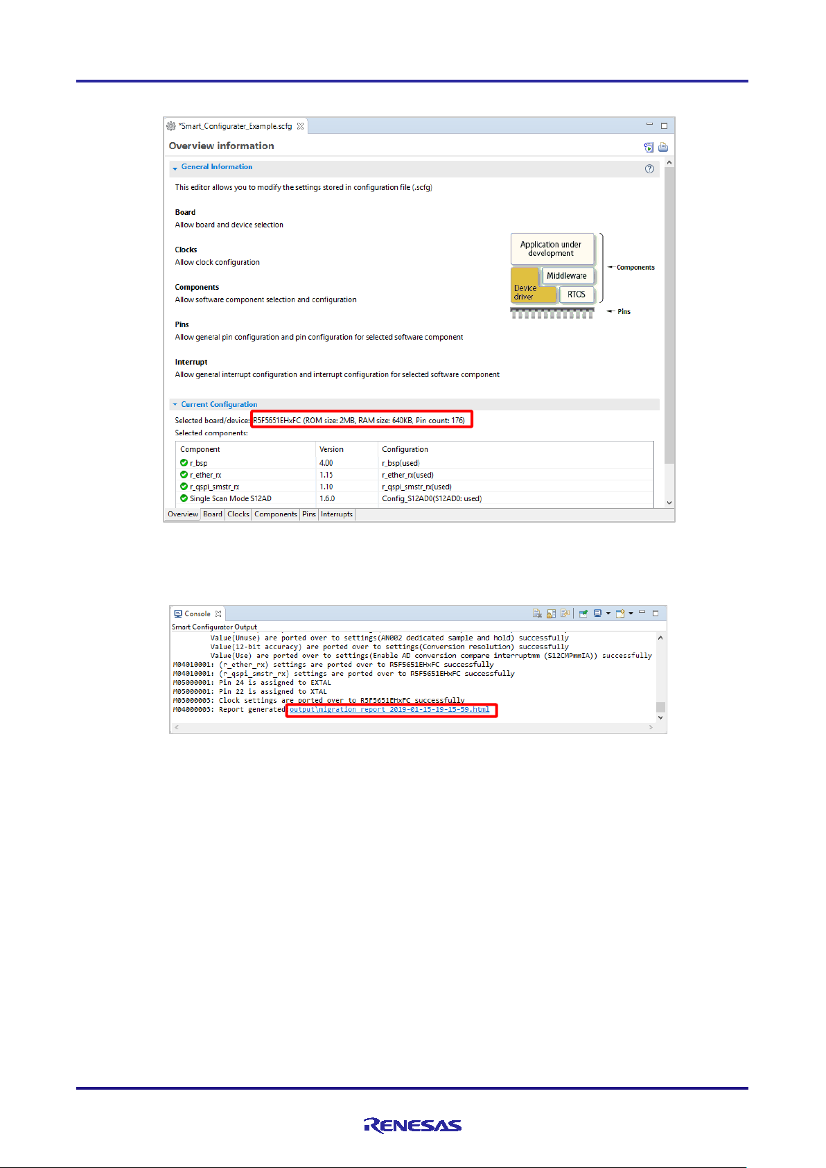
(5) The device name on the [Overview] page is updated.
Figure 4-56 Device Update Confirmation
(6) A report of the configurations' conversion stat us is generated out in the c onsole.
Figure 4-57 Configuration conversion status report
R20AN0451ES0130 Rev.1.30 Page 55 of 79
Jan 25, 2019
Page 56

RX Smart Configurator User's Guide: e² studio
5. Managing Conflicts
A user adding a component or configuring a pin or interrupt might cause problems in terms of resource conflict and
missing dependency modules. This information will be displayed in the Configuration Problems view. User can refer to
the displayed infor matio n to fix the conflict issues.
5.1 Resource Conflicts
When two software components are configured to use the same resource (e.g. S12AD1), an error mark ( ) will be
displayed in the Components tree.
The Configuration Problems view will display messages on peripheral conflicts to inform the user in which software
configurations peripheral conflicts have been detected.
Figure 5-1 Resource Conflicts
R20AN0451ES0130 Rev.1.30 Page 56 of 79
Jan 25, 2019
Page 57

RX Smart Configurator User's Guide: e² studio
5.2 Resolving pin conflicts
If there is a pin conflict, an error mark will appear on the tree and [Pin Function] list.
Figure 5-2 Pin Conflicts
The detailed information regarding conflicts is displayed in the Configuration Problems view.
Figure 5-3 Pin Conflict Messages
To resolve a conflict, right-click on the node with an error mark on the tree and select [Resolve conflict].
Figure 5-4 Resolving Pin Conflict s
The pins of the selected node will be re-assigned to other pins.
R20AN0451ES0130 Rev.1.30 Page 57 of 79
Jan 25, 2019
Page 58
RX Smart Configurator User's Guide: e² studio
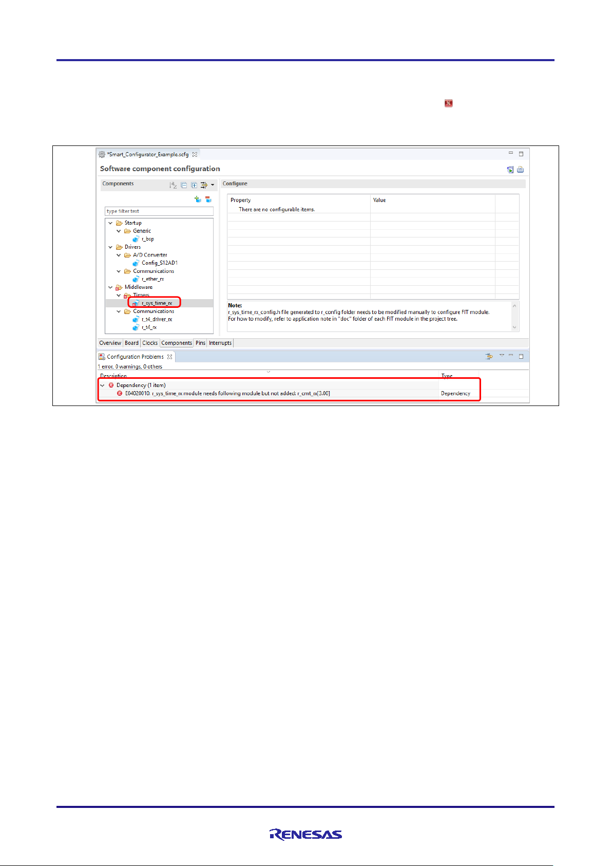
5.3 Missing Dependencies
When user adds a component which is dependent on other modules, the dependencies should also be added. For
example, when a user adds the FIT module named r_t4_driver_rx, an error message with the mark will be displayed
in the Configuration Problems view to inform the user that the dependent module r_cmt_rx is needed.
Figure 5-5 Error of Missing Dependency
To fix this error, add the dependent module r_cmt_rx into the project.
R20AN0451ES0130 Rev.1.30 Page 58 of 79
Jan 25, 2019
Page 59
RX Smart Configurator User's Guide: e² studio
6. Generating Source Code
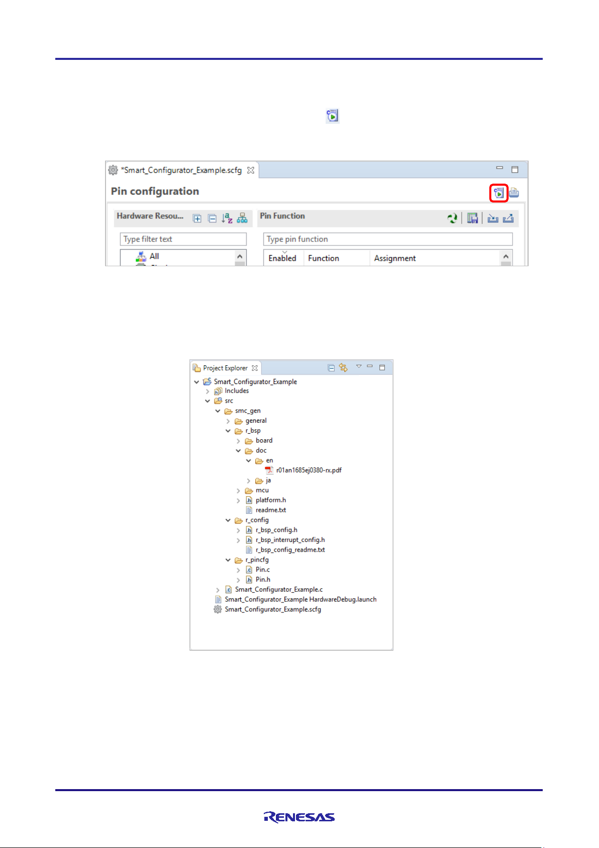
6.1 Outputting Generated Source C ode
Output a source file for the configured details by clicking on the [ (Generate Code)] button in the Smart
Configurator view.
Figure 6-1 Generating a Source File
The Smart Configurator generates a source file in <ProjectDir>¥src¥smc_gen and updates the source file list in the
Project Explorer. If the Smart Configurator has already generated a file, a backup copy of that file is also generated
(refer to chapter 8, Backing up Generated Source Code).
Figure 6-2 Source Files in the Project Explorer
R20AN0451ES0130 Rev.1.30 Page 59 of 79
Jan 25, 2019
Page 60

RX Smart Configurator User's Guide: e² studio
smc_gen
board
doc
mcu
platform.h
general
r_bsp
r_xxx
r_config
r_pincfg
“ConfigName”
doc
ref
src
r_xxx_if.h
r_bsp
r_bsp_
r_xxx
r_xxx
“ConfigName”.c
“ConfigName”_user.c
“ConfigName”.h
r_cg_xxx.h
r_cg_dmac
r_cg_hardware
r_cg_macrodriver.h
r_cg_userdefine.h
r_smc_cgc.c
r_smc_cgc.h
r_smc_cgc_user.c
r_smc_entry.h
r_smc_interrup.c
r_smc_interrupt.h
Pin.c
Pin.h
r_xxx_pinset.c
r_xxx_pinset.h
r_ pinset.h
r_cg_gpt
6.2 Configuration of Generated Files and File Names
Figure 5-3, Configuration of Generated Files and File Names, shows the folders and files output by the Smart
Configurator. Function main() is included in
e² studio.
r_xxx indicates the names of FIT modules, “ConfigName” indicates the name of the configuration formed by the
component set ti ng s, and “Project name” indicates a project name set in the e² studio.
_user.c
_user.c
{Project name}.c, which is generat ed when the project is created by the
_config.h
_interrupt
_config.h
_setup.c
_config.h
_pin_config.h
R20AN0451ES0130 Rev.1.30 Page 60 of 79
Jan 25, 2019
Figure 6-3 Configuration of Generated Files and File Names
Page 61

RX Smart Configurator User's Guide: e² studio
Folder
File
Description
general
This folder is always generated.
drivers of the same peripheral function.
r_cg_xxx.h
(Note*1)
These files are always generated.
r_cg_dmac_user.c
This file is always generated for a device with a DMAC function.
specifications).
r_cg_gpt_user.c
This file is always generated for a device with a GPT function.
r_cg_hardware_setup.c
This file is always generated.
than the clock source, fast interrupt, and group interrup ts.
r_cg_macrodriver.h
This file is always generated.
drivers.
r_cg_userdefine.h
This file is always generated.
User can add macro definitions in the dedicated user code areas.
r_smc_cgc.c
This file is always generated.
r_smc_cgc.h
This file is always generated.
than the selected clock source.
r_smc_cgc_user.c
This file contains functions to be added to R_CGC_Create.
r_smc_entry.h
This file is always generated.
including this file is necessar y.
r_smc_interrupt.c
This file is always generated.
r_smc_interrupt.h
This file is always generated.
definitions in application codes.
r_bsp
This folder is always generated.
It contains header files and source files commonly used by CG
The files contain macro definitions for setting SFR registers.
It contains interrupt service routines and callback functions shared
among some DMAC channels (d epending on the hardware
It contains interrupt service routines and callback functions shared
among some GPT channels (depending on the hardware
specifications).
It contains R_Systeminit that ca lls all driver initialization functio ns
with the name R_ConfigName_Create.
R_Systeminit also calls the functions for initializing clocks other
This header file contains common macro definitions used in
It contains the initialization of clock sources other than the clock
source selected in the [Clocks] page.
This header file contains macro definitions to initialize clocks other
User can add codes and functions in the dedicated user code areas.
This file includes the header files of CG drivers that are added to
the project.
When using f unctions of CG drivers in source files added b y us er,
It contains fast interrupt and group interrupt initialization
(depending on hardware specification).
It contains macro definitions for fast interrupt and group interrupt
initialization.
It also contains the priority level of all interrupts that are configured
in the [Interrupts] tabbed page. User can use these macro
It consists of multiple subfolders ( board, doc, mcu) with:
R20AN0451ES0130 Rev.1.30 Page 61 of 79
Jan 25, 2019
- Initialization codes to start up the MCU before entering main()
(e.g. setup stack, initialize memory)
- Definitions of all SFR registers in iodefine.h (mcu folder)
- Application note of r_bsp
It also contains platform.h that will include r_bsp.h of the device
used in the project.
Page 62
RX Smart Configurator User's Guide: e² studio
Folder
File
Description
r_xxx
(Note*1)
This folder is generated for the FIT module that is added to the
module.
r_config
This folder is always generated.
R_xxx_Open
.
r_bsp_config.h
This file is always generated.
stack size) are configured by user manually.
r_bsp_interrupt_config.h
This file is always generated.
r_xxx_config.h
(Note*1)
These are configuration header files for all FIT drivers that are
added to the project. This file is configured by user manually.
r_xxx_pin_config.h
(Note*1)
These pin configuration header files are dedicated for FIT drivers
r_pincfg
Pin.c
This file is always generated.
configured in the [Pins] tabbed page (except I/O Ports).
Pin.h
This file is always generated.
r_xxx_pinset.c
(Note*1)
This file contains pin function initialization for the FIT drivers that
in the application codes.
r_xxx_pinset.h
(Note*1)
This file contains pin setting funct ion prototypes in r_xxx_pinset.c
r_pinset.h
This file includes all pin setting header files named with
r_xxx_pinset.h
in r_pincfg folder.
{ConfigName}
This folder is generated for the CG drivers that are added to the
{ConfigName}.c
This file contains functions to initial iz e driver
(R_ConfigName_Stop).
{ConfigName}_user.c
This file contains interrupt service routines and functions for user
User can add codes and functions in the dedicated user code areas.
{ConfigName}.h
This is header file for {ConfigName}.c and {ConfigName}_user.c.
project.
It consists of:
- doc folder: Application note of this FIT module
- ref folder: Reference of FIT module configuration file and pin
configuration file
- src folder: FIT module source files and header files
- r_xxx_if.h
of this FIT module
Note: Folders in r_xxx depends on the requi rements of each FIT
It contains configuration header files for the MCU package, clocks,
interrupts, and driver initialization functions with the name
It contains configurations of r_bsp for clock initialization and other
MCU related settings. Some MCU related settings are generated by
Smart Configurator (e.g. package type) and other settings (e.g.
(Note*1)
: List of all API calls and interface definitions
(Note*1)
It contains mapping of the software configurable interrupts A and
B (depending on hardware specification).
with specific requirements in pin setting seque nce.
It is a reference of pin function initialization for all peripherals
It contains the function prototypes of pin settings in Pin.c
are added to the project. API function in this file is for user to call
(Note*1)
project.
API functions in this fo lder are named after the ConfigName
(configurat ion name).
(R_ConfigName_Create) and perform operations that are driverspecific, e.g. start (R_ConfigName_Start) and stop
to add code after the driver initialization (R_ConfigName_Create).
Note *1: xxx is the name of a p er ip heral function.
R20AN0451ES0130 Rev.1.30 Page 62 of 79
Jan 25, 2019
Page 63

RX Smart Configurator User's Guide: e² studio
No
Folder
File
Macros/Functions
Description
(1)
r_config
r_bsp_config.h
Macros related to clocks
These settings are generated by Smart
entering main().
Macros related to MCU
Some MCU related settings are generated by
¥src¥smc_gen¥r_bsp¥doc
(2)
general
r_smc_cgc.c
R_CGC_Create
This API function initializes c locks other than
before entering main() function.
r_smc_cgc.h
Macros related to clocks
These macros are for clock initialization in
R_CGC_Create.
r_smc_cgc_user.c
R_CGC_Create_UserInit
This API func tion is used to add code in
R_CGC_Create after the CGC initialization.
(1)
(2)
6.3 Initializing Clocks
Configurati ons of the clock source selected in the [Clocks] page are generated to the macros in the r_bsp_config.h file
located in ¥src¥smc_gen¥r_config folder. Clock initialization codes wi ll be handled by r_bsp before entering main().
The r_bsp_config.h file also contains other MCU related settings (e.g. package, stack size).
Configurations of other clocks are generated in ¥src¥smc_gen¥general folder.
Figure 6-4 Clocks Configuration with Main Clock Selected as Clock Source
Configurator based on user’s selection in the
[Clocks] page for the clock source. Only one
clock can be selected as the clock source at a
time.
r_bsp will handle the clock i nitialization before
settings
Smart Configurator (e.g. package type) and
other settings (e.g. stack size) are configured by
user manuall y. Refer to the application note in
r_bsp folder before configuring these macros:
the selected clock source. R_Systeminit in
r_cg_hardware_setup.c will call this function
r_bsp_config.h will be backed up to trash folder before each code generation (refer to chapter 8).
R20AN0451ES0130 Rev.1.30 Page 63 of 79
Jan 25, 2019
Page 64
RX Smart Configurator User's Guide: e² studio
Folder
File
Function
Driver
Description
{ConfigName}
{ConfigName}.c
R_ConfigName_Create
CG
This API function initializes the pins used
function before entering main() function.
6.4 Initializing Pins
Configurations in the [Pins] page are generated in some source files depending on driver’s requirements and hardware
specifications.
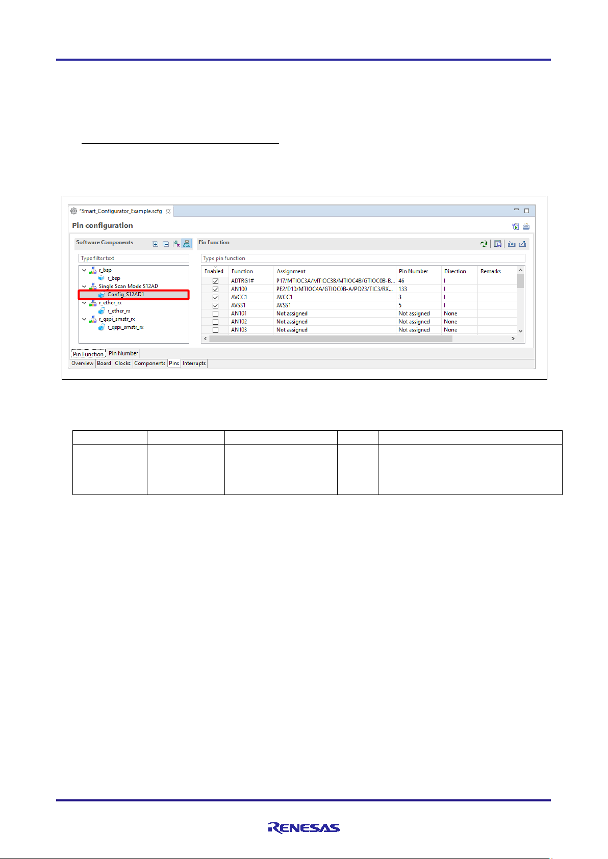
(1) Pin initialization for drivers with {ConfigName}
Pin functions are initialized in R_ConfigName_Create of the file ¥src¥smc_gen¥{ConfigName}¥{ConfigName}.c.
Pin initialization codes will be handled b e fore entering main().
Figure 6-5 Config_S12AD1 in Software Components View
by this driver. R_Systeminit in
r_cg_hardware_setup.c will call this
R20AN0451ES0130 Rev.1.30 Page 64 of 79
Jan 25, 2019
Page 65

RX Smart Configurator User's Guide: e² studio
Folder
File
Function
Driver
Description
r_pincfg
r_xxx_pinset.c
R_xxx_PinSet_xxxn
FIT
This API function initializes the pins used
(2) Pin initialization for drivers with r_xxx
(Note2)
The pin setting source file will be generated in ¥src¥smc_gen¥r_ pincfg folder with the name r_xxx_pinset.c.
The API functions in this file are called by the user from application codes.
Figure 6-6 r_ether_rx in Software Components View
(Note*2)
(Note*2,3)
Note *2: xxx is the name of a peripheral function.
*3: n is a peripheral channel number.
by this driver. Refer to the application note
in the corres ponding r_xxx folder before
calling this API function:
(Note*2)
¥src¥smc_gen¥r_xxx¥doc
R20AN0451ES0130 Rev.1.30 Page 65 of 79
Jan 25, 2019
Page 66
RX Smart Configurator User's Guide: e² studio
Folder
File
Function
Driver
Description
r_config
r_xxx_smstr_rx_pin_config.h
-
FIT
Macro definitions in this header file
r_xxx_smstr source files.
Folder
File
Function
Driver
Description
r_pincfg
Pin.c
R_Pins_Create
-
This file contains the initialization
in the [Pins] page except I/O ports.
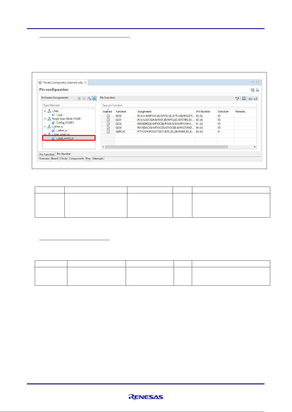
(3) Pin initialization for drivers with r_xxx_smstr
(Note4)
The pin setting header file will be generated in ¥src¥smc_gen¥r_config folder with the name
r_xxx_smstr_rx_pin_config.h.
The macro definitions i n thi s f ile will be handled in the r_xxx_smstr source files.
Figure 6-7 r_qspi_smstr_rx in Software Components View
(Note*4)
initialize the pins used by this driver.
These macros will be called in
Note *4: xxx is the name of a peripheral function.
(4) Reference to pin initialization codes
Refer to Pin.c in ¥src¥smc_gen¥r_pincfg folder for all peripheral pin functions used in the project (except I/O ports).
codes of all pin functions configured
R20AN0451ES0130 Rev.1.30 Page 66 of 79
Jan 25, 2019
Page 67

RX Smart Configurator User's Guide: e² studio
No
Item
Folder
File
Driver
Description
(1)
Priority
general
r_smc_interrupt.c
CG
This interrupt prior ity level setting
function.
(2)
Priority
{ConfigName}
{ConfigName}.c
CG
This interrupt prior ity level setting
function.
(3)
Vector
r_config
r_bsp_interrupt_config.h
CG
Vector number of software
handled b y r_bsp.
(4)
Fast
general
r_smc_interrupt.c
CG
Fast interrupt setting will be
function.
r_smc_interrupt.h
CG
Vector number of fast interrupt will
interrupt service routine.
(1)
Priority
general
r_smc_interrupt.h
-
Priority level of all interrupts
definitions in the application codes.
(2)
(1)
(4)
(3)
6.5 Initializing Interrupts
Configurati ons in the [Interrupts] page are generated in some source files.
Refer to the application note in the corresponding ¥src¥smc_gen¥r_xxx¥doc folder to initia liz e inter rupts used in r_xxx
modules (xxx is the name of peripheral function).
Figure 6-8 Interrupts Configuration in Interrupts View
Number
Interrupt
FIT
is for group interrupts
(Note5)
.
It is initialized in
R_Interrupt_Create of this file.
R_Systeminit in
r_cg_hardware_setup.c will call
this function before entering main()
is for normal interrupts and
software configurable interrupts A
(Note5)
and B
.
It is initialized in
R_ConfigName_Create of this file.
R_Systeminit in
r_cg_hardware_setup.c will call
this function before entering main()
configurable interrupts A and B
(Note5)
in the [Interrupts] tabbed
page will be mapped in this file and
initialized in R_Interrupt_Create of
this file. R_Systeminit in
r_cg_hardware_setup.c will call
this function before entering main()
(2)
Note *5: The type of interrupt depends on hardware specifications.
R20AN0451ES0130 Rev.1.30 Page 67 of 79
Jan 25, 2019
be defined in this file.
{ConfigName}_user.c will use this
macro definition to prepare a fast
configured in the [Interrupts]
tabbed page is defined in this file.
User can use these macro
Page 68

RX Smart Configurator User's Guide: e² studio
(2) Configuration
(1) Explanation information
6.6 Component Settings
6.6.1 FIT module configuration
1) Configuratio n for r_bsp
Configuration file of r_bsp is generated as r_bsp_config.h under the ¥src¥smc_gen¥r_config folder.
It contains clock-initialization and other MCU-related setting s (e.g. the package).
Some configurations are generated by the Smart Configurator. These configurations are marked with the
comment “Updated by GUI. Do not edit this value manually”.
Other configurations need to be manually configured by the user. As shown in the figure b elow, read (1)
Explanation information before setting the macro definition value in (2) Configuration.
Refer to the application note in the folder ¥src¥smc_gen¥r_bsp¥doc on how to modify r_bsp_config.h.
R20AN0451ES0130 Rev.1.30 Page 68 of 79
Jan 25, 2019
Figure 6-9 r_bsp_config.h
Page 69

RX Smart Configurator User's Guide: e² studio
(1) Explanation information
(2) Configuration
2) Configuration of FIT modules
Configuration files of FIT modules that are added to the project are generated as r_xxx_config.h under
¥src¥smc_gen¥r_config folder. (r_xxx is the name of FIT module)
These configurations need to be manually configured by the user. As shown in the figure below, read (1)
Explanation information before setting the macro definition value in (2) Configuration.
Refer to the application note in ¥src¥smc_gen¥r_xxx¥doc folder on how to modify r_xxx_config.h.
R20AN0451ES0130 Rev.1.30 Page 69 of 79
Jan 25, 2019
Figure 6-10 Example of r_xxx_config.h (r_ether_rx_config.h)
Page 70

RX Smart Configurator User's Guide: e² studio
6.6.2 FreeRTOS Kernel configuration
Configuration file of Renesas FreeRTOS_Kernel is generated as FreeRTOS_Kernel.h under the
¥src¥frtos_config.
Figure 6-11 FreeRTOSConfig.h
R20AN0451ES0130 Rev.1.30 Page 70 of 79
Jan 25, 2019
Page 71

RX Smart Configurator User's Guide: e² studio
smc_gen
board
doc
mcu
platform.h
r_bsp
r_xxx
r_config
r_bsp_config.h
r_bsp_interrupt_config.h
r_xxx_config.h
r_xxx_pin_config.h
doc
r_xxx_if.h
ref
src
en
jp
7. Creating User Programs
The Smart Configurator handles two component types, [Firmware Integration Technology] and [Code Generator], with
each requiring different methods to add custom code to the output source files. This section describes the methods to
add custom code for both components.
7.1 Adding Custom Code in the Case of Firmware Integration Technology (FIT)
When [Firmware Integration Technology] is selected as the component type, the configuration options are set in
r_xxx_config.h in the folder r_config. For the settings of the configuration options, refer to the application note (in the
doc folder) on the FIT module (r_xxx) which yo u ha ve added to the project tree.
If the target file already exists, the existing contents of the file are protected when source code is output.
Figure 7-1 Tree Structure of Directories and Files for a FIT Module
R20AN0451ES0130 Rev.1.30 Page 71 of 79
Jan 25, 2019
Page 72

RX Smart Configurator User's Guide: e² studio
/* Start user code for xxxx. Do not edit comment generated here */
7.2 Adding Custom Code in the Case of Code Generator
When [Code Generator] is selected as the component type, if files which have the same name already exist, new code
will be merge d only with the existing cod e that is b e tween the comments below.
/* End user code. Do not edit comment generated here */
In the case of [Code Generator], three files are generated for each of the specified peripheral functions. The file names
are “Config_xxx.h”, “Config_xxx.c”, and “Config_xxx_user.c” as the default, with “xxx” representing the name of the
peripheral module. For example, “xxx” will be “CMT3” for the compare-match timer (resource CMT3). The comments
to indicate where to add custom code are at the start and end of each of the three files. Comments to indicate where to
add user code are also added to the interrupt function for the perip heral module corresponding to Config.xxx_user.c.
The following examples are for CMT3 (Config_CMT3_user.c).
/*******************************************************************************
Pragma directive
*******************************************************************************/
/* Start user code for pragma. Do not edit comment generated here */
/* End user code. Do not edit comment generated here */
/*******************************************************************************
Includes
*******************************************************************************/
#include "r_cg_macrodriver.h"
#include "r_cg_userdefine.h"
#include "Config_CMT3.h"
/* Start user code for include. Do not edit comment generated here */
/* End user code. Do not edit comment generated here */
/*******************************************************************************
Global variables and functions
*******************************************************************************/
/* Start user code for global. Do not edit comment generated here */
/* End user code. Do not edit comment generated here */
/*******************************************************************************
* Function Name: R_Config_CMT3_Create_UserInit
* Description : This function adds user code after initializing the CMT3 channel
* Arguments : None
* Return Val ue : None
*******************************************************************************/
void R_Config_CMT3_Create_UserInit(void)
{
/* Start user code for user init. Do not edit comment generated here */
/* End user code. Do not edit comment generated here */
}
R20AN0451ES0130 Rev.1.30 Page 72 of 79
Jan 25, 2019
Page 73

RX Smart Configurator User's Guide: e² studio
/*******************************************************************************
* Function Name: r_Config_CMT3_cmi3_interrupt
* Description : This fu nction is CMI3 interrupt service ro utine
* Arguments : None
* Return Val ue : None
*******************************************************************************/
#if FAST_INTERRUPT_VECTOR == VECT_PERIB_INTB129
#pragma interrupt r_Config_CMT3_cmi3_interrupt(vect=VECT(PERIB,INTB129),fint)
#else
#pragma interrupt r_Config_CMT3_cmi3_interrupt(vect=VECT(PERIB,INTB129))
#endif
static void r_Config_CMT3_cmi3_interrupt(void)
{
/* Start user code for r_Config_CMT3_cmi3_interrupt. Do not edit comment generated here */
/* End user code. Do not edit comment generated here */
}
/* Start user code for adding. Do not edit comment generated here */
/* End user code. Do not edit comment generated here */
R20AN0451ES0130 Rev.1.30 Page 73 of 79
Jan 25, 2019
Page 74

RX Smart Configurator User's Guide: e² studio
8. Backing up Generated Source Code
The Smart Configurator has a function fo r backing up the source code.
The Smart Configurator generates a backup folder for the previously generated source code when new code is generated
by clicking on the [ (Generate Code)] button. <Date-and-T ime> indic a tes the date and time when the backup folder
is created after code generation.
<ProjectDir>¥trash¥<Date-and-Time>
R20AN0451ES0130 Rev.1.30 Page 74 of 79
Jan 25, 2019
Page 75
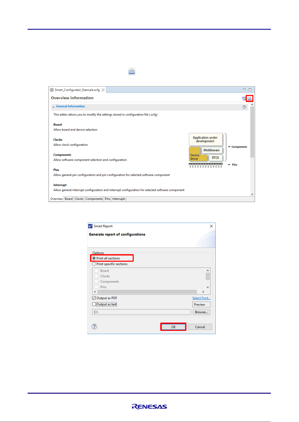
RX Smart Configurator User's Guide: e² studio
9. Generating Reports
The Smart Configurator generates a report on the configurations tha t the user works on. Follow the procedure below to
generate a report.
9.1 Report on All Configurations (Text File)
A report is output in response to clicking on the [ (Generate Report)] button in the Smart Configurator vie w.
Figure 9-1 Output of a Report on the Configuration (as a Text File)
Figure 9-2 Dialog Box for Output o f a Report
R20AN0451ES0130 Rev.1.30 Page 75 of 79
Jan 25, 2019
Page 76

RX Smart Configurator User's Guide: e² studio
9.2 Configuration of Pin Function List and Pin Number List (in csv Format)
A list of the configuration of pin functions and pin numbers (whichever is selected at the time) is output in response to
clicking on the [ (Save the list to .c sv file)] button on the [Pins] page of the Smart Configurator view.
Figure 9-3 Output of a List of Pin Functions or Numbers (in csv Format)
9.3 Image of MCU Package (in png Format)
An image of the MCU package is output in response to clicking on the [ (Save Package View to external image
file)] button o f t he [MCU Package] view.
Figure 9-4 Outputting a Figure of MCU Package (in png Format)
R20AN0451ES0130 Rev.1.30 Page 76 of 79
Jan 25, 2019
Page 77
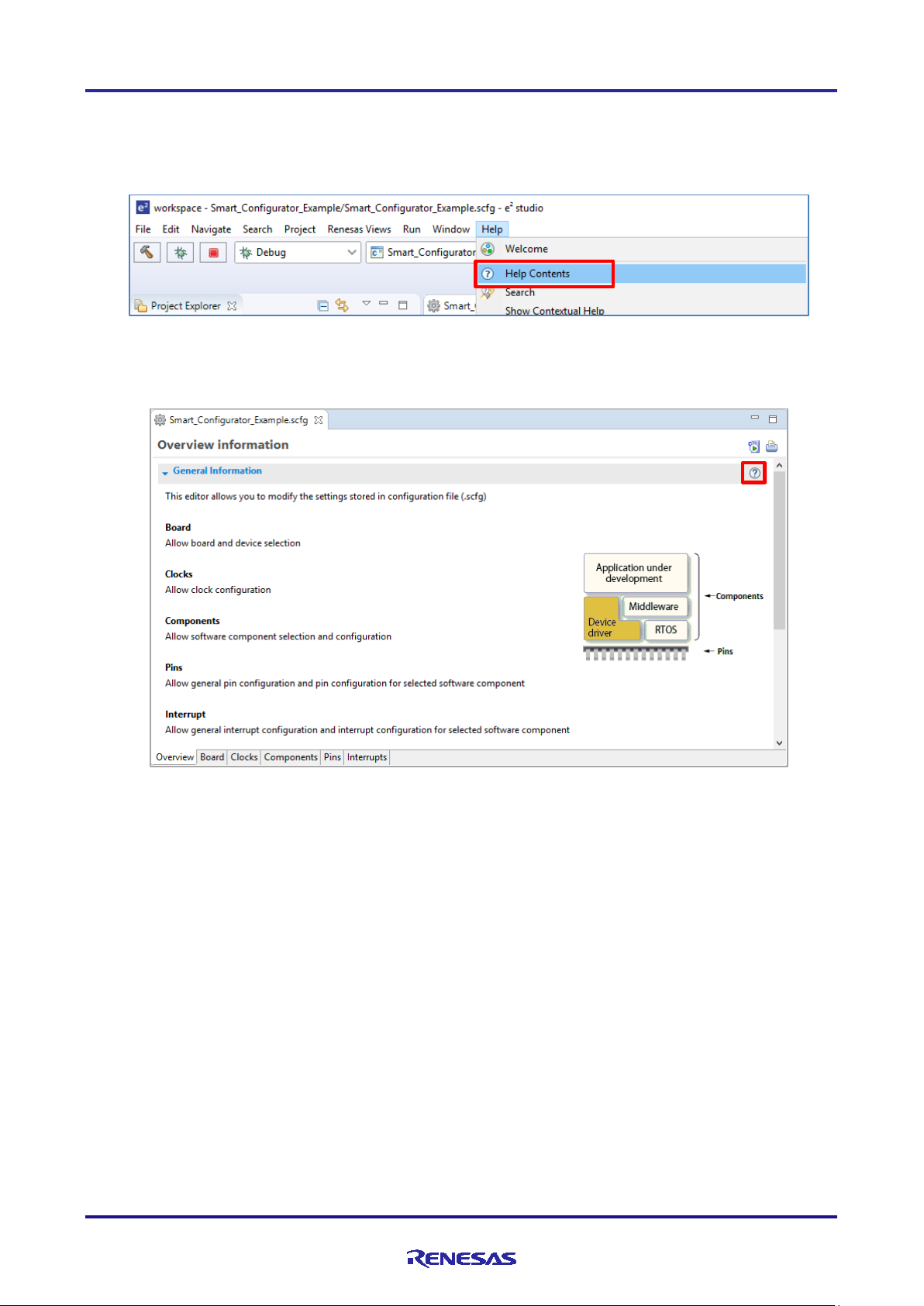
RX Smart Configurator User's Guide: e² studio
10. Help
10.1 Help
Refer to the help system from the e2 studio menu for detailed information on the Smart Configurator.
Figure 10-1 Help Menu
The help system can also be activated from the [Overview information] page.
Figure 10-2 Quick Start
R20AN0451ES0130 Rev.1.30 Page 77 of 79
Jan 25, 2019
Page 78

RX Smart Configurator User's Guide: e² studio
11. Documents for Reference
User’s Manual: Hardware
Obtain the latest version of the manual from the Renesas Electronics website.
Technical Update/Technical News
Obtain the latest information from the Renesas Electronics website.
User’s Manual: Development Environment
e2 studio Integrated Development Environment User’s Manual: Getting Started Guide (R20UT4374)
CC-RX Compiler User’s Manual (R20UT3248)
RX family Renesas FreeRTOS Application Note (R01AN4307)
(Obtain the latest version fro m the Renesas Electronics website.)
R20AN0451ES0130 Rev.1.30 Page 78 of 79
Jan 25, 2019
Page 79

RX Smart Configurator User's Guide: e² studio
Website and Support
Renesas Electronics Website
http://www.renesas.com/
Inquiries
http://www.renesas.com/contact/
All trademarks and registered trademarks are the property of their respective owners.
R20AN0451ES0130 Rev.1.30 Page 79 of 79
Jan 25, 2019
Page 80

Rev.
Date
Description
Page
Summary
1.00
Jul 31, 2017
-
First edition issued
1.10
Mar 20, 2018
-
Update to e² studio v6.2
4
1.2 Operating Environment updated
8
Figure 2-4 Select toolchain, device and debug setting updated
15
Figure 3-6 Add component updated
16
Figure 3-7 Add Code Generator component updated
19
Figure 3-12 Add FIT modules updated
26
Figure 3-22 Configure pins for r_ether_rx updated
30
Note added
36
4.1 Generated files structure
Description of the r_bsp folder in the table corrected
50
8.1 Troubleshooting added
53
9 Application Example updated
1.20
Nov 1, 2018
-
Update to e² studio v7.0
3
1. Overview updated
9
Figure 3-1 Procedure for Operations added
10
3.3 File to be Saved as Project Information added
11
3.4 Window added
19
4.1.3 Exporting board setting, 4.1.4 Importing board setting
added
21
Figure 4-7 [Components ] P age added
33
Figure 4-26 [Pins] Page ([Pin Function]), Figure4-26 [Pins]
Page ([Pin Number]) added
39
Figure4-35 [Interrupts] Page
42
Figure 5-1 Generating a So urc e File, Figure5-2 Source Files in
the Project Explorer added
55
7. Creating User Programs added
60
9.2 Configuration of Pin Function List and Pin Number List (in
added
61
10.1 Help added
1.30
Jan 1, 2019
-
Update to e² studio v7.3
9
2.2 Create a FreeRTOS project added
21
3.4.3 MCU Package view updated
23
4.1.1 Selecting the device updated
31
4.3.4 Download and import FIT sample project added
40
4.3.9 Setting a FIT Software Component update
41
4.3.10 Version change of FIT software component added
43
4.3.11 Setting the FreeRTOS Kernel added
44
4.3.12 Configure general setting of component added
45
Figure 4-41 [Pins] Page ([Pin Number]) updated
49
4.4.5 Pin setting using board pin configuration information
4.4.6 Pin filter feature added
53
4.6 MCU migration feature added
70
6.6.2 FreeRTOS Kernel configuration added
Revision History
csv Format), 9.3 Image of MCU Package (in png Format)
added
Page 81

General Precautions in the Handling of Microprocessing Unit and Microcontroller
Unit Products
The following usage notes are applicable to all Microprocessing unit and Microcontroller unit products from Renesas. For detailed usage notes on the
products covered by this document, refer to the relevant sections of the document as well as any technical updates that have been issued for the products.
1. Precaution against Electrostatic Discharge (ESD)
A strong electrical field, when exposed to a CMOS device, can cause destruction of the gate oxide and ultimately degrade the device operation. Steps
must be taken to stop the generation of static electricity as much as possible, and quickly dissipate it when it occurs. Environmental control must be
adequate. When it is dry, a humidifier should be used. This is recommended to avoid using insulators that can easily build up static electricity.
Semiconductor devices must be stored and transported in an anti-static container, static shielding bag or conductive material. All test and
measurement tools including work benches and floors must be grounded. The operator must also be grounded using a wrist strap. Semiconductor
devices must not be touched with bare hands. Similar precautions must be taken for printed circuit boards with mounted semiconductor devices.
2. Processing at power-on
The state of the product is undefined at the time when power is supplied. The states of internal circuits in the LSI are indeterminate and the states of
register settings and pins are undefined at the time when power is supplied. In a finished product where the reset signal is applied to the external reset
pin, the states of pins are not guaranteed from the time when power is supplied until the reset process is completed. In a similar way, the states of pins
in a product that is reset by an on-chip power-on reset function are not guaranteed from the time when power is supplied until the power reaches the
level at which resetting is specified.
3. Input of signal during power-off state
Do not input signals or an I/O pull-up power supply while the device is powered off. The current injection that results from input of such a signal or I/O
pull-up power supply may cause malfunction and the abnormal current that passes in the device at this time may cause degradation of internal
elements. Follow the guideline for input signal during power-off state as described in your product documentation.
4. Handling of unused pins
Handle unused pins in accordance with the directions given under handling of unused pins in the manual. The input pins of CMOS products are
generally in the high-impedance state. In operation with an unused pin in the open-circuit state, extra electromagnetic noise is induced in the vicinity of
the LSI, an associated shoot-through current flows internally, and malfunctions occur due to the false recognition of the pin state as an input signal
become possible.
5. Clock signals
After applying a reset, only release the reset line after the operating clock signal becomes stable. When switching the clock signal during program
execution, wait until the target clock signal is stabilized. When the clock signal is generated with an external resonator or from an external oscillator
during a reset, ensure that the reset line is only released after full stabilization of the clock signal. Additionally, when switching to a clock signal
produced with an external resonator or by an external oscillator while program execution is in progress, wait until the target clock signal is stable.
6. Voltage application waveform at input pin
Waveform distortion due to input noise or a reflected wave may cause malfunction. If the input of the CMOS device stays in the area between V
(Max.) and V
input level is fixed, and also in the transition period when the input level passes through the area between V
7. Prohibition of access to reserved addresses
Access to reserved addresses is prohibited. The reserved addresses are provided for possible future expansion of functions. Do not access these
addresses as the correct operation of the LSI is not guaranteed.
8. Differences between products
Before changing from one product to another, for example to a product with a different part number, confirm that the change will not lead to problems.
The characteristics of a microprocessing unit or microcontroller unit products in the same group but having a different part number might differ in terms
of internal memory capacity, layout pattern, and other factors, which can affect the ranges of electrical characteristics, such as characteristic values,
operating margins, immunity to noise, and amount of radiated noise. When changing to a product with a different part number, implement a systemevaluation test for the given product.
(Min.) due to noise, for example, the device may malfunction. Take care to prevent chattering noise from entering the device when the
IH
(Max.) and VIH (Min.).
IL
IL
Page 82

Notice
1. Descriptions of circuits, software and other related information in this document are provided only to illustrate the operation of semiconductor products and application examples. You are fully responsible for
the incorporation or any other use of the circuits, software, and information in the design of your product or system. Renesas Electronics disclaims any and all liability for any losses and damages incurred by
you or third parties arising from the use of these circuits, software, or information.
2. Renesas Electronics hereby expressly disclaims any warranties against and liability for infringement or any other claims involving patents, copyrights, or other intellectual property rights of third parties, by or
arising from the use of Renesas Electronics products or technical information described in this document, including but not limited to, the product data, drawings, charts, programs, algorithms, and application
examples.
3. No license, express, implied or otherwise, is granted hereby under any patents, copyrights or other intellectual property rights of Renesas Electronics or others.
4. You shall not alter, modify, copy, or reverse engineer any Renesas Electronics product, whether in whole or in part. Renesas Electronics disclaims any and all liability for any losses or damages incurred by
you or third parties arising from such alteration, modification, copying or reverse engineering.
5. Renesas Electronics products are classified according to the following two quality grades: “Standard” and “High Quality”. The intended applications for each Renesas Electronics product depends on the
product’s quality grade, as indicated below.
"Standard": Computers; office equipment; communications equipment; test and measurement equipment; audio and visual equipment; home electronic appliances; machine tools; personal electronic
"High Quality": Transportation equipment (automobiles, trains, ships, etc.); traffic control (traffic lights); large-scale communication equipment; key financial terminal systems; safety control equipment; etc.
Unless expressly designated as a high reliability product or a product for harsh environments in a Renesas Electronics data sheet or other Renesas Electronics document, Renesas Electronics products are
not intended or authorized for use in products or systems that may pose a direct threat to human life or bodily injury (artificial life support devices or systems; surgical implantations; etc.), or may cause
serious property damage (space system; undersea repeaters; nuclear power control systems; aircraft control systems; key plant systems; military equipment; etc.). Renesas Electronics disclaims any and all
liability for any damages or losses incurred by you or any third parties arising from the use of any Renesas Electronics product that is inconsistent with any Renesas Electronics data sheet, user’s manual or
other Renesas Electronics document.
6. When using Renesas Electronics products, refer to the latest product information (data sheets, user’s manuals, application notes, “General Notes for Handling and Using Semiconductor Devices” in the
reliability handbook, etc.), and ensure that usage conditions are within the ranges specified by Renesas Electronics with respect to maximum ratings, operating power supply voltage range, heat dissipation
characteristics, installation, etc. Renesas Electronics disclaims any and all liability for any malfunctions, failure or accident arising out of the use of Renesas Electronics products outside of such specified
ranges.
7. Although Renesas Electronics endeavors to improve the quality and reliability of Renesas Electronics products, semiconductor products have specific characteristics, such as the occurrence of failure at a
certain rate and malfunctions under certain use conditions. Unless designated as a high reliability product or a product for harsh environments in a Renesas Electronics data sheet or other Renesas
Electronics document, Renesas Electronics products are not subject to radiation resistance design. You are responsible for implementing safety measures to guard against the possibility of bodily injury, injury
or damage caused by fire, and/or danger to the public in the event of a failure or malfunction of Renesas Electronics products, such as safety design for hardware and software, including but not limited to
redundancy, fire control and malfunction prevention, appropriate treatment for aging degradation or any other appropriate measures. Because the evaluation of microcomputer software alone is very difficult
and impractical, you are responsible for evaluating the safety of the final products or systems manufactured by you.
8. Please contact a Renesas Electronics sales office for details as to environmental matters such as the environmental compatibility of each Renesas Electronics product. You are responsible for carefully and
sufficiently investigating applicable laws and regulations that regulate the inclusion or use of controlled substances, including without limitation, the EU RoHS Directive, and using Renesas Electronics
products in compliance with all these applicable laws and regulations. Renesas Electronics disclaims any and all liability for damages or losses occurring as a result of your noncompliance with applicable
laws and regulations.
9. Renesas Electronics products and technologies shall not be used for or incorporated into any products or systems whose manufacture, use, or sale is prohibited under any applicable domestic or foreign laws
or regulations. You shall comply with any applicable export control laws and regulations promulgated and administered by the governments of any countries asserting jurisdiction over the parties or
transactions.
10. It is the responsibility of the buyer or distributor of Renesas Electronics products, or any other party who distributes, disposes of, or otherwise sells or transfers the product to a third party, to notify such third
party in advance of the contents and conditions set forth in this document.
11. This document shall not be reprinted, reproduced or duplicated in any form, in whole or in part, without prior written consent of Renesas Electronics.
12. Please contact a Renesas Electronics sales office if you have any questions regarding the information contained in this document or Renesas Electronics products.
(Note 1) “Renesas Electronics” as used in this document means Renesas Electronics Corporation and also includes its directly or indirectly controlled subsidiaries.
(Note 2) “Renesas Electronics product(s)” means any product developed or manufactured by or for Renesas Electronics.
equipment; industrial robots; etc.
(Rev.4.0-1 November 2017)
SALES OFFICES
Refer to "http://www.renesas.com/" for the latest and detailed information.
Renesas Electronics Corporation
TOYOSU FORESIA, 3-2-24 Toyosu, Koto-ku, Tokyo 135-0061, Japan
Renesas Electronics America Inc.
1001 Murphy Ranch Road, Milpitas, CA 95035, U.S.A.
Tel: +1-408-432-8888, Fax: +1-408-434-5351
Renesas Electronics Canada Limited
9251 Yonge Street, Suite 8309 Richmond Hill, Ontario Canada L4C 9T3
Tel: +1-905-237-2004
Renesas Electronics Europe Limited
Dukes Meadow, Millboard Road, Bourne End, Buckinghamshire, SL8 5FH, U.K
Tel: +44-1628-651-700
Renesas Electronics Europe GmbH
Arcadiastrasse 10, 40472 Düsseldorf, Germany
Tel: +49-211-6503-0, Fax: +49-211-6503-1327
Renesas Electronics (China) Co., Ltd.
Room 1709 Quantum Plaza, No.27 ZhichunLu, Haidian District, Beijing, 100191 P. R. China
Tel: +86-10-8235-1155, Fax: +86-10-8235-7679
Renesas Electronics (Shanghai) Co., Ltd.
Unit 301, Tower A, Central Towers, 555 Langao Road, Putuo District, Shanghai, 200333 P. R. China
Tel: +86-21-2226-0888, Fax: +86-21-2226-0999
Renesas Electronics Hong Kong Limited
Unit 1601-1611, 16/F., Tower 2, Grand Century Place, 193 Prince Edward Road West, Mongkok, Kowloon, Hong Kong
Tel: +852-2265-6688, Fax: +852 2886-9022
Renesas Electronics Taiwan Co., Ltd.
13F, No. 363, Fu Shing North Road, Taipei 10543, Taiwan
Tel: +886-2-8175-9600, Fax: +886 2-8175-9670
Renesas Electronics Singapore Pte. Ltd.
80 Bendemeer Road, Unit #06-02 Hyflux Innovation Centre, Singapore 339949
Tel: +65-6213-0200, Fax: +65-6213-0300
Renesas Electronics Malaysia Sdn.Bhd.
Unit 1207, Block B, Menara Amcorp, Amcorp Trade Centre, No. 18, Jln Persiaran Barat, 46050 Petaling Jaya, Selangor Darul Ehsan, Malaysia
Tel: +60-3-7955-9390, Fax: +60-3-7955-9510
Renesas Electronics India Pvt. Ltd.
No.777C, 100 Feet Road, HAL 2nd Stage, Indiranagar, Bangalore 560 038, India
Tel: +91-80-67208700, Fax: +91-80-67208777
Renesas Electronics Korea Co., Ltd.
17F, KAMCO Yangjae Tower, 262, Gangnam-daero, Gangnam-gu, Seoul, 06265 Korea
Tel: +82-2-558-3737, Fax: +82-2-558-5338
© 2019 Renesas Electronics Corporation. All rights reserved.
http://www.renesas.com
Colophon 7.2
 Loading...