

Page 1
Application Note
Renesas Synergy™ Platform
RTC HAL Module Guide
Introduction
This module guide will enable you to effectiv ely use a module in your own design. Upon completion of this
guide, you will be able to add this module to your own design, configure it correctly for the target application
and write code, using the included application project code as a reference and efficient starting point.
References to more detailed API descriptions and suggestions of other application projects that illustrate
more adv anced uses of the module are av ailable in the Renesas Synergy Knowledge Base (as described in
the References section at the end of this document), and should be valuable resources for creating more
complex designs.
The Real-Time Clock (RT C) HAL module is a high-lev el API for RTC applications and is implement ed on
r_rtc. The RT C HAL module configures the RTC module and controls clock, calendar, and alarm functio n s .
The RTC uses the real-time clock module on the Synergy MCU. A user-defined callback can be created to
respond to any of the three supported interrupt types: alarm, periodic, or carry.
R11AN0059EU0103 Rev.1.03 Page 1 of 14
Mar.20.19
Page 2

Renesas Synergy™ Platform RTC HA L Module Guide
Contents
1. RTC HAL Module Features ...................................................................................................3
2. RTC APIs Overview ..............................................................................................................3
3. RTC HAL M odule Ope rational Ove rvi ew ................................................................................4
3.1 RTC HAL Module Important Operational Notes and Limitations..................................................... 4
3.1.1 RTC HAL Module Operational Notes....................................................................................... 4
3.1.2 RTC HAL Module Limit ations ................................................................................................. 5
4. Including the RTC HAL Module in an Application ...................................................................5
5. Configuring the RTC HAL Module..........................................................................................5
5.1 RTC HAL Module Clock Configuration ...................................................................................... 7
5.2 RTC HAL Module Pin Configuration .......................................................................................... 7
6. Using the RTC HAL Module in an Application ........................................................................7
7. The RTC HAL Module Application Project..............................................................................8
8. Customizing the RTC HAL Module for a Target Application ..................................................10
8.1 Change interrupt type ........................................................................................................... 10
8.2 Set periodic interrupt rate ...................................................................................................... 10
8.3 Set Alarm interrupt ............................................................................................................... 10
9. Running the RTC HAL Module Application Project ...............................................................10
10. RTC HAL Module Conclusion ..............................................................................................11
11. RTC HAL Module Next Steps ..............................................................................................11
12. RTC HAL Module Reference Information .............................................................................12
Revisio n History .........................................................................................................................14
R11AN0059EU0103 Rev.1.03 Page 2 of 14
Mar.20.19
Page 3
Renesas Synergy™ Platform RTC HA L Module Guide
Function N ame
Example API Call and Des cription
.open
g_rtc0.p_api->open(g_rtc0.p_ctrl, g_rtc0.p_cfg);
Open the RTC HAL.
.close
g_rtc0.p_api->close(g_rtc0.p_ctrl);
Close the RTC HAL.
.calendarTimeSet
g_rtc0.p_api->calendarTimeSet(g_rtc0.p_ctrl,
Set the calendar time.
.calendarTimeGet
g_rtc0.p_api->calendarTimeGet(g_rtc0.p_ctrl,
Get the calendar time.
.calendarAlarmSet
g_rtc0.p_api->calendarAlarmSet(g_rtc0.p_ctrl,
.calendarAlarmGet
g_rtc0.p_api->calendarAlarmGet(g_rtc0.p_ctrl,
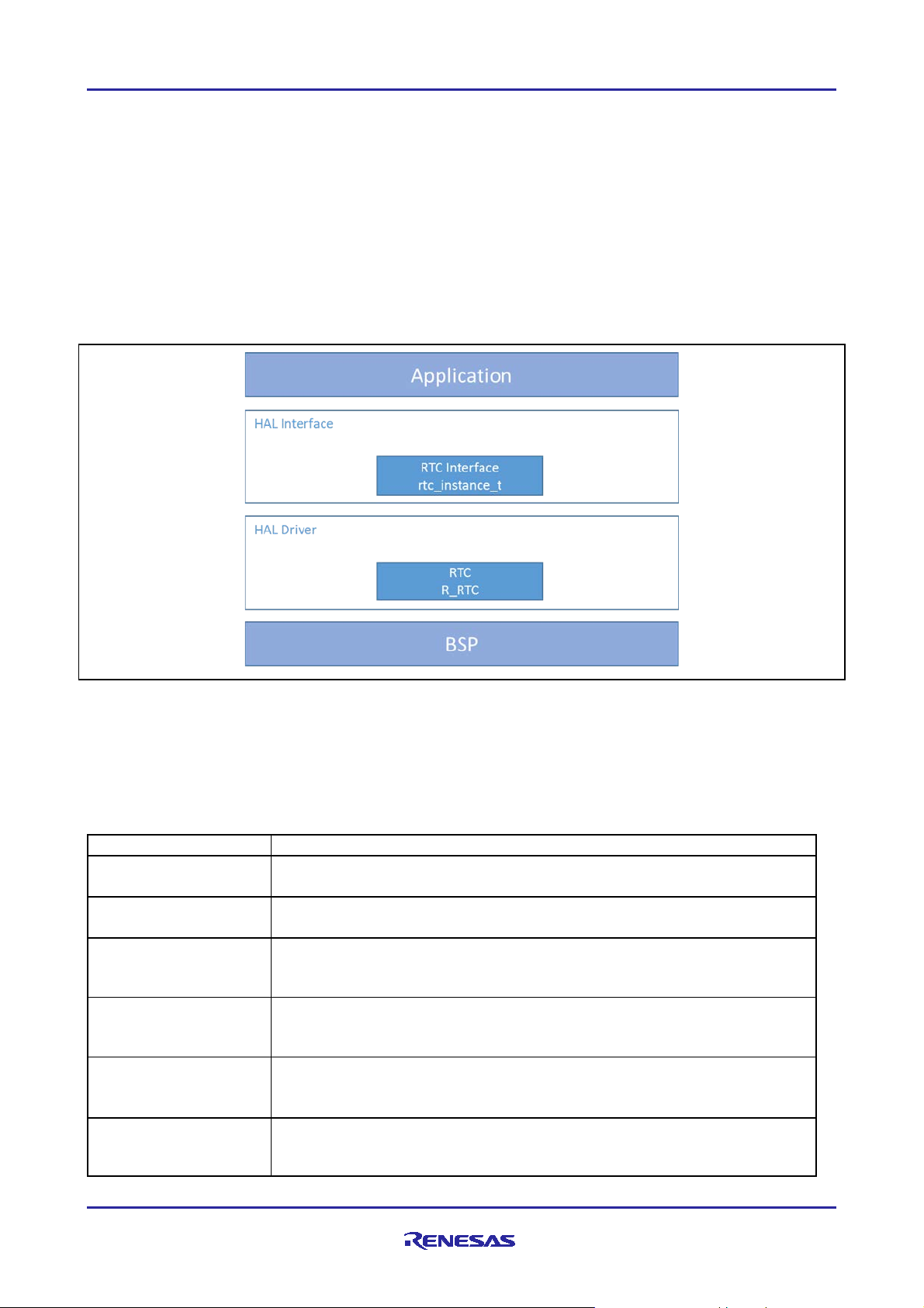
1. RTC HA L Module Features
The RT C HAL module supports the following functions of the real-time clock:
• RT C peripheral configuration
• RT C time and date get and set
• RT C time and date alarm get and set
• RT C time counter start and stop
• RT C alarm, periodic and carry event notification
• RT C ev ent type enable and disable
• RTC event rat e configuration
• RT C clock source get and set
Figure 1. RTC HAL Module Block Diagram
2. RTC APIs Overvi ew
The RTC HAL module defines APIs for opening, closing, setting alarms, starting, and stopping RT C
operations. A complete list of the available APIs, an example API call, and a short description of each can be
found in the following table. A table of all applicable status return v alues follows the API summary table.
Table 1. RTC H AL Module API Summary
&start_ti me _struc t_ in, true );
¤t_time_struct_out);
&in_alarm_time_struct_in, true);
Set the calendar alarm time.
&get_alarm_time_struct_out);
Get the calendar alarm time.
R11AN0059EU0103 Rev.1.03 Page 3 of 14
Mar.20.19
Page 4
Renesas Synergy™ Platform RTC HA L Module Guide
.calendarCounterStart
g_rtc0.p_api->calendarCounterStart(g_rtc0.p_ctrl);
Start the calendar counter.
.calendarCounterStop
g_rtc0.p_api->calendarCounterStop(g_rtc0.p_ctrl);
Stop the calendar counter.
.irqEnable
g_rtc0.p_api->irqEn ab le(g_r tc 0. p_ctrl , CA LLBACK );
Enable the alarm irq.
.irqDisable
g_rtc0.p_api->irqDisable(g_rtc0.p_ctrl, CALLBACK);
Disable the alarm irq.
.periodicIrqRateSet
g_rtc0.p_api->periodicIrqRateSet(g_rtc0.p_ctrl, Rate);
Set the periodic irq rate.
.infoGet
g_rtc0.p_api->infoG et (g_rtc 0. p_ ctrl, cl k_ src);
.versionGet
g_rtc0.p_api->versionGet(&version);
Retrieve the API v ersion with the version pointer.
Name
Description
SSP_SUCCESS
Function executed successfully
SSP_ERR_ASSERTION
API dependent error
SSP_ERR_INVALID MODE
Inval id mode
SSP_ERR_INVALID_PTR
Inval id paramet er
Return the currently configure clock source for the RTC.
Note: For more complete descriptions of operation and definitions for the function data structures, typed efs,
defines, API data, API structures, and f unction var iables, rev iew the SSP User’s Manual API
References for the associated module.
Table 2. Status Return Values
Note: Lower-lev el driv ers may return common error codes. Refer to the SSP User’s Manual API Ref erences
for the associated mod ule for a definition of all relevant status return v alues.
3. RTC HA L Module Operational Overview
The RTC HAL module controls the operation of the real-time clock module on a Synergy MCU. T he typical
RT C application configures the real-time clo ck controller periodically based on a system configuration driven
by the user. Common operations include setting the time, setting an alarm, configuring a periodic interrupt
and starting or stopping operation. An R T C application usually consists of calls to the RTC HAL module and
an optional callback from the ISR handler.
• T he RTC HAL module can use two main clock sources:
o A Low Speed On-Chip Oscillator (LOCO) with lower power but less accuracy
o A sub-clock oscillator with higher power, increased accuracy and more cost (external crystal require d)
• T he RTC HAL module supports three differ ent interrupt types:
o An alarm interrupt generated on a match of any combination of year, month, day, day of the week,
hour, minute and second
o A periodic interrupt generated ev ery 2, 1, 1/2, 1/4, 1/8, 1/16, 1/32, 1/64, 1/128, or 1/256 second(s)
o A carry interrupt when ei t her a carry to t he second counter occurs or when a carry to the R64CNT
counter occurs during a read access to the 64-Hz counter
• A user-defined callback function can be registered (in the open API call) and will be called from the
interrupt serv ice routine (ISR) for any supported interrupt typ e. When called, it is passed a pointer to a
structure (rtc_callback_args_t) that holds a user-defined context pointer and an indication of which
type of interrupt was fired.
3.1 RT C HAL Module Important Ope rational Notes and Limitations
3.1.1 RT C HA L Modul e Ope r at ional Not e s
The RTC HAL module must be opened before any of the other RTC module APIs can be called. A
configuration structure is passed to the open call which specif ies the clock source, the name of the user
callback from the ISR handler, and a user-specif ied context for the callback. Conf iguration structures can be
either manually defined or generated by the ISDE based on user input during the configuration process.
R11AN0059EU0103 Rev.1.03 Page 4 of 14
Mar.20.19
Page 5
Renesas Synergy™ Platform RTC HA L Module Guide
Resource
ISDE Tab
Stacks Selection Sequence
r_rtc0 RTC HAL on r_rtc
Threads
New Stack> Driv er> Timers> RTC HAL on r_rtc
Functions in the driv er can be accessed by either making direct calls to the HAL layer or by using the RTC
interface structure. The name of this interface structure is based on the name setting entered in the module
configuration. For example, if the name is g_rtc, then the interface structure is called g_rtc_api.
3.1.2 RTC HAL Mod ule Limitations
This module has no support for the following functions:
• Binary-count mode
• Binary alarm get and set
• Binary time get and set
• Clock-error correction
• 1-Hz/64-Hz Clock output
Refer to the most recent SSP Release Notes for any additional operational limitations for this module.
4. Including the RTC HA L Module in an A pplication
This section describes how to include the RTC HAL module in an application using the SSP configurator.
Note: It is assumed that you are familiar with creating a project, adding threads, adding a stack to a thread
and configuring a block within the stack. If you are unfamiliar with any of these items, refer to the first
few chapters of the SSP User’s Manual to learn how to manage each of these important steps in
creating SSP-based applications.
To add the RT C Driver to an application, simply add it to a thread using the stacks selection sequence giv en
in the following table. (The def ault name for the RTC is r_rtc0. This name can be changed in the associated
Properties window.)
Table 3. RTC Driver Selection Sequence
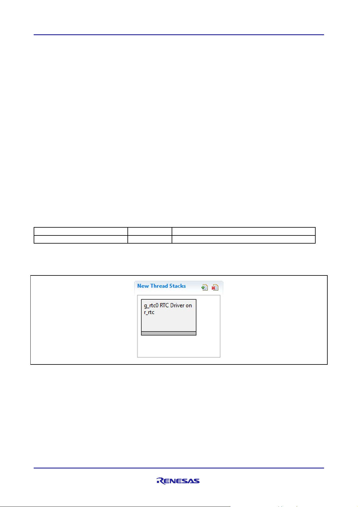
When the RTC HAL module on r_rtc is added to the thread stack as shown in the following, the configurator
automatically adds any needed lower-lev el modules. Modules with a Gray band are individual modules that
stand alone.
Figure 2. RTC HAL Module Stack
5. Configuring the RTC HA L Module
The RTC HAL module must be configured for the desired operation. The SSP configuration window
automatically identifies (by highlighting the block in red) any required configuration selections, such as
interrupts or operating modes, which must be configured for lower-lev el modules for successful operation.
Also, only those properties that can be changed without causing conflicts are available for modification.
Other properties are ‘locked’ and are not available for changes, and are identified with a lock icon f or the
‘locked’ property in the Properties window in the ISDE. This approach simplifies the configuration process
and makes it much less error-prone than prev ious ‘manual’ approaches to conf iguration. The available
configuration settings and defaults for all the user-accessible properties are giv en in the Properties tab within
the SSP configurator and are shown in the following tables for easy reference.
R11AN0059EU0103 Rev.1.03 Page 5 of 14
Mar.20.19
Page 6

Renesas Synergy™ Platform RTC HA L Module Guide
Parameter
Value
Description
Parameter Checking
Enable
BSP, Enabled, Disabled
(Default: BSP)
Enable or disable parameter error
checking
Name
g_rtc0
The name to be used for the RTC
See the example code below.
Clock Source
LOCO, Sub-clock
(Default: LOCO)
Clock source for the RTC block
Error Adjustment
Value
0
Important: Deprecated
configuration field. Must be 0.
Error Adjustment
Type
None, Add prescaler, Subtract prescaler
(Default: None)
Important: Deprecated
configuration field. Must be None.
Callback
NULL
The name of the ISR that is called
interrupt caused it to be called.
RTC ALA RM
Priority 0 (highest),
(Default: Priority 5)
Priority lev el for RTC alarm
RTC PE RIOD
Priority 0 (highest),
(Default: Priority 6)
Priority lev el for RTC period
RTC CARRY
Priority 0 (highest),
(Default: Priority 7)
Priority lev el for RTC carry
One of the properties most often identified as requiring a change is the interrupt priority. This configuration
setting is available within the Properties window of the associa ted module. Simply select the indicated
module and then view the Properties window. The interrupt settings are often toward the bottom of the
properties list, so scroll down until they become av ailable. Also, note that the interrupt priorities listed in the
Properties window in the ISDE include an indication of the v alidity of the setting based on the targeted MCU
(CM4 or CM0+). This lev el of detail is not included in the following configuration properties tables, but is
easily v isible with the ISDE when configuring interrupt-priority lev els.
Note: You may want to open your ISDE, create the module, and explore the property settings in parallel
while looking over the following configuration table settings. This will help orient you and can be a
useful hands-on approach to learning the ins and outs of dev eloping with SSP.
Table 4. Configuration Set tings for the RTC H AL Module on r_ rt c
module control block instance.
This name is also used as the
prefix of the other var iable
instances.
when one of the three interrupts
fire. The argument passed into this
ISR has an indication of which
1,2,3,4,5,6,7,8,9,10,11,12,13,14,15
(lowest, not v alid if using Thread X ),
Disabled
1,2,3,4,5,6,7,8,9,10,11,12,13,14,15
(lowest, not v alid if using Thread X ),
Disabled
1,2,3,4,5,6,7,8,9,10,11,12,13,14,15
(lowest, not v alid if using Thread X ),
Disabled
Note: The example values and defaults are for a project using the Synergy S7G2 MCU. Other MCUs may
have different default v alues and available configuration settings.
In some cases, settings other than the defaults for a module can be desirable. For example, it might be
useful to select a different clock source than the default. The configurable properties for the lower-lev el stack
modules are given in the following sections for comple teness and as a reference.
interrupt
interrupt
interrupt
R11AN0059EU0103 Rev.1.03 Page 6 of 14
Mar.20.19
Page 7

Renesas Synergy™ Platform RTC HA L Module Guide
5.1 RTC HA L Module Clock Configuration
The RTC HAL module can use the following clock sources:
• LOCO (Low Speed On-Chip Oscillator)
Lower power consumption
Less accurate
• Sub-clock oscillator
Higher power cons um pti on
More accurate
More cost (requires a crystal)
The LOCO is the default selection during co nf iguration.
5.2 RTC HAL Module Pin Configuration
The RTC does not currently support outputs, so no output pin selections are available.
6. Using the RTC HAL Module in an Applica tion
The typical RTC application conf igures the real-time clock controller periodically based on a system
configuration driv en by the user. Examples include setting the time, setting an alarm, configuring a periodic
interrupt, and so forth. An RTC application consists of calls to the RT C module and optional ISR callbacks.
The RTC module must be opened before any of the other APIs can be called. A con figuration structure is
passed to the open call which specifies the clock source, the names of the ISR callbacks, and the user-
specified context for the handler. Configuration structures can be either manually defined or generated by
the ISDE based on user input during the configuration process. Functions in the module can be accessed by
using the RTC interface structure. The name of this interface structure is based on the name setting entered
in the module configuration.
The typical steps in using the RTC periodic IRQ in an application are:
1. Initialize the RTC using the open API.
2. Set periodic IRQ rate using the periodicIrqRateSet API.
3. Start calendar counter using the calendarCounterStart API.
4. Enable interrupt using the irqEnable API.
These common steps are illustrated in a typical operational flow diagram in the figure below:
Figure 3. Flow Diagram of a Typical RTC Periodic Int errupt Application
R11AN0059EU0103 Rev.1.03 Page 7 of 14
Mar.20.19
Page 8

Renesas Synergy™ Platform RTC HA L Module Guide
The typical steps in using the RTC Alarm IRQ in an application are:
1. Initialize the RTC using the open API.
2. Set calendar time using the calendarTimeSet API.
3. Set alarm time using the calandarAlarmSet API.
4. Start calendar counter using the calendarCounterStart API.
These common steps are illustrated in a typical operational flow diagram in the following figure:
Figure 4. Flow Diagram of a Typi ca l RTC A larm In t errupt Applic at ion
7. The RTC HA L Module A pplication Project
The application project associated with this module guide demonstrates the previously mentioned steps in a
full design. You may want to import and open the application project within the ISDE and view the
configuration settings for the RTC HAL module. You can also read ov er the code (in rtc_hal_a pi_m g.c
and rtc_hal_mg.c), which illustrates the RTC APIs in a complete design.
The application project demonstrates the typical use of the RTC HAL module APIs. The application project
HAL entry initializes the RTC HAL modules. In the application project, the initialized RT C HAL module
generates an interrupt periodically at ev ery two seconds. Additionally, the applica tion project generates an
alarm interrupt, when the Alarm Second value matches the v alue of Clock Second. A user-callback
function is entered when either of these interrupts is generated. If the callback f unction is called due to
periodic interrupt, the function toggles LED2 on the board. In case a callback function call was made due to
an alarm interrupt, the function toggles LED3 on the board. An alarm interrupt generates ev ery minute
starting from 03:05:05 (HH:MM:SS). LED1 shows activity on the board and toggles ev ery second. Also, the
clock time is printed at ev er y one second using semi-hosting.
The following table identifies the target v ersions for the associated software and hardware used by the
application project:
R11AN0059EU0103 Rev.1.03 Page 8 of 14
Mar.20.19
Page 9

Renesas Synergy™ Platform RTC HA L Module Guide
Resource
Revision
Description
e2 studio
5.3.1 or later
Integrated Solution Development Env ironment
SSP
1.2.0 or later
Synergy Software Platform
IAR Embedded Workbench® f or Renesas
Synergy
SSC
5.3.1 or later
Synergy Standalone Configurator
SK-S7G2
v 3.0 to v3.1 or lat er
Starter Kit
Table 5 Software and Hardware Resources Used by the Application Project
IAR EW for Synergy 7.71.2 or later
A simple flow diagram of the application project is giv en in the following figure:
Figure 5 RTC A ppli ca tion Proj e ct Flo w D iagram
The rtc_hal_mg.c/.h f iles are in the project once it has been imported into the ISDE. You can open these
files within the ISDE and follow along with the description provided to help identify key uses of APIs.
All the configuration and initialization steps are in the rtc_hal_mg.c file. This file also uses semi-hosting to
display results using printf() if #define SEMI_HOSTING is uncommented in the rtc_hal_mg.h file.
The first section in the rtc_hal_mg.h f ile includes #defines for semi-hosting, periodic interrupt, alarm
interrupt, and periodic-interrupt rate. Other #defines in this header file initialize the alarm and calendar
R11AN0059EU0103 Rev.1.03 Page 9 of 14
Mar.20.19
Page 10

Renesas Synergy™ Platform RTC HA L Module Guide
ISDE Property
Value Set
Parameter Checking Enable
Enabled
Name
g_rtc0
Clock Source
LOCO
Configure RTC hardware i n open() call
Yes
Error Adjustment Value
0
Error Adjustment Type
None
Callback
rtc_irq_callback
Alarm Interrupt Priority
Priority 3
Period Interrupt Priority
Priority 3
Carry Interrupt Priority
Priority 12
structures to set/get values to/from the RTC timer. T he last section in this file has the prototype for the
functions used in the application.
The associated source file, rtc_hal_mg.c, defines the entry function rtc_IRQ_init() for the RTC timer
that initializes and configures the RTC HAL module. Th is file includes a user-callback function that toggles
the respective LEDs based on a generated interrupt.
Note: This description assumes that you are familiar with using printf()with the Debug Console in the
Synergy Software Package. I f you are unfamiliar with this, refer to the “How do I Use Printf() with the
Debug Console in the Synergy Software Package” Knowledge Base article, av ailable as described in
the References section at the end of this document. Alternativ ely, the user can see results v ia the
watch v ariables in the debug mode.
A few key properties are configured in this application project. T hese properties support the required
operations and the physical properties of the target board and the MCU dev ice. T he following table lists
properties with the v alues set for this specific project. You can also open the applica tion project and v iew
these settings in the Properties w indow as a hands-on exercise.
Table 6 RTC Conf iguration Set t in gs for the Applica ti on Proj e ct
8. Custom izing the RTC HA L Module for a Target A pplication
8.1 Change interrupt ty pe
To change the interrupt type or to support more than one interrupt type, enable interrupt types in the
configuration table. For the periodic interrupt, add the periodic interrupt ev ent in the interrupt enable API.
8.2 Set periodic interrupt rate
A periodic interrupt rate can be configured to generate an interrupt at ev ery 2, 1, 1/2, 1/4, 1/8, 1/16, 1/32,
1/64, or 1/256 second(s) using the periodic IR Q rate set API.
8.3 Set Alarm interrupt
To set an alarm interrupt, configure the RT C alarm time structure to enable the alarm for v arious entity
matches and set the time in the RTC time sub-structure. Be sure to initia lize the match var iables with 1 or
true in the RTC alarm time structure to generate an alarm interrupt when the RTC time matches the RT C
alarm time.
9. Running the RTC HA L Module A pplication Project
To run the RT C HAL module application project and see it executed on a target kit, you import the
application code into your ISDE, compile, and run debug. Refer to Importing a Renesas Synergy Project
(11an0023eu0116-synergy-ssp-import-guide.pdf, included in this package) for instructions on
importing the project into e
To implement the RTC H AL module application in a new project, follow the steps for defining, configuring,
auto-generating files, adding code, compiling, and debugging on the target kit. Following these steps is a
hands-on approach that can help make the development process with SSP more practical, while just reading
ov er this guide tends to be more theoretical.
2
studio or IAR EW for Synergy and building/running the application.
R11AN0059EU0103 Rev.1.03 Page 10 of 14
Mar.20.19
Page 11

Renesas Synergy™ Platform RTC HA L Module Guide
Note: The following steps are described in sufficient detail for someone experienced with the basic flow
through the Synergy dev elopment process. If these steps are not familiar, refer to the first few
chapters of the SSP User’s Manual for a description of how to accomplish these steps.
To create and run the RTC application project, simply f ollow these steps:
1. Create a new Renesas Synergy project for the SK-S7G2 board called RTC_HAL.
2. Select the BSP or Blinky project template.
3. Open Configuration.xml file from the project.
4. In t he Threads tab, select HAL/Com mon and add the RTC HAL on r_rtc stack from the HAL/Common
Stacks Drivers Timers.
5. Change the configuration settings for the RTC HAL stack fro m the configuration properties window.
a. Set Alarm interrupt priority
b. Set Period Interrupt priority
c. Set user-callback function name
6. Click on the Generate Project Content button.
7. Add the code from the supplied project file rtc_hal_mg.c/.h and add an entry function in
hal_entry.c t hat calls rtc_initiate().
8. Compile the application without errors and warnings.
9. Connect to the USB micro cable at J19 on SK-S7G2 board and connect other end of USB cable to the
Host.
10. Start to debug the application.
11. As an output, LED1, LED2 and LED3 will toggle based on v arious ev ents as follows:
a. LED1: Toggles ev ery 1 second to show activity on board.
b. LED2: Toggles ev ery 2 seconds from Periodic interrupt callback function.
c. LED3: Toggles ev ery minute after 03:05:05 (HH:MM:SS) when clock second value matches with the
Alarm second value 05.
d. If the user enables the semi-hosting option from rtc_hal_mg.h file, the output on console will look
like the following figure:
Figure 6 Example O utput f rom R TC H A L Modu le A ppli ca tion Proj e ct
10. RTC HA L Module Conclusion
This module guide has prov ided all the background information needed to select, add, configure, and use the
module in an example project. Many of these steps were time consuming and error-prone activ ities in
prev ious generations of embedded systems. The R enesas Synergy™
time consuming and remov es the common errors, like conflicting configuratio n settings or incorrect selection
of lower-level drivers. The use of hi gh-level APIs (as demonstrated in the application project) illustrates
additional development time sav ings by allowing work to begin at a high level and avoiding the time required
in older development environments to use or, in some cases, create, lower-lev el driv ers.
Platform makes these steps much l e s s
11. RTC HA L Module Next Steps
After you have mastered a simple RT C HAL module project, you may want to rev iew a more complex
example.
R11AN0059EU0103 Rev.1.03 Page 11 of 14
Mar.20.19
Page 12

Renesas Synergy™ Platform RTC HA L Module Guide
The Developer Exam pl es tem plate, as described in section 12, has an example of the RTC HAL module-use
that complements the application project described in this document. Other application projects and
application notes that demonstrate RT C H AL module-use are available as described in section 12.
12. RTC HA L Module Reference Information
SSP User Manual: Available in html format in the SSP distribution package and as pdf f rom the Synergy
Gallery.
Links to all the most up-to-date r_rtc module reference materials and resources are available on the Synergy
Knowledge Base:
us.knowledgebase.renesas.com/English_Content/Renesas_Synergy%E2%84%A2_Platform/Renesas_Syne
rgy_Knowledge_Base/r_rtc_Module_Guide_Resources.
https://en-
R11AN0059EU0103 Rev.1.03 Page 12 of 14
Mar.20.19
Page 13

Renesas Synergy™ Platform RTC HA L Module Guide
We bsite and Suppor t
Visit the following v anity URLs to learn about key elements of the Synergy Platform, download components
and related documentation, and get support.
Synergy Software www.renesas.com/synergy/software
Synergy Software Package www.renesas.com/synergy/ssp
Software add-ons www.renesas.com/synergy/addons
Software glossary www.renesas.com/synergy/softwareglossary
Dev elopment tools www.renesas.com/synergy/tools
Synergy Hardware www.renesas.com/synergy/hardware
Microcontrollers www.renesas.com/synergy/mcus
MCU glossary www.renesas.com/synergy/mcuglossary
Parametric search www.renesas.com/synergy/parametric
Kits www.renesas.com/synergy/kits
Synergy Solutions Gallery www.renesas.com/synergy/solutionsgallery
Partner projects www.renesas.com/synergy/partnerprojects
Application projects www.renesas.com/synergy/applicationprojects
Self-serv ice support resources:
Documentation www.renesas.com/synergy/docs
Knowledgebase www.renesas.com/synergy/knowledgebase
Forums www.renesas.com/synergy/forum
Training www.renesas.com/synergy/training
Videos www.renesas.com/synergy/videos
Chat and web ticket www.renesas.com/synergy/resourcelibrary
R11AN0059EU0103 Rev.1.03 Page 13 of 14
Mar.20.19
Page 14

Renesas Synergy™ Platform RTC HA L Module Guide
Rev.
Date
Description
Page
Summary
1.00
May.15.17
-
Initial Release
1.01
Aug.3.17
7
Update to Hardware and Software Resources Table
1.02
Sep.12.17
-
Fixed a bug in example code that surfaced with 1.3.0 where
Minor formatting and language edits to the document.
1.03
Mar.20.19
9, 11
Updated files required for operation
Revision History
the initial year value was too low. It was set to 100.
R11AN0059EU0103 Rev.1.03 Page 14 of 14
Mar.20.19
Page 15

Corporate Headquarters
Contact information
www.renesas.com
www.renesas.com/contact/.
Trademarks
of their respective owners.
Notice
1. Descriptions of circuits, so ftw are and other related infor mation in this documen t are pro vided onl y to illustrat e the operation o f semiconductor produc t s
and application examples. You are full y responsible for the incorporation or any other use of the circuits, softw are, and in formation in the design of you r
product or sy st em. Ren esas Elec tron ics disclaims an y and all liability for any losses and damages inc urred by you or third parties arising from the use
of these circuits, so ftware, or informat ion.
2. Renesas Electronics hereby expressly disclaim s an y warranties agains t and liability for infringem ent or an y other cla ims invo lving patents, cop yrights ,
or other intellectual property rights of third parties, b y or arising fr om the use of Renesas Electronic s produ cts or technical info rma tion desc ribed in this
document, including but not limited to, the product data, draw ings , charts, progr ams, algorithms, and applicat ion exa mple s.
3. No license, express, implied or otherwis e, is granted hereby under any patents, copyrights or other intellect ual propert y rights of Renesas Electronics
or others.
4. You shall not alter, modify, copy, or reverse engineer any Renesas Electronics product, whet her in w hole or in part. Rene sas Elec troni cs disclaim s a ny
and all liability for any losses or dama ges incurred b y you or third parties arising from such alteration, mod ificat ion, copying or reverse engineering.
5. Renesas Electronics products are classifie d according t o the follow ing two quality grades: “Standard” and “H igh Qualit y”. T he intended applications for
each Renesas Electronics produc t depend s on the product’s qualit y grade, as indicated below.
"Standard": Computers; office equipmen t; commu nica tions equipm ent ; test and measurem ent equipment ; audio and visual equip men t; home
"High Quality": T ransportation equipment (autom obiles, trains , ships, etc.); tra ffic control (traffic lights); large-scale co mmunic at ion equipm ent ; key
Unless expressly designated as a high reliability product or a product for harsh environments in a Renesas Electron ics data sheet or other Renesas
Electronics document, Rene sas Elec tronics produc ts are not intended or autho riz ed for use in products or systems that may pose a direct threat to
human lif e or bodily injury (artificial life support devices or systems ; surgic al implan tations ; etc.), or may cause serious property damage (s pace
sy ste m; unders ea repeat ers ; nuclear pow er control systems ; aircraft control s ystems ; key plant s ystems; militar y equipment; etc.) . Renesa s Electronics
disclaims any and all liability for any damages or losses incurred b y you or any third parties arising fro m the use of any Renesas Electronics product
that is inconsistent with any Renesas Electronic s data sheet, user’s manua l or other Renesas Electron ics document .
6. When using Renesas Electronics products , re fer to the lates t product in formation (data sheet s, user’s man uals, applic ati on notes, “General Notes for
Handling and Using Semiconduct or De vices” in the reliabilit y handboo k, etc.), and ensur e that usage conditions are w ithin the ranges specified by
Renesas Electronics with respec t to maximum ratin gs, operat ing pow er supply voltage range, heat dissipat ion chara cteris tics , installation, etc. Renes a s
Electronics disclaims any and all liability for any malfunct ions , failure or accident arising out of the use of Renesas Electr onics produc ts out side o f such
specified ranges.
7. Although Renesas Electronics endea vors to improve the quality and reliabilit y of Renesa s Electro nics produc ts, semicon ductor produc t s ha ve speci fic
characteristics, such as the occurrenc e of failure at a certain rate and mal functions under certain use cond itions. Unless designat ed as a high reliabilit y
product or a product for harsh environ men ts in a Renesas Electro nics data sheet or other Renesas Electro nics docu men t, Renesas Electronic s
products are not subject to radiation resistance design. You are respo nsibl e for impleme nting safety measures to guard again st the possibil it y of bodily
injury, injury or damage caused by fire, and/or danger to the public in the event of a failure or malfunct ion of Renesa s Electron ics produc ts, such as
saf ety design for hardw are and so ftware, inclu ding but not limited to redundanc y, fire control and malfu nction prevention, appropriat e treatment for
aging degradation or any other appropriat e me asur es. Becau se the evaluation o f microcompu ter softw are alone is very di fficult and impractical , yo u are
responsible for evaluating the sa fety of the final products or s ystems manufactured by you.
8. Please contact a Renesas Electronics sales o ffice for details as to environment al matters such as the environm enta l compati bility of each Renesas
Electronics product. You are respons ible for carefu lly and sufficie ntl y investigat ing applicable law s and regulations that regulat e the inclusio n or use of
controlled substances, inclu ding w ithout limitat ion, the EU RoHS Direc ti ve, and using Renesas Electro nics produc ts in complianc e w ith all these
applicable laws and regulations. Renesas Electroni cs disclaim s an y and all liability for damages or losses occurring as a result of your noncomp lianc e
with applicable laws and regulations.
9. Renesas Electronics products and techno logies shall not be used for or incorporated into any products or systems whose manu facture , use, or sale is
prohibited under any applicable dom es tic or foreign law s or regulations. You shall co mpl y with an y applicable export control laws and regula tion s
promulgated and administered by the governments of any co untr ies asserting juris dic tion over the parties or transactions.
10. It is the responsibil it y of the buyer or distributor of Renes as Elect ronic s product s, or any other party who distributes, disposes of, or oth erw ise sells or
transfers the product to a third party, to notify such third part y in advance of the contents and cond ition s set forth in this document.
11. This document shall not be reprinted, reproduced or duplic at ed in any form, in w hole or in part, without prior written consent o f Renesas Electronics.
12. Please contact a Renesas Electr onics sales o ffice if you have any questions regarding th e informat ion contained in this document or Renesas
Electronics products.
(Note1) “Renesas Electronics” as used in this documen t means Renes as Electronic s Corporat ion and also includes its direc tl y or indirectl y controlled
subsidiaries.
(Note2) “Renesas Electronic s product(s) ” means any produ ct develo ped or manu factur ed by or for Renesas Electronics.
electronic appliances; machine tools; personal elec troni c equipment ; indust rial robot s; etc.
financial terminal systems; safety control equipm ent ; etc.
(Rev .4.0-1 November 2017)
TOYOSU FORESIA, 3-2-24 T oyosu,
Koto-ku, Tokyo 135-0061, Japan
Renesas and the Renesas logo are trademarks of Renesas Electronic s
Corporation. All trademarks and registered trad ema rks are the prope rt y
For further informa tion on a product, technolog y, the most up-to-date
version of a document, or your neares t sales o ffice, please visit:
© 2019 Renesas Electronic s Corporation. All rights reser ved.
 Loading...