

Page 1
APPLICATION NOTE
R20AN0580EC0100
Rev.1.00
Apr.01.21
RL78 Smart Configurator
User's Guide: CS+
Introduction
This application note describes the basic usage of the RL78 Smart Configurator (hereafter called the Smart
Configurator), and the procedure for adding its output files to CS+ projects.
References to the Smart Configurator and CS+ integrated development environment in this application note
apply to the following versions.
• CS+ (CS+ for CC) V8.05.00 and later
• RL78 Smart Configurator V1.0.0 and later
• CS+ RL78 Smart Configurator Communication Plugins V1.00.00 and later
Target Devices
Refer to the following URL for the range of supported devices:
https://www.renesas.com/smart-configurator
R20AN0580EC0100 Rev.1.00 Page 1 of 60
Apr.01.21
Page 2
RL78 Smart Configurator User's Guide: CS+
Contents
Overview .......................................................................................................................... 4
Purpose ......................................................................................................................................... 4
Features ........................................................................................................................................ 4
Software Components ................................................................................................................... 4
Before Using the Smart Configurator ................................................................................ 5
Preparing the CS+ (CS+ for CC) Integrated Development Environment ..................................... 5
Installing the Smart Configurator................................................................................................... 5
Setting the CS+ Integrated Development Environment ................................................................ 5
Checking the Plug-in Settings ................................................................................................. 5
Checking the Setting of the Execution Path ........................................................................... 6
Uninstalling the Smart Configurator .............................................................................................. 6
Operating the Smart Configurator ..................................................................................... 7
Procedure for Operations .............................................................................................................. 7
Starting the Smart Configurator .................................................................................................... 8
File to be Saved as Project Information ........................................................................................ 8
Window .......................................................................................................................................... 9
Main Menu ............................................................................................................................ 10
Toolbar .................................................................................................................................. 10
Smart Configurator View ....................................................................................................... 11
MCU Package View .............................................................................................................. 11
Console View ........................................................................................................................ 12
Configuration Problems View ................................................................................................ 12
Setting of Peripheral Modules ......................................................................................... 13
Board Settings ............................................................................................................................. 13
Selecting the Device ............................................................................................................. 13
Selecting the Board ............................................................................................................... 13
Exporting Board Settings ...................................................................................................... 15
Importing Board Settings ...................................................................................................... 15
Clock Settings ............................................................................................................................. 16
System Settings .......................................................................................................................... 17
Component Settings .................................................................................................................... 19
Switching Between the Component View and Hardware View ............................................ 19
Adding a Software Component ............................................................................................. 20
Removing a Software Component ........................................................................................ 22
Setting a Code Generator Component ................................................................................. 23
Changing the Resource for a Code Generator Component ................................................. 24
Setting SNOOZE Mode Sequencer (SMS) Component ....................................................... 26
Update SMS Data Files ........................................................................................................ 29
Logic Event Link Controller (ELCL) Modules Download ....................................................... 30
Setting an ELCL Component ................................................................................................ 31
Downloading RL78 Software Integration System Modules .................................................. 32
Setting a RL78 Software Integration System Module ........................................................... 33
Changing Version of BSP Configuration ............................................................................... 33
R20AN0580EC0100 Rev.1.00 Page 2 of 60
Apr.01.21
Page 3
RL78 Smart Configurator User's Guide: CS+
Configure General Setting of Component ............................................................................. 35
Pin Settings ................................................................................................................................. 37
Changing the Pin Assignment by PIOR Function ................................................................. 38
Changing the Pin Assignment of a Software Component .................................................... 39
Assigning Pins Using the MCU Package View ..................................................................... 40
Exporting Pin Settings ........................................................................................................... 41
Importing Pin Settings ........................................................................................................... 41
Pin Setting Using Board Pin Configuration Information ........................................................ 42
Pin Filter Feature................................................................................................................... 42
Interrupt Settings ......................................................................................................................... 43
Changing Interrupt Priority Setting ........................................................................................ 43
Changing Interrupt Bank Setting ........................................................................................... 44
Managing Conflicts ......................................................................................................... 45
Resource Conflicts ...................................................................................................................... 45
Resolving Pin Conflicts ............................................................................................................... 45
Generating Source Code ................................................................................................ 47
Registering Generated Source Code with CS+ .......................................................................... 47
Configuration of Generated Files and File Names ...................................................................... 48
Initializing Clocks ......................................................................................................................... 51
Initializing Pins............................................................................................................................. 52
Initializing Interrupts .................................................................................................................... 53
Creating User Programs ................................................................................................. 54
Adding Custom Code .................................................................................................................. 54
Backing up Generated Source Code .............................................................................. 56
Generating Reports ........................................................................................................ 57
Report on All Configurations (PDF or Text File) ......................................................................... 57
Configuration of Pin Function List and Pin Number List (in csv Format) .................................... 58
Image of MCU Package (in png Format) .................................................................................... 58
Help ................................................................................................................................ 59
Documents for Reference ............................................................................................... 60
R20AN0580EC0100 Rev.1.00 Page 3 of 60
Apr.01.21
Page 4
RL78 Smart Configurator User's Guide: CS+
Overview
Purpose
This application note describes the basic usage of the Smart Configurator and CS+ integrated development
environment, including the procedure for creating a project and adding Smart Configurator output to CS+
projects.
Refer to the User’s Manual of CS+ for how to use CS+.
Features
The Smart Configurator is a utility for combining software to meet your needs. It handles the following three
functions to support the embedding of drivers from Renesas in your systems: importing middleware in the
form of SW integration feature, generating driver code, and making pin settings.
Software Components
The Smart Configurator supports three types of software components: Code Generator, Graphical
Configurator, and RL78 Software Integration System:
(1) Code Generator drivers (DTC, A/D Converter, Interrupt Controller, etc.)
The Code Generator drivers is a control program for peripheral functions of microcomputer such as
DTC, A/D converter, Interrupt Controller, etc. It is convenient to embed a software component using
code generation function.
(2) Graphical Configurator (SMS, ELCL)
The Graphical Configurator module makes it easy to set up complex configurations by providing a
graphical GUI compared to other drivers. It provides software components for SNOOZE mode
sequencer (SMS) and logic and event link controller (ELCL).
(3) RL78 Software Integration System (CAPACITIVE SENSING UNIT (CTSU2L), etc.)
The RL78 Software Integration System module is a software component of drivers, middleware SW that
provides a simple GUI for generating code.
R20AN0580EC0100 Rev.1.00 Page 4 of 60
Apr.01.21
Page 5
RL78 Smart Configurator User's Guide: CS+
Before Using the Smart Configurator
Preparing the CS+ (CS+ for CC) Integrated Development Environment
To create or build a program in the CS+ integrated development environment with the use of source code
generated by the Smart Configurator, you will need to install CS+ to handle building for the target device.
Installing the Smart Configurator
Download the RL78 Smart Configurator and CS+ RL78 Smart Configurator Communication plug-in from the
URL below. The CS+ RL78 Smart Configurator communication plug-in is required for registering source code
generated by the Smart Configurator with CS+.
https://www.renesas.com/smart-configurator
After activating the installer, install the Smart Configurator and the plug-in by following the procedure of the
installer. You will require administrator privileges to do this.
Setting the CS+ Integrated Development Environment
Source files the Smart Configurator generates can be registered with CS+, and CS+ can be set to the
configuration required to build the registered source files. This is set up automatically at the time the Smart
Configurator is installed; however, you will need to check the settings against the following and modify them
as required.
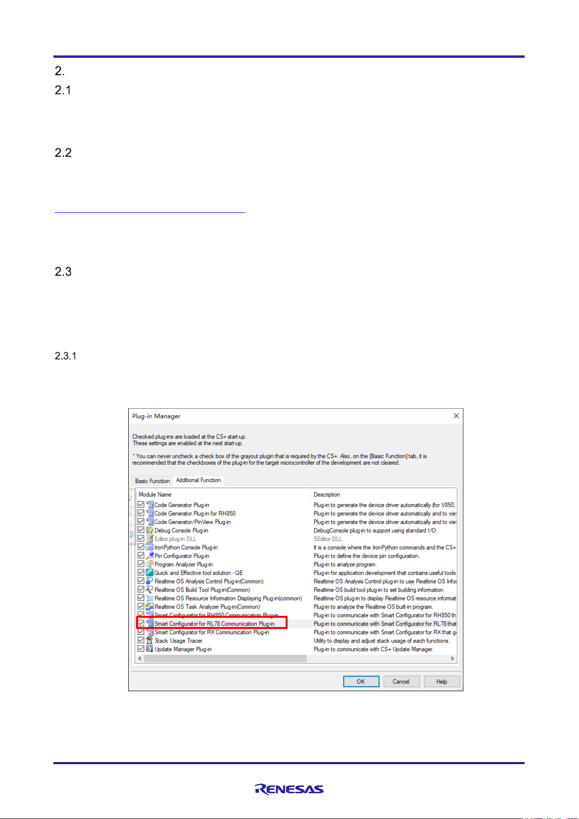
Checking the Plug-in Settings
Select [Plug-in Manager] from [Tool] of CS+ menu and confirm that there is a tick against “Smart
Configurator for RL78 Communication Plug-in”. Tick it if it is not.
Figure 2-1. Plug-in Manager
R20AN0580EC0100 Rev.1.00 Page 5 of 60
Apr.01.21
Page 6
RL78 Smart Configurator User's Guide: CS+
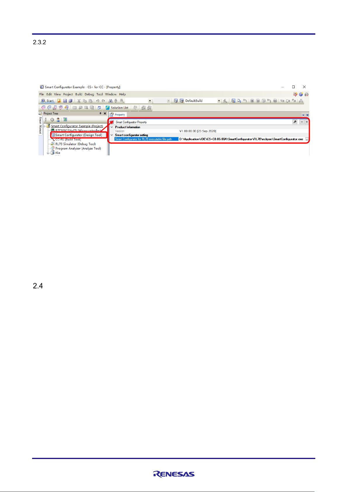
Checking the Setting of the Execution Path
[Smart Configurator (Design Tool)] is displayed under [Project name (Project)] in the Project Tree when you
open the CS+ project for the target device of the Smart Configurator.
Click on [Smart Configurator (Design Tool)], and the Smart Configurator Property panel is displayed.
Figure 2-2. Displaying the Property
“Smart Configurator for RL78 executable file path” shows the executable file of the Smart Configurator. The
following path is set when the Smart Configurator is installed with the default setting (where “CS+” and
“SmartConfigurator” are in the same level).
32-bit environment:
“C:¥Program Files¥Renesas Electronics¥SmartConfigurator¥RL78¥eclipse¥SmartConfigurator.exe”
64-bit environment:
“C:¥Program Files (x86)¥Renesas Electronics¥SmartConfigurator¥RL78¥eclipse¥SmartConfigurator.exe”
When manually specifying the path of the executable file, “Smart Configurator for RL78 executable file path”
can be set as either a relative or an absolute path.
Uninstalling the Smart Configurator
If you wish to uninstall the Smart Configurator, select “Smart Configurator for RL78” and “CS+ Smart
Configurator Communication Plugins for RL78” from [Apps & features] in your PC’s Windows Settings Apps
control panel and uninstall them.
R20AN0580EC0100 Rev.1.00 Page 6 of 60
Apr.01.21
Page 7
RL78 Smart Configurator User's Guide: CS+
Operations in CS+
Operations in the Smart Configurator
Starting CS+
Creating and loading a CS+ project
Starting the Smart Configurator
Setting of peripheral modules
Generating source code
Creating user programs
Building
Execution and debugging
Setting of pins
Refer to section 3.2, Starting
Refer to chapter 7, Creating User
Refer to chapter 4, Setting of
Peripheral Modules.
Refer to section 4.5, Pin
Refer to chapter 6,
Device information
Toolchain information
Registering source files
Generating reports
Refer to chapter 9,
Setting of interrupts
Refer to section 4.6, Interrupt
Settings
Operating the Smart Configurator
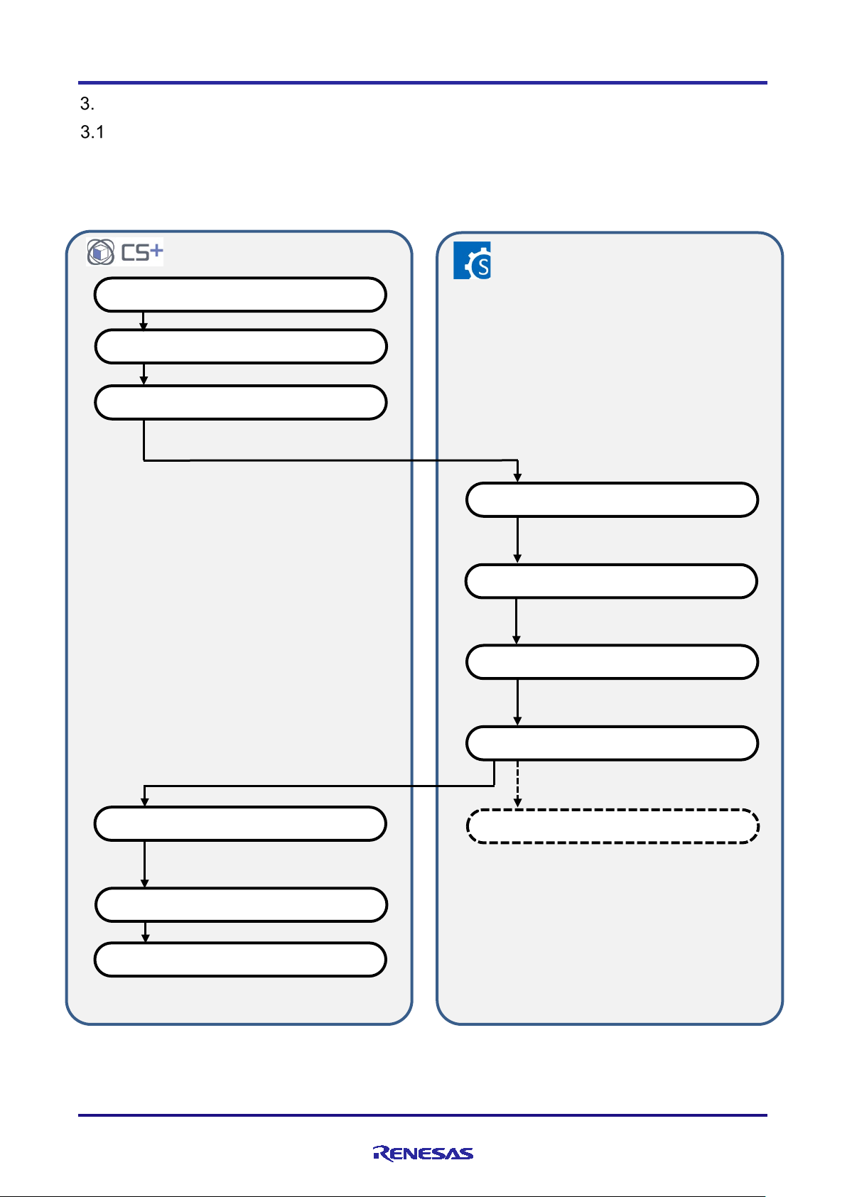
Procedure for Operations
Figure 3-1 shows the procedure for using the Smart Configurator to generate files for setting up peripheral
modules, and to use them in building after registration with CS+. Refer to the related documents on CS+ for
the operation of CS+.
the Smart Configurator.
Settings
Generating Source Code.
Programs.
R20AN0580EC0100 Rev.1.00 Page 7 of 60
Apr.01.21
Generating Reports.
Figure 3-1. Procedure for Operations
Page 8
RL78 Smart Configurator User's Guide: CS+
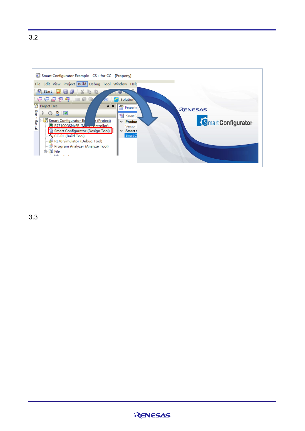
Starting the Smart Configurator
Double-click on [Smart Configurator (Design Tool)] under [Project name (Project)] in the Project Tree of CS+
to start the Smart Configurator. You do not need to select a device or toolchain for the Smart Configurator,
since the settings of the project for CS+ are passed over to the Smart Configurator.
Figure 3-2 Activation of Smart Configurator
Note: The settings of CS+ are not passed over to the Smart Configurator in the following cases: when the Smart
Configurator is activated from its executable file, when a new project is created from [File] menu of the Smart
Configurator, or when an existing file from the Smart Configurator is opened.
File to be Saved as Project Information
The Smart Configurator saves the setting information such as the target MCU for the project, build tool,
peripheral modules, and pin functions in a project file (*.scfg), and refers to this information.
When the Smart Configurator is activated from CS+, the project file from the Smart Configurator is saved in
“project name.scfg”, which is at the same level as the project file (*.mtpj) of CS+.
R20AN0580EC0100 Rev.1.00 Page 8 of 60
Apr.01.21
Page 9
RL78 Smart Configurator User's Guide: CS+
(1)
(2)
(3)
(4)
(5)
(6)
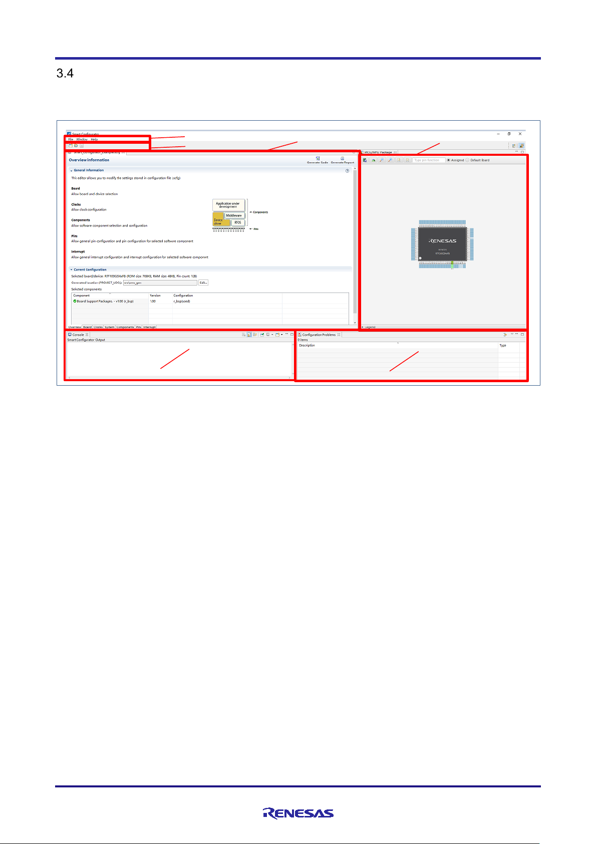
Window
The main window is displayed when the Smart Configurator is started. The configuration of the window is
shown in Figure 3-3, Main Window.
(1) Menu bar
(2) Main toolbar
(3) Smart Configurator view
(4) MCU Package view
(5) Console view
(6) Configuration Problems view
Figure 3-3 Main Window
R20AN0580EC0100 Rev.1.00 Page 9 of 60
Apr.01.21
Page 10
RL78 Smart Configurator User's Guide: CS+
Menu
Details
displayed.
Save
Saves a project with the same name.
handed over from CS+.
Exit
Execution of the Smart Configurator is terminated.
Window
Preference
Show View
The dialog box [Show view], which is used to set the view of the window, is displayed.
Help
Help Contents
The help menu is displayed.
Home Page
The home page is opened.
Release Notes
The release note is opened.
Tool News
The tool news is opened.
API Manual
The API manual is opened.
About
The version information is displayed.
Toolbar button
Related menu item
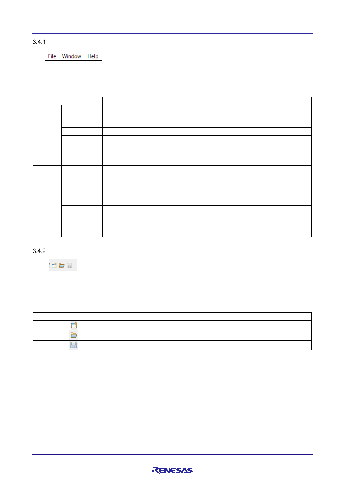
Main Menu
Table 3-1, Main Menu Items, lists the items of the main menu.
Table 3-1. Main Menu Items
File New The dialog box [New Smart Configurator File], which is used to create a new project, is
Open The dialog box [Open], which opens an existing project, is displayed.
Restart Smart Configurator is restarted.
Do not use this menu item in general, as it leads to deletion of the project settings
The dialog box [Preference], which is used to specify the properties of the project, is
displayed.
Toolbar
Some functions of the main menu are allocated to the buttons on the toolbar. Table 3-2, Toolbar Buttons and
Related Menu Items, shows the description of those tool buttons.
Table 3-2. Toolbar Buttons and Related Menu Items
[File] → [New]
[File] → [Open]
[File] → [Save]
R20AN0580EC0100 Rev.1.00 Page 10 of 60
Apr.01.21
Page 11
RL78 Smart Configurator User's Guide: CS+
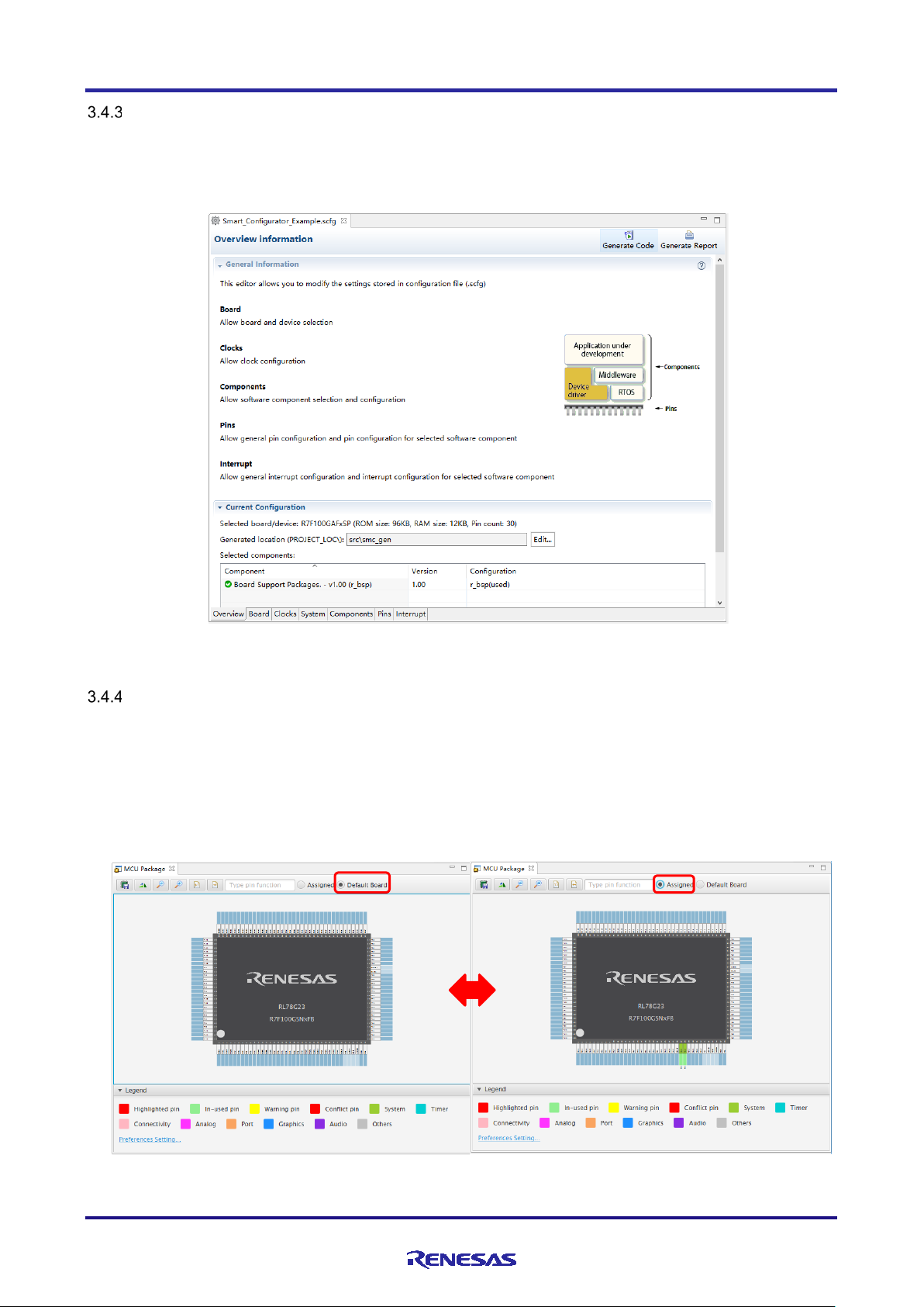
Smart Configurator View
The Smart Configurator view consists of seven pages: [Overview], [Board], [Clocks], [System],
[Components], [Pins], and [Interrupts]. Select a page by clicking on a tab; the displayed page will be
changed.
Figure 3-4. Smart Configurator View
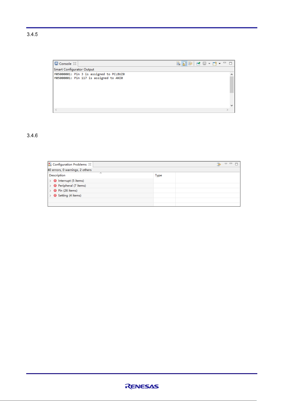
MCU Package View
The states of pins are displayed on the figure of the MCU package. The settings of pins can be modified from
here.
Two types of package view can be switched between [Assigned] and [Default Board]. [Assigned] displays the
assignment status of the pin setting, and [Default Board] displays the initial pin setting information of the
board. The initial pin setting information of the board is the pin information of the board selected by [Board:]
on the [Board] page (refer to "4.1.2 Selecting the Board").
Figure 3-5
R20AN0580EC0100 Rev.1.00 Page 11 of 60
Apr.01.21
. MCU Package View
Page 12
RL78 Smart Configurator User's Guide: CS+
Console View
The Console view displays details of changes to the configuration made in the Smart Configurator or MCU
Package view.
Figure 3-6. Console View
Configuration Problems View
The Configuration Problems view displays the details of conflicts between driver used interrupts, configured
peripherals, used pins, used settings.
Figure 3-7. Configuration Problems View
R20AN0580EC0100 Rev.1.00 Page 12 of 60
Apr.01.21
Page 13
RL78 Smart Configurator User's Guide: CS+
Button
Operation explanation
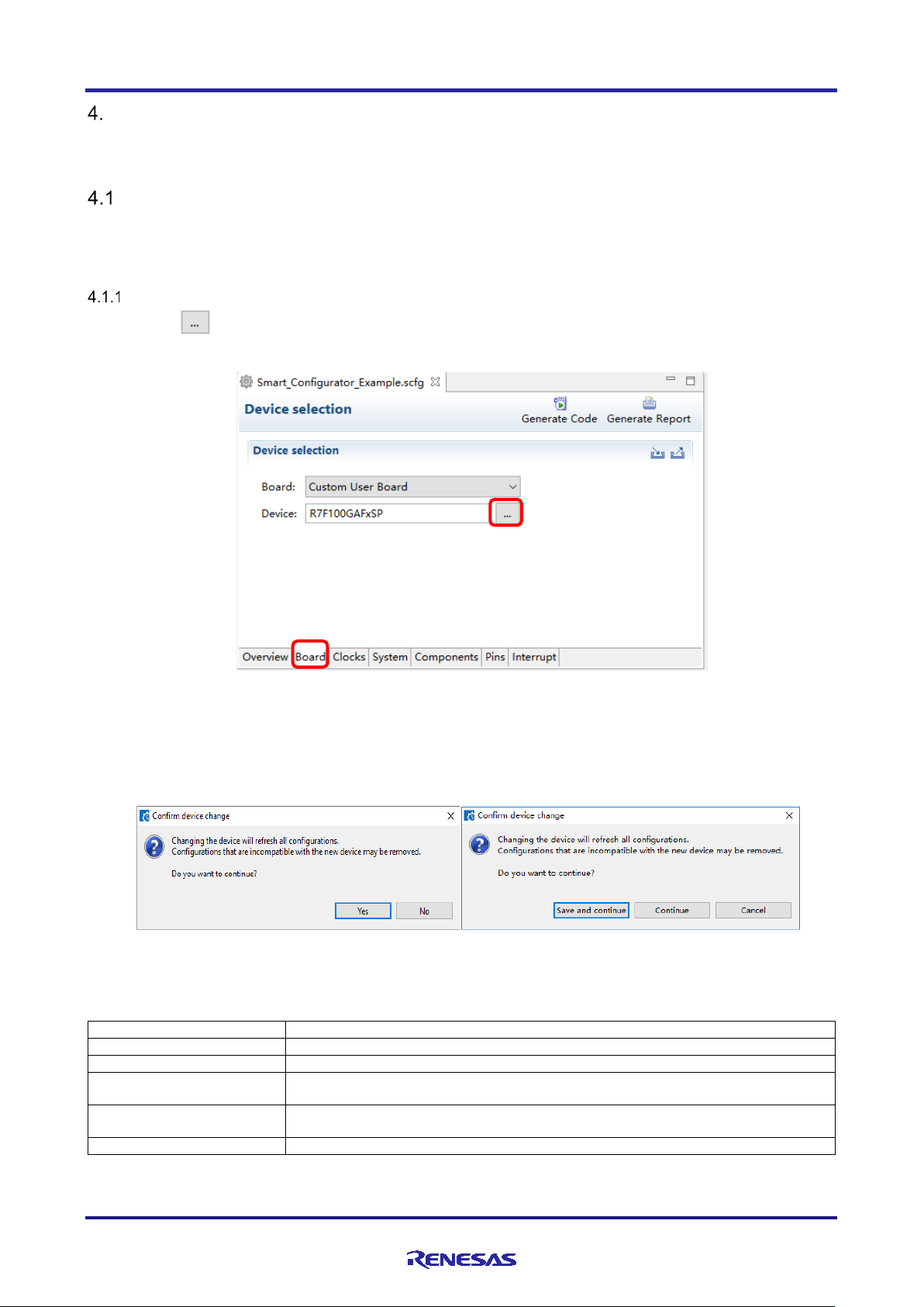
Yes
Change to the selected device.
No
It does not change the device.
Save and continue
(Note*1)
After saving the current configuration contents to the configuration file, change to the
selected device.
Continue
(Note*1)
Changes to the selected device without saving the current configuration contents to
the configuration file.
Cancel
(Note*1)
It does not change the device.
Setting of Peripheral Modules
You can select peripheral modules from the Smart Configurator view.
Board Settings
You can change the board and device on the [Board] page. For information on changing the device of the
project, refer to the CS+ User's Guide.
Selecting the Device
Click on the [ ] button to select a device.
Figure 4-1. Selecting the Device
The following message is displayed when changing the device. For each button operation, refer to "Table
4-1, Device Change Confirmation Operation List".
Figure 4-2. Confirm Device Change
Table 4-1. Device Change Confirmation Operation List
Note *1: Smart Configurator view is marked with dirty *.
Note *2: Device change is not reflected to the device (micro controller) of CS+ project.
R20AN0580EC0100 Rev.1.00 Page 13 of 60
Apr.01.21
Page 14
RL78 Smart Configurator User's Guide: CS+
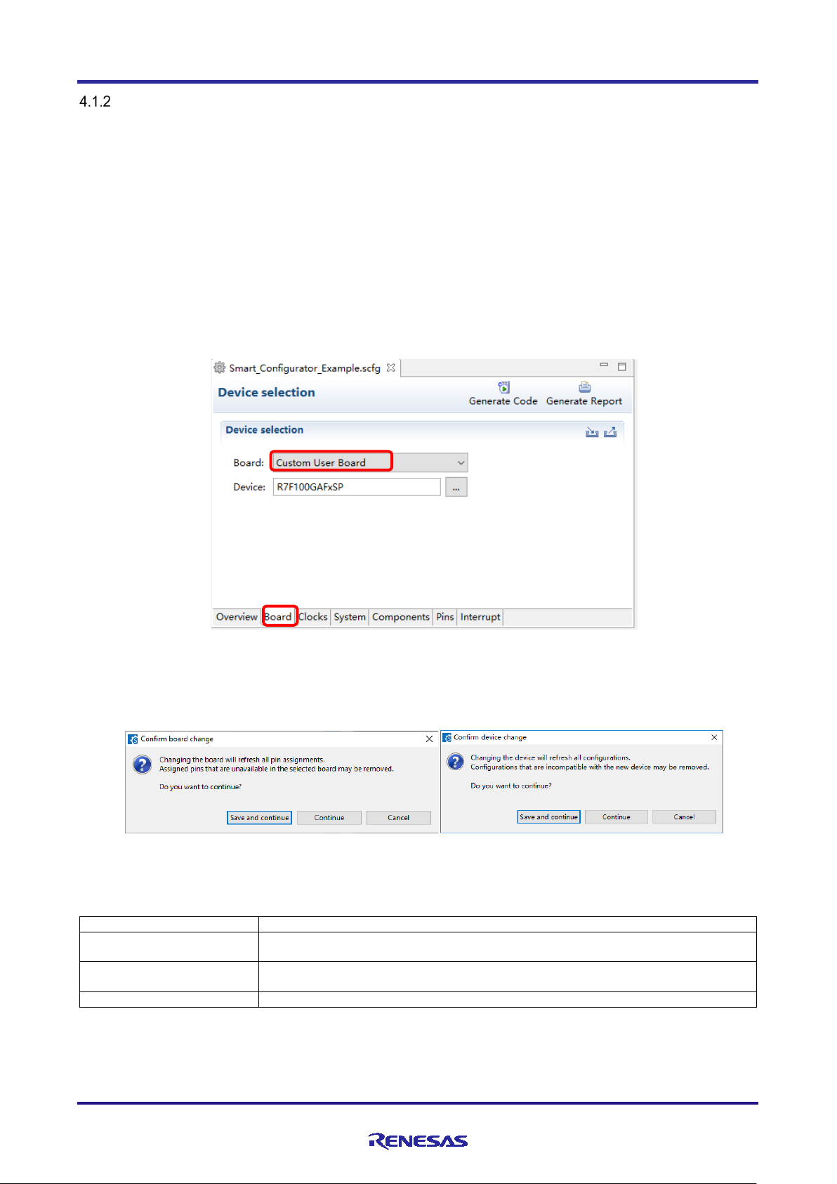
Button
Operation explanation
Save and continue
After saving the current configuration contents to the configuration file, change to the
selected device.
Continue
Changes to the selected device without saving the current configuration contents to
the configuration file.
Cancel
It does not change the device.
Selecting the Board
By selecting a board, the following settings can be changed at one time.
• Pin assignment (Initial pin setting)
• Frequency of the main clock
• Frequency of the subsystem clock
• Target device
The board setting information is defined in the Board Description File (.bdf).
The .bdf file of Renesas made board (e.g. Renesas Starter Kit) can be downloaded from website and
imported.
In addition, by downloading the .bdf file provided by the alliance partner from website and importing it, it is
possible to select alliance part boards.
Figure 4-3. Selecting the Board
If you change the board, the message will be displayed. For each button operation, refer to "Table 4-2, Board
Change Confirmation Operation List".
Figure 4-4. Confirm Board Change
Table 4-2. Board Change Confirmation Operation List
Note: Depending on the board selected, the device will change, Device change is not reflected to the target device of
CS+ project.
R20AN0580EC0100 Rev.1.00 Page 14 of 60
Apr.01.21
Page 15
RL78 Smart Configurator User's Guide: CS+
(1)
(2)
(1)
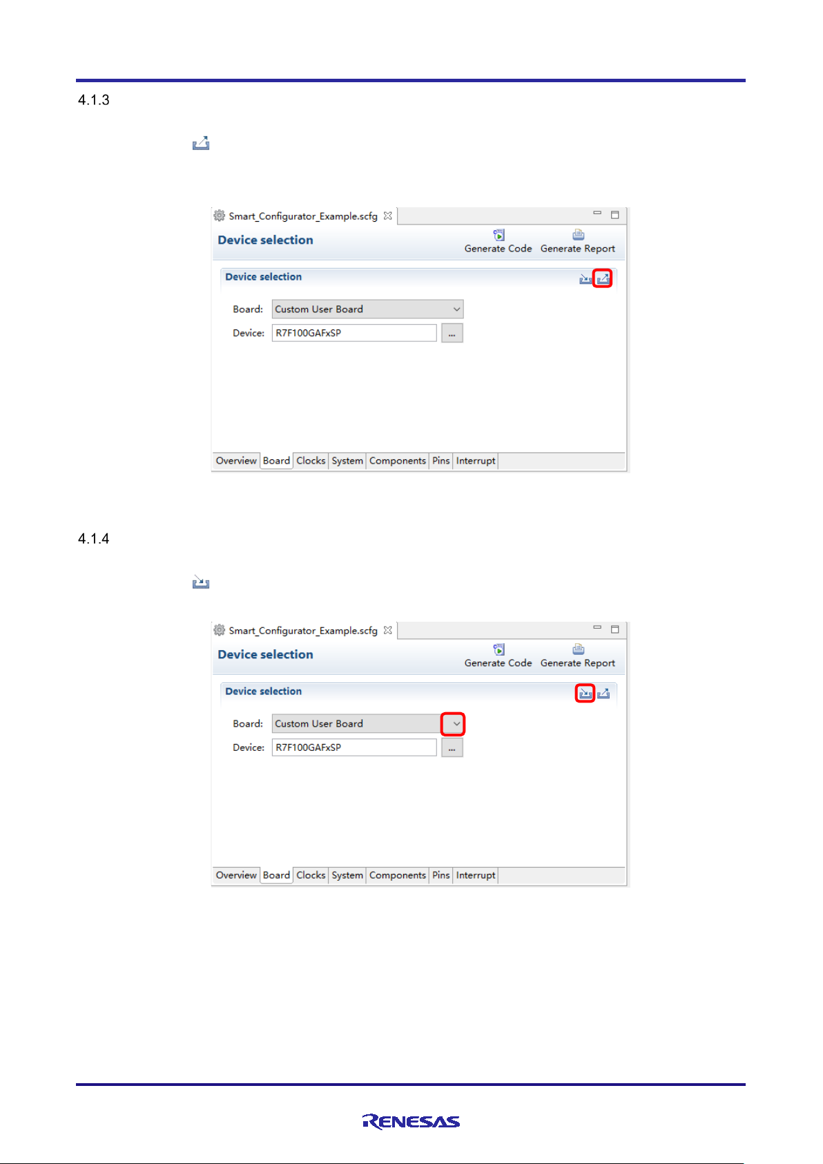
Exporting Board Settings
Follow the procedure below to export the board settings.
(1) Click on the [ (Export board setting)] button on the [Board] page.
(2) Select the output location and specify a name (Display Name) for the file to be exported.
Figure 4-5. Exporting Board Settings (bdf Format)
Importing Board Settings
Follow the procedure below to import board settings.
(1) Click on the [ (Import board setting)] button and select a desired bdf file.
(2) The board of the imported settings is added to the board selection menu.
Figure 4-6. Importing Board Settings (bdf Format)
Once a board setting file is imported, the added board is also displayed in the board selection menu of other
projects for the same device group.
R20AN0580EC0100 Rev.1.00 Page 15 of 60
Apr.01.21
Page 16
RL78 Smart Configurator User's Guide: CS+
(1)
(2)
(3)
(4)
(4)
(4)
(4)
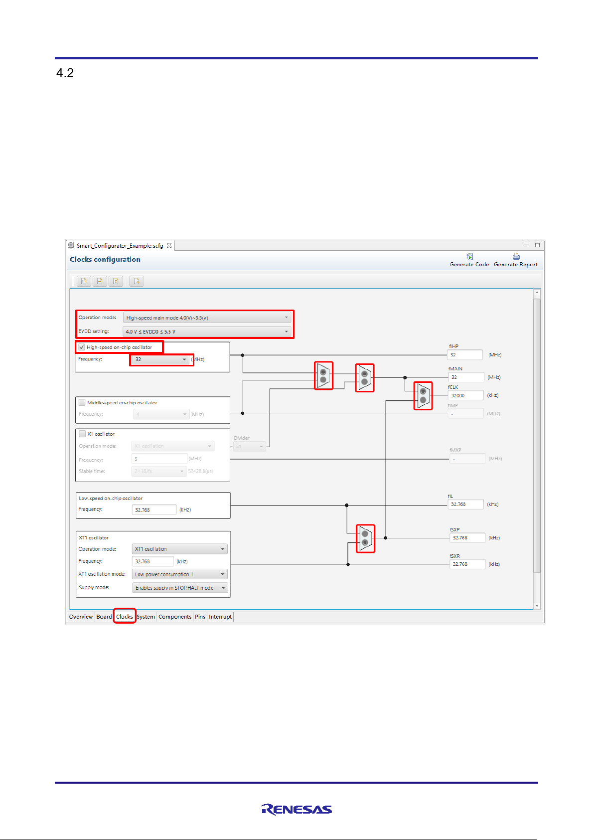
Clock Settings
You can set the system clock on the [Clocks] page. The settings made on the [Clocks] page is used for all
drivers.
Follow the procedure below to modify the clock settings.
(1) Specify the operation mode and EVDD setting.
(2) Select the clocks required for device operations on the board (the high-speed on-chip oscillator is
selected by default).
(3) Specify the frequency of each clock in accordance with the board specifications (note that the frequency
is fixed for some internal clocks).
(4) For the multiplexer symbol, select the clock source for the output clocks.
Figure 4-7. [Clocks] Page
R20AN0580EC0100 Rev.1.00 Page 16 of 60
Apr.01.21
Page 17
RL78 Smart Configurator User's Guide: CS+
(2)
(1)
(3)
(4)
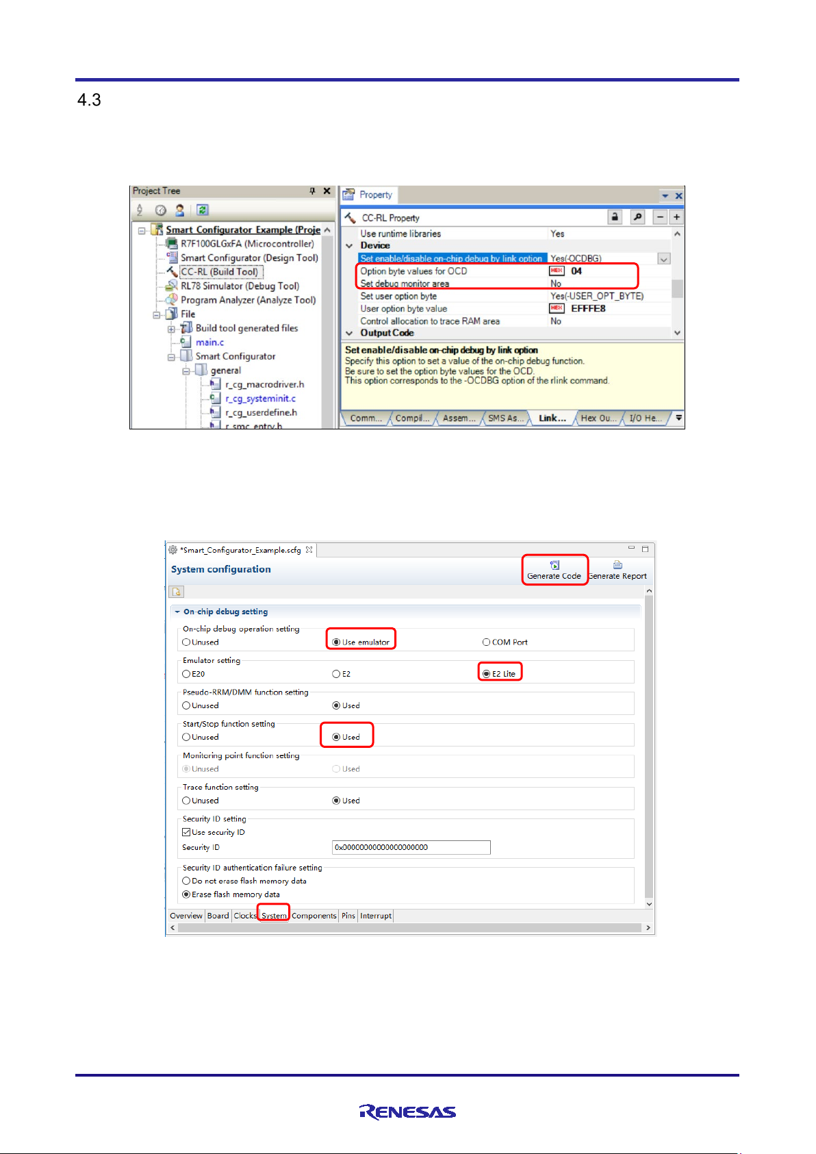
System Settings
You can set the on-chip debug setting on the [System] page. This setting is reflected in the CS + build option
settings via the communication plugin.
For example, below figure shows the default CS+ link option settings:
Figure 4-8. CS+ Default Link Options View
After you click on [System] page of Smart Configurator, make desired setting as in below figure for
illustration:
Figure 4-9. Smart Configurator [System] Page Setting
Note: The security ID setting is reflected in the security ID of Build Tool Common Options.
Other items are not reflected, so you need to set the Build Tool property in the same way.
R20AN0580EC0100 Rev.1.00 Page 17 of 60
Apr.01.21
Page 18
RL78 Smart Configurator User's Guide: CS+
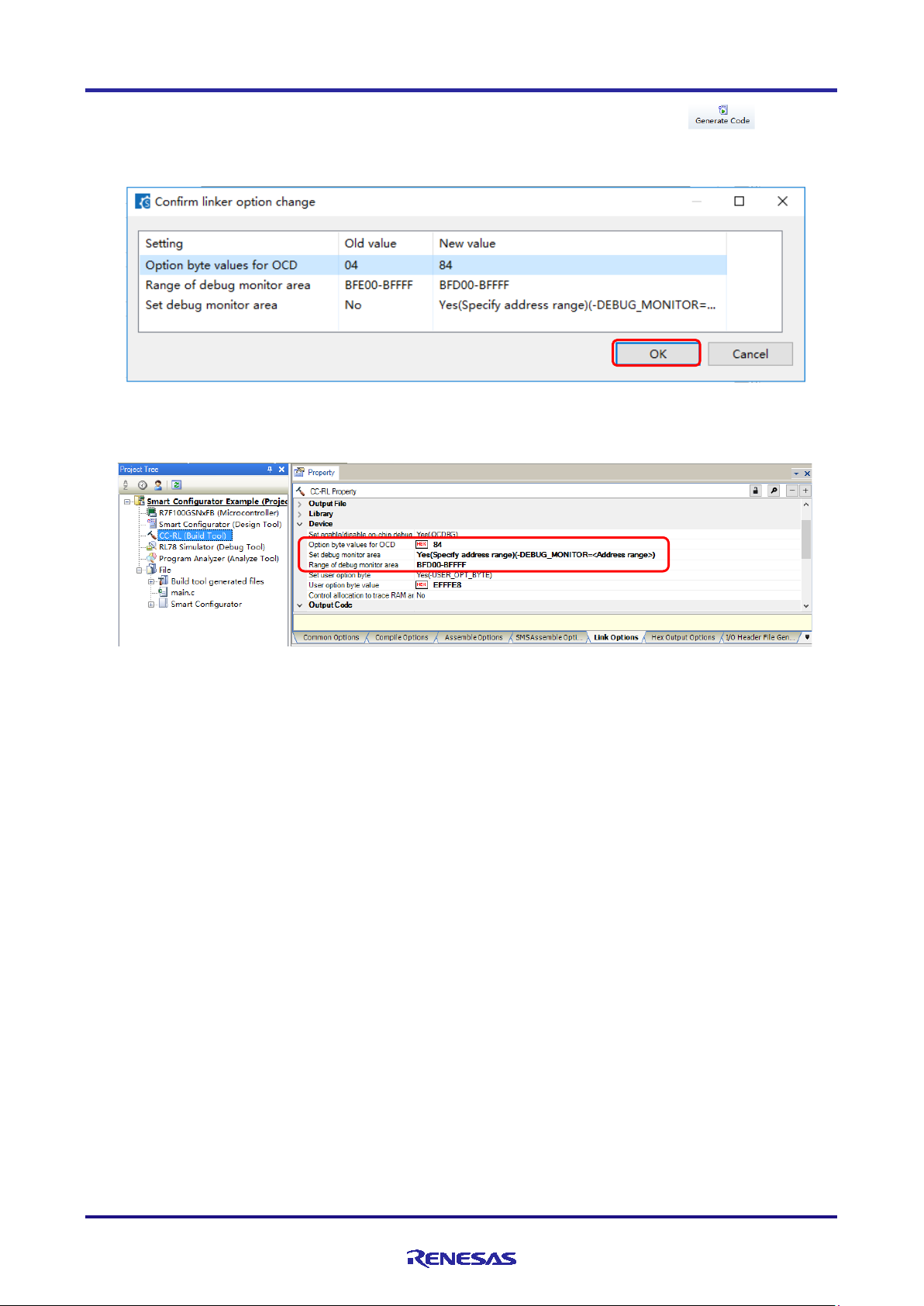
Please follow steps from (1) to (3) to make setting on [System] page, after that click on [ Generate
Code] button as in step (4), a dialog window will be prompted out as in below figure, to confirm with you for
the linker option update in CS+ IDE:
Please click [OK] button in the dialog, go back CS+ to check linker options updated as below:
Note: Depending on the MCU type selection or chip part numbers, these setting values varies. Please refer to the latest
device HUM for the detail setting configuration
Figure 4-10. Confirm Linker Option Dialog
Figure 4-11. CS+ Updated Link Options View
.
R20AN0580EC0100 Rev.1.00 Page 18 of 60
Apr.01.21
Page 19
RL78 Smart Configurator User's Guide: CS+
Tree view for components
(1)
(2)
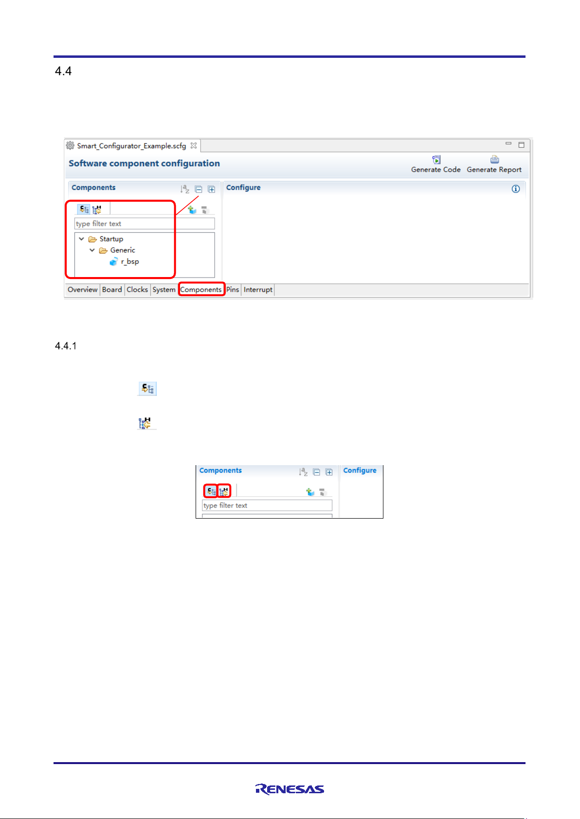
Component Settings
CG drivers, Graphical Configurator and RL78 Software Integration System module can be combined as
software components on the [Components] page. Added components are displayed in the tree view at the
left of the page.
Figure 4-12. [Components] Page
Switching Between the Component View and Hardware View
The Smart Configurator provides two tree view: Component View and Hardware View. You can Switch two
view by clicking the following icons:
(1) Click on the [ (Component View)] icon. The tree view will display the components by component
category.
(2) Click on the [ (Hardware View)] icon. The tree view will display the components in a hardware
resource hierarchy.
Figure 4-13. Switching to the Hardware View
R20AN0580EC0100 Rev.1.00 Page 19 of 60
Apr.01.21
Page 20

RL78 Smart Configurator User's Guide: CS+
a-1.
a-2.
a-3.
a-4.
Adding a Software Component
The Smart Configurator provides two methods for adding a new component:
(a) Click on the [ (Add component)] icon.
(b) On Hardware Tree, double-click on a hardware resource node.
The following describes the procedure for adding a component by clicking on the [ (Add component)]
icon.
a-1. Click on the [ (Add component)] icon.
Figure 4-14. Adding a Component
a-2. Select a component from the list in the [Software Component Selection] page of the [New Component]
dialog box (e.g. A/D Converter).
a-3. Check that [Type] for the selected component is [Code Generator].
a-4. Click on [Next].
Figure
4-15. Adding a Code Generator Component
R20AN0580EC0100 Rev.1.00 Page 20 of 60
Apr.01.21
Page 21

RL78 Smart Configurator User's Guide: CS+
a-5.
a-7.
a-6.
b-2.
b-3.
b-1.
a-5. Specify an appropriate configuration name in the [Add new configuration for selected component] page
of the [New Component] dialog box or use the default name (e.g. Config_ADC).
a-6. Select a hardware resource or use the default resource (e.g. ADC).
a-7. Click on [Finish].
Figure 4-16. Adding a Component
To add a component on Hardware Tree directly, you can use the following procedure:
b-1. Click on the [ (Hardware View Menu)] icon. The tree will display in a hardware resource hierarchy.
b-2. Double-click on a hardware resource node (e.g. A/D Converter) to open the [New Component] dialog
box.
b-3. Select a component from the list (e.g. A/D Converter) to add a new configuration.
b-4. Follow the same procedure as above “adding a component by clicking adding icon” step a-3 to a-7.
Figure 4-17. Adding a Code Generator Component to the Hardware View
R20AN0580EC0100 Rev.1.00 Page 21 of 60
Apr.01.21
Page 22

RL78 Smart Configurator User's Guide: CS+
(2)
(1)
Removing a Software Component
Follow the procedure below to remove a software component from a project.
(1) Select a software component from the Components tree.
(2) Click on the [ (Remove component)] icon.
Figure 4-18. Removing a Software Component
The selected software component will be removed from the Components tree.
Source files generated for this component are not removed from the CS+ project tree. After generating
source code by clicking [ (Generate Code)] icon, the source files generated for removed
component will be removed from the CS+ project tree.
R20AN0580EC0100 Rev.1.00 Page 22 of 60
Apr.01.21
Page 23

RL78 Smart Configurator User's Guide: CS+
(1)
(2) b.
(2) c.
(2) d.
(2) a.
Setting a Code Generator Component
Follow the procedure below to set up a Code Generator configuration.
(1) Select a Code Generator configuration from the Components tree (e.g. A/D Converter).
(2) Configure the driver in the [Configure] panel to the right of the Components tree. The following steps
and figure show an example.
a. Select [10 bits] under [Resolution setting].
b. Select [Software trigger no wait mode] under [Trigger mode setting].
c. Select [ANI0] for [A/D channel selection].
d. Select [2048/fCLK] for [Conversion time].
Figure 4-19. Setting of a Code Generator Driver
Generation of a code in accordance with each Code Generator configuration is enabled by default.
Right-clicking on a Code Generator configuration and then selecting the [ ] icon changes the
icon to [ ] and disables code generation for the Code Generator configuration.
To enable code generation again, click on the [ ] icon and change it to [ ].
R20AN0580EC0100 Rev.1.00 Page 23 of 60
Apr.01.21
Page 24

RL78 Smart Configurator User's Guide: CS+
(1)
(2)
(3)
(4)
Changing the Resource for a Code Generator Component
The Smart Configurator enables you to change the resource for a Code Generator component (e.g. from
TAU0_1 to TAU0_3). Compatible settings can be ported from the current resource to the new resource
selected.
Follow the procedure below to change the resource for an existing software component.
(1) Right-click on a Code Generator configuration (e.g. Config_TAU0_1).
(2) Select [Change resource] from the context menu.
Figure 4-20. Changing the Resource
(3) Select a new resource (e.g. TAU0_3) in the [Resource Selection] dialog box.
(4) The [Next] button will be active, click on it.
Figure 4-21. Components Page – Selecting a New Resource
R20AN0580EC0100 Rev.1.00 Page 24 of 60
Apr.01.21
Page 25

RL78 Smart Configurator User's Guide: CS+
(6)
(8)
(7)
(5) Configuration settings will be listed in the [Configuration setting selection] dialog box.
(6) Check the portability of the settings.
(7) Select whether to use the listed below or default settings.
(8) Click on [Finish].
Figure 4-22. Checking the Settings of the New Resource
The resource is automatically changed (e.g. changed from INTTM01 to INTTM03).
Figure 4-23. Resource Changed Automatically
R20AN0580EC0100 Rev.1.00 Page 25 of 60
Apr.01.21
Page 26

RL78 Smart Configurator User's Guide: CS+
(9)
(10)
To change the configuration name, follow the procedure below.
(9) Right-click on the Code Generator configuration.
(10) Select [Rename] to rename the configuration (e.g. change Config_TAU0_1 to Config_TAU0_3).
Figure 4-24. Renaming the Configuration
Setting SNOOZE Mode Sequencer (SMS) Component
SNOOZE Mode Sequencer (SMS) component is a new component type as “Graphical Configurator”, it is list
and can be selected to use directly in default component list.
Figure 4-25. Add SNOOZE Mode Sequencer
R20AN0580EC0100 Rev.1.00 Page 26 of 60
Apr.01.21
Page 27

RL78 Smart Configurator User's Guide: CS+
Area
Description
comparison & branching and 1-byte transfer.
(2) Toolbar
Zoom in.
Zoom out.
Display the SMS data management dialog and manage the variables to be used.
Import the SMS sequence. You can use some sample sequences by clicking this icon.
Export the SMS sequence.
Update the SMS data file.
Displays the information of the SMS data file.
(3) Start trigger selection
Select a startup trigger.
(4) Resource status
It shows registers and the number of instructions used.
(5) Canvas area
Place the SMS block and create the sequence.
(6) SMS console
Displays message for unavailable configurations.
(1)
(2)
(3)
(4)
(5)
(6)
A GUI of Graphical Configurator is displayed in below SMS figure, it is more graphically compared with Code
Generator. You can Drag and Drop and configure the block which you want to use.
Figure 4-26.
SNOOZE Mode Sequencer (SMS) GUI
Table 4-3. SMS GUI area description
(1) Block elements View the available blocks for SMS.
A block is a part for forming a sequence (function), and includes A/D voltage acquisition,
R20AN0580EC0100 Rev.1.00 Page 27 of 60
Apr.01.21
Page 28

RL78 Smart Configurator User's Guide: CS+
(1)
(3)
(4)
(6)
(2)
(5)
Follow the procedure below to set up SMS block:
(1) Select a block from Block elements list (e.g. CSI Master receive).
(2) Drag “CSI Master receive” block to SMS canvas between Start block and Finish block where the drop
location doesn’t show the indicator of .
(3) You can configure the block by double click to pop the “CSI Master receive setting” property setting
dialog.
(4) You can specify the setting in the “CSI Master receive setting” property dialog.
(5) Open “Data Management” setting, you can edit the receive data.
(6) When you correctly configure the color of bottom right corner will change from red to green.
(7) You can add some blocks, drag and drop to adjust the sequence.
Figure 4-27. S
R20AN0580EC0100 Rev.1.00 Page 28 of 60
Apr.01.21
MS Block Configure
Page 29

RL78 Smart Configurator User's Guide: CS+
(1)
(2)
(3)
Update SMS Data Files
Follow the procedure below to update SMS data file (Block, Sequence) to the latest version. You can use
new blocks and sequences by updating.
(1) Click on SMS GUI button [Update SMS data files] to check if SMS data file have the newer version and
download automatically from the web.
(2) Waiting for the operation finished.
(3) Finished the latest version update.
Figure 4-28. SMS Data File Download
R20AN0580EC0100 Rev.1.00 Page 29 of 60
Apr.01.21
Page 30

RL78 Smart Configurator User's Guide: CS+
(1)
(2)
(3)
(2)
Logic Event Link Controller (ELCL) Modules Download
The Software Component type for Logic Event Link Controller (ELCL) is Graphical Configurator. ELCL
modules can be added from component list in New Component dialog. If you want to use other ELCL
modules not included in Component list, you can click on [Download ELCL modules] link in New Component
dialog to check and download more ELCL modules:
Figure 4-29. New ELCL Modules Download
After download, all ELCL modules are auto added to component list:
Figure 4-30. Add ELCL modules
R20AN0580EC0100 Rev.1.00 Page 30 of 60
Apr.01.21
Page 31

RL78 Smart Configurator User's Guide: CS+
(2) a
(2) b
(2) c
(3)
Setting an ELCL Component
Follow the procedure below to set up an ELCL module.
(1) Select an ELCL module from Software Component Selection list (e.g. ELCL slave select pin function).
(2) Configure the driver in the [Configure] panel. The following steps and figure show an example.
a. Select the input signal under [Input signal selector] UI part.
b. Select the logic block under [Event controller (link processor)] UI part.
c. Select the output signal under [Output signal selector] UI part.
(3) If you want for more details about current ELCL module usage, you can click the
[ELCL_slave_select_pition.pdf] link to open the application notes for check.
Figure 4-31. Configure an ELCL Module
R20AN0580EC0100 Rev.1.00 Page 31 of 60
Apr.01.21
Page 32

RL78 Smart Configurator User's Guide: CS+
Downloading RL78 Software Integration System Modules
RL78 Software Integration System modules are another software component type which can provide simple
view for you to make driver/middle/application SW configuration and generate the code. The available RL78
Software Integration System modules can be downloaded from Renesas web. You first click on [ (Add
component)] as in Figure 4-14 to open a dialog, select the corresponding download entry link to start the
download.
Figure 4-32. RL78 Software Integration System Download Link
The downloaded RL78 Software Integration System modules location was specified by Smart Configurator
module download preference setting which can be checked and set by click main menu: [Window] →
[Preference] → [Renesas] → [Module download] → [Location(RL78)].
Figure 4-33. RL78 Software Integration System Modules Download Location
R20AN0580EC0100 Rev.1.00 Page 32 of 60
Apr.01.21
Page 33

RL78 Smart Configurator User's Guide: CS+
Setting a RL78 Software Integration System Module
After RL78 Software Integration System module is downloaded and added to New Component List, it can be
selected in your project with providing the property view style configuration and code generation feature.
Changing Version of BSP Configuration
The following describes the procedure for version change of BSP configuration.
(1) From the component tree, right-click the r_bsp component whose version you want to change.
Figure 4-34. Version Change of BSP Configuration
(2) Select [Change Version ...] from the context menu.
(3) In the [Change Version] dialog box, select the version you want to change. If you select a version that
the device does not support, [Selected version doesn’t support current device or toolchain] will be
displayed, so select the corresponding version.
(4) Click [Next].
Figure 4-35. Select Version of BSP Component
R20AN0580EC0100 Rev.1.00 Page 33 of 60
Apr.01.21
Page 34

RL78 Smart Configurator User's Guide: CS+
(5) By version change, a list of setting items to be changed is displayed. Confirm that there is no problem
and click the [Finish].
Figure 4-36. Confirm Setting Change Item
(6) As [Confirm to change version and proceed to generate code] Is displayed, if you do not have any
problem, click [Yes].
Figure 4-37. Confirm Version Change
(7) The BSP component version is change and code generation is executed automatically.
Note: When you’ve generated BSP code by old version, after change BSP version, the code may not be replaced by
new code. You can change the [Generating code] property in 4.4.13 Configure General Setting of Component
R20AN0580EC0100 Rev.1.00 Page 34 of 60
Apr.01.21
Page 35

RL78 Smart Configurator User's Guide: CS+
Configure General Setting of Component
You can change the general setting of the component such as location and dependency. If you want to
change it, click the [Configure general settings...] link on the [Software Component Selection] page displayed
in the [New Component] dialog (Figure 4-15 Adding a Code Generator Component), and display the
[Preferences] dialog.
Figure 4-38. Configure General Setting of Component
Notes:
1. The code generation has two options: [Do nothing if component exists] and [Overwrite existing component].
[Do nothing if component exists] is the default selection, when select it, a code file, which has the same name
as the new one, will not be replaced. After changing version, if you want to the code can be replaced, please
select [Overwrite existing component].
Figure 4-39. [Generation code] Change
R20AN0580EC0100 Rev.1.00 Page 35 of 60
Apr.01.21
Page 36

RL78 Smart Configurator User's Guide: CS+
Notes:
2. If you want to only generate initialization API function, you can change to [Output only initialization API
function] option in below figure. So that only void R_{ConfigurationName}_Create (void), void
R_{ConfigurationName}_Create_UserInit (void) in *.h *, *c * are generated. If you change back to default option
setting: [Output all API functions according to the setting], then all API functions will be generated again.
Figure 4-40. [RL78 API function output] Change
3. If the version of the module and its dependency do not match, a warning message W04020011 is displayed. If
you check the revision history of the module and its dependencies and you do not need to change the module
you are using, you can ignore this warning. To clear this warning, select [Do not check for dependent
component] in the [Checking dependency] list box in component preferences, then click [OK].
Figure 4-41. [Checking dependency] Change
R20AN0580EC0100 Rev.1.00 Page 36 of 60
Apr.01.21
Page 37

RL78 Smart Configurator User's Guide: CS+
Display switching
Pin Settings
The [Pins] page is used for assigning pin functions. You can switch the view by clicking on the [Pin Function]
and [Pin Number] pages. The [Pin Function] list shows the pin functions for each of the peripheral functions,
and the [Pin Number] list shows all pins in order of pin number.
Figure 4-42. [Pins] Page ([Pin Function])
Figure 4-43. [Pins] Page ([Pin Number])
R20AN0580EC0100 Rev.1.00 Page 37 of 60
Apr.01.21
Page 38

RL78 Smart Configurator User's Guide: CS+
(1)
(3)
(3)
Changing the Pin Assignment by PIOR Function
PIOR “Filter Function” is a powerful feature to help you manage pin function settings, re-configure pin
function settings or check pin function conflicts.
Follow the procedure below to change the assignment by PIOR function.
(1) Type “pior1” in the tool text input box, all pin functions which related to PIOR1 will be listed out.
(2) If you change one of pin assignment, all pin function assignments which related to PIOR1 will be re-
assigned automatically.
(3) The pin error messages may display in [Remark] column and [Configuration Problems view].
(4) You need to re-configure pin assignment.
Figure 4-44. PIOR Filter Function
The PIOR setting can be reflected into r_bsp file in:
¥<ProjectDir>¥src¥smc_gen¥r_bsp¥r_config¥ r_bsp_config.h file. If you want to change the PIOR setting
code value, change the assignment of related pin and generate code again.
Figure 4-45. PIOR Code Generation
R20AN0580EC0100 Rev.1.00 Page 38 of 60
Apr.01.21
Page 39

RL78 Smart Configurator User's Guide: CS+
(1)
(2)
(3)
(4)
(5)
Changing the Pin Assignment of a Software Component
The Smart Configurator assigns pins to the software components added to the project. Assignment of the
pins can be changed on the [Pins] page.
This page provides two lists: Pin Function and Pin Number.
Follow the procedure below to change the assignment of pins to a software component in the Pin Function
list.
(1) Click on [ (Show by Hardware Resource or Software Components)] to switch to the component view.
(2) Select the target software component (e.g. Config_INTC).
(3) Click the [Enabled] header to sort by pins used.
(4) In the [Assignment] column or [Pin Number] column on the [Pin Function] list, change the pin
assignment (e.g. change from P12 to P16).
(5) In addition, assignment of a pin can be changed by clicking on the [ (Next group of pins for the
selected resource)] button. Pin that has peripheral function is displayed each time the button is clicked.
Figure 4-46 Pin Settings – Assigning Pins on the [Pin Function] List
The Smart Configurator allows you to enable pin functions on the [Pins] page without linking the current
software component to another. To distinguish these pins from other pins that are used by another software
component, there will be a remark "There is no software initializing this pin" on the list. In this case, no
initialization code will be generated, so add the component.
R20AN0580EC0100 Rev.1.00 Page 39 of 60
Apr.01.21
Page 40

RL78 Smart Configurator User's Guide: CS+
(2)
(3)
(4)
Assigning Pins Using the MCU Package View
The Smart Configurator visualizes the pin assignment in the MCU Package view. You can save the MCU
Package view as an image file, rotate it, and zoom in to and out from it.
Follow the procedure below to assign pins in the MCU Package view.
(1) Zoom in to the view by clicking the [ (Zoom in)] button or scrolling the view with the mouse wheel.
(2) Right-click on the target pin.
(3) Select the signal to be assigned to the pin.
(4) The color of the pins can be customized through [Preference Setting...].
Figure 4-47. Assigning Pins Using the MCU Package View
R20AN0580EC0100 Rev.1.00 Page 40 of 60
Apr.01.21
Page 41

RL78 Smart Configurator User's Guide: CS+
(1)
Exporting Pin Settings
The pin settings can be exported for later reference. Follow the procedure below to export the pin settings.
(1) Click on the [ (Export board setting)] button on the [Pins] page.
(2) Select the output location and specify a name for the file to be exported.
The exported XML file can be imported to another project having the same device part number.
Figure 4-48. Exporting Pin Settings to an XML File
The Smart Configurator can also export the pin settings to a CSV file. Click on the [ (Save the list to .csv
file)] button on the [Pins] page.
Importing Pin Settings
To import pin settings into the current project, click on the [ (Import board setting)] button and select the
XML file that contains the desired pin settings. After the settings specified in this file are imported to the
project, the settings will be reflected in the [Pin configuration] page.
Figure 4-49. Importing Pin Settings from an XML File
Note: The pin setting is reflected, but it is not reflected in the component setting.
R20AN0580EC0100 Rev.1.00 Page 41 of 60
Apr.01.21
Page 42

RL78 Smart Configurator User's Guide: CS+
(2)
(3)
(4)
(5)
Pin Setting Using Board Pin Configuration Information
You can set the initial pin configuration of the board at once. The following describes the procedure for
collective setting of pins.
(1) Select a board setting information except [Custom User Board] in [Board] page. You can refer to 4.1.2
Selecting the Board.
(2) Select [Default Board] in the MCU Package. (The initial pin configuration of the board can be
referred.)
(3) Open the [Pin Configuration] page and click the [Assign default board pins] button.
(4) When [Assign default board pins] dialog opens, click [Select all].
(5) Click [OK].
Figure 4-50. Setting for Initial Pin Configuration
If you do not set pin settings all at once, specify them individually in procedure (3).
Pin Filter Feature
By specifying the filter range on the [Pin Function] page and [Pin Number] page on the [Pins] page, you can
refer to it more easily.
Figure 4-51. Filter for [Pin Function] Page
Figure 4-52. Filter for [Pin Number] Page
R20AN0580EC0100 Rev.1.00 Page 42 of 60
Apr.01.21
Page 43

RL78 Smart Configurator User's Guide: CS+
(2)
(2)
(1)
Interrupt Settings
The [Interrupt] page displays all interrupt by each of the vector numbers. You can check and set the
interrupts of the peripheral modules that have been selected on the [Components] page. When an interrupt
is used in a Code Generator configuration on the [Components] page, the status of the interrupt will be
changed to "Used".
(1) To display the used interrupts only, click on the [ (Show used interrupts)] button.
(2) Group interrupts are collapsed in the interrupt table. Click on the [ (Open)] button to expand the view
and see the interrupts in the group interrupt list.
Figure 4-53. [Interrupts] Page
Changing Interrupt Priority Setting
You can change the interrupt priority level on the [Interrupts] page using the following procedure:
(1) Find the interrupt which you want to change priority setting on this page.
(2) Click the priority cell and select an interrupt priority level from the drop-down list.
Figure 4-54. Interrupt Settings
R20AN0580EC0100 Rev.1.00 Page 43 of 60
Apr.01.21
Page 44

RL78 Smart Configurator User's Guide: CS+
/**********************************************************************
(1)
(3)
(2)
Changing Interrupt Bank Setting
You can change the interrupt bank level on the [Interrupts] page using the following procedure:
(1) Find the interrupt which you want to change bank setting on this page.
(2) Click the [Bank specify] cell and select a bank setting from the drop-down list (There are four levels
[None / 1 / 2 / 3])
(3) If same bank levels are selected for different interrupt, warning mark will be displayed and warning
message is displayed in [Remarks]. You should check and re-set the bank setting.
Figure 4-55. Change Interrupt Bank Setting Example
The interrupt bank setting can be reflected into generated code in component’s {ConfigurationName}_user.c
file.
Pragma directive
***********************************************************************
#pragma interrupt r_Config_INTC_intp0_interrupt(vect=INTP0)
#pragma interrupt r_Config_INTC_intp1_interrupt(vect=INTP1, bank=RB1)
#pragma interrupt r_Config_INTC_intp2_interrupt(vect=INTP2, bank=RB2)
#pragma interrupt r_Config_INTC_intp3_interrupt(vect=INTP3, bank=RB3)
Figure 4-56. Interrupt Bank Setting Example (CS+ Project)
The concrete generated code specification is different for different compilers. You can get more information
in corresponding IDE user guide.
R20AN0580EC0100 Rev.1.00 Page 44 of 60
Apr.01.21
Page 45

RL78 Smart Configurator User's Guide: CS+
Managing Conflicts
When you add a component or configuring a pin or interrupt may cause problems in terms of resource
conflict and missing dependency modules. This information will be displayed in the Configuration Problems
view. You can refer to the displayed information to fix the conflict issues. You can generate code even if
there are conflicts.
Resource Conflicts
When two software components are configured to use the same resource (e.g. ADC), an error mark ( ) will
be displayed in the Components tree.
The Configuration Problems view will display messages on peripheral conflicts to inform the you in which
software configurations peripheral conflicts have been detected.
Figure 5-1. Resource Conflicts
Resolving Pin Conflicts
If there is a pin conflict, an error mark will appear on the tree and [Pin Function] list.
Figure 5-2. Pin Conflicts
R20AN0580EC0100 Rev.1.00 Page 45 of 60
Apr.01.21
Page 46

RL78 Smart Configurator User's Guide: CS+
The detailed information regarding conflicts is displayed in the Configuration Problems view.
Figure 5-3. Pin Conflict Messages
To resolve a conflict, right-click on the node with an error mark on the tree and select [Resolve conflict].
Figure 5-4. Resolving Pin Conflicts
The pins of the selected node will be re-assigned to other pins.
R20AN0580EC0100 Rev.1.00 Page 46 of 60
Apr.01.21
Page 47

RL78 Smart Configurator User's Guide: CS+
Generating Source Code
Source generation can be generated even if there is a conflict in the Configuration Problems view.
Registering Generated Source Code with CS+
Output a source file for the configured details by clicking on the [ (Generate Code)] button in the
Smart Configurator view.
Figure 6-1. Generating a Source File
The Smart Configurator generates a source file in <ProjectDir>¥src¥smc_gen, and the file is registered with
the given project of CS+. If the Smart Configurator has already generated a file, a backup copy of that file is
also generated (refer to chapter 8 Backing up Generated Source Code).
Figure 6-2 Registering a Source File with the CS+ Project
R20AN0580EC0100 Rev.1.00 Page 47 of 60
Apr.01.21
Page 48

RL78 Smart Configurator User's Guide: CS+
r_cg_macrodriver.h
smc_gen
“ConfigName”
“ConfigName”.c
“ConfigName”_user.c
“ConfigName”.h
r_config
r_bsp_config.h
general
r_cg_xxx.h
r_cg_userdefine.h
r_cg_xxx_common_user.c
r_cg_xxx_common.c
r_cg_xxx_common.h
r_smc_entry.h
r_cg_systeminit.c
r_xxx/rm_xxx
doc
r_xxx.h/rm_xxx.h
r_xxx_api.h/rm_xxx_api.h
r_xxx.c.c/rm_xxx.c
board
doc
mcu
platform.h
r_bsp
readme.txt
r_xxx_config.h/
Configuration of Generated Files and File Names
Figure 6-3, Configuration of Generated Files and File Names, shows the folders and files output by the Smart
Configurator. Function main () is included in
by CS+.
“ConfigName” indicates the name of the configuration formed by the component settings, and “Project name”
indicates a project name set in CS+.
{Project name}.c, which is generated when the project is created
rm_xxx_config.h
Figure 6-3. Configuration of Generated Files and File Names
R20AN0580EC0100 Rev.1.00 Page 48 of 60
Apr.01.21
Page 49

RL78 Smart Configurator User's Guide: CS+
Folder
File
Description
Generator drivers of the same peripheral function.
r_cg_xxx.h
(Note*1, *2)
The files contain macro definitions for setting SFR registers.
by user, including this file is necessary.
This header file contains common macro definitions used in drivers.
User can add macro definitions in the dedicated user code areas.
r_cg_systeminit.c
This file is always generated.
r_cg_xxx_common.h
This file is generated when related peripherals are used.
in the project.
definitions of this RL78 Software Integration System module
r_config
This folder is always generated.
interrupts, and RL78 Software Integration System drivers/middleware.
size) are configured by user manually.
(configuration name).
general This folder is always generated.
It contains header files and source files commonly used by Code
r_smc_entry.h This file is always generated.
This file includes the header files of Code Generator drivers that are
added to the project.
When using functions of Code Generator drivers in source files added
r_cg_macrodriver.h This file is always generated.
r_cg_userdefine.h This file is always generated.
This file contains all component’s Create () function, it is used for
peripheral modules initialization.
r_cg_xxx_common_user.c
ote*1)
r_cg_xxx_common.c
r_bsp This folder is always generated.
(N
The files contain common interrupt API of used peripherals.
(Note*1)
This file is generated when related peripherals are used.
(Note*1)
It consists of multiple subfolders (board, doc, mcu) with:
Initialization codes to start up the MCU before entering main () (e.g.
setup stack, initialize memory)
Definitions of all SFR registers in iodefine.h (mcu folder)
Application note of r_bsp (doc folder)
It also contains platform.h that will include r_bsp.h of the device used
r_xxx/
rm_xxx
(Note*1)
This folder is generated for the RL78 Software Integration System
module that is added to the project.
It consists of:
- doc folder: Application note of this RL78 Software Integration
System module
- r_xxx.c/rm_xxx.c
(Note*1)
: RL78 Software Integration System module
source file
- r_xxx.c/rm_xxx.h
(Note*1)
: RL78 Software Integration System header
file
- r_xxx_api.h/rm_xxx_api.h
(Note*1)
: List of all API calls and interface
It contains configuration header files for the MCU package, clocks,
r_bsp_config.h This file is always generated.
It contains configurations of r_bsp for clock initialization and other
MCU related settings. Some MCU related settings are generated by
Smart Configurator (e.g. package type) and other settings (e.g. stack
r_xxx_config.h/rm_xxx_conf
(Note*1)
ig.h
These are configuration header files for all RL78 Software Integration
drivers/middleware that are added to the project.
{ConfigName} This folder is generated for the Code Generator drivers that are added
to the project.
API functions in this folder are named after the ConfigName
R20AN0580EC0100 Rev.1.00 Page 49 of 60
Apr.01.21
Page 50

RL78 Smart Configurator User's Guide: CS+
User can add codes and functions in the dedicated user code areas.
{ConfigName}.h
This is header file for {ConfigName}.c and {ConfigName}_user.c.
{ConfigName}.c This file contains functions to initialize driver (R_ConfigName_Create)
and perform operations that are driver-specific, e.g. start
(R_ConfigName_Start) and stop (R_ConfigName_Stop).
{ConfigName}_user.c This file contains interrupt service routines and functions for user to
add code after the driver initialization (R_ConfigName_Create).
Note *1: xxx is the name of a peripheral function.
Note *2: It can be replaced by port, pclbuz, kr, wdt, intc, sms.
R20AN0580EC0100 Rev.1.00 Page 50 of 60
Apr.01.21
Page 51

RL78 Smart Configurator User's Guide: CS+
Folder
File
Macros/Functions
Description
main ().
¥src¥smc_gen¥r_bsp¥doc
Initializing Clocks
Configurations of the clock source selected in the [Clocks] page are generated to the macros in the
r_bsp_config.h file located in ¥src¥smc_gen¥r_config folder. Clock initialization codes will be handled by
r_bsp before entering main ().
The r_bsp_config.h file also contains other MCU related settings (e.g. package, stack size).
Figure 6-4. Clocks Configuration and Generated Code in
r_bsp_config.h
r_config r_bsp_config.h Macros related to clocks These settings are generated by Smart
Configurator based on user’s selection in the
[Clocks] page for the clock source. r_bsp will
handle the clock initialization before entering
Macros related to MCU
settings
Some MCU related settings are generated by
Smart Configurator (e.g. package type) macros.
For the detail macro information, user can refer
to the application note in r_bsp folder:
Note: r_bsp_config.h will be backed up to trash folder before each code generation
(refer to chapter 8 Backing up Generated Source Code).
R20AN0580EC0100 Rev.1.00 Page 51 of 60
Apr.01.21
Page 52

RL78 Smart Configurator User's Guide: CS+
Folder
File
Function
Component type
Description
{ConfigName}
.c
R_
Code Generator
This API function initializes the pins
function.
Folder
File
Function
Component type
Description
function.
Initializing Pins
Configurations in the [Pins] page are generated in some source files depending on driver’s requirements and
hardware specifications.
(1) Pin initialization for drivers with {ConfigName}
Pin functions are initialized in R_{ConfigName}_Create of the file
¥src¥smc_gen¥{ConfigName}¥{ConfigName}.c.
Pin initialization codes will be handled before entering main ().
Figure 6-5. Config_TAU0_1 in Software Components View
{ConfigName}
{ConfigName}_
Create
(2) Pin initialization for RL78 Software Integration System component
Pin functions are initialized in R_{PeripheralName}_PinSetInit of the file
¥src¥smc_gen¥r_pincfg¥{ConfigName}_pinset.c.
User will call the pin initialization codes in main ().
Figure 6-6. r_ctsu in Software Components View
used by this driver. r_cg_systeminit will
call this function before entering main ()
r_pincfg {ConfigName}
_pinset.c
R20AN0580EC0100 Rev.1.00 Page 52 of 60
Apr.01.21
R_{PeripheralName}_
PinSetInit
RL78 Software
Integration System
This API function initializes the pins
used by this driver.
User need call this function in main ()
Page 53

RL78 Smart Configurator User's Guide: CS+
Item
Folder
File
Component type
Description
Priority
{ConfigName}
Code Generator
It is initialized in
main () function.
see example in Figure 4-56
Initializing Interrupts
Configurations in the [Interrupts] page are generated in some source files.
Interrupt functions are initialized in R_ConfigName_Create of the file
¥src¥smc_gen¥{ConfigName}¥{ConfigName}.c.
Figure 6-7. Interrupts Configuration in Interrupts View
{ConfigName}.c
R_ConfigName_Create of this
file. r_cg_systeminit will call
this function before entering
Bank {ConfigName} {ConfigName}_user.c Code Generator Declaration of interrupt as:
#pragma interrupt "Interrupt
API Name"(vect="Interrupt
Name",
bank=RBbankNumber), please
R20AN0580EC0100 Rev.1.00 Page 53 of 60
Apr.01.21
Page 54

RL78 Smart Configurator User's Guide: CS+
/* Start user code for xxxx. Do not edit comment generated here */
/**************************************************************************
Creating User Programs
The Smart Configurator can add custom code to the output source files. This chapter describes how to add
custom code to the source files generated by the Smart Configurator.
Adding Custom Code
When [Code Generator] or [Graphical Configurator] is selected as the component type, if files which have the
same name already exist, new code will be merged only with the existing code that is between the comments
below.
/* End user code. Do not edit comment generated here */
In the case of [Code Generator], three files are generated for each of the specified peripheral functions. The
file names are “Config_xxx.h”, “Config_xxx.c”, and “Config_xxx_user.c” as the default, with “xxx”
representing the name of the peripheral module. For example, “xxx” will be “ADC” for the A/D Converter
(resource ADC). The comments to indicate where to add custom code are at the start and end of *.c files,
and at the end of *.h file. Comments to indicate where to add user code are also added to the interrupt
function for the peripheral module corresponding to Config.xxx_user.c. The following example is for ADC
(Config_ADC_user.c).
Includes
**************************************************************************/
#include "r_cg_macrodriver.h"
#include "r_cg_userdefine.h"
#include "Config_ADC.h"
/* Start user code for include. Do not edit comment generated here */
/* End user code. Do not edit comment generated here */
/**************************************************************************
Pragma directive
**************************************************************************/
#pragma interrupt r_Config_ADC_interrupt(vect=INTAD)
/* Start user code for pragma. Do not edit comment generated here */
/* End user code. Do not edit comment generated here */
/**************************************************************************
Global variables and functions
**************************************************************************/
/* Start user code for global. Do not edit comment generated here */
/* End user code. Do not edit comment generated here */
R20AN0580EC0100 Rev.1.00 Page 54 of 60
Apr.01.21
Page 55

RL78 Smart Configurator User's Guide: CS+
/**************************************************************************
* Function Name: R_Config_ADC_Create_UserInit
* Description: This function adds user code after initializing the AD converter.
* Arguments: None
* Return Value: None
**************************************************************************/
void R_Config_ADC_Create_UserInit(void)
{
/* Start user code for user init. Do not edit comment generated here */
/* End user code. Do not edit comment generated here */
}
/**************************************************************************
* Function Name: r_Config_ADC_interrupt
* Description: This function is INTAD interrupt service routine.
* Arguments: None
* Return Value: None
**************************************************************************/
static void __near r_Config_ADC_interrupt(void)
{
/* Start user code for r_Config_ADC_interrupt. Do not edit comment generated here */
/* End user code. Do not edit comment generated here */
}
/* Start user code for adding. Do not edit comment generated here */
/* End user code. Do not edit comment generated here */
R20AN0580EC0100 Rev.1.00 Page 55 of 60
Apr.01.21
Page 56

RL78 Smart Configurator User's Guide: CS+
Backing up Generated Source Code
The Smart Configurator has a function for backing up the source code at:
<ProjectDir>¥trash¥<Date-and-Time>
The Smart Configurator generates a backup folder for the previously generated source code when new code
is generated by clicking on the [ (Generate Code)] button. <Date-and-Time> indicates the date and
time when the backup folder is created after code generation.
R20AN0580EC0100 Rev.1.00 Page 56 of 60
Apr.01.21
Page 57

RL78 Smart Configurator User's Guide: CS+
Generating Reports
The Smart Configurator generates a report on the configurations that the user works on. Follow the
procedure below to generate a report.
Report on All Configurations (PDF or Text File)
A report is output in response to clicking on the [ (Generate Report)] button in the Smart
Configurator view.
Figure 9-1. Output of a Report on the Configuration (as a PDF/Text File)
Figure 9-2. Dialog Box for Output of a Report
R20AN0580EC0100 Rev.1.00 Page 57 of 60
Apr.01.21
Page 58

RL78 Smart Configurator User's Guide: CS+
Configuration of Pin Function List and Pin Number List (in csv Format)
A list of the configuration of pin functions and pin numbers (whichever is selected at the time) is output in
response to clicking on the [ (Save the list to .csv file)] button on the [Pins] page of the Smart
Configurator view.
Figure 9-3. Output of a List of Pin Functions or Numbers (in csv Format)
Image of MCU Package (in png Format)
An image of the MCU package is output in response to clicking on the [ (Save Package View to
external image file)] button of the [MCU Package] view.
Figure 9-4. Outputting a Figure of MCU Package (in png Format)
R20AN0580EC0100 Rev.1.00 Page 58 of 60
Apr.01.21
Page 59

RL78 Smart Configurator User's Guide: CS+
Help
Refer to the help system for detailed information on the Smart Configurator. If selected from Help user menu,
it will prompt out the Help dialog window, it is specially pointed to Smart Configurator potion in Help content.
Figure 10-1. Help Menu
The help system can also be activated from the [Overview information] page. If selected from this page, it will
open a Help panel in the current GUI view, it shows all Smart Configurator related topics. In whichever way
to check Help information, the whole Help contents is the same.
Figure 10-2. Quick Start
R20AN0580EC0100 Rev.1.00 Page 59 of 60
Apr.01.21
Page 60

RL78 Smart Configurator User's Guide: CS+
Documents for Reference
User’s Manual: Hardware
Obtain the latest version of the manual from the Renesas Electronics website.
Technical Update/Technical News
Obtain the latest information from the Renesas Electronics website.
User’s Manual: Development Environment
CS+ Integrated Development Environment User’s Manual: Project Operation (R20UT4691)
CS+ Integrated Development Environment User’s Manual: RL78 Debug Tool (R20UT4692)
CS+ Integrated Development Environment User’s Manual: Message (R20UT4690)
CC-RL Compiler User’s Manual (R20UT3284)
Smart Configurator User’s Manual: RL78 API Reference (R20UT4852)
(Obtain the latest version from the Renesas Electronics website.)
Application Notes:
SMS LED Blinking Dimming Control (R01AN5611)
SMS Fire Detection Operation (R01AN5617)
SMS Button Long Press/Short Press Judgment (RN01AN5609)
SMS Moving Average Calculation (R01AN5610)
SMS Power Supply Monitoring (R01AN5605)
ELCL Slave Select Pin Function (4-wire SPI) (R01AN5614)
ELCL Chattering Prevention Function (R01AN5612)
ELCL Manchester Decoder Function (A01AN5616)
ELCL Edge Detection Thinning Function (A01AN5613)
ELCL Multiple Parameter Monitoring Function (A01AN5615)
R20AN0580EC0100 Rev.1.00 Page 60 of 60
Apr.01.21
Page 61

RL78 Smart Configurator User's Guide: CS+
Rev.
Date
Description
Page
Summary
1.00
Apr 01, 2021
-
First edition issued
Revision History
Page 62

General Precautions in the Handling of Microprocessing Unit and Microcontroller
Unit Products
The following usage notes are applicable to all Microprocessing unit and Microcontroller unit products from Renesas. For detailed usage notes on the
products covered by this document, refer to the relevant sections of the document as well as any technical updates that have been issued for the products.
1. Precaution against Electrostatic Discharge (ESD)
A strong electrical field, when exposed to a CMOS device, can cause destruction of the gate oxide and ultimately degrade the device operation. Steps
must be taken to stop the generation of static electricity as much as possible, and quickly dissipate it when it occurs. Environmental control must be
adequate. When it is dry, a humidifier should be used. This is recommended to avoid using insulators that can easily build up static electricity.
Semiconductor devices must be stored and transported in an anti-static container, static shielding bag or conductive material. All test and
measurement tools including work benches and floors must be grounded. The operator must also be grounded using a wrist strap. Semiconductor
devices must not be touched with bare hands. Similar precautions must be taken for printed circuit boards with mounted semiconductor devices.
2. Processing at power-on
The state of the product is undefined at the time when power is supplied. The states of internal circuits in the LSI are indeterminate and the states of
register settings and pins are undefined at the time when power is supplied. In a finished product where the reset signal is applied to the external reset
pin, the states of pins are not guaranteed from the time when power is supplied until the reset process is completed. In a similar way, the states of pins
in a product that is reset by an on-chip power-on reset function are not guaranteed from the time when power is supplied until the power reaches the
level at which resetting is specified.
3. Input of signal during power-off state
Do not input signals or an I/O pull-up power supply while the device is powered off. The current injection that results from input of such a signal or I/O
pull-up power supply may cause malfunction and the abnormal current that passes in the device at this time may cause degradation of internal
elements. Follow the guideline for input signal during power-off state as described in your product documentation.
4. Handling of unused pins
Handle unused pins in accordance with the directions given under handling of unused pins in the manual. T he input pins of CMOS products are
generally in the high-impedance state. In operation with an unused pin in the open-circuit state, extra electromagnetic noise is induced in the vicinity of
the LSI, an associated shoot-through current flows internally, and malfunctions occur due to the false recognition of the pin state as an input signal
become possible.
5. Clock signals
After applying a reset, only release the reset line after the operating clock signal becomes stable. When switching the clock signal during program
execution, wait until the target clock signal is stabilized. When the clock signal is generated with an external resonator or from an external oscillator
during a reset, ensure that the reset line is only released after full stabilization of the clock signal. Additionally, when switching to a clock signal
produced with an external resonator or by an external oscillator while program execution is in progress, wait until the target clock signal is stable.
6. Voltage application waveform at input pin
Waveform distortion due to input noise or a reflected wave may cause malfunction. If the input of the CMOS device stays in the area between V
(Max.) and V
input level is fixed, and also in the transition period when the input level passes through the area between V
7. Prohibition of access to reserved addresses
Access to reserved addresses is prohibited. The reserved addresses are provided for possible future expansion of functions. Do not access these
addresses as the correct operation of the LSI is not guaranteed.
8. Differences between products
Before changing from one product to another, for example to a product with a different part number, confirm that the change will not lead to problems.
The characteristics of a microprocessing unit or microcontroller unit products in the same group but having a different part number might differ in terms
of internal memory capacity, layout pattern, and other factors, which can affect the ranges of electrical characteristics, such as characteristic values,
operating margins, immunity to noise, and amount of radiated noise. When changing to a product with a different part number, implement a system-
evaluation test for the given product.
(Min.) due to noise, for example, the device may malfunction. Take care to prevent chattering noise from entering the device when the
IH
(Max.) and VIH (Min.).
IL
IL
Page 63

Corporate Headquarters
Contact information
www.renesas.com
Trademarks
of their respective owners.
Notice
1. Descriptions of circuits, software and other related information in this document are provided only to illustrate the operation of semiconductor products
and application examples. You are fully responsible for the incorporation or any other use of the circuits, software, and information in the design of your
product or system. Renesas Electronics disclaims any and all liability for any losses and damages incurred by you or third parties arising from the use
of these circuits, software, or information.
2. Renesas Electronics hereby expressly disclaims any warranties against and liability for infringement or any other claims involving patents, copyrights,
or other intellectual property rights of third parties, by or arising from the use of Renesas Electronics products or technical information described in this
document, including but not limited to, the product data, drawings, charts, programs, al gorithms, and application examples.
3. No license, express, implied or otherwise, is granted hereby under any patents, copyrights or other intellectual property rights of Renesas Electronics
or others.
4. You shall be responsible for determining what licenses are required from any third parties, and obtaining such licenses for the lawful import, export,
manufacture, sales, utilization, distribution or other disposal of any products incorporating Renesas Electronics products, if required.
5. You shall not alter, modify, copy, or reverse engineer any Renesas Electronics product, whether in whole or in part. Renesas Electronics disclaims any
and all liability for any losses or damages incurred by you or third parties arising from such alteration, modification, copying or reverse engineering.
6. Renesas Electronics products are classified according to the following two quality grades: “Standard” and “High Quality”. The intended applications for
each Renesas Electronics product depends on the product’s quality grade, as indicated below.
"Standard": Computers; office equipment; communications equipment; test and measurement equipment; audio and visual equipment; home
"High Quality": Transportation equipment (automobiles, trains, ships, etc.); traffic control (traffic lights); large-scale communication equipment; key
Unless expressly designated as a high reliability product or a product for harsh environments in a Renesas Electronics data sheet or other Renesas
Electronics document, Renesas Electronics products are not intended or authorized for use in products or systems that may pose a direct threat to
human life or bodily injury (artificial life support devices or systems; surgical implantations; etc.), or may cause serious property damage (space
system; undersea repeaters; nuclear power control systems; aircraft control systems; key plant systems; military equipment; etc.). Renesas Electronics
disclaims any and all liability for any damages or losses incurred by you or any third parties arising from the use of any Renesas Electronics product
that is inconsistent with any Renesas Electronics data sheet, user’s manual or other Renesas Electronics document.
7. No semiconductor product is absolutely secure. Notwithstanding any security measures or features that may be implemented in Renesas Electronics
hardware or software products, Renesas Electronics shall have absolutely no liability arising out of any vulnerability or security breach, including but
not limited to any unauthorized access to or use of a Renesas Electronics product or a system that uses a Renesas Electronics product. RENESAS
ELECTRONICS DOES NOT WARRANT OR GUARANTEE THAT RENESAS ELECTRONICS PRODUCTS, OR ANY SYSTEMS CREATED USING
RENESAS ELECTRONICS PRODUCTS WILL BE INVULNERABLE OR FREE FROM CORRUPTION, ATTACK, VIRUSES, INTERFERENCE,
HACKING, DATA LOSS OR THEFT, OR OTHER SECURITY INTRUSION (“Vulnerability Issues”). RENESAS ELECTRONICS DISCLAIMS ANY AND
ALL RESPONSIBILITY OR LIABILITY ARISING FROM OR RELATED TO ANY VULNERABILITY ISSUES. FURTHERMORE, TO THE EXTENT
PERMITTED BY APPLICABLE LAW, RENESAS ELECTRONICS DISCLAIMS ANY AND ALL WARRANTIES, EXPRESS OR IMPLIED, WITH
RESPECT TO THIS DOCUMENT AND ANY RELATED OR ACCOMPANYING SOFTWARE OR HARDWARE, INCLUDING BUT NOT LIMITED TO
THE IMPLIED WARRANTIES OF MERCHANTABILITY, OR FITNESS FOR A PARTICULAR PURPOSE.
8. When using Renesas Electronics products, refer to the latest product information (data sheets, user’s manuals, application notes, “General Notes for
Handling and Using Semiconductor Devices” in the reli ability handbook, etc.), and ensure that usage conditions are within the ranges specified by
Renesas Electronics with respect to maximum ratings, operating power supply voltage range, heat dissipation characteristics, installation, etc. Renesas
Electronics disclaims any and all liability for any malfunctions, failure or accident arising out of the use of Renesas Electronics products outside of such
specified ranges.
9. Although Renesas Electronics endeavors to improve the quality and reliability of Renesas Electronics products, semiconductor products have specific
characteristics, such as the occurrence of failure at a certain rate and malfunctions under certain use conditions. Unless designated as a high reliability
product or a product for harsh environments in a Renesas Electronics data sheet or other Renesas Electronics document, Renesas Electronics
products are not subject to radiation resistance design. You are responsible for implementing safety measures to guard against the possibility of bodily
injury, injury or damage caused by fire, and/or danger to the public in the event of a failure or malfunction of Renesas Electronics products, such as
safety design for hardware and software, including but not limited to redundancy, fire control and malfunction prevention, appropriate treatment for
aging degradation or any other appropriate measures. Because the evaluation of microcomputer software alone is very difficult and impractical, you are
responsible for evaluating the safety of the final products or systems manufactured by you.
10. Please contact a Renesas Electronics sales office for details as to environmental matters such as the environmental compatibility of each Renesas
Electronics product. You are responsible for carefully and sufficiently investigating applicable laws and regulations that regulate the inclusion or use of
controlled substances, including without limitation, the EU RoHS Directive, and using Renesas Electronics products in compliance with all these
applicable laws and regulations. Renesas Electronics disclaims any and all liability for damages or losses occurring as a result of your noncompliance
with applicable law s and regulations.
11. Renesas Electronics products and technologies shall not be used for or incorporated into any products or systems whose manufacture, use, or sale is
prohibited under any applicable domestic or foreign laws or regulations. You shall comply with any applicable export control laws and regulations
promulgated and administered by the governments of any countries asserting jurisdiction over the parties or transactions.
12. It is the responsibility of the buyer or distributor of Renesas Electronics products, or any other party who distributes, disposes of, or otherwise sells or
transfers the product to a third party, to notify such third party in advance of the contents and conditions set forth in this document.
13. This document shall not be reprinted, reproduced or duplicated in any form, in whole or in part, without prior written consent of Renesas Electronics.
14. Please contact a Renesas Electronics sales office if you have any questions regarding the information contained in this document or Renesas
Electronics products.
(Note1) “Renesas Electronics” as used in this document means Renesas Electronics Corporation and also includes its directly or indirectly controlled
subsidiaries.
(Note2) “Renesas Electronics product(s)” means any product developed or manufactured by or for Renesas Electronics.
electronic appliances; machine tools; personal electronic equipment; i ndustrial robots; etc.
financial terminal systems; safety control equipment; etc.
(Rev.5.0-1 October 2020)
TOYOSU FORESIA, 3-2-24 Toyosu,
Koto-ku, Tokyo 135-0061, Japan
Renesas and the Renesas logo are trademarks of Renesas Electronics
Corporation. All trademarks and registered trademarks are the property
For further information on a product, technology, the most up-to-date
version of a document, or your nearest sales office, please visit:
www.renesas.com/contact/.
© 2021 Renesas Electronics Corporation. All rights reserved.
 Loading...