

Page 1

Application Note
R01AN5516EJ0100 Rev.1.00 Page 1 of 48
2020.08.01
RL78/G1M
120-degree conducting control of permanent magnetic synchronous motor
(Implementation)
Summary
This application note explains the sample programs driving a permanent magnet synchronous motor in the
120-degree conducting method using the RL78/G1M microcontroller. This note also explains how to use the
motor control development support tool, ’Renesas Motor Workbench (RMW)’.
These sample programs are only able to be used as references, and Renesas Electronics Corporation
does not guarantee their operation. Please use them after carrying out a thorough evaluation in a suitable
environment.
Operation checking device
Operations of the sample programs have been checked using the following device.
RL78/G1M (R5F11W68ASM)
Target sample programs
This application note regards the following sample programs.
RL78G1M_MRSSK_120_CSP_CC_V100 (IDE: CS+ for CC)
RL78G1M_MRSSK_120_E2S_CC_V100 (IDE: e2studio)
For the 24 V Motor Control Evaluation System & RL78/G1M CPU card:
RL78/G1M 120-degree conducting control sample program
The Hall effect sensor and sensorless mode can be changed by rewriting “MTRCONF_SENSOR_MODE”
in the configuration definition file “r_mtr_config.h” to 0: HALL and 1: LESS, and compiling.
Reference
RL78/G1M User's Manual: Hardware (R01UH0904EJ0100)
Application note: ‘120-degree conducting control of permanent magnet synchronous motor: algorithm’
(R01AN2657EJ0120)
Renesas Motor Workbench V.2.00 User’s Manual (R21UZ0004EJ0202: Renesas-Motor-Workbench-
V2-0d)
Renesas Solution Starter Kit 24V Motor Control Evaluation System for RX23T User’s Manual
(R20UT3697EJ0120)
R01AN5516EJ0100
Rev.1.00
2020.08.01
Page 2

RL78/G1M 120-degree conducting control of permanent magnetic synchronous motor (Implementation)
R01AN5516EJ0100 Rev.1.00 Page 2 of 48
2020.08.01
Contents
1. Overview .......................................................................................................................................3
2. System overview ..........................................................................................................................4
3. Descriptions of the control program ...........................................................................................10
4. Usage of Motor Control Development Support Tool, ‘Renesas Motor Workbench’..................45
Page 3

RL78/G1M 120-degree conducting control of permanent magnetic synchronous motor (Implementation)
R01AN5516EJ0100 Rev.1.00 Page 3 of 48
2020.08.01
1. Overview
This application note explains how to implement the 120-degree conducting control sample programs of the
permanent magnet synchronous motor (PMSM) using the RL78/G1M microcontroller, and how to use the
motor control development support tool, “Renesas Motor Workbench”. Note that these sample programs use
the algorithm described in the application note “120degree conducting control of permanent magnet
synchronous motor: algorithm”.
1.1 Development environment
Table 1-1 and Table 1-2 show the development environment of the sample programs explained in this
application note.
Table 1-1 – Development Environment of the Sample Programs (H/W)
Microcontroller
Evaluation board
Motor
RL78/G1M
(R5F11W68ASM)
24V inverter board1 & RL78/G1M CPU card2
TSUKASA2
TG-55L
Table 1-2 – Development Environment of the Sample Programs (S/W)
CS+ version
Build tool version
V8.03.00
CC-RL V1.09.00
e2studio version
Build tool version
2020-07
CC-RL V1.09.00
For purchase and technical support, please contact sales representatives and dealers of Renesas
Electronics Corporation.
Notes:
1. 24V inverter board (RTK0EM0001B00012BJ) is a product of Renesas Electronics Corporation.
2. The following RL78/G1M CPU cards can be used.
T5108: Desk Top Laboratories Inc. (http://desktoplab.co.jp/)
3. TG-55L is a product of TSUKASA ELECTRIC.
TSUKASA ELECTRIC. (https://www.tsukasa-d.co.jp/en/)
Page 4
RL78/G1M 120-degree conducting control of permanent magnetic synchronous motor (Implementation)
R01AN5516EJ0100 Rev.1.00 Page 4 of 48
2020.08.01
2. System overview
An overview of this system is provided below.
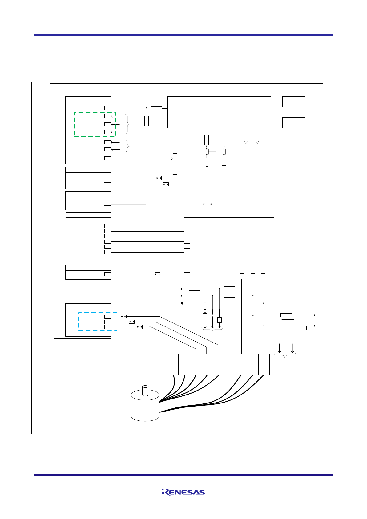
2.1 Hardware configuration
The hardware configuration is shown below.
RL78G1M
A/D converter input
Bus voltage
Rotational speed command
RTO output
Over current detection
Hall sensor input
V
dc
GND
Power supply circuit(5V/12V)
DC24V input
U port
W port
V port
HU port
HW port
HV port
GND port
V
cc
port
VR1
SW1
SW2
Switch input
LED output
LED1 LED2
過電流検出 入力
U
p
V
p
W
p
V
n
U
n
W
n
Inverter circuit
OC
P15 / ANI6
P16 / ANI7
P40
P10 / RTIO00
P11 / RTIO01
P12 / RTIO02
P13 / RTIO03
P14 / RTIO04
P15 / RTIO05
P137 / INTP0
P12
P13
P14
PMSM
P13 / ANI4
P12 / ANI3
P14 / ANI5
Hall control mode
V
u
V
v
V
w
W V U
V
w
V
u
V
v
Sensorless control mode
P125
P137
JP4
JP5
JP5
JP3
JP2
JP1
JP3
JP1
JP2
OPamp IC
P11 / ANI2
P10 / ANI1
I
u
I
v
I
u
I
v
A/D converter
A/D converter
(not used in this system)
LED1 and P40 are disconnected at the time of purchase.
Figure 2-1 – Hardware Configuration Diagram
Page 5

RL78/G1M 120-degree conducting control of permanent magnetic synchronous motor (Implementation)
R01AN5516EJ0100 Rev.1.00 Page 5 of 48
2020.08.01
2.2 Hardware specifications
2.2.1 User interface
Table 2-1 is a list of user interfaces of this system.
Table 2-1 – User Interface
Item
Interface component
Function
VR1
Variable resistor
Rotational speed command value
input (analog values)
SW1
Toggle switch
Command of recovery from error
status
SW2
Toggle switch
(Not used in this system)
LED1
Yellow green LED
(Not used in this system)
LED2
Yellow green LED
(Not used in this system)
LED3
Yellow green LED
(Not used in this system)
RESET
Push switches
(Not used in this system)
The system's RL78/G1M microcontroller port interfaces are listed in Table 2-2.
Table 2-2 – Port Interface
R5F11W68ASM Port Names
Function
P15 / ANI6
Inverter bus voltage measurement
P16 / ANI7
Rotational speed command values input (analog values)
P125
ERROR RESET toggle switch 3
P137
Toggle switch (not used in this system) 4
P40
LED1 on/off control (not used in this system)
P12 / ANI3
U phase voltage measurement (A/D) 2
P13 / ANI4
V phase voltage measurement (A/D) 2
P14 / ANI5
W phase voltage measurement (A/D) 2
P12
Hall effect sensor input
1,2
(HU)
P13
Hall effect sensor input
1,2
(HV)
P14
Hall effect sensor input
1,2
(HW)
P00 / RTIO00
PORT output / PWM output (Up)
P01 / RTIO01
PORT output / PWM output (Vp)
P02 / RTIO02
PORT output / PWM output (Wp)
P03 / RTIO03
PORT output / PWM output (Un)
P04 / RTIO04
PORT output / PWM output (Vn)
P05 / RTIO05
PORT output / PWM output (Wn)
P125 / RESET
System reset (not used in this system)
3
P137 / INTP0
PWM emergency stop input at the time of overcurrent detection
4
1
: When Hall effect sensors on the motor included in the 24V inverter kit are used, equip the ferrite core included in this
kit with cables for 3 Hall effect sensors to avoid sensor noise.
2
: Short 2-3 of JP1-3 in Hall effect sensor control mode, or 1-2 in senseless control mode.
3
: In this system, because P125 is used to detect the status of SW1, short 2-3 of JP4. (However, when writing a program
to the microcontroller, by using the E1emulator, short 1-2.)
4
: In this system, P137 is used for overcurrent detection, so short 1-2 of JP5.
Page 6

RL78/G1M 120-degree conducting control of permanent magnetic synchronous motor (Implementation)
R01AN5516EJ0100 Rev.1.00 Page 6 of 48
2020.08.01
2.2.2 Peripheral functions
Table 2-3 is a list of peripheral functions used in this system.
Table 2-3 – List of Peripheral Functions
Peripheral Function
Usage
10-bit A/D converter
Rotational speed command value input (Board UI
mode)
Inverter bus voltage measurement
Voltage of each phase U, V, and W measurement
Timer Array Unit (TAU)
PWM output
Free-running timer for rotational speed measurement
Delay timer for changing conducting pattern
(sensorless control mode)
12-bit Interval timer (IT)
1 [ms] interval timer
Real-time output control circuit
Output waveform and output port control
External interrupt (INTP0)
Overcurrent detection
(1) 10-bit A/D converter
The rotational speed command value input, U phase voltage (Vu), V phase voltage (Vv), W phase
voltage (Vw), and inverter bus voltage (Vdc) are measured by using the “10-bit A/D converter”.
(2) Timer Array Unit (TAU)
a. PWM output
Used to output non-complementary PWM.
b. Free-running timer for rotational speed measurement
This channel 1 of TAU is used as a free-running counter for rotational speed calculation.
c. Delay timer for changing conducting pattern
The channel 3 of TAU is used as delay timer for changing conducting pattern with π/6 phase from
the zero-crossing point.
(3) 12-bit Interval timer (IT)
Used as a 1 millisecond interval timer.
(4) Real-time output control circuit (RTO)
Sets the Up to Wn PWM, high level and low output.
In addition, by using the forced cutoff function, all output terminals are set to low level output when
overcurrent is detected.
(5) External interrupt (INTP0)
An overcurrent is detected by an external circuit.
Page 7

RL78/G1M 120-degree conducting control of permanent magnetic synchronous motor (Implementation)
R01AN5516EJ0100 Rev.1.00 Page 7 of 48
2020.08.01
2.3 Software structure
2.3.1 Software file structure
The folder and file configurations of the sample programs Table 2-4 are given below.
Table 2-4 – Folder and File Configuration of the Sample Program
Folder
file
content
config
r_mtr_config.h
Common definition for software configuration
r_mtr_motor_parameter.h
Configuration definition for motor parameters
r_mtr_control_parameter.h
Configuration definition for control parameters
r_mtr_inverter_parameter.h
Configuration definition for inverter parameters
application
main
main.h
main.c
Main function
board
r_mtr_board.h
r_mtr_board.c
Function definition for board UI
ics
r_mtr_ics.h
r_mtr_ics.c
Function definition for Analyzer
(Note1)
UI
ICS_define.h
CPU definition for RMW
RL78G1M_vector.c
Interrupt vector function definition for RMW
Ics2_RL78G1M.h
Function declaration for RMW
ICS2_RL78G1M.lib
Communication library for RMW
driver
auto_generation
cstart.asm
hdwinit.asm
iodefine.h
Auto generation files
mtr_ctrl_mrssk.h,
mtr_ctrl_mrssk.c
Function definition for inverter board control
r_mtr_ctrl_rl78g1m.h,
r_mtr_ctrl_rl78g1m.c
Function definition for MCU control
middle
r_mtr_fixed.h
Fixed point definition
r_mtr_common.h
Common definition
r_mtr_parameter.h
Various parameter definition
r_mtr_driver_access.h,
r_mtr_driver_access.c
Function definition for User access
r_mtr_statemachine.h,
r_mtr_statemachine.c
Function definition for state transition
r_mtr_120.h
r_mtr_120.c
Function definition for 120-degree conducting control
r_mtr_interrupt.c
Interrupt function definition
Note 1: Regarding the specification of the Analyzer function in the motor control development support tool “Renesas Motor Workbench
(RMW)”, please refer to Chapter 4.
The identifier ‘ics/ICS (ICS is the previous motor control development support tool, ‘In Circuit Scope’) is attached to the name of
folders, files, functions, and variables related to ‘Renesas Motor Workbench’.
Page 8
RL78/G1M 120-degree conducting control of permanent magnetic synchronous motor (Implementation)
R01AN5516EJ0100 Rev.1.00 Page 8 of 48
2020.08.01
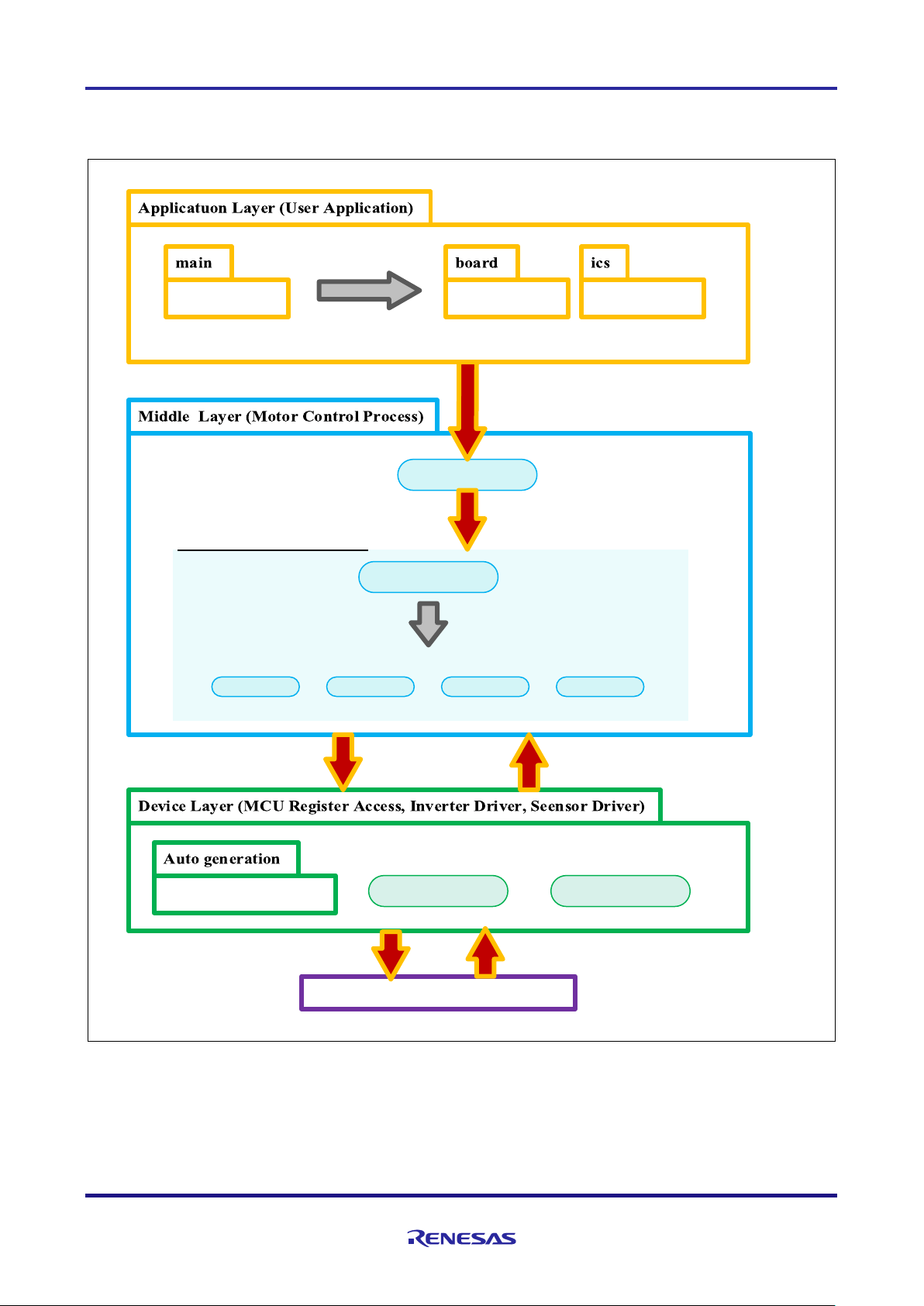
2.3.2 Module configuration
Figure 2-2 shows module configuration of the sample programs.
Function Call
driver_access
Set Control Parameter & Command
Motor Control Process Modules
interrupt
Function Call
Other Control Modules
MCU Inverter
Set PWM duty
Voltage, Sensor signals
H/W Layer (MCU, Inverter)
Output PWM Signal A/D Convertor, PORT
Figure 2-2 – Module Configuration of the Sample Programs
Page 9

RL78/G1M 120-degree conducting control of permanent magnetic synchronous motor (Implementation)
R01AN5516EJ0100 Rev.1.00 Page 9 of 48
2020.08.01
2.4 Software specifications
Table 2-5 shows the basic specifications of target software of this application note. For details on 120degree conducting control, refer to the application note “120-degree conducting control of permanent magnet
synchronous motor: algorithm”.
Table 2-5 – Basic Specifications of Software
Item
Content
Control method
120-degree conducting method (chopping upper arm)
Motor rotation start/stop
Determined based on the input value of VR1 (P16) (minimum speed or
more: rotation starts, less than minimum speed: stop)
or input from Renesas Motor Workbench
Position detection of rotor
magnetic pole
Hall effect sensor: Position detection based on signal from Hall effect
sensors (every 60 degrees)
Sensorless: Position detection based on induced voltage measured by A/D
converters (every 60 degrees)
・When position of rotor is detected, PWM duty and conducting pattern are
set.
Input voltage
DC24[V]
Main clock frequency
CPU clock: f
CLK
20 [MHz]
Carrier frequency (PWM)
20 [kHz]
Control cycle
Speed PI control: every 1 [ms]
Rotational speed control
range
Hall effect sensor control mode: 530 [rpm] to 3200 [rpm]
(Note1)
Sensorless control mode: 265 [rpm] to 3200 [rpm]
(Note1)
Both CW and CCW are supported
Optimization
Perform the default optimization (None)
Processing stop for
protection
・Disables the motor control signal output (six outputs), under any of the
following conditions.
1. Inverter bus voltage exceeds 28 V (monitored per 1 [ms])
2. Inverter bus voltage is less than 15 V (monitored per 1 [ms])
3. Rotational speed exceeds 3900 rpm (monitored per 1 [ms])
4. Hall pattern change or zero-crossing are not detected for 200 [ms].
5. Detection of unexpected output voltage pattern
6. Detection of overcurrent by external circuit (low level input in INTP0
port)
Note1 : Please refrain from driving motor over rated speed for a long period.
2.5 User option bytes
The settings of the user option byte area of the RL78/G1M flash memory are shown below.
Table 2-6 – User option byte settings
Setting
Address
value
Description
F2E3F9
000C0H
11110010B
Enable watchdog timer counter operation
(Starts counting after reset is released)
Overflow time: 7.36 [ms]
000C1H
11100011B
・P125/KR1/RESET pin: Port function
・Selectable power-on reset detection voltage
Rising edge: 4.28 [V]
Falling edge: 4.20 [V]
000C2H
11111001B
CPU clock fCLK: 20 [MHz]
Page 10

RL78/G1M 120-degree conducting control of permanent magnetic synchronous motor (Implementation)
R01AN5516EJ0100 Rev.1.00 Page 10 of 48
2020.08.01
3. Descriptions of the control program
The target sample programs of this application note are explained here.
3.1 Contents of control
3.1.1 Motor start/stop
Starting and stopping of the motor are controlled by input from Renesas Motor Workbench or VR1. In
addition, an analog input port is assigned to VR1. The input is A/D converted within the main loop to generate a
rotational speed command value. When the rotation command value exceeds the minimum speed (Hall
control mode: 530 [rpm], sensorless control mode: 265 [rpm]), the rotation starts, and when it is less than the
minimum speed, the rotation stops.
3.1.2 A/D Converter
(1) Motor rotational speed command value
The motor rotational speed command value can be set by Renesas Motor Workbench input or A/D
conversion of the VR1 output value (analog value). The A/D converted VR1 value is used as rotational speed
command value, as shown below. Maximum value of conversion ratio is set to achieve maximum speed by
VR1 input. Only higher 8bits are used for calculation of rotational speed command value.
Table 3-1 – Conversion Ratio of the Rotation Speed Command Value
Item
Conversion ratio
(Command value: A/D conversion value)
Channel
Rotational speed
command value
CW
0 [rpm] to 3200 [rpm] : 01FFH to 03FFH
ANI7
CCW
-3200 [rpm] to 0 [rpm] : 0000H to 01FFH
(2) Inverter bus voltage
Inverter bus voltage is measured as given in Table 3-2. It is used for modulation factor calculation and
over/low voltage detection. (When an abnormality is detected, PWM is stopped). Only higher 8bits are used
for calculation of bus voltage.
Table 3-2 – Inverter Bus Voltage Conversion Ratio
Item
Conversion ratio
(Inverter bus voltage: A/D conversion value)
Channel
Inverter bus voltage
0 [V] to 111 [V] : 0000H to 03FFH
ANI6
(3) U phase, V phase, and W phase voltage
The U, V and W phase voltages are measured as shown in Table 3-3 and are used for determining zerocrossing of induced voltage.
Table 3-3 – Conversion Ratio of U, V, and W Phase Voltage
Item
Conversion ratio
(U, V, and W phase voltage: A/D conversion value)
Channel
U, V, W phase
voltages
0 [V] to 111 [V] : 0000H to 03FFH
ANI12, ANI13,
ANI14
Note: For more details on A/D conversion, refer to RL78/G1M User’s Manual: Hardware.
Page 11
RL78/G1M 120-degree conducting control of permanent magnetic synchronous motor (Implementation)
R01AN5516EJ0100 Rev.1.00 Page 11 of 48
2020.08.01
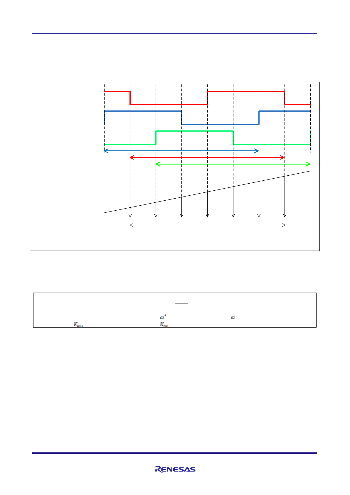
3.1.3 Speed control
In this system, rotational speed is calculated from the difference between the current timer value and the
previous timer value 2π [rad]. The timer values are obtained when patterns are switched after Hall effect
sensor pattern change at Hall effect sensor control mode or zero-crossing of induced voltage at sensorless
control mode, while having the timer of performed free running.
U phase pattern
2p
Timer counter
Check Check Check Check Check Check Check
Counter value difference
Motor rotational speed [rad/s] = (2π × frequency of timer) / (difference of timer counts)
V phase pattern
W phase pattern
2p
2p
Figure 3-1 – Method of Calculation for Rotational Speed
The target sample software of this application note uses PI control for speed control. A voltage command
value is calculated by the following formula of speed PI control.
))((
*
−+=
s
K
Kv
I
P
𝑣
∗
: Voltage command value : Speed command value : Rotation speed
: Speed PI proportional gain : Speed PI integral gain 𝑠: Laplace operator
For more details on PI control, please refer to specialized books.
Page 12
RL78/G1M 120-degree conducting control of permanent magnetic synchronous motor (Implementation)
R01AN5516EJ0100 Rev.1.00 Page 12 of 48
2020.08.01
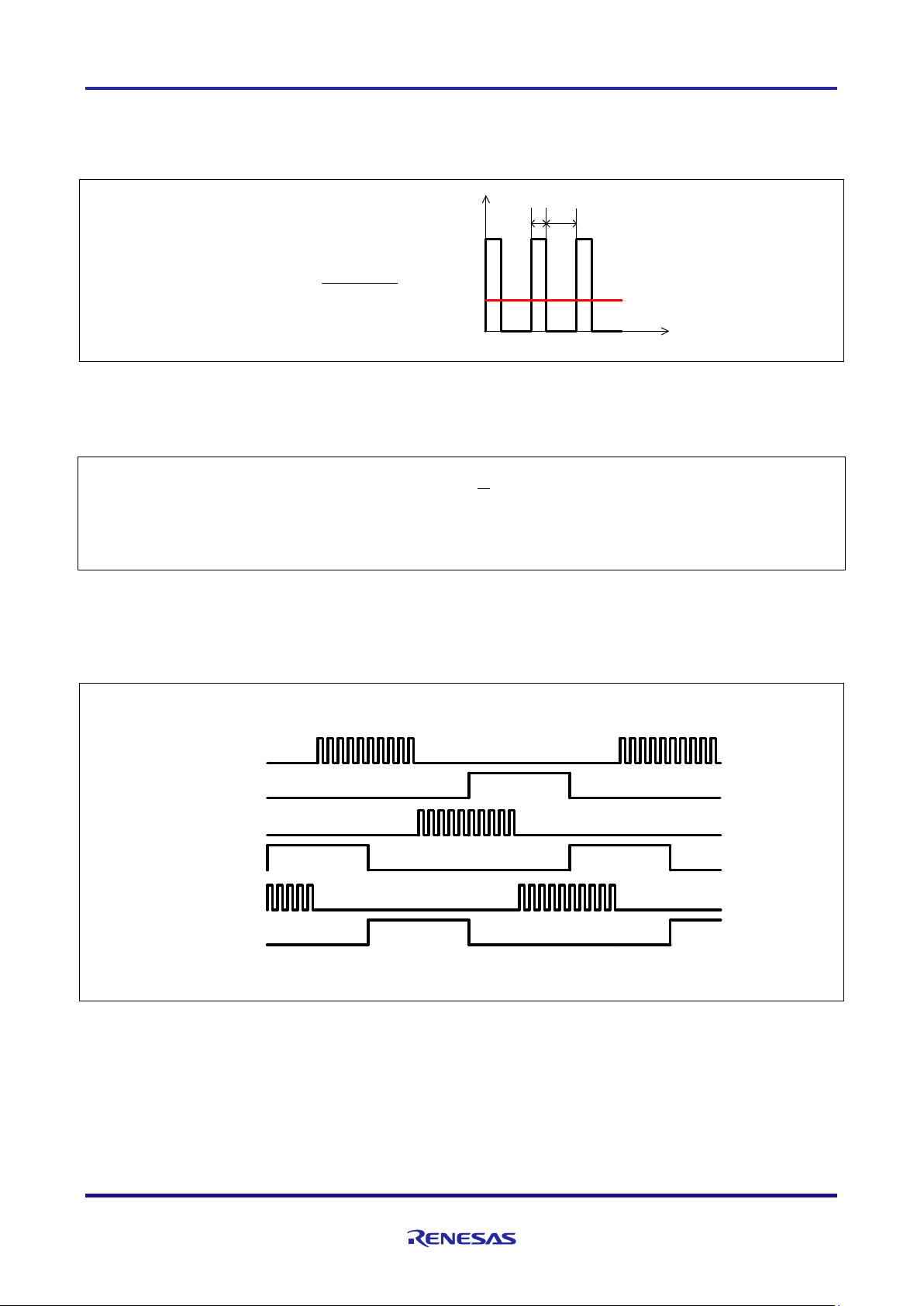
3.1.4 Voltage control by PWM
PWM control is used for controlling output voltage. The PWM control is a control method that continuously
adjusts the average voltage by varying the duty of pulse, as shown in Figure 3-2.
Average
voltage
t
V
T
ON
T
OFF
T
ON
+ T
OFF
T
ON
Duty = × 100 [%]
Figure 3-2 – PWM Control
Here, modulation factor “m” is defined as follows.
𝑚 =
𝑉
𝐸
This modulation factor is set to resisters for PWM duty in TAU.
In the target software of this application note, non-complementary upper arm chopping is used to control
the output voltage and speed. Figure 3-3 shows an example of output waveforms when upper arm chopping
is used.
UP
UN
VP
VN
WP
WN
Figure 3-3 – Non-Complementary Upper Arm Chopping
𝑚: Modulation factor 𝑉: Command value voltage 𝐸: Inverter bus voltage
Page 13
RL78/G1M 120-degree conducting control of permanent magnetic synchronous motor (Implementation)
R01AN5516EJ0100 Rev.1.00 Page 13 of 48
2020.08.01
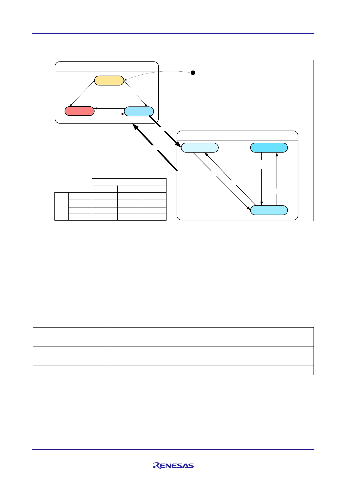
3.1.5 State transitions
Figure 3-4 shows state transition diagrams of 120-degree conducting control software.
SYSTEM MODE (User System)
INACTIVE
ERROR
POWER ON/
HARDWAE RESET
[INIT ERROR]
RUN MODE (Motor Control)
INIT
STOP
DRIVE
ACTIVE
[ERROR]
[RESET]
STOP
DRIVE
ERROR
RESET
RUN MODE
INIT DRIVE STOP
STOP
INIT INIT
INIT
STOP STOP
DRIVE
STOP
DRIVE
STOP
DRIVE
STOP
EVENT
[HW INIT END]
[RESET EVENT]
[DRIVE EVENT]
[ERROR EVENT]
[STOP EVENT]
[STOP EVENT]
[INIT EVENT]
[ERROR STATUS]
Figure 3-4 – State Transition Diagram 120-degree Conducting Control Software
(1) SYSTEM MODE
“SYSTEM MODE” indicates the operating states of the system. “SYSTEM MODE” has 3 states, which are
motor drive stop (INACTIVE), motor drive (ACTIVE), and abnormal condition (ERROR).
(2) RUN MODE
“RUN MODE” indicates the condition of the motor control. The state is changed by occurrence of “EVENT”.
(3) EVENT
“Event” indicates the change of “RUN MODE”. When “EVENT” occurs, “RUN MODE” changes as shown
table in Figure 3-4. Each “Event” is caused by occurrence as shown in Table 3-4.
Table 3-4 – List of “EVENT”
“EVENT” name
Occurrence factor
STOP
By user operation
DRIVE
By user operation
ERROR
When the system detects an error
RESET
By user operation
Page 14
RL78/G1M 120-degree conducting control of permanent magnetic synchronous motor (Implementation)
R01AN5516EJ0100 Rev.1.00 Page 14 of 48
2020.08.01
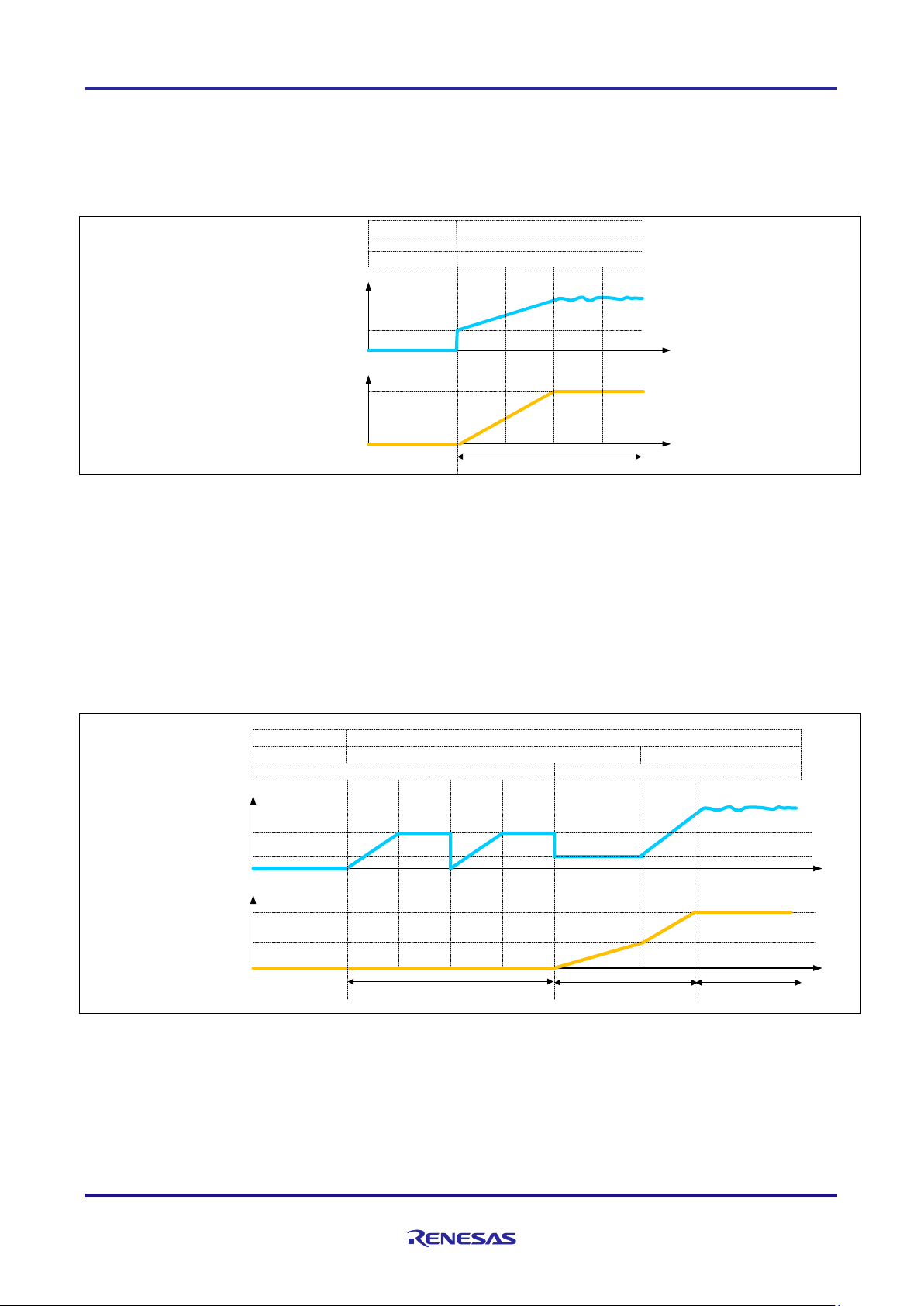
3.1.6 Start-up method
(1) Hall effect sensor control mode
In the Hall effect sensor control mode, after changing to “MTR_MODE_DRIVE”, the output pattern is
selected from the initial Hall effect sensor signal. Then, voltage is applied and the state is changed to PI
control mode. The rotational speed is calculated after the second hall effect sensor interruption.
Voltage
[V]
RUN MODE
0
0
Reference voltage status
Reference speed status
MTR_SPEED_MANUAl
(1)
Speed
[rad/s]
g_st_120.st_hall_
s2_start_ref_v
g_st_120.s2_ref_speed_rad_ctrl
Speed PI control
MTR_V_PI_OUTPUT
(2)
MTR_V_ZERO_CONST
(0)
MTR_SPEED_ZERO_CONST
(0)
MTR_MODE_DRIVEMTR_MODE_STOP
Figure 3-5 – Start-up sequence (hall effect sensor control mode)
(2) Sensorless control mode
In sensorless control mode, the position of the magnetic poles is estimated every 60 degrees from induced
voltage that is generated from the variation of magnetic flux due to the rotation of the permanent magnet
(rotor). However, since the induced voltage is generated by the rotation, at low speed it is difficult to estimate
the position of the rotor.
Therefore, the method to generate a rotating magnetic field by forcibly switching conducting pattern in the
synchronous speed regardless of the position of the rotor, is often used.
Figure 3-6 shows the start-up method in the sample software. In “MTR_MODE_DRIVE”, at first, the rotor is
drawn in. Second, mode is changed to open-loop drive mode. When reference control speed reaches to
change speed, mode is changed to PI control mode.
Voltage
[V]
RUN MODE
0
0
Reference voltage status
Reference speed status
MTR_SPEED_MANUAl
(1)
Speed
[rad/s]
MTR_V_PI_OUTPUT
(2)
g_st_120.st_less.
s2_ol_ref_v
g_st_120.st_less.
s2_ol2less_speed_rad
g_st_120.s2_ref_speed_rad
Open-loop Speed PI control
g_st_120.st_less.
s2_draw_in_ref_v
MTR_V_MANUAL
(1)
MTR_V_ZERO_CONST
(0)
MTR_SPEED_ZERO_CONST
(0)
MTR_MODE_DRIVEMTR_MODE_STOP
Draw-in
Figure 3-6 – Startup Sequence (Sensorless Control Mode)
Page 15

RL78/G1M 120-degree conducting control of permanent magnetic synchronous motor (Implementation)
R01AN5516EJ0100 Rev.1.00 Page 15 of 48
2020.08.01
3.1.7 System protection function
This system has the following types of error status and emergency stop functions in case of occurrence of
respective error. Refer to Table 3-5 for settings related to the system protection function.
・Overcurrent error for hardware
When an emergency stop signal (over current detection) from the external hardware is detected, voltage
output is stopped.
・Overvoltage error
The inverter bus voltage is monitored at the overvoltage monitoring cycle. When the inverter bus voltage
exceeds the overvoltage limit, voltage output is stopped. The threshold value of the overvoltage is set in
consideration of the error of resistance value of the detection circuit.
・Low voltage error
The inverter bus voltage is monitored at the low voltage monitoring cycle. When the inverter bus voltage
lowers undervoltage limit, voltage output is stopped. The threshold value of the low voltage is set in
consideration of the error of resistance value of the detection circuit.
・Rotational speed error
The rotational speed is monitored at the rotational speed monitoring cycle. When the rotational speed
exceeds the over speed limit, voltage output is stopped.
・Timeout error
The timeout counter is monitored at the timeout monitoring cycle. When pattern switching by Hall pattern
change in Hall effect sensor control mode or zero-crossing of induced voltage in sensorless control mode
don’t happen for a timeout period, voltage output is stopped.
・Pattern error
The output voltage pattern is monitored at the pattern monitoring cycle. When unexpected pattern is
detected in voltage pattern set from Hall effect sensor in Hall effect sensor control mode or induced
voltage in sensorless control mode, voltage output is stopped.
Table 3-5 – Setting Value of Each System Protection Function
Kinds of error
Threshold
Over current error
Over current limit [A]
2.0
Over voltage error
Overvoltage limit [V]
28
Monitoring cycle [ms]
1
Under voltage error
Low voltage limit [V]
15
Monitoring cycle [ms]
1
Rotational speed error
Speed limit [rpm]
3900
Monitoring cycle [ms]
1
Timeout error
Timeout value [ms]
200
Monitoring cycle [ms]
1
Page 16

RL78/G1M 120-degree conducting control of permanent magnetic synchronous motor (Implementation)
R01AN5516EJ0100 Rev.1.00 Page 16 of 48
2020.08.01
3.2 Function specifications of 120-degree conducting control software
Lists of functions used in this control program are shown below. Functions not used in this system are
undescribed.
Table 3-6 – List of Functions “main.c”
file
function
process
main.c
main
argument: none
return: none
Initialization and main loop
・initialization
⇒initialization of hardware
⇒initialization of system variables
⇒initialization of ICS communication
⇒initialization of control system
⇒reset process
⇒waiting for stability of bus voltage
・main loop
⇒system control depending on input from UI
⇒clear watch dog timer
⇒ICS communication process
ics_ui
argument: none
return: none
Process for ICS UI (GUI)
・input values of command variables to ICS variables
・change motor status depending on input event
・initialization of system variables when reset event occurs
board_ui
argument: none
return: none
Process of board UI (H/W)
・change motor status depending on state of switch
・determination of command rotational speed by value of
VR1
software_init
argument: none
return: none
Initialization of system variables
・initialization of variables for main process
・initialization of ICS variables
mtr_ics_process [inline function]
argument: none
return: none
ICS communication process
Page 17

RL78/G1M 120-degree conducting control of permanent magnetic synchronous motor (Implementation)
R01AN5516EJ0100 Rev.1.00 Page 17 of 48
2020.08.01
Table 3-7 – List of Functions “r_mtr_ics.c”
file
function
process
r_mtr_ics.c
mtr_set_com_variables
argument: none
return: none
Preprocess to set control variables
・input values of command variables to ICS variables
・input values of ICS variables to ICS buffer variables
mtr_ics_variables_init
argument: none
return: none
Initialization of command variables
R_MTR_Limit
argument: (int16_t) s2_value / target value
(int16_t) s2_max / maximum limit
(int16_t) s2_min / minimum limit
return: (int16_t) s2_temp / limited value
Limit between maximum and minimum values
Table 3-8 – List of Functions “r_mtr_board.c”
file
function
process
r_mtr_board.c
mtr_remove_chattering
argument: (uint8_t) u1_sw / switch signal
(uint8_t) u1_on_off / switch status
return: (uint8_t) u1_flag_chattering / flag for chattering
Remove chattering of switch signal
Page 18

RL78/G1M 120-degree conducting control of permanent magnetic synchronous motor (Implementation)
R01AN5516EJ0100 Rev.1.00 Page 18 of 48
2020.08.01
Table 3-9 – List of Functions “r_mtr_ctrl_mrssk.c”
file
function
process
r_mtr_ctrl_mrssk.c
R_MTR_GetSw1
argument: none
return: (uint8_t) MTR_PORT_SW1 / state of SW1
Get state of SW1
Table 3-10 – List of Functions in “r_mtr_ctrl_rl78g1m.h”
file
function
process
r_mtr_ctrl_rl78g1m.h
mtr_input_hall(signal)
argument: none
return: none
Input Hall effect sensor signal
mtr_get_tcr02(cnt)
argument: none
return: none
Get free run timer counts
mtr_set_rtooutc(gate)
argument: none
return: none
Set voltage pattern by RTO
mtr_set_tdr01(duty)
argument: none
return: none
Set PWM duty
mtr_clear_wdt()
argument: none
return: none
Clear watch dog timer (WDT)
mtr_get_adcr(v)
argument: none
return: none
Get A/D result
mtr_clear_rtointpclr()
argument: none
return: none
Clear forced cutoff
mtr_oc_intr_enable()
argument: none
return: none
Enable overcurrent interrupt
mtr_oc_intr_disable()
argument: none
return: none
Disable overcurrent interrupt
mtr_set_tdr03()
argument: none
return: none
[sensorless control mode]
Set delay count
mtr_start_delay_cnt()
argument: none
return: none
[sensorless control mode]
Start delay timer
mtr_stop_delay_cnt()
argument: none
return: none
[sensorless control mode]
Stop delay timer
mtr_clear_inttm03()
argument: none
return: none
[sensorless control mode]
Disable delay interrupt
Page 19

RL78/G1M 120-degree conducting control of permanent magnetic synchronous motor (Implementation)
R01AN5516EJ0100 Rev.1.00 Page 19 of 48
2020.08.01
Table 3-11 – List of Functions in “r_mtr_ctrl_rl78g1m.c”
file
function
process
r_mtr_ctrl_rl78g1m.c
R_MTR_InitHardware
argument: none
return: none
Initialization of peripheral functions
mtr_init_unused_pins
argument: none
return: none
Initialization of unused pins
mtr_init_ui
argument: none
return: none
Initialization of ports for board UI
mtr_init_clock
argument: none
return: none
Initialization of clock
mtr_init_it
argument: none
return: none
Initialization of 12-bit interval timer (IT)
mtr_init_rto
argument: none
return: none
Initialization of real-time output control circuit
(RTO)
mtr_init_adc
argument: none
return: none
Initialization of A/D converter
mtr_init_tau
argument: none
return: none
Initialization of timer array unit (TAU)
mtr_init_intp
argument: none
return: none
Initialization of external interrupt (INTP)
mtr_init_hall
argument: none
return: none
[Hall effect sensor control mode]
Initialization of pins for hall effect sensor
R_MTR_get_adc
argument: (uint8_t) u1_ad_ch / channel of A/D
conversion
return: (int16_t) s2_ad_value / result of A/D conversion
Get the result of A/D conversion
R_MTR_get_v_uvw_adc
argument: (int16_t) *s2_v_uvw / UVW voltages
return: none
[sensorless control mode]
Get the results of A/D conversion of UVW
voltage
R_MTR_ctrl_stop
argument: none
return: none
Stop motor control
・Voltage output prohibited
Page 20

RL78/G1M 120-degree conducting control of permanent magnetic synchronous motor (Implementation)
R01AN5516EJ0100 Rev.1.00 Page 20 of 48
2020.08.01
Table 3-12 – List of Functions “r_mtr_driver_access.c”
file
function
process
r_mtr_driver_access.c
R_MTR_InitControl
argument: none
return: none
Initialization of control system
・initialization of motor status
・initialization of control variables
R_MTR_IcsInput
argument: (mtr_ctrl_input_t) *st_ics_input / ICS structure
return: none
Input values of ICS variables to ICS
buffer variables
R_MTR_SetVariables [inline function]
argument: none
return: none
Input values of ICS buffer variables to
control variables
R_MTR_InputBuffParamReset
argument: none
return: none
Reset ICS buffer variables
R_MTR_ExecEvent
argument: (uint8_t) u1_event / event
return: none
Change motor status and execute
event process
R_MTR_GetStatus
argument: none
return: (uint8_t) mtr_statemachine_get_status(g_st_120.st_stm)
/ motor status
Get motor status
R_MTR_GetErrorStatus
argument: none
return: (uint16_t) g_st_120.u2_error_status
/ error status
Get error status
R_MTR_Get_Dir
argument: none
return: (uint8_t) g_st_120.u1_dir / direction of rotation
Get direction of rotation
R_MTR_SetSpeed
argument: (int16_t) s2_ref_speed_rpm / command rotational speed
return: (uint8_t) u1_stop_req / flag for requiring flag
Set command speed
R_MTR_ChargeCapacitor
argument: none
return: (uint16_t) u2_charge_cap_error / timeout error
Waiting for stability of bus voltage
R_MTR_UpdatePolling
argument: none
return: none
Set control variables
Page 21

RL78/G1M 120-degree conducting control of permanent magnetic synchronous motor (Implementation)
R01AN5516EJ0100 Rev.1.00 Page 21 of 48
2020.08.01
Table 3-13 – List of Functions “r_mtr_statemachine.c”
file
function
process
r_mtr_statemachine.c
mtr_statemachine_init
argument: (st_mtr_statemachine_t) *p_state_machine / structure for motor status
return: none
Initialization of motor
status
mtr_statemacine_reset
argument: (st_mtr_statemachine_t) *p_state_machine / structure for motor status
return: none
Reset motor status
motor status
mtr_state_machine_event
argument: (st_mtr_statemachine_t) *p_state_machine / structure for motor status
(void) *p_object / structure for control variables
(uint8_t) u1_event / event
return: none
Execute event process
mtr_statemachine_get_status
argument: (st_mtr_statemachine_t) *p_state_machine / structure for motor status
return: (uint8_t) p_state_machine->u1_status / motor status
Get motor status
mtr_act_none
argument: (st_mtr_statemachine_t) *st_stm / structure for motor status
(void) *p_param / structure for control variables
return: none
No process is performed
mtr_act_init
argument: (st_mtr_statemachine_t) *st_stm / structure for motor status
(void) *p_param / structure for control variables
return: none
Initialization of
control variables
mtr_act_error
argument: (st_mtr_statemachine_t) *st_stm / structure for motor status
(void) *p_param / structure for control variables
return: none
Stop motor control
mtr_act_drive
argument: (st_mtr_statemachine_t) *st_stm / structure for motor status
(void) *p_param / structure for control variables
return: none
Reset control variables
mtr_act_stop
argument: (st_mtr_statemachine_t) *st_stm / structure for motor status
(void) *p_param / structure for control variables
return: none
Stop motor control
Page 22

RL78/G1M 120-degree conducting control of permanent magnetic synchronous motor (Implementation)
R01AN5516EJ0100 Rev.1.00 Page 22 of 48
2020.08.01
Table 3-14 – List of Functions in “r_mtr_120.h”
file
function
process
r_mtr_120.h
mtr_conv_q_voltage(v)
argument: none
return: none
Q value conversion of voltage
mtr_conv_kp_voltage(kp)
argument: none
return: none
Q value conversion of proportional
gain
mtr_conv_kidt_voltage(kidt)
argument: none
return: none
Q value conversion of integral gain
mtr_conv_rpm2rad(v)
argument: none
return: none
Unit converson of rotational speed
from [rpm] to [rad/s]
Table 3-15 – List of Functions in “r_mtr_120.c”
file
function
process
r_mtr_120.c
mtr_120_motor_default_init
argument: (st_mtr_120_control_t) *st_120 / structure for control variables
return: none
Initialization of control
variables
mtr_120_motor_reset
argument: (st_mtr_120_control_t) *st_120 / structure for control variables
return: none
Reset control variables
Page 23

RL78/G1M 120-degree conducting control of permanent magnetic synchronous motor (Implementation)
R01AN5516EJ0100 Rev.1.00 Page 23 of 48
2020.08.01
Table 3-16 – List of Functions “r_mtr_interrupt.c” [1/ 3]
file
function
process
r_mtr_interrupt.c
mtr_over_current_interrupt
argument: none
return: none
Overcurrent detection process
・disable over current interrutp
・execute error event
・set error status
mtr_carrier_interrupt
argument: none
return: none
Carrier interrupt
【Hall effect sensor control mode】
・obtain bus voltage
・detect Hall pattern change
・prepare for rotational speed calculation
・set voltage pattern
[sensorless control mode]
・obtain UVW and bus voltages
・draw-in process
・zero-cross detection
・prepare for rotational speed calculation
・open-loop process
・calculate delay counts
・start delay timer
mtr_prepare_speed_calc [inline function]
argument: none
return: none
Prepare for Calculation of rotational speed
mtr_set_chopping_pattern [inline function]
argument: (uint8_t) u1_pattern / conducting pattern
return: none
Set chopping pattern
mtr_set_speed_ref [inline function]
argument: none
return: none
Set reference speed
mtr_set_voltage_ref [inline function]
argument: none
return: none
Set reference voltage
mtr_pi_ctrl [inline function]
argument: (st_mtr_pi_control_t) *pi_ctrl / structure for PI control
return: (int16_t) s2_ref_v_delta / variation of output voltage
PI control calculation (velocity form)
mtr_duty_calc [inline function]
argument: (int16_t) s2_ref_v / reference voltage
(int16_t) s2_vdc_ad / bus voltage
return: (uint16_t) u4_temp / duty
Duty calculation
mtr_abs [inline function]
argument: (int16_t) s2_value / input value
return: (int16_t) s2_temp / conversion value
Conversion to absolute value
mtr_limit_value [inline function]
argument: (int16_t) s2_value / input value
(int16_t) s2_limit_value / limit value
return: (int16_t) s2_temp / conversion value
Limit process
Page 24

RL78/G1M 120-degree conducting control of permanent magnetic synchronous motor (Implementation)
R01AN5516EJ0100 Rev.1.00 Page 24 of 48
2020.08.01
Table 3-17 – List of Functions “r_mtr_interrupt.c” [2/3]
file
function
process
r_mtr_interrupt.c
mtr_error_check [inline function]
argument: none
return: none
Error check
mtr_1ms_interrupt_hall
argument: none
return: none
[Hall effect sensor control mode]
IT interrupt (1 [ms))
・set reference speed and voltage states
・calculate reference speed and voltage
・starting-up process
・calculate rotational speed
・check error
mtr_speed_calc [inline function]
argument: none
return: none
[Hall effect sensor control mode]
Calculate rotational speed
mtr_1ms_interrupt_less
argument: none
return: none
[sensorless control mode]
IT interrupt (1 [ms])
・set reference speed and voltage states
・calculate reference speed and voltage
・draw-in process
・calculate rotational speed
・calculate counts for open-loop drive
・check error
mtr_delay_interrupt
argument: none
return: none
[sensorless control mode]
TAU03 interrupt
・set voltage pattern
mtr_draw_in_pattern_set [inline function]
argument: none
return: none
[sensorless control mode]
Set voltage pattern in draw-in state
mtr_detect_zerocross [inline function]
argument: (st_mtr_sensorless_control_t) *st_less
/ structure for control variables
return: (uint16_t) u2_temp_signal / voltage pattern
[sensorless control mode]
Estimate position of rotor from zero-crossing
of induced voltage
mtr_drive_openloop [inline function]
argument: none
return: none
[sensorless control mode]
Open-loop drive process
mtr_set_angle_shift [inline function]
argument: none
return: none
[sensorless control mode]
Calculation of delay count after zero-crossing
Page 25

RL78/G1M 120-degree conducting control of permanent magnetic synchronous motor (Implementation)
R01AN5516EJ0100 Rev.1.00 Page 25 of 48
2020.08.01
Table 3-18 – List of Functions “r_mtr_interrupt.c” [3/3]
file
function
process
r_mtr_interrupt.c
mtr_openloop_pattern_set [inline function]
argument: none
return: (uint8_t) u1_pattern / voltage pattern
[sensorless control mode]
Set voltage pattern at open-loop drive
mtr_start_delay_timer [inline function]
argument: none
return: none
[sensorless control mode]
Start delay timer
mtr_stop_delay_timer [inline function]
argument: none
return: none
[sensorless control mode]
Stop delay timer
Page 26

RL78/G1M 120-degree conducting control of permanent magnetic synchronous motor (Implementation)
R01AN5516EJ0100 Rev.1.00 Page 26 of 48
2020.08.01
3.3 Lists of variables of sensorless 120-degree conducting control software
Lists of variables used in this control program are shown below. However, note that the local variables are
not mentioned.
In the sample programs, fixed-point number is used for calculation. Therefore, in advance, some control
variables are set in fixed-point number. Bits number in fractional part of fixed-point number is expressed in
the Q format. “Qn” means n bits left shift.
Table 3-19 – List of variables “main.c”
variable
type
Qn
content
Remarks
g_u1_system_mode
static uint8_t
Q0
Mode system management
g_u1_motor_status
static uint8_t
Q0
Motor status management
g_u1_reset_req
static uint8_t
Q0
Reset command flag for SW2
g_u1_stop_req
static uint8_t
Q0
Stop command flag for VR1
g_u2_error_status
static uint16_t
Q0
Error status management
g_u1_flag_ui_change
static uint8_t
Q0
UI changing flag
g_u2_conf_hw
uint16_t
Q0
RMW configuration variables
g_u2_conf_sw
uint16_t
Q0
g_u2_conf_tool
uint16_t
Q0
gui_u1_active_gui
uint8_t
Q0
g_u2_conf_sw_ver
uint16_t
Q0
com_s2_sw_userif
int16_t
Q0
Management variable for UI
0:ICS_UI
1:BOARD_UI
g_s2_sw_userif
int16_t
Q0
com_u1_run_event
uint8_t
Q0
Input event and change run mode
0 : MTR_EVENT_STOP
1 : MTR_EVENT_DRIVE
2 : MTR_EVENT_ERROR
3 : MTR_EVENT_RESET
g_u1_run_event
uint8_t
Q0
g_u2_init_error
uint16_t
Q0
Initialization error management
Table 3-20 – List of variables “r_mtr_board.c”
variable
type
Qn
content
Remarks
u1_sw_cnt
static uint8_t
Q0
Counter for judgement of chattering
Page 27

RL78/G1M 120-degree conducting control of permanent magnetic synchronous motor (Implementation)
R01AN5516EJ0100 Rev.1.00 Page 27 of 48
2020.08.01
Table 3-21 – List of variables “r_mtr_ics.c”
variable
type
Qn
content
Remarks
com_u1_direction
uint8_t
Q0
Direction of rotation
0:CW 1:CCW
com_s2_ref_speed_rpm
int16_t
Q0
Command rotational speed [rpm]
Mechanical angle
com_s2_ramp_limit_v
int16_t
Q9
Limit of variation of voltage [V/ms]
com_s2_kp_speed
int16_t
Q18
Proportional gain for speed PI control [V s/rad]
com_s2_kidt_speed
int16_t
Q22
Integral gain for speed PI control
[V s/rad]
com_s2_ramp_speed_rpm
int16_t
Q0
Acceleration [rpm/ms]
Hall effect sensor
control model
com_s2_start_ref_v
int16_t
Q9
Reference voltage at starting [V]
com_s2_ol_ramp_speed_rpm
int16_t
Q0
Acceleration at open-loop drive [rpm/ms]
sensorless control
mode
com_s2_less_ramp_speed_r
pm
int16_t
Q0
Acceleration at sensorless control [rpm/ms]
com_s2_draw_in_ref_v
int16_t
Q9
Reference voltage at draw-in [V]
com_s2_ol_ref_v
int16_t
Q9
Reference voltage at open-loop drive [V]
com_s2_ol2less_speed_rpm
int16_t
Q0
Speed to transition to PI control[rpm]
com_s2_angle_shift_adjust
int16_t
Q0
adjust delay counts
com_s2_enable_write
int16_t
Q0
Variable to allow to input ICS structure
g_s2_enable_write
int16_t
Q0
st_ics_input
mtr_ctrl_input_t
Q0
Variable to allow to input ICS structure
com_u1_direction
uint8_t
Q0
Structure for ICS input
structure
Table 3-22 – List of variables “r_mtr_parameter.h / Structure : st_mtr_ctrl_gain_t”
variable
type
Qn
content
Remarks
s2_speed_pi_kp
int16_t
Q18
Proportional gain for speed PI control
s2_speed_pi_kidt
int16_t
Q22
Integral gain for speed PI control
Page 28

RL78/G1M 120-degree conducting control of permanent magnetic synchronous motor (Implementation)
R01AN5516EJ0100 Rev.1.00 Page 28 of 48
2020.08.01
Table 3-23 – List of variables “r_mtr_driver_access.h / Structure : mtr_ctrl_input_t”
variable
type
Qn
content
Remarks
u1_dir
uint8_t
Q0
Direction of rotation
s2_ref_speed_rad
int16_t
Q4
Command rotational speed [rad/s]
electric angle
s2_ramp_limit_v
int16_t
Q9
Limit of variation of voltage [V/ms]
s2_ramp_ speed_rad
int16_t
Q4
Acceleration [krad/s2]
s2_start_ref_v
int16_t
Q9
Reference voltage at starting [V]
Hall effect sensor
control mode
s2_ol_ramp_speed_rad
int16_t
Q4
Acceleration at open-loop drive [krad/s2]
sensorless
control mode
s2_less_ramp_speed_rad
int16_t
Q4
Acceleration at sensorless control [krad/s2]
s2_draw_in_ref_v
int16_t
Q9
Reference voltage at draw-in [V]
s2_ol_ref_v
int16_t
Q9
Reference voltage at open-loop drive [V]
s2_ol2less_speed_rad
int16_t
Q4
Speed to transition to PI control[rad/s]
s2_angle_shift_adjust
int16_t
Q0
adjust delay counts
st_gain
st_mtr_ctrl_gain_t
-
structure for PI control
structure
Table 3-24 – List of variable “r_mtr_driver_access.c”
variable
type
Qn
content
Remarks
g_u1_trig_enable_write
uint8_t
Q0
Flag to allow to input ICS values
st_ics_input_buff
mtr_ctrl_input_t
-
Buffer for ICS input
structure
Table 3-25 – List of variables “r_mtr_statemachine.h / Structure : st_mtr_statemachine_t”
variable
type
Qn
content
Remarks
u1_status
uint8_t
Q0
Motor status
u1_status_next
uint8_t
Q0
Next motor status
u1_current_event
uint8_t
Q0
execution event
Table 3-26 – List of variables “r_mtr_statemachine.c”
variable
type
Qn
content
Remarks
state_transition_table
[MTR_SIZE_EVENT]
[MTR_SIZE_STATE]
static uint8_t
Q0
Macro array for state transition
Array
mtr_action_table
[MTR_SIZE_EVENT]
[MTR_SIZE_STATE]
static mtr_action_t
Q0
Function array for state transition
Array
Page 29

RL78/G1M 120-degree conducting control of permanent magnetic synchronous motor (Implementation)
R01AN5516EJ0100 Rev.1.00 Page 29 of 48
2020.08.01
Table 3-27 – List of variables in “r_mtr_120.h / structure: st_mtr_pi_control_t”
variable
type
Qn
content
Remarks
s2_kp
int16_t
Q18
Proportional gain for speed PI control [(V s)/rad]
s2_kidt
int16_t
Q22
Integral gain for speed PI control [(V s)/rad]
s4_pre_refp
int32_t
Q22
Previous proportional term [V]
Table 3-28 – List of variables in “r_mtr_120.h / structure : st_mtr_hall_control_t”
variable
type
Qn
content
Remarks
u1_hall_signal
uint8_t
Q0
Signal from Hall effect sensor
Hall effect sensor
control model
u1_pre_hall_signal
uint8_t
Q0
Previous signal from Hall effect sensor
u1_first_rotation_cnt
uint8_t
Q0
Pattern counter for first rotation
s2_start_ref_v
int16_t
Q9
Reference voltage at open-loop drive [V]
Page 30

RL78/G1M 120-degree conducting control of permanent magnetic synchronous motor (Implementation)
R01AN5516EJ0100 Rev.1.00 Page 30 of 48
2020.08.01
Table 3-29 – List of variables in “r_mtr_120.h / structure: st_mtr_sensorless_control_t”
variable
type
Qn
content
Remarks
u1_state_draw_in
uint8_t
Q0
Draw-in state management
sensorless control mode
u1_flag_pattern_change
uint8_t
Q0
Flag for detection of voltage pattern change
u1_flag_set_v_pattern
uint8_t
Q0
Flag for setting voltage pattern
u1_flag_ol2less
uint8_t
Q0
Flag to transition to PI control
u1_flag_zc
uint8_t
Q0
Flag for zero-crossing detection avoiding commutation
u1_flag_vdc_adc
uint8_t
Q0
Flag for measurement bus voltage
u1_bemf_signal
uint8_t
Q0
Estimated Hall pattern
u1_pre_bemf_signal
uint8_t
Q0
Previous estimated Hall pattern
u1_set_v_pattern
uint8_t
Q0
Voltage pattern
u1_ol_v_pattern_num
uint8_t
Q0
Ring buffer for voltage pattern at open-loop drive
u2_cnt_carrier
uint16_t
Q0
Counter every carrier interruption
u2_cnt_delay
uint16_t
Q0
Delay counts
u2_ol_pattern_period
uint16_t
Q0
Period for pattern change at open-loop drive
u2_cnt_draw_in
uint16_t
Q0
Counter for pattern change at draw-in
u2_v_const_period
uint16_t
Q0
Period for pattern change at draw-in
s2_vu_ad
int16_t
Q0
Voltage of U phase
s2_vv_ad
int16_t
Q0
Voltage of V phase
s2_vw_ad
int16_t
Q0
Voltage of W phase
s2_vn_ad
int16_t
Q0
Estimated neutral voltage
s2_ol2less_speed_rad
int16_t
Q4
Speed to transition to PI control [rad/s]
s2_ol_ramp_speed_rad
int16_t
Q4
Acceleration at open-loop drive [krad/s2]
s2_less_ramp_speed_rad
int16_t
Q4
Acceleration at PI control[krad/s2]
s2_draw_in_ref_v
int16_t
Q9
Reference voltage at draw-in [V]
s2_ol_ref_v
int16_t
Q9
Reference voltage at open-loop drive [V]
s2_angle_shift_adjust
int16_t
Q0
Adjust delay counts
Table 3-30 – List of variable “r_mtr_interrupt.c”
variable
type
Qn
content
Remarks
g_st_120
st_mtr_120_control_t
-
Structure for 120 conducting control
structure
g_u1_ol_v_pattern_table[2][7]
Uint8_t
Q0
Array for voltage pattern
Array
Page 31

RL78/G1M 120-degree conducting control of permanent magnetic synchronous motor (Implementation)
R01AN5516EJ0100 Rev.1.00 Page 31 of 48
2020.08.01
3.4 Macro definitions of sensorless 120-degree conducting control software
Lists of macro definitions used in this control program are shown below.
Table 3-31 – List of Macro definitions “r_mtr_config.h”
Macro
Definition value
Qn
content
Remarks
RL78_G1M_MRSSK
- - Select CPU board
IP_MRSSK
- - Select inverter board
MP_TG55L
- - Select motor parameters
CP_TG55L
- - Select control parameters
ICS_UI
0 - RMW UI
Default
BOARD_UI
1 - RSSK board UI
MTRCONF_DEFAULT_UI
0/1 - Select UI
BOARD_UI / ICS_UI
HALL
0 - Hall effect sensor
LESS
1 - Sensorless
Default
MTRCONF_SENSOR_MODE
0/1 - Select sensor to detect position of rotor
HALL / LESS
Table 3-32 – List of Macro definitions “r_mtr_motor_parameter.h”
Macro
Definition value
Qn
content
Remarks
MP_POLE_PAIRS
2 - Number of pole pairs
MP_RESISTANCE
9.125f
-
Resistance [Ω]
MP_D_INDUCTANCE
0.003844f
-
D-axis inductance[H]
MP_Q_INDUCTANCE
0.004315f
-
Q-axis inductance[H]
MP_MAGNETIC_FLUX
0.02144f
-
Induced voltage constant [V s/rad]
MP_ROTOR_INERTIA
0.000002050f
-
Rotor inertia [kgm^2]
MP_NOMINAL_CURRENT_RMS
0.42f
-
Nominal current [A]
Page 32

RL78/G1M 120-degree conducting control of permanent magnetic synchronous motor (Implementation)
R01AN5516EJ0100 Rev.1.00 Page 32 of 48
2020.08.01
Table 3-33 – List of Macro definitions “r_mtr_control_parameter.h”
Macro
Definition value
Qn
content
Remarks
CP_MAX_SPEED_RPM
3200
-
Maximum limit of command rotational
speed [rpm]
Mechanical
angle
CP_LIMIT_SPEED_RPM
3900
-
Maximum limit of estimated rotational
speed [rpm]
Mechanical
angle
CP_RAMP_LIMIT_V
0.25
-
Limit for variation of voltage [V]
CP_MIN_SPEED_RPM
530 [Hall effect sensor
control mode]/
265 [sensorless
control mode]
-
Minimum limit of command rotational
speed [rpm]
Mechanical
angle
CP_SPEED_PI_KP
0.03015119f [Hall
effect sensor control
mode]/ 0.001041950f
[sensorless control
mode]
-
Proportional gain for speed PI control [V
s/rad]
CP_SPEED_PI_KIDT
0.02192814f [Hall
effect sensor control
mode]/ 0.000551114f
[sensorless control
mode]
-
Integral gain for speed PI control [V s/rad]
CP_HALL2OL_REV_SPEED_RPM
530
-
Speed to transition to open-loop drive
[rpm]
Hall effect
sensor
control mode
CP_RAMP_SPEED_RPM
30
-
Acceleration [rpm/ms]
CP_START_REF_V
3.5f - Initial voltage [V]
CP_OL2LESS_SPEED_RPM
530
-
Speed to transition to open-loop drive
[rpm]
sensorless
control mode
CP_OL_RAMP_SPEED_RPM
2
-
Acceleration at open-loop drive [rpm/ms]
CP_LESS_RAMP_SPEED_RPM
10
-
Acceleration at sensorless control [rpm/ms]
CP_OL_REF_V
4.3f
-
Reference voltage at open loop [V]
CP_DRAW_IN_REF_V
20.0f
-
Reference voltage at draw-in[V]
Table 3-34 – List of Macro definitions “r_mtr_inverter_parameter.h”
Macro
Definition value
Qn
content
Remarks
IP_VDC_RANGE
111.0f
-
Range of bus voltage [V]
IP_INPUT_V
24.0f
-
Input voltage [V]
IP_OVERVOLTAGE_LIMIT
28.0f
-
Upper limit of voltage [V]
IP_UNDERVOLTAGE_LIMIT
15.0f
-
Lower limit of voltage [V]
Page 33

RL78/G1M 120-degree conducting control of permanent magnetic synchronous motor (Implementation)
R01AN5516EJ0100 Rev.1.00 Page 33 of 48
2020.08.01
Table 3-35 – List of Macro definitions “main.h”
Macro
Definition value
Qn
content
Remarks
MODE_INACTIVE
0x00
-
Inactive mode
MODE_ACTIVE
0x01
-
Active mode
MODE_ERROR
0x02
-
Error mode
SIZE_STATE
3
-
Number of states
Table 3-36 – List of Macro definitions “ICS_define.h”
Macro
Definition value
Qn
content
Remarks
RL78
-
-
CPU definition
Table 3-37 – List of Macro definitions “r_mtr_ics.h”
Macro
Definition value
Qn
content
Remarks
ICS_ADDR
0xFE00
-
Address of ICS
ICS_INT_LEVEL
2
-
ICS interrupt level setting
ICS_NUM
0x40
-
Data size of ICS communication
ICS_BRR
9
-
ICS bit rate register selection
ICS_MODE
0
-
ICS interrupt mode setting
ADJUST_ICS_PERIOD
150 - Adjust period of ICS communication process
Table 3-38 – List of Macro definitions “r_mtr_board.h”
Macro
Definition value
Qn
content
Remarks
SW_CHATTERING_CNT
10
-
Counts for judgement to remove chattering
VR1_MARGIN
400
-
Margin value for VR1
VR1_SCALING
mtr_conv_rpm2rad(CP_MAX_
SPEED_RPM+VR1_MARGIN)
/0x0200
Q4
Scaling factor for speed calculation
VR1_OFFSET
0x1FF
-
Offset for VR1
Page 34

RL78/G1M 120-degree conducting control of permanent magnetic synchronous motor (Implementation)
R01AN5516EJ0100 Rev.1.00 Page 34 of 48
2020.08.01
Table 3-39 – List of Macro definitions in “r_mtr_ctrl_rl78g1m.h” [1/2]
Macro
Definition value
Qn
content
Remarks
MTR_CARRIER_FREQ
20.0f
-
Frequency of carrier interrupt [kHz]
MTR_TAU0_FREQ
20.0f
-
Frequency of TAU0 [MHz]
MTR_1MS_FREQ
1.0f - Frequency of 1ms interrupt [kHz]
MTR_IT_FREQ
15.0f
-
Frequency of 12-bit interval timer [kHz]
MTR_TAU_PWM_CNT
(uint16_t)(MTR_TAU0_FREQ
/ MTR_CARRIER_FREQ *
1000 - 1)
-
Resister counts of carrier interrupt
MTR_IT_1MS_CNT
(uint16_t)(MTR_IT_FREQ /
MTR_1MS_FREQ - 1)
-
Resister counts of 1ms interrupt
MTR_VDC_SCALING
(int16_t)(IP_VDC_RANGE /
1023.0f * (1 <<
MTR_Q_VOLTAGE))
Q9
Scaling factor to convert to voltage
MTR_DUTY_BIT_SHIFT
5 - Bits shift for duty calculation
MTR_DUTY_SCALING
MTR_TAU_PWM_CNT >>
(MTR_Q_VOLTAGE –
MTR_DUTY_BIT_SHIFT)
-
Scaling factor for duty calculation
MTR_TIME_WAIT_CHARGE_CAP
4300
-
Waiting time for capacitor charge
MTR_CNT_WAIT_CHARGE_CAP
20 - Number of loop times for capacitor charge
MTR_PORT_HALL_U
P1_bit.no2
-
U phase Hall effect sensor input port
MTR_PORT_HALL_V
P1_bit.no3
-
V phase Hall effect sensor input port
MTR_PORT_HALL_W
P1_bit.no4
-
W phase Hall effect sensor input port
MTR_PORT_UP
P0_bit.no0
-
U phase (positive phase) output port
MTR_PORT_UN
P0_bit.no1
-
U phase (negative phase) output port
MTR_PORT_VP
P0_bit.no2
-
V phase (positive phase) output port
MTR_PORT_VN
P0_bit.no3
-
V phase (negative phase) output port
MTR_PORT_WP
P0_bit.no4
-
W phase (positive phase) output port
MTR_PORT_WN
P0_bit.no5
-
W phase (negative phase) output port
MTR_PORT_SW1
P12_bit.no5
-
SW1 input port
MTR_PORT_SW2
P13_bit.no7
-
SW2 input port
MTR_PORT_LED1
P4_bit.no0
-
LED1 output port
MTR_TAU1_CNT
TCR01
-
TAU1 count resister
MTR_ADCCH_VR1
7 - A/D converter channel of VR1
MTR_ADCCH_VDC
6 - A/D converter channel of bus voltage
MTR_ADCCH_VU
3 - A/D converter channel of U phase voltage
MTR_ADCCH_VV
4 - A/D converter channel of V phase voltage
MTR_ADCCH_VW
5 - A/D converter channel of W phase voltage
MTR_ADCCH_IU
1 - A/D converter channel of U phase current
MTR_ADCCH_IV
2 - A/D converter channel of V phase current
Page 35

RL78/G1M 120-degree conducting control of permanent magnetic synchronous motor (Implementation)
R01AN5516EJ0100 Rev.1.00 Page 35 of 48
2020.08.01
Table 3-40 – List of Macro definitions in “r_mtr_rl78g1m.h” [2/2]
Macro
Definition value
Qn
content
Remarks
MTR_UP_H
0x0010
-
Voltage pattern
MTR_UP_L
0x0000
-
MTR_UP_PWM
0x0001
-
MTR_VP_H
0x0020
-
MTR_VP_L
0x0000
-
MTR_VP_PWM
0x0002
-
MTR_WP_H
0x0040
-
MTR_WP_L
0x0000
-
MTR_WP_PWM
0x0004
- MTR_UN_H
0x0080
- MTR_UN_L
0x0000
-
MTR_UN_PWM
0x0008
-
MTR_VN_H
0x1000
- MTR_VN_L
0x0000
- MTR_VN_PWM
0x0100
-
MTR_WN_H
0x2000
-
MTR_WN_L
0x0000
-
MTR_WN_PWM
0x0200
-
MTR_ALL_OFF
0x0000
-
ERROR_NONE
0x00 - No error
ERROR_CHARGE_CAP_TIMEOUT
0x01 - Timeout error of capacitor charge
Table 3-41 – List of Macro definitions “r_mtr_common.h”
Macro
Definition value
Qn
content
Remarks
MTR_TWOPI
2*3.14159265359f
-
2π
MTR_TWOPI_60
MTR_TWOPI/60
-
2π/60
MTR_CW
0 - CW
MTR_CCW
1 - CCW
MTR_ON
0 - ON
MTR_OFF
1 - OFF
MTR_CLR
0 - Flag clear
MTR_SET
1 - Flag set
Page 36

RL78/G1M 120-degree conducting control of permanent magnetic synchronous motor (Implementation)
R01AN5516EJ0100 Rev.1.00 Page 36 of 48
2020.08.01
Table 3-42 – List of Macro definitions “r_mtr_fixed.h”
Macro
Definition value
Qn
content
Remarks
MTR_Q_VOLTAGE
9 - Q-format of voltage
MTR_Q_AFREQ
4 - Q-format of angular frequency
MTR_Q_SPEED_KP
18 - Q-format of proportional gain
MTR_Q_SPEED_KIDT
22 - Q-format of integral gain
RSFT_AFREQ_KP_2VOLTAGE
MTR_Q_SPEED_KP +
MTR_Q_AFREQ –
MTR_Q_VOLTAGE
-
Right shift, (KP * speed) to voltage
RSFT_AFREQ_KIDT_2VOLTAGE
MTR_Q_SPEED_KIDT +
MTR_Q_AFREQ –
MTR_Q_VOLTAGE
-
Right shift, (KIDT * speed) to voltage
Table 3-43 – List of Macro definitions “r_mtr_parameter.h”
Macro
Definition value
Qn
content
Remarks
MTR_SPEED_CALC_BAS
E
(int32_t)(156000 * MTR_TWOPI
* (1 << MTR_Q_AFREQ))
Q9
Calculation parameter to convert the timer
counter to rotational speed
MTR_SPEED_CALC_BAS
E_1ST
MTR_SPEED_CALC_BASE/6
Q9
Calculation parameter to convert the timer
counter to rotational speed at first speed
calculation
MTR_SPEED_CALC_BAS
E_2ND
MTR_PEED_CALC_BASE/3
Q9
Calculation parameter to convert the timer
counter to rotational speed at second speed
calculation
MTR_SPEED_CALC_BAS
E_3RD
MTR_SPEED_CALC_BASE/2
Q9
Calculation parameter to convert the timer
counter to rotational speed at third speed
calculation
MTR_SPEED_CALC_BAS
E_4TH
MTR_SPEED_CALC_BASE*2/3
Q9
Calculation parameter to convert the timer
counter to rotational speed at fourth speed
calculation
MTR_SPEED_CALC_BAS
E_5TH
MTR_SPEED_CALC_BASE*5/6
Q9
Calculation parameter to convert the timer
counter to rotational speed at fifth speed
calculation
MTR_OL_CNT_CALC_BA
SE
MTR_CARRIER_FREQ * 1000
* MTR_TWOPI /
MTR_PATTERN_NUM
-
Calculation parameter to convert rotational
speed to timer counter at open-loop drive
MTR_MAX_SPEED_RAD
mtr_conv_rpm2rad(CP_MAX_S
PEED_RPM)
Q4
Maximum reference rotational speed [rad/s]
MTR_MIN_SPEED_RAD
mtr_conv_rpm2rad(CP_MIN_S
PEED_RPM)
Q4
Minimum reference rotational speed [rad/s]
MTR_MAX_DRIVE_V
mtr_conv_q_voltage(IP_INPUT
_V * 0.90f)
Q9
Maximum output voltage [V]
MTR_MIN_DRIVE_V
mtr_conv_q_voltage(IP_INPUT
_V * 0.0f)
Q9
Minimum output voltage [V]
MTR_MCU_ON_V
mtr_conv_q_voltage(IP_INPUT
_V * 0.8)
Q9
MCU stable supply voltage [V]
Page 37

RL78/G1M 120-degree conducting control of permanent magnetic synchronous motor (Implementation)
R01AN5516EJ0100 Rev.1.00 Page 37 of 48
2020.08.01
Table 3-44 – List of Macro definitions “r_mtr_statemachine.h”
Macro
Definition value
Qn
content
Remarks
MTR_MODE_INIT
0x00
Q0
Initialization mode
MTR_MODE_DRIVE
0x01
Q0
Drive mode
MTR_MODE_STOP
0x02
Q0
Stop mode
MTR_SIZE_STATE
3
Q0
Number of states
MTR_EVENT_STOP
0x00
Q0
Stop event
MTR_EVENT_DRIVE
0x01
Q0
Run event
MTR_EVENT_ERROR
0x02
Q0
Error event
MTR_EVENT_RESET
0x03
Q0
Reset event
MTR_SIZE_EVENT
4
Q0
Number of events
Table 3-45 – List of Macro definitions in “r_mtr_120.h” [1/2]
Macro
Definition value
Qn
content
Remarks
MTR_TIMEOUT_CNT
200 - Counts for timeout
MTR_HALL2OL_REV_SPE
ED_RAD
FIX_fromfloat(CP_HALL2OL_REV_
SPEED_RPM *
PU_SF_AFREQ, MTR_Q_AFREQ)
Q4
Speed to transition to PI control
at reverse of direction
Hall effect sensor
control mode
MTR_AVOID_COMMUTAT
ION
4 - Counts for avoiding to detect
zero-crossing after
commutation
Sensorless control
mode
MTR_DRAW_IN_1ST_PAT
TERN
1 - Voltage pattern at first draw-in
MTR_DRAW_IN_2ND_PA
TTERN
2 - Voltage pattern at second drawin
MTR_PATTERN_CW_V_U
2
-
Voltage pattern at CW rotation
MTR_PATTERN_CW_W_
U
3
-
MTR_PATTERN_CW_W_V
1
-
MTR_PATTERN_CW_U_V
5
-
MTR_PATTERN_CW_U_
W
4
-
MTR_PATTERN_CW_V_W
6
-
MTR_PATTERN_CCW_V_
U
5 [Hall effect sensor control mode]/
3 [sensorless control mode]
-
Voltage patten at CCW rotation
MTR_PATTERN_CCW_V_
W
1 [Hall effect sensor control mode]/
2 [sensorless control mode]
-
MTR_PATTERN_CCW_U_
W
3 [Hall effect sensor control mode]/
6 [sensorless control mode]
-
MTR_PATTERN_CCW_U_
V
2 [Hall effect sensor control mode]/
4 [sensorless control mode]
-
MTR_PATTERN_CCW_W
_V
6 [Hall effect sensor control mode]/
5 [sensorless control mode]
-
MTR_PATTERN_CCW_W
_U
4 [Hall effect sensor control mode]/
1 [sensorless control mode]
-
MTR_PATTERN_NUM
6 - Number of voltage patterns
Page 38

RL78/G1M 120-degree conducting control of permanent magnetic synchronous motor (Implementation)
R01AN5516EJ0100 Rev.1.00 Page 38 of 48
2020.08.01
Table 3-46 – List of Macro definitions in “r_mtr_120.h” [2/2]
Macro
Definition value
Qn
content
Remarks
MTR_ERROR_NONE
0x00 - No error
MTR_ERROR_OVER_CURRENT
0x01 - Over current error
MTR_ERROR_OVER_VOLTAGE
0x02 - Over voltage error
MTR_ERROR_OVER_SPEED
0x04 - Over speed error
MTR_ERROR_HALL_TIMEOUT
0x08 - Timeout error for Hall effect
sensor control mode
MTR_ERROR_BEMF_TIMEOUT
0x10 - Timeout error for sensorless
control mode
MTR_ERROR_HALL_PATTERN
0x20 - Hall pattern error
MTR_ERROR_BEMF_PATTERN
0x40 - BEMF pattern error
MTR_ERROR_UNDER_VOLTAGE
0x80 - Under voltage error
MTR_ERROR_UNKNOWN
0xff - Undefined error
MTR_DRAW_IN_NONE
0 - No operation
MTR_DRAW_IN_1ST
1 - First draw-in
MTR_DRAW_IN_2ND
2 - Second draw-in
MTR_DRAW_IN_FINISH
3 - Draw-in finished
MTR_SPEED_ZERO_CONST
0 - Reference speed 0 const mode
MTR_SPEED_MANUAL
1 - Reference speed manual input mode
MTR_V_ZERO_CONST
0 - Reference voltage zero const mode
MTR_V_MANUAL
1 - Reference voltage manual input mode
MTR_V_PI_OUTPUT
2 - Reference voltage PI output mode
Page 39

RL78/G1M 120-degree conducting control of permanent magnetic synchronous motor (Implementation)
R01AN5516EJ0100 Rev.1.00 Page 39 of 48
2020.08.01
3.5 Control flows (flow charts)
3.5.1 Main process
Main proces s
Initialization of hardware
Initialization of system variable s
Initialization of ICS commu nicat ion
Initialization of con trol system
Reset process
Waiting for stability of bus bo ltage
ICS
Set g_u1_flag_ui_change
UI
Input command varia bles to ICS
structure
Change run mode by input of
u1_run_even t
Initialization for reset event
Clear WDT
ICS communi cation
YES
NO
ICS
BOARD ELSE
Get status
Get status
Set g_u1_syst em_ mode to ACTIVE
Set command speed by VR1
Change run mode by state of switches
com_u1_run_ event changes or
g_u1_flag_ui_change is set
Change UI
Set com_s2_sw_userif to g_s2_sw_userif
NO
YES
YES
NO
g_u2_system_error
Set g_u1_syst em_ mode to ERROR
ERROR_NONE
ELSE
Error process
Figure 3-7 – Main Process Flowchart
Page 40

RL78/G1M 120-degree conducting control of permanent magnetic synchronous motor (Implementation)
R01AN5516EJ0100 Rev.1.00 Page 40 of 48
2020.08.01
3.5.2 Carrier cycle interrupt handling
Carrier interruption
Get bus voltage
Prepare speed calculation
End
Set voltage pattern
Hall pattern change ?
YES
NO
Get TAU2 count
u2_run_mode
Motor stop
ELSE
DRIVE
Figure 3-8 – Carrier Cycle Interrupt Handling Flowchart (Hall Effect Sensor Control Mode)
Page 41

RL78/G1M 120-degree conducting control of permanent magnetic synchronous motor (Implementation)
R01AN5516EJ0100 Rev.1.00 Page 41 of 48
2020.08.01
Carrier int erruption
Measure bu s voltage
u2_run_mode
u1_state_d raw_in
Zero cross detec tionDraw-in pr ocess
u1_flag_p at te rn_change
Prepare spe ed c alculation
Open-lo op drive process
End
DRIVE
ELSE
NOT FI NISH
FINISH
MANUAL
PI_OUT PUT
SET
SET
CLEAR
CLEAR
u1_state_voltage_ re f
u1_flag_p at te rn_change
Delay counts calc ulation
Set choppi ng pattern
ELSE
u1_flag_s et _v_pattern
SET
CLEAR
Get TAU2 c ount
u1_flag_vdc_adc
Start delay t imer
SET
CLEAR
Measure 3 phase vol tages
Stop mot or
Figure 3-9 – Carrier Cycle Interrupt Handling Flowchart (Sensorless Control Mode)
Page 42

RL78/G1M 120-degree conducting control of permanent magnetic synchronous motor (Implementation)
R01AN5516EJ0100 Rev.1.00 Page 42 of 48
2020.08.01
3.5.3 1 [ms] interrupt handling
1ms interr uption
Get motor status
u2_run_mo de
u1_state_s peed_ref
Set refe re nce speed
u1_state_vo lt age_ref
Rotation in ref erence directio n ?
Set u1_state_speed_ref to MANUAL
Set u1_state_voltage_ref to PI OUTPUT
Rotation in o ppo site direction
and at below thresh old speed
Set target voltage to starting vo ltage
Set reference voltage
Set PWM du ty
End
Error check
DRIVE
ZERO_CONST
ELSE
MANUAL
PI_OUTPUT
YES
YES
NO
NO
ELSE
Timeout co unt er is less
than thre shold?
Increment o f u2 _cnt_timeout
YES
NO
Stop mot or
Output voltage for sta rting-up
Set u1_state_speed_ref to MANUAL
Speed calc ul ation
Figure 3-10 – 1 [ms] Interrupt Handling(Hall effect sensor control mode)
Page 43

RL78/G1M 120-degree conducting control of permanent magnetic synchronous motor (Implementation)
R01AN5516EJ0100 Rev.1.00 Page 43 of 48
2020.08.01
1ms interruption
Get motor status
u2_run_mode
u1_state_d raw_in
Set reference speed
u1_state_vo ltage_ ref
reference speed change speed
A constant time has
passed at draw-in?
u1_draw_in_state
Set u1_stat e_draw_in to 2ND
Set u1_stat e_speed_ref to MANUAL
Set u1_state_draw_in to FINISH
Set reference voltage
Set PWM duty
Set u1_flag_ol2less
Set acceler ation
reference s peed change speed
Set u1_state_voltage_ ref t o MANUAL
End
Error check
DRIVE
NOT FINISH
FINISH
Yes
No
1ST
2ND
MANUAL
PI_OUTPUT
YES
YES
NO
NO
ELSE
Set voltage patten at open-loop drive
Set reference voltage for open-loop drive
Set acceler ation
Timeout co unter is less
than thresho ld?
Increment o f u2_cnt _ti meout
Stop motor
ELSE
YES
NO
Calculate ope n-lo op count s
Speed calcul ation
Figure 3-11 – 1 [ms] Interrupt Handling (sensorless control mode)
Page 44

RL78/G1M 120-degree conducting control of permanent magnetic synchronous motor (Implementation)
R01AN5516EJ0100 Rev.1.00 Page 44 of 48
2020.08.01
3.5.4 Overcurrent interrupt handling
Over currrent interruption
Disable INTP0 interruption
Error event process
Set error status to over current
End
Figure 3-12 – Over Current Detection Interrupt Handling
3.5.5 Delay timer interrupt handling
Delay interruption
Stop delay timer
u2_run_mode
Set voltage pattern
End
DRIVE
ELSE
Stop motor
Figure 3-13 – Delay timer Interrupt Handling
Page 45

RL78/G1M 120-degree conducting control of permanent magnetic synchronous motor (Implementation)
R01AN5516EJ0100 Rev.1.00 Page 45 of 48
2020.08.01
4. Usage of Motor Control Development Support Tool, ‘Renesas Motor Workbench’
4.1 Overview
In the target sample programs described in this application note, user interfaces (rotating/stop command,
rotation speed command, etc.) based on the motor control development support tool, ‘Renesas Motor
Workbench’ can be used. Please refer to ‘Renesas Motor Workbench V 2.0 User’s Manual’ for usage and
more details. You can find ‘Renesas Motor Workbench’ on Renesas Electronics Corporation website.
Figure 4-1 – Renesas Motor Workbench– Appearance
Set up for Renesas Motor Workbench
(1) Start ‘Renesas Motor Workbench’ by clicking this icon .
(2) Drop down menu [File] → [Open RMT File(O)].
And select RMT file in ‘[Project Folder]/application/ics/’.
(3) Use the ‘Connection’ COM select menu to choose the COM port.
(4) Click the ‘Analyzer’ icon in right side of Main Window.
(Then, “Analyzer Window” will be displayed.)
(5) Please refer to ‘4.3 Analyzer Operation Example for Analyzer’ for motor driving operation.
Main Window
Analyzer Window
Control Window
Scope Window
Page 46

RL78/G1M 120-degree conducting control of permanent magnetic synchronous motor (Implementation)
R01AN5516EJ0100 Rev.1.00 Page 46 of 48
2020.08.01
4.2 List of variables for Analyzer
Table 4-1 is a list of variables for Analyzer. These variable values are reflected to the protect variables
when the same values as g_s2_enable_write are written to com_s2_enable_write. However, note that
variables with (*) do not depend on com_s2_enable_write.
Table 4-1 – List of Variables for Analyzer
variable
type
content
Remarks
([ ]: reflection variable name)
com_u1_run_event (*)
uint8_t
Input event and change run mode
0: Stop event
1: Drive event
2: Error event
3: Reset event
[g_u1_run_event]
com_s2_sw_userif (*)
int16_t
Management variable for UI
0: Analyzer use (default)
1: Board user interface use
[g_s2_sw_userif]
com_u1_direction
uint8_t
Direction of rotation
0:CW 1:CCW
[g_st_120.u1_ref_dir]
com_s2_ref_speed_rpm
int16_t
Command rotational speed
[rpm]
[g_st_120.s2_ref_speed_rad]
com_s2_ramp_limit_v
int16_t
Limit of variation of voltage [V/ms]
[g_st_120.s2_ramp_limit_v]
com_s2_kp_speed
int16_t
Proportional gain for speed PI
control [V s/rad]
[g_st_120.st_pi_speed.s2_kp]
com_s2_kidt_speed
int16_t
Integral gain for speed PI control
[V s/rad]
[g_st_120.st_pi_speed.s2_kidt]
com_s2_ramp_speed_rpm
int16_t
Acceleration [rpm/ms]
[g_st_120.s2_ramp_speed_rad]
com_s2_start_ref_v
int16_t
Reference voltage at starting[V]
[g_st_120.st_hall.s2_start_ref_v]
com_s2_ol_ramp_speed_rpm
int16_t
Acceleration at open-loop drive
[rpm/ms]
[g_st_120.st_less.s2_ol_ramp_speed_rad]
com_s2_less_ramp_speed_rpm
int16_t
Acceleration at PI control
[RPM/ms]
[g_st_120.st_less.s2_less_ramp_speed_rad]
com_s2_draw_in_ref_v
int16_t
Reference voltage at draw-in [V]
[g_st_120.st_less.s2_draw_in_ref_v]
com_s2_ol_ref_v
int16_t
Reference voltage at open-loop
drive[V]
[g_st_120.st_less.s2_ol_ref_v]
com_s2_ol2less_speed_rpm
int16_t
Speed to transition to PI
control[rpm]
[g_st_120.st_less.s2_ol2less_speed_rad]
com_s2_angle_shift_adjust
int16_t
adjust delay counts
[g_st_120.st_less.s2_angle_shift_adjust]
com_s2_enable_write
int16_t
Variable to allow to input ICS
structure
[g_s2_enable_write]
Page 47

RL78/G1M 120-degree conducting control of permanent magnetic synchronous motor (Implementation)
R01AN5516EJ0100 Rev.1.00 Page 47 of 48
2020.08.01
4.3 Operation Example for Analyzer
An example of motor driving operation using Analyzer is shown below. For operation “Control Window
Figure 4-1” is used. Refer to ‘Renesas Motor Workbench V 2.0 User’s Manual’ for “Control Window”.
Driving the motor
(1) The [W?] check boxes contain checkmarks for “com_u1_run_event”, “com_s2_ref_speed_rpm”,
“com_s2_enable_write”
(2) Input a reference speed value in the [Write] box of “com_s2_ref_speed_rpm”.
(3) Click the “Write” button.
(4) Click the “Read” button. Confirm the [Read] box of “com_s2_ref_speed_rpm”, “g_s2_enable_write”.
(5) Input a same value of “g_s2_enable_write” in the [Write] box of “com_s2_ref_speed_rpm”.
(6) Input a value of “1” in the [Write] box of “com_u1_run_event”.
(7) Click the “Write” button.
Write reference speed
Click Read button
Check
Write (0or 1)
Click Write button
Write 1
Figure 4-2 – Procedure - Driving the motor
Stop the motor
(1) Type a value of “0” in the [Write] box of “com_u1_run_event”
(2) Click the “Write” button.
Click Write button
Write 0
Figure 4-3 – Procedure - Stop the motor
Error cancel operation
(1) Type a value of “3” in the [Write] box of “com_u1_run_event”
(2) Click the “Write” button.
Click Write button
Write 3
Figure 4-4 – Procedure - Error cancel operation
Page 48

Application Note
R01AN5516EJ0100 Rev.1.00 Page 48 of 48
2020.08.01
Revision record
Rev.
Date
Description
Page
Summary
1.00
2020/08/01
-
First edition issued
Page 49

General Precautions in the Handling of Microprocessing Unit and Microcontroller Unit Products
The following usage notes are applicable to all Microprocessing unit and Microcontroller unit products from Renesas. For detailed usage notes on the
products covered by this document, refer to the relevant sections of the document as well as any technical updates that have been issued for the products.
1. Precaution against Electrostatic Discharge (ESD)
A strong electrical field, when exposed to a CMOS device, can cause destruction of the gate oxide and ultimately degrade the device operation. Steps
must be taken to stop the generation of static electricity as much as possible, and quickly dissipate it when it occurs. Environmental control must be
adequate. When it is dry, a humidifier should be used. This is recommended to avoid using insulators that can easily build up static electricity.
Semiconductor devices must be stored and transported in an anti-static container, static shielding bag or conductive material. All test and
measurement tools including work benches and floors must be grounded. The operator must also be grounded using a wrist strap. Semiconductor
devices must not be touched with bare hands. Similar precautions must be taken for printed circuit boards with mounted semiconductor devices.
2. Processing at power-on
The state of the product is undefined at the time when power is supplied. The states of internal circuits in the LSI are indeterminate and the states of
register settings and pins are undefined at the time when power is supplied. In a finished product where the reset signal is applied to the external reset
pin, the states of pins are not guaranteed from the time when power is supplied until the reset process is completed. In a similar way, the states of pins
in a product that is reset by an on-chip power-on reset function are not guaranteed from the time when power is supplied until the power reaches the
level at which resetting is specified.
3. Input of signal during power-off state
Do not input signals or an I/O pull-up power supply while the device is powered off. The current injection that results from input of such a signal or I/O
pull-up power supply may cause malfunction and the abnormal current that passes in the device at this time may cause degradation of internal
elements. Follow the guideline for input signal during power-off state as described in your product documentation.
4. Handling of unused pins
Handle unused pins in accordance with the directions given under handling of unused pins in the manual. The input pins of CMOS products are
generally in the high-impedance state. In operation with an unused pin in the open-circuit state, extra electromagnetic noise is induced in the vicinity of
the LSI, an associated shoot-through current flows internally, and malfunctions occur due to the false recognition of the pin state as an input signal
become possible.
5. Clock signals
After applying a reset, only release the reset line after the operating clock signal becomes stable. When switching the clock signal during program
execution, wait until the target clock signal is stabilized. When the clock signal is generated with an external resonator or from an external oscillator
during a reset, ensure that the reset line is only released after full stabilization of the clock signal. Additionally, when switching to a clock signal
produced with an external resonator or by an external oscillator while program execution is in progress, wait until the target clock signal is stable.
6. Voltage application waveform at input pin
Waveform distortion due to input noise or a reflected wave may cause malfunction. If the input of the CMOS device stays in the area between VIL
(Max.) and VIH (Min.) due to noise, for example, the device may malfunction. Take care to prevent chattering noise from entering the device when the
input level is fixed, and also in the transition period when the input level passes through the area between VIL (Max.) and VIH (Min.).
7. Prohibition of access to reserved addresses
Access to reserved addresses is prohibited. The reserved addresses are provided for possible future expansion of functions. Do not access these
addresses as the correct operation of the LSI is not guaranteed.
8. Differences between products
Before changing from one product to another, for example to a product with a different part number, confirm that the change will not lead to problems.
The characteristics of a microprocessing unit or microcontroller unit products in the same group but having a different part number might differ in terms
of internal memory capacity, layout pattern, and other factors, which can affect the ranges of electrical characteristics, such as characteristic values,
operating margins, immunity to noise, and amount of radiated noise. When changing to a product with a different part number, implement a systemevaluation test for the given product.
Page 50

© 2020 Renesas Electronics Corporation. All rights reserved.
Notice
1. Descriptions of circuits, software and other related information in this document are provided only to illustrate the operation of semiconductor products
and application examples. You are fully responsible for the incorporation or any other use of the circuits, software, and information in the design of
your product or system. Renesas Electronics disclaims any and all liability for any losses and damages incurred by you or third parties arising from the
use of these circuits, software, or information.
2. Renesas Electronics hereby expressly disclaims any warranties against and liability for infringement or any other claims involving patents, copyrights,
or other intellectual property rights of third parties, by or arising from the use of Renesas Electronics products or technical information described in this
document, including but not limited to, the product data, drawings, charts, programs, algorithms, and application examples.
3. No license, express, implied or otherwise, is granted hereby under any patents, copyrights or other intellectual property rights of Renesas Electronics
or others.
4. You shall not alter, modify, copy, or reverse engineer any Renesas Electronics product, whether in whole or in part. Renesas Electronics disclaims any
and all liability for any losses or damages incurred by you or third parties arising from such alteration, modification, copying or reverse engineering.
5. Renesas Electronics products are classified according to the following two quality grades: “Standard” and “High Quality”. The intended applications for
each Renesas Electronics product depends on the product’s quality grade, as indicated below.
"Standard": Computers; office equipment; communications equipment; test and measurement equipment; audio and visual equipment; home
electronic appliances; machine tools; personal electronic equipment; industrial robots; etc.
"High Quality": Transportation equipment (automobiles, trains, ships, etc.); traffic control (traffic lights); large-scale communication equipment; key
financial terminal systems; safety control equipment; etc.
Unless expressly designated as a high reliability product or a product for harsh environments in a Renesas Electronics data sheet or other Renesas
Electronics document, Renesas Electronics products are not intended or authorized for use in products or systems that may pose a direct threat to
human life or bodily injury (artificial life support devices or systems; surgical implantations; etc.), or may cause serious property damage (space
system; undersea repeaters; nuclear power control systems; aircraft control systems; key plant systems; military equipment; etc.). Renesas
Electronics disclaims any and all liability for any damages or losses incurred by you or any third parties arising from the use of any Renesas
Electronics product that is inconsistent with any Renesas Electronics data sheet, user’s manual or other Renesas Electronics document.
6. When using Renesas Electronics products, refer to the latest product information (data sheets, user’s manuals, application notes, “General Notes for
Handling and Using Semiconductor Devices” in the reliability handbook, etc.), and ensure that usage conditions are within the ranges specified by
Renesas Electronics with respect to maximum ratings, operating power supply voltage range, heat dissipation characteristics, installation, etc.
Renesas Electronics disclaims any and all liability for any malfunctions, failure or accident arising out of the use of Renesas Electronics products
outside of such specified ranges.
7. Although Renesas Electronics endeavors to improve the quality and reliability of Renesas Electronics products, semiconductor products have specific
characteristics, such as the occurrence of failure at a certain rate and malfunctions under certain use conditions. Unless designated as a high reliability
product or a product for harsh environments in a Renesas Electronics data sheet or other Renesas Electronics document, Renesas Electronics
products are not subject to radiation resistance design. You are responsible for implementing safety measures to guard against the possibility of bodily
injury, injury or damage caused by fire, and/or danger to the public in the event of a failure or malfunction of Renesas Electronics products, such as
safety design for hardware and software, including but not limited to redundancy, fire control and malfunction prevention, appropriate treatment for
aging degradation or any other appropriate measures. Because the evaluation of microcomputer software alone is very difficult and impractical, you
are responsible for evaluating the safety of the final products or systems manufactured by you.
8. Please contact a Renesas Electronics sales office for details as to environmental matters such as the environmental compatibility of each Renesas
Electronics product. You are responsible for carefully and sufficiently investigating applicable laws and regulations that regulate the inclusion or use of
controlled substances, including without limitation, the EU RoHS Directive, and using Renesas Electronics products in compliance with all these
applicable laws and regulations. Renesas Electronics disclaims any and all liability for damages or losses occurring as a result of your noncompliance
with applicable laws and regulations.
9. Renesas Electronics products and technologies shall not be used for or incorporated into any products or systems whose manufacture, use, or sale is
prohibited under any applicable domestic or foreign laws or regulations. You shall comply with any applicable export control laws and regulations
promulgated and administered by the governments of any countries asserting jurisdiction over the parties or transactions.
10. It is the responsibility of the buyer or distributor of Renesas Electronics products, or any other party who distributes, disposes of, or otherwise sells or
transfers the product to a third party, to notify such third party in advance of the contents and conditions set forth in this document.
11. This document shall not be reprinted, reproduced or duplicated in any form, in whole or in part, without prior written consent of Renesas Electronics.
12. Please contact a Renesas Electronics sales office if you have any questions regarding the information contained in this document or Renesas
Electronics products.
(Note1) “Renesas Electronics” as used in this document means Renesas Electronics Corporation and also includes its directly or indirectly controlled
subsidiaries.
(Note2) “Renesas Electronics product(s)” means any product developed or manufactured by or for Renesas Electronics.
(Rev.4.0-1 November 2017)
Corporate Headquarters
Contact information
TOYOSU FORESIA, 3-2-24 Toyosu,
Koto-ku, Tokyo 135-0061, Japan
www.renesas.com
For further information on a product, technology, the most up-to-date
version of a document, or your nearest sales office, please visit:
www.renesas.com/contact/.
Trademarks
Renesas and the Renesas logo are trademarks of Renesas Electronics
Corporation. All trademarks and registered trademarks are the property
of their respective owners.
 Loading...