

Page 1

Bluetooth
Manual
Rev.1.22 Mar 2018
Renesas MCU
Target Device
RL78/G1D
All information contained in these materials, including products and product specifications,
Electronics Corp. without notice. Please review the latest information published by
Renesas Electronics Corp. through various means, including the Renesas Electronics Corp.
®
Low Energy Protocol Stack
User’s
represents information on the product at the time of publication and is subject to change by
Renesas
website (http : //www.renesas.com).
Page 2

Notice
on of
1. Descriptions of circuits, software and other related information in this document are provided only to illustrate the operati
semiconductor products and application examples. You are fully responsible for the incorporation or any other use of the circuits,
software, and i nformation i n the desi gn of your produc t or syste m. Renesa s Electr onics discla ims any and al l liabilit y for any loss es and
damages incurred by you or third parti es arising from the use of these circuits, software, or infor ma tion.
2. Renesas Elec tronics hereby expressly disclai ms any warranties against and liabi lity for infringeme nt or any other claims involving patents,
copyrights, or other intellectual prop erty rights of third part ies, by or arising from the use of Renesas Electronics pr oducts or technical
information described in this document, including but not limited to, the product data, drawings, charts, programs, algorithms, and
application examples.
3. No license, expr ess, impli ed or otherwi se, is gra nted hereb y under an y patents , copyright s or other intell ectual prop erty rights of Renesas
Electronics or others.
4. You shall not alter , modify, copy, or revers e engineer any Renes as Electr onics product , whether in whole or in part. Renesas Electronics
disclaims any and all liability for any losses or damages incurred by you or third parties arising from such alteration, modification,
copying or reverse engineering.
5. Renesas Electroni cs products are cla ssified accordi ng to the following two qua lity grades: “Sta ndard” and “High Quali ty”. The intended
applications for each Renesas Electronics product depends on the product’s quality grade, a s indicated below.
“Standard”: Computers; office equipment; communications equipment; test and measurement equi pment; audio and visual equipment;
home electronic appliances; machine tools; personal electronic eq uipment; industria l robots; etc.
“High Quality”: Transportation equipment (automobiles, trains, ships, etc.); traffic control (traffic lights); large-scale communication
equipment; key financial terminal systems; safety control equipment; etc.
Unless expressl y designated a s a high reli abilit y product or a product for ha rsh environ ments in a Renes as Elec tronics data sheet or ot her
Renesas Electr onic s docum ent, Ren esa s El ectr onic s pr oduc ts a re not i ntended or a uthor i z ed for us e in produc t s or systems tha t may pose a
direct threat to huma n life or bodily injury (ar tificial life supp ort devices or systems; s urgical implantations ; etc.), or may cause ser ious
property damage (s pace system; unders ea repeaters ; nuclear power cont rol systems; a ircraft control systems; key pla nt systems; milit ary
equipment; etc. ). Renesa s El ectroni cs dis claims a ny and al l liab ilit y for any damages or los ses i ncurred b y you or any thi rd parties arising
from the use of any Renes as Electronics product that is inconsistent with any Renesa s Electronics data sheet, us er’s manual or other
Renesas Electronics document.
6. When using Renesas Elect roni cs product s, r efer to t he lates t product informa tion ( data sheet s, user ’s manu als, applica tion not es, “Genera l
Notes for Handling a nd Using Semic onductor Devices ” in the relia bility handbook, etc.), and ens ure that usage c onditions are w ithin the
ranges specified by Renesas Electronics with respect to maximum ratings, operating power supply voltage range, heat dissipation
characterist ics, insta llation, etc. Renesa s Electr onics dis claims any and a ll liabi lity for any ma lfunct ions, fa ilure or acc ident aris ing out of
the use of Renesas Electronics products outside of such specified ranges.
7. Although Renesa s Electroni cs endeavors to imp rove the qual ity and relia bility of Renes as Electroni cs products, semiconductor products
have specific cha racteristics, such as the occurrenc e of failure at a certain rate and malf unctions under certain use conditi ons. Unless
designated as a high reliability product or a product for harsh environments in a Renesas Electronics data sheet or other Renesas
Electronics document, Renesa s Elect ronics produc ts are not s ubject t o radiation res istance des ign. You are r esponsib le for implement ing
safety measures to gua rd aga ins t the pos sibi lity of b odil y injur y, injur y or da mage c aus ed by fir e, a nd/or d anger t o the p ublic in the e vent
of a failure or malf unction of Renesas Elec tronics pr oducts, s uch as safety design for ha rdware a nd software, including b ut not limited t o
redundancy, fire control and malfunction prevention, appropriate treatment for aging degradation or any other appropriate measures.
Because the e valuat ion of mic roc omputer s oft ware a lone is very dif fi cult and imp ract ical, you are res pons ibl e for eval uat ing the s afet y of
the final products or systems manufactured by you.
8. Please contact a Renesas El ectronics sa les office f or details as to environmenta l matters such as the en vironmental compatibility of each
Renesas Elec tronic s produc t. Y ou are r esp onsibl e for c aref ully and s uff icient ly inves ti gati ng appl icab le laws and r egulat ions that regula te
the inclusion or use of controlled substances, including without limitation, the EU RoHS Directive, and using Renesas Electronics
products in compl iance with all these applicab le laws and regul ations. Renesa s Electr onics disclai ms any and all liab ility for damages or
losses occurring as a result of your noncompliance wit h applicable laws and regulations.
9. Renesas Electr oni cs pr oduc ts and t echnol ogi es s ha ll not be us ed f or or incorp or ated i nt o any pr oduc ts or s ystems whos e manuf act ur e, us e,
or sale is pr ohibited under a ny applica ble domestic or foreign laws or regulati ons. You shall comply with an y applicabl e export contr ol
laws and regulations promulgated and administered by the governments of any countries asserting jurisdiction over the parties or
transactions.
10. It is the respons ibility of the buyer or distributor of Renesas Electronics products, or any other party who distr ibutes, disposes of, or
otherwise sell s or tr ansf er s the p r oduct to a thi rd pa r ty, t o noti f y such t hir d p ar ty in a dvanc e of the c ont ent s a nd condi t ions s et f orth i n t his
document.
11. This document sha ll not be repri nted, rep roduced or dup licated i n any form, in whole or in part, wit hout prior wr itten consent of Renesa s
Electronics.
12. Please contact a Renesas Electronics sales of fice if you have any q uestions regarding the information contained in t his document or
Renesas Electronics products.
(Note 1) “Renesas Elect ronics” as used in t his document m eans Renesas Electronics Corporation a nd also incl udes its direc tly or indirect ly
controlled subsidiaries.
(Note 2) “Renesas Electronics product(s)” means any product developed or manufactured by or for Renesas Electronics.
(Rev.4.0-1 November 2017)
Page 3

General Preca ut ions in the Handl ing of Microprocessing Unit a nd Microcontrol l e r Unit Products
The following usage notes are applicab le to all Microprocessing unit and Microcontroller unit products from Renesas.
For detailed usage notes on the products covered by this document, refer to the relevant sections of the document as well
as any technical updates that have been issued for the products.
1. Handling of Unused Pins
Handle unused pins in accordance with the directions given under Handling of Unused Pins in the
manual.
The input pins of CMOS products are generally in the high-impedance state. In operation with an
unused pin in the open-circuit state, extra electromagnetic noise is induced in the vicinity of LSI, an
associated shoot-through current flows internally, and malfunctions occur due to the false
recognition of the pin state as an input signal become possible. Unused pins should be handled as
described under Handling of Unused Pins in the manual.
2. Processing at Power-on
The state of the produc t is undef in ed at the moment when power is supplied.
The states of internal circuits in the LSI are indeterminate and the states of register settings and
pins are undefined at the moment when power is supplied.
In a finished product where the reset signal is applied to the external reset pin, the states of pins
are not guaranteed from the moment when power is supplied until the reset process is completed.
In a similar way, the states of pins in a product that is reset by an on-chip power-on reset function
are not guaranteed from the moment when power is supplied until the power reaches the level at
which resetting has been specified.
3. Prohibition of Access to Reserved Addresses
Access to reserved addresses is prohibited.
The reserved addresses are provided for the possible future expansion of functions. Do not access
these addresses; the correct operation of LSI is not guaranteed if they are accessed.
4. Clock Signals
After applying a reset, only release the reset line after the operating clock signal has become stable.
When switching the clock signal during program execution, wait until the target clock signal has
stabilized.
When the clock signal is generated with an external resonator (or from an external oscillator)
during a reset, ensure that the reset line is only released after full stabilization of the clock signal.
Moreover, when switching to a clock signal produced with an external resonator (or by an external
oscillator) while program execution is in progress, wait until the target clock signal is stable.
5. Differences between Products
Before changing from one product to another, i.e. to a product with a different part number, confirm
that the change will not lead to problems.
The characteristics of Microprocessing unit or Microcontroller unit products in the same group but
having a different part number may differ in terms of the internal memory capacity, layout pattern,
and other factors, which can affect the ranges of electrical characteristics, such as characteristic
values, operating margins, immunity to noise, and amount of radiated noise. When changing to a
product with a different part number, implement a system-evaluation test for the given product.
Page 4

How to Use This Manual
1. Purpose and Target Readers
This manual describes setup method, organization, and features of the Bluetooth Low Energy protocol stack (BLE
software), which is used to develop Bluetooth applications that incorporate the Renesas Bluetooth low energy
microcontroller RL78/G1D. It is intended for users designing application systems incorporating this software. A basic
knowledge of microcontrollers and Bluetooth low energy is necessary in order to use this manual.
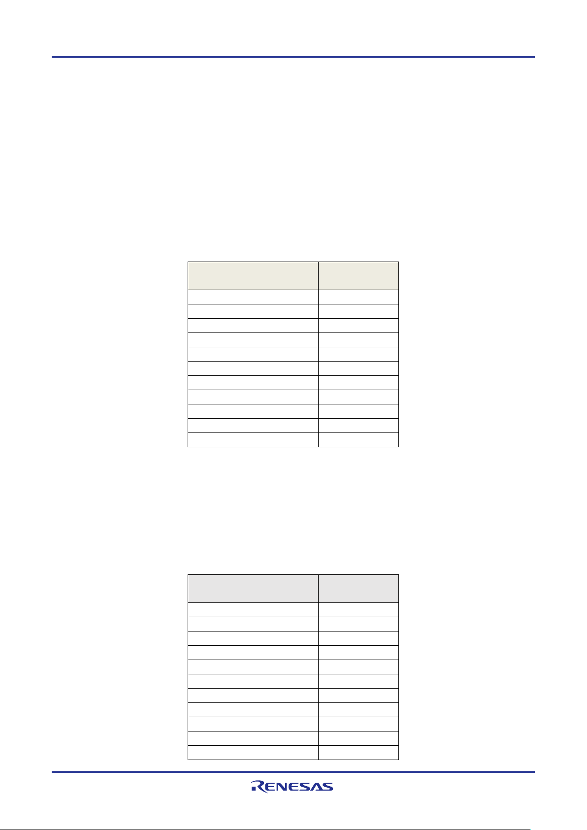
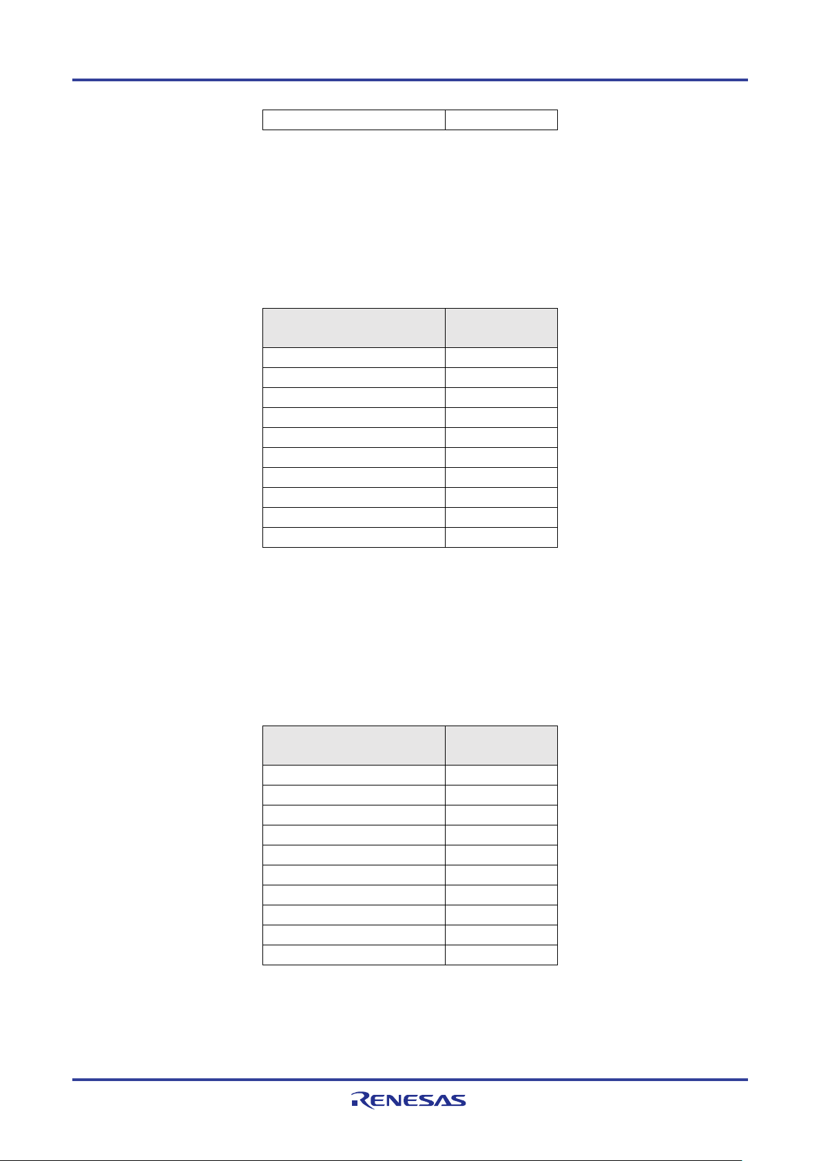
Related documents
The related documents indicated in this publication may include preliminary versions. However, preliminary versions are
not marked as such.
Document Name Document No.
Bluetooth Low Energy Protocol Stack
User's Manual This manual
API Reference Manual : Basics R01UW0088E
API Reference Manual : FMP R01UW0089E
API Reference Manual : PXP R01UW0090E
API Reference Manual : HTP R01UW0091E
API Reference Manual : BLP R01UW0092E
API Reference Manual : HOGP R01UW0093E
API Reference Manual : ScPP R01UW0094E
API Reference Manual : HRP R01UW0097E
API Reference Manual : CSCP R01UW0098E
API Reference Manual : CPP R01UW0099E
API Reference Manual : GLP R01UW0103E
API Reference Manual : TIP R01UW0106E
API Reference Manual : RSCP R01UW0107E
API Reference Manual : ANP R01UW0108E
API Reference Manual : PASP R01UW0109E
API Reference Manual : LNP R01UW0113E
Application Note : Sample Program R01AN1375E
Application Note : rBLE Command Specification R01AN1376E
Page 5

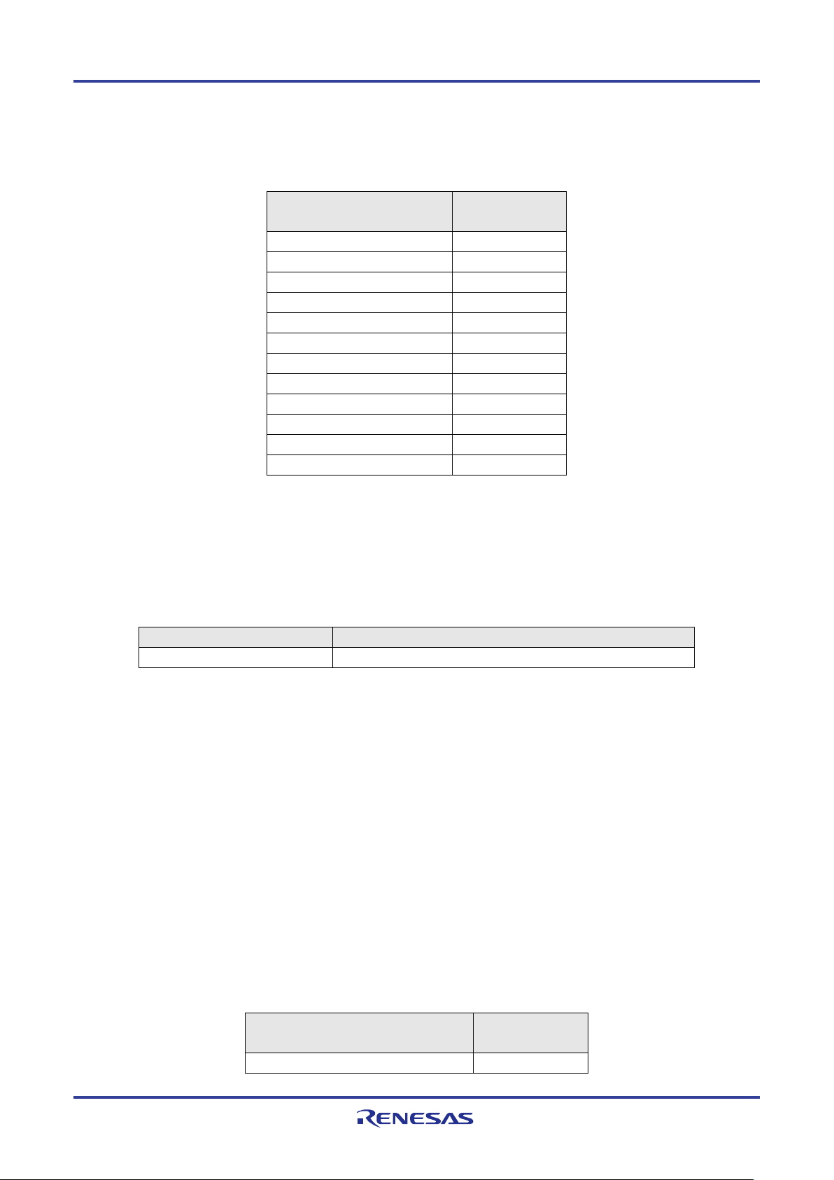
List of Abbreviations and Acronyms
Abbreviation Full Form Remark
ANP Alert Notification Profile
ANS Alert Notification Service
API Application Programming Interface
ATT Attribute Protocol
BAS Battery Service
BB Base Band
BD_ADDR Bluetooth Device Address
BLE Bluetooth low energy
BLP Blood Pressure Profile
BLS Blood Pressure Service
CPP Cycling Power Profile
CPS Cycling Power Service
CSCP Cycling Speed and Cadence Profile
CSCS Cycling Speed and Cadence Service
CSRK Connection Signature Resolving Key
CTS Current Time Service
DIS Device Information Service
EDIV Encrypted Diversifier
FMP Find Me Profile
GAP Generic Access Profile
GATT Generic Attribute Profile
GLP Glucose Profile
GLS Glucose Service
HCI Host Controller Interface
HID Human Interface Device
HIDS HID Service
HOGP HID over GATT Profile
HRP Heart Rate Profile
HRS Heart Rate Service
HTP Health Thermometer Profile
HTS Health Thermometer Service
IAS Immediate Alert Service
IRK Identity Resolving Key
L2CAP Logical Link Control and Adaptation Protocol
LE Low Energy
LL Link Layer
Page 6

Abbreviation Full Form Remark
LLS Link Loss Service
LNP Location and Navigation Profile
LNS Location and Navigation Service
LTK Long Term Key
MCU Micro Controller Unit
MITM Man-in-the-middle
MTU Maximum Transmission Unit
OOB Out of Band
OS Operating System
PASP Phone Alert Status Profile
PASS Phone Alert Status Service
PXP Proximity Profile
RF Radio Frequency
RSCP Running Speed and Cadence Profile
RSCS Running Speed and Cadence Service
RSSI Received Signal Strength Indication
ScPP Scan Parameters Profile
ScPS Scan Parameters Service
SM Security Manager
SMP Security Manager Protocol
STK Short Term Key
TK Temporary Key
TPS Tx Power Service
UART Universal Asynchronous Receiver Transmitter
UUID Universal Unique Identifier
Abbreviation Full Form Remark
APP Application
CSI Clocked Serial Interface
IIC Inter-Integrated Circuit
RSCIP Renesas Serial Communication Interface Protocol
VS Vendor Specific
Page 7

These commodities, technology or software, must be exported in accordance with the export administration regulations
of the exporting country. Diversion contrary to the law of that country is prohibited.
All trademarks and registered trademarks are the property of their respective owners.
Bluetooth is a registered trademark of Bluetooth SIG, Inc. U.S.A.
EEPROM is a trademark of Renesas Electronics Corporation.
Windows, Windows NT and Windows XP are registered trademarks or trademarks of Microsoft Corporation in the
United States and/or other countries.
PC/AT is a trademark of International Business Machines Corporation.
Page 8

Contents
1.
Overview ........................................................................................................................................................ 1
2. Applicability .................................................................................................................................................... 2
3. Restrictions .................................................................................................................................................... 3
4. Installing BLE Software ................................................................................................................................. 4
4.1 Components Included ......................................................................................................................................... 4
4.2 BLE software build environment ........................................................................................................................ 4
4.3 Installation Procedure ......................................................................................................................................... 5
4.4 Folder Organization ............................................................................................................................................ 7
4.4.1 \Renesas\BLE_Software_Ver_X_XX\Manual\ ......................................................................................... 7
4.4.2 \Renesas\BLE_Software_Ver_X_XX\RL78_G1D .................................................................................... 7
4.4.3 \Renesas\BLE_Software_Ver_X_XX\BLE_Sample\ .............................................................................. 15
5. BLE Software Configuration ........................................................................................................................ 16
5.1 Configuration .................................................................................................................................................... 16
5.2 rBLE API .......................................................................................................................................................... 18
5.3 RL78/G1D Hardware Resources used by the BLE Software ........................................................................... 20
5.4 Serial Communication in Modem Configuration .............................................................................................. 21
5.4.1 UART 2-wire Connection ........................................................................................................................ 23
5.4.2 UART 3-wire Connection ........................................................................................................................ 24
5.4.3 UART 2-wire with Branch Connection ................................................................................................... 29
5.4.4 CSI 4-wire Connection ............................................................................................................................ 31
5.4.5 CSI 5-wire Connection ............................................................................................................................ 35
5.4.6 IIC 3-wire Connection ............................................................................................................................. 39
5.5 Customer-specific information ......................................................................................................................... 43
5.6 Selection of own Bluetooth Device address ..................................................................................................... 43
6. Creating Executable Files............................................................................................................................ 44
6.1 Changing the Configuration Parameters ........................................................................................................... 44
6.1.1 Maximum Number of Simultaneous Connections ................................................................................... 46
6.1.2 Allocating the Heap Area ........................................................................................................................ 47
6.1.3 Changing the Operating Frequency ......................................................................................................... 47
6.1.4 Setting MCU part initialization ................................................................................................................ 48
6.1.5 Setting RF part initialization .................................................................................................................... 49
Index-1
Page 9

6.1.6 Selecting the serial communication method ............................................................................................ 51
6.1.7 Setting the UART baud rate ..................................................................................................................... 53
6.1.8 Setting the CSI baud rate ......................................................................................................................... 58
6.1.9 Setting the IIC transfer clock ................................................................................................................... 58
6.1.10 Wait for the time Sub Clock is stabled .................................................................................................... 58
6.1.11 Setting the Profile Service ....................................................................................................................... 58
6.2 Building a Project ............................................................................................................................................. 70
6.3 Additional Note ................................................................................................................................................ 71
7. Description of Features ............................................................................................................................... 72
7.1 Controller Stack ................................................................................................................................................ 72
7.1.1 Advertising .............................................................................................................................................. 72
7.1.2 Scanning .................................................................................................................................................. 73
7.1.3 Initiating ................................................................................................................................................... 74
7.1.4 White List ................................................................................................................................................ 74
7.2 Generic Access Profile ...................................................................................................................................... 76
7.2.1 GAP roles ................................................................................................................................................ 76
7.2.2 GAP modes and procedures ..................................................................................................................... 76
7.2.3 Security .................................................................................................................................................... 79
7.2.4 Bluetooth Device Address ....................................................................................................................... 80
7.2.5 Advertising and Scan response data formats ........................................................................................... 81
7.2.6 GAP Service for GATT Server ................................................................................................................ 85
7.3 Security Manager .............................................................................................................................................. 86
7.3.1 Pairing feature exchange .......................................................................................................................... 87
7.3.2 STK generation ........................................................................................................................................ 88
7.3.3 Key distribution ....................................................................................................................................... 90
7.4 Generic Attribute Profile .................................................................................................................................. 92
7.4.1 GATT Database ....................................................................................................................................... 93
7.4.2 Creating a User Profile ............................................................................................................................ 98
7.4.3 GATT Service ........................................................................................................................................ 101
7.5 Find Me Profile ............................................................................................................................................... 102
7.5.1 Use case implemented by using the Immediate Alert service ................................................................ 102
7.6 Proximity Profile ............................................................................................................................................ 104
7.6.1 Use case implemented by using the Link Loss service .......................................................................... 104
7.6.2 Use case implemented by using the Immediate Alert service and the Tx Power service ...................... 105
7.7 Health Thermometer Profile ........................................................................................................................... 106
7.7.1 Use case implemented by using the Health Thermometer service and the Device Information service 106
7.8 Blood Pressure Profile .................................................................................................................................... 108
Index-2
Page 10

7.8.1 Use case implemented by using the Blood Pressure service and the Device Information service ......... 108
7.9 HID over GATT Profile .................................................................................................................................. 110
7.9.1 Use case implemented by using the HID service ................................................................................... 110
7.9.2 Use case implemented by using the Device Information service ........................................................... 113
7.9.3 Use case implemented by using the Battery service .............................................................................. 113
7.9.4 Restrictions ............................................................................................................................................ 113
7.10 Scan Parameters Profile .................................................................................................................................. 114
7.10.1 Use case implemented by using the Scan Parameters service ............................................................... 114
7.11 Heart Rete Profile ........................................................................................................................................... 116
7.11.1 Use case implemented by using the Heart Rate service and the Device Information service ................ 116
7.12 Cycling Speed and Cadence Profile ................................................................................................................ 117
7.12.1 Use case implemented by using the Cycling Speed and Cadence service and the Device Information
service .................................................................................................................................................... 117
7.12.2 Use case implemented by using the SC Control Point characteristic..................................................... 118
7.13 Cycling Power Profile ..................................................................................................................................... 119
7.13.1 Use case implemented by using the Cycling Power service, the Device Information service and the
Battery service ....................................................................................................................................... 119
7.13.2 Use case implemented by using the Cycling Power Control Point characteristic .................................. 121
7.13.3 Use case implemented by Broadcaster role and Observer role .............................................................. 122
7.14 Glucose Profile ............................................................................................................................................... 123
7.14.1 Use case implemented by using the Glucose service and the Device Information service .................... 123
7.14.2 Use case implemented by using the Record Access Control Point characteristic .................................. 124
7.15 Time Profile .................................................................................................................................................... 125
7.15.1 Use case implemented by using the Current Time service .................................................................... 125
7.15.2 Use case implemented by using the Next DST Change service ............................................................ 125
7.15.3 Use case implemented by using the Reference Time Update service .................................................... 126
7.16 Running Speed and Cadence Profile ............................................................................................................... 127
7.16.1 Use case implemented by using the Running Speed and Cadence service and the Device Information
service .................................................................................................................................................... 127
7.16.2 Use case implemented by using the SC Control Point characteristic..................................................... 128
7.17 Alert Notification Profile ................................................................................................................................ 129
7.17.1 Use case implemented by using the Alert Notification service ............................................................. 129
7.17.2 Use case implemented by using the Alert Notification Control Point characteristic ............................. 130
7.18 Phone Alert Status Profile ............................................................................................................................... 131
7.18.1 Use case implemented by using the Phone Alert Status service ............................................................ 131
7.18.2 Use case implemented by using the Ringer Control Point characteristic ............................................... 131
7.19 Location and Navigation Profile ..................................................................................................................... 133
Index-3
Page 11

7.19.1 Use case implemented by using the Location and Navigation service, the Device Information service and
the Battery service ................................................................................................................................. 133
7.19.2 Use case implemented by using the LN Control Point characteristic .................................................... 134
7.20 Vendor Specific .............................................................................................................................................. 136
7.20.1 Peak current consumption notification .................................................................................................. 136
7.20.2 Sleep ...................................................................................................................................................... 138
7.20.3 Reset processing .................................................................................................................................... 138
7.20.4 Original features provided by rBLE API ............................................................................................... 139
8. EEPEOM Emulation Library ...................................................................................................................... 143
8.1 About the EEPROM Emulation Library ......................................................................................................... 143
8.2 About setting for the EEPROM emulation library .......................................................................................... 143
8.3 Notes on using the EEPROM emulation library ............................................................................................. 143
9. Code Flash Library .................................................................................................................................... 144
9.1 About the Code Flash Library......................................................................................................................... 144
9.2 About setting for the Code Flash library ......................................................................................................... 144
9.3 Notes on using the Code Flash library ............................................................................................................ 144
10. Note on Writing User Application .............................................................................................................. 145
10.1 Note on RWKE Timer Management Function ............................................................................................... 145
10.2 Interrupt disabled time of the task and the interrupt handler .......................................................................... 145
10.3 Data transmission of large size data ................................................................................................................ 145
10.4 Performance of BLE MCU ............................................................................................................................. 145
10.4.1 Modem Configuration............................................................................................................................ 145
11. Implementation of FW Update Feature ..................................................................................................... 147
11.1 The FW Update Feature .................................................................................................................................. 147
11.2 Function required for FW Update ................................................................................................................... 147
11.2.1 Writing function to the code flash ......................................................................................................... 147
11.2.2 Data transmission and reception profile ................................................................................................. 147
11.2.3 Application for update control (for Receiver device) ............................................................................ 149
11.2.4 Application for update control (for Sender device) ............................................................................... 150
11.3 Limitation and Special Processing .................................................................................................................. 151
11.3.1 Area switching control ........................................................................................................................... 151
11.3.2 Update the standard library (IAR Embedded Workbench only) ............................................................ 151
11.3.3 Limitation for FW Update feature implementation ............................................................................... 152
11.3.4 Update target area and User RAM area ................................................................................................. 153
Index-4
Page 12

12. HCI Packet Monitoring Feature ................................................................................................................. 155
12.1 Functional Composition of the HCI Packet Monitoring ................................................................................. 155
12.2 Enabling the HCI Packet Monitoring Feature ................................................................................................. 156
12.3 How to Use the HCI Packet Monitoring Feature ............................................................................................ 156
12.3.1 Preparations ........................................................................................................................................... 156
12.3.2 How to Use ............................................................................................................................................ 157
12.4 HCI Packet Monitoring Screen ....................................................................................................................... 158
Appendix A Referenced Documents ................................................................................................................ 159
Appendix B Terminology................................................................................................................................... 160
Index-5
Page 13

Bluetooth Low Energy Protocol Stack
User
’s Manual
R01UW0095EJ0122
Rev.1.22
Mar. 30, 2018
1. Overview
This manual describes the API (Application Program Interface) of the basic features of the Bluetooth Low Energy
protocol stack (BLE software), which is used to develop Bluetooth applications that incorporate Renesas Bluetooth low
energy microcontroller RL78/G1D.
For details about the BLE software APIs, see Bluetooth Low Energy Protocol Stack API Reference Manual.
R01UW0095EJ0122 Rev.1.22 Page 1 of 162
Mar. 30, 2018
Page 14

2. Applicability
2. Applicability
The descriptions in this manual apply to Bluetooth Low Energy protocol stack Version 1.21 or later.
R01UW0095EJ0122 Rev.1.22 Page 2 of 162
Mar. 30, 2018
Page 15

3. Restrictions
3. Restrictions
This section describes the restrictions that apply to BLE software.
R01UW0095EJ0122 Rev.1.22 Page 3 of 162
Mar. 30, 2018
Page 16

4. Installing BLE Software
4. Installing BLE Software
4.1 Components Included
The compressed package of the BLE software includes the followings:
• Documents
- Bluetooth Low Energy Protocol Stack User's Manual (this document)
- Bluetooth Low Energy Protocol Stack API Reference Manual
- Bluetooth Low Energy Protocol Stack Sample Program Application Note
- rBLE command specifications
• Project files used for creating the executable file
- Executable file
- BLE software library
- Sample source code
- Source code that configures parameters
2
studio project file
- e
- CS+ for CC project file
- CS+ for CA,CX project file
- IAR Embedded Workbench workspace file
• Sample applications for computer
- Executable file
- Source code
- Microsoft Visual Studio Express 2015 project file
• HCI packet monitor application for computer
- Executable file
- INI file
4.2 BLE software build environment
The environment in which BLE software was built is shown below.
• Hardware environment
- Host
• PC/AT™-compatible computer
• Processor : At least 1.6 GHz
• Main memory : At least 1 GB
• Display : 1024 x 768 or higher resolution and 65,536 colors
• Interface : USB 2.0 (E1 and USB-serial conversion cable)
• Tools used
• Renesas on-chip debugging emulator E1
• Software environment
• Windows 7 or later
• Microsoft Visual Studio Express 2015 for Desktop
R01UW0095EJ0122 Rev.1.22 Page 4 of 162
Mar. 30, 2018
Page 17

4. Installing BLE Software
• Microsoft .NET Framework 4 + language pack
• Renesas CS+ for CC V4.00.00/ RL78 Compiler CC-RL V1.03.00
or e² studio 4.3.1.001/RL78 Family C Compiler Package V1 (without IDE) V1.03.00
or Renesas CS+ for CA, CX V3.02.00/Renesas CA78K0R V1.72
or IAR Embedded Workbench for Renesas RL78 V2.20.1
• Renesas Flash Programmer V3
(available from https://www.renesas.com/software-tool/renesas-flash-programmer-programming-gui)
For details about the environment in which to run the sample application for computers, see Bluetooth Low Energy
Protocol Stack Sample Program Application Note.
4.3 Installation Procedure
Copy the decompressed contents of the package to any folder in your computer.
2
Note: If using the e
To build the BLE software, the EEPROM Emulation Library and Code Flash Library are needed. Libraries for testing are
contained in the BLE software package in advance. But when you start to develop a product, it is necessary to download the
newest libraries corresponding to your development environment from Renesas website and copy to the following folder.
The EEPROM Emulation Library and Code Flash Library are provided by Renesas Electronics Corporation. Regarding
how to install the libraries, refer to 4.4.2 (7) and 4.4.2 (8).
EEPROM Emulation Library and Data Flash Access Library
- CS+ for CC/e
\Renesas\BLE_Software_Ver_X_XX\RL78_G1D\Project_Source\renesas\src\driver\dataflash\cc_rl
- CS+ for CA,CX
\Renesas\BLE_Software_Ver_X_XX\RL78_G1D\Project_Source\renesas\src\driver\dataflash\cs
- IAR V2.20.1
\Renesas\BLE_Software_Ver_X_XX\RL78_G1D\Project_Source\renesas\src\driver\dataflash\iar_v2
Code Flash Library
- CS+ for CC/e
\Renesas\BLE_Software_Ver_X_XX\RL78_G1D\Project_Source\renesas\src\driver\codeflash\cc_rl
- CS+ for CA,CX
\Renesas\BLE_Software_Ver_X_XX\RL78_G1D\Project_Source\renesas\src\driver\codeflash\cs
- IAR V2.20.1
\Renesas\BLE_Software_Ver_X_XX\RL78_G1D\Project_Source\renesas\src\driver\codeflash\iar_v2
Note that the following versions of the library are included in the BLE software package:
EEPROM Emulation Library and Data Flash Access Library
studio, you cannot use multi-byte characters or blank in the BLE software installation folder path.
2
studio (CC-RL)
2
studio (CC-RL)
- for all compilers
"EEPROM Emulation Library Pack02 Package Ver.2.00(for CA78K0R/CC-RL Compiler) for RL78 Family"
Code Flash Library
R01UW0095EJ0122 Rev.1.22 Page 5 of 162
Mar. 30, 2018
Page 18

4. Installing BLE Software
- for all compilers
" Flash Self Programming Library Type01 Package Ver.3.00 for the RL78 Family [for the CA78K0R/CC-RL
Compiler]"
R01UW0095EJ0122 Rev.1.22 Page 6 of 162
Mar. 30, 2018
Page 19
Folder name
Name of the executable file
Content
\ca78k0r
Folder for CS+ for CA,CX
\Embedded
Folder for Embedded configuration
Proximity / Find Me / Alert Notification Profile
over GATT / Scan Parameters
Profile
Speed and Cadence / Cycling Power Profile
Cadence Profile
Glucose / Phone Alert Status / Time Profile
Sample program.
Custom Profile
\Modem
Folder for Modem configuration
Proximity / Find Me / Alert Notification Profile
4. Installing BLE Software
4.4 Folder Organization
The detail of file and folder after installation is shown below.
4.4.1 \Renesas\BLE_Software_Ver_X_XX\Manual\
This folder includes the manuals. Please read them before using the product.
4.4.2 \Renesas\BLE_Software_Ver_X_XX\RL78_G1D
(1) \ROM_File\
This folder contains the executable files (hex files) of the BLE software programs that run on the RL78/G1D. Write these
programs to the RL78/G1D on-chip flash memory.
For how to write to the on-chip flash memory, see the Renesas Flash Programmer flash memory programming software
User's Manual.
Also, if you have already written the BD address into on-chip data flash memory, change the operation mode of the RFP
software configuration information list to "block (code flash)". If you don't, the written BD address might be erased.
The contents of the executable file that is stored in this folder are shown in Table 4-1 . See a section 6 Creating
Executable Files about Sample Custom profile. See Bluetooth Low Energy Protocol Stack Application Note: Sample
Program about how to create an executable file.
Table 4-1 Overview of the executable file
RL78_G1D_CE(PXP,FMP,ANP).hex Executable file that corresponds to the
RL78_G1D_CE(HOGP,ScPP).hex Executable file that corresponds to the HID
RL78_G1D_CE(HTP,BLP,HRP).hex Executable file that corresponds to the Health
Thermometer / Blood Pressure / Heart Rate
RL78_G1D_CE(CSCP,CPP).hex Executable file that corresponds to the Cycling
RL78_G1D_CE(LNP,RSCP).hex Executable file that corresponds to the
Location and Navigation / Running Speed and
RL78_G1D_CE(GLP,PASP,TIP).hex Executable file that corresponds to the
RL78_G1D_CE(SCP).hex Executable file that corresponds to the Simple
RL78_G1D_CE(SIMPLE_SAMPLE).hex Executable file that corresponds to the Sample
RL78_G1D_CM(PXP,FMP,ANP).hex Executable file that corresponds to the
R01UW0095EJ0122 Rev.1.22 Page 7 of 162
Mar. 30, 2018
Page 20
Folder name
Name of the executable file
Content
over GATT / Scan Parameters
Profile
Speed and Cadence / Cycling Power Profile
Cadence Profile
Glucose / Phone Alert Status / Time Profile
Custom Profile
UART Direct Test Mode
\ccrl
Folder for CC-RL
\Embedded
Folder for Embedded configuration
Proximity / Find Me / Alert Notification Profile
over GATT / Scan Parameters
Profile
Speed and Cadence / Cycling Power Profile
Cadence Profile
Glucose / Phone Alert Status / Time Profile
Custom Profile
Custom Profile
\Modem
Folder for Modem configuration
Proximity / Find Me / Alert Notification Profile
over GATT / Scan Parameters
Profile
Speed and Cadence / Cycling Power Profile
4. Installing BLE Software
RL78_G1D_CM(HOGP,ScPP).hex Executable file that corresponds to the HID
RL78_G1D_CM(HTP,BLP,HRP).hex Executable file that corresponds to the Health
Thermometer / Blood Pressure / Heart Rate
RL78_G1D_CM(CSCP,CPP).hex Executable file that corresponds to the Cycling
RL78_G1D_CM(LNP,RSCP).hex Executable file that corresponds to the
Location and Navigation / Running Speed and
RL78_G1D_CM(GLP,PASP,TIP).hex Executable file that corresponds to the
RL78_G1D_CM(SCP).hex Executable file that corresponds to the Sample
RL78_G1D_CM(DTM_2WIRE).hex Executable file that corresponds to 2-Wire
RL78_G1D_CE(PXP,FMP,ANP).hex Executable file that corresponds to the
RL78_G1D_CE(HOGP,ScPP).hex Executable file that corresponds to the HID
RL78_G1D_CE(HTP,BLP,HRP).hex Executable file that corresponds to the Health
Thermometer / Blood Pressure / Heart Rate
RL78_G1D_CE(CSCP,CPP).hex Executable file that corresponds to the Cycling
RL78_G1D_CE(LNP,RSCP).hex Executable file that corresponds to the
Location and Navigation / Running Speed and
RL78_G1D_CE(GLP,PASP,TIP).hex Executable file that corresponds to the
RL78_G1D_CE(SCP).hex Executable file that corresponds to the Sample
RL78_G1D_CCE(SIMPLE_SAMPLE).hex Executable file that corresponds to the Sample
RL78_G1D_CM(PXP,FMP,ANP).hex Executable file that corresponds to the
RL78_G1D_CM(HOGP,ScPP).hex Executable file that corresponds to the HID
RL78_G1D_CM(HTP,BLP,HRP).hex Executable file that corresponds to the Health
RL78_G1D_CM(CSCP,CPP).hex Executable file that corresponds to the Cycling
R01UW0095EJ0122 Rev.1.22 Page 8 of 162
Mar. 30, 2018
Thermometer / Blood Pressure / Heart Rate
Page 21
Folder name
Name of the executable file
Content
Cadence Profile
Glucose / Phone Alert Status / Time Profile
Custom Profile
\iar_v2
Folder for IAR Embedded Workbench V2
\Embedded
Folder for Embedded configuration
Proximity / Find Me / Alert Notification Profile
over GATT / Scan Parameters
Profile
Speed and Cadence / Cycling Power Profile
Cadence Profile
Glucose / Phone Alert Status / Time Profile
Custom Profile
Custom Profile
\Modem
Folder for Modem configuration
Proximity / Find Me / Alert Notification Profile
over GATT / Scan Parameters
Profile
Speed and Cadence / Cycling Power Profile
Cadence Profile
Glucose / Phone Alert Status / Time Profile
Custom Profile
4. Installing BLE Software
RL78_G1D_CM(LNP,RSCP).hex Executable file that corresponds to the
Location and Navigation / Running Speed and
RL78_G1D_CM(GLP,PASP,TIP).hex Executable file that corresponds to the
RL78_G1D_CM(SCP).hex Executable file that corresponds to the Sample
RL78_G1D_IE(PXP,FMP,ANP).hex Executable file that corresponds to the
RL78_G1D_IE(HOGP,ScPP).hex Executable file that corresponds to the HID
RL78_G1D_IE(HTP,BLP,HRP).hex Executable file that corresponds to the Health
Thermometer / Blood Pressure / Heart Rate
RL78_G1D_IE(CSCP,CPP).hex Executable file that corresponds to the Cycling
RL78_G1D_IE(LNP,RSCP).hex Executable file that corresponds to the
Location and Navigation / Running Speed and
RL78_G1D_IE(GLP,PASP,TIP).hex Executable file that corresponds to the
RL78_G1D_IE(SCP).hex Executable file that corresponds to the Sample
RL78_G1D_IE(SIMPLE_SAMPLE).hex Executable file that corresponds to the Sample
RL78_G1D_IM(PXP,FMP,HTP,BLP).hex Executable file that corresponds to the
RL78_G1D_IM(HOGP,ScPP).hex Executable file that corresponds to the HID
RL78_G1D_IM(HTP,BLP,HRP).hex Executable file that corresponds to the Health
Thermometer / Blood Pressure / Heart Rate
RL78_G1D_IM(CSCP,CPP).hex Executable file that corresponds to the Cycling
RL78_G1D_IM(LNP,RSCP).hex Executable file that corresponds to the
RL78_G1D_IM(GLP,PASP,TIP).hex Executable file that corresponds to the
RL78_G1D_IM(SCP).hex Executable file that corresponds to the Sample
The setting for building each executable file in this folder is shown as follows. Regarding the setting of profiles, refer to
the subsection 6.1.11.1 "Profile Enable / Disable Setting" in this document.
R01UW0095EJ0122 Rev.1.22 Page 9 of 162
Mar. 30, 2018
Location and Navigation / Running Speed and
Page 22
profiles in prf_sel.h
PRF_SEL_PXPM
(1)(0)
PRF_SEL_PXPR
(1)(0)
PRF_SEL_FMPL
(1)(0)
PRF_SEL_FMPT
(1)(0)
PRF_SEL_HGHD
(0)(1)
PRF_SEL_HGBH
(0)(1)
PRF_SEL_HGRH
(0)(1)
PRF_SEL_SPPC
(0)(1)
PRF_SEL_SPPS
(0)(1)
PRF_SEL_ANPC
(1)(0)
PRF_SEL_ANPS
(1)(0)
profiles in prf_sel.h
PRF_SEL_PXPM
(1)(0)
PRF_SEL_PXPR
(1)(0)
PRF_SEL_FMPL
(1)(0)
PRF_SEL_FMPT
(1)(0)
PRF_SEL_HTPC
(0)(1)
PRF_SEL_HTPT
(0)(1)
PRF_SEL_BLPC
(0)(1)
PRF_SEL_BLPS
(0)(1)
PRF_SEL_HRPC
(0)(1)
PRF_SEL_HRPS
(0)(1)
PRF_SEL_ANPC
(1)(0)
4. Installing BLE Software
Build setting for RL78_G1D_xx(PXP,FMP,ANP).hex
Project files to build this executable file are included in the following folder. There is no change from default setting.
Project folder: \Project_Source\renesas\tools\project\
Build setting for RL78_G1D_xx(HOGP,ScPP).hex
Project files to build this executable file are included in the following folder.
Project folder: \Project_Source\renesas\tools\project\
To enable HOGP and ScPP, the following macro setting change is needed.
Configuration file: Project_Source\renesas\src\arch\rl78\prf_sel.h
Table 4-2 Profile setting for RL78_G1D_xx(HOGP,ScPP).hex
Setting Macros for selecting
Changes
Build setting for RL78_G1D_xx(HTP,BLP,HRP).hex
Project files to build this executable file are included in the following folder.
Project folder: \Project_Source\renesas\tools\project\
To enable HTP,BLP and HRP, the following macro setting change is needed.
Configuration file: Project_Source\renesas\src\arch\rl78\prf_sel.h
Table 4-3 Profile setting for RL78_G1D_xx(HTP,BLP,HRP).hex
Setting Macros for selecting
Changes
R01UW0095EJ0122 Rev.1.22 Page 10 of 162
Mar. 30, 2018
Page 23
PRF_SEL_ANPS
(1)(0)
profiles in prf_sel.h
PRF_SEL_PXPM
(1)(0)
PRF_SEL_PXPR
(1)(0)
PRF_SEL_FMPL
(1)(0)
PRF_SEL_FMPT
(1)(0)
PRF_SEL_CSCC
(0)(1)
PRF_SEL_CSCS
(0)(1)
PRF_SEL_CPPC
(0)(1)
PRF_SEL_CPPS
(0)(1)
PRF_SEL_ANPC
(1)(0)
PRF_SEL_ANPS
(1)(0)
profiles in prf_sel.h
PRF_SEL_PXPM
(1)(0)
PRF_SEL_PXPR
(1)(0)
PRF_SEL_FMPL
(1)(0)
PRF_SEL_FMPT
(1)(0)
PRF_SEL_ANPC
(1)(0)
PRF_SEL_ANPS
(1)(0)
PRF_SEL_LNPS
(0)(1)
PRF_SEL_LNPC
(0)(1)
PRF_SEL_RSCC
(0)(1)
PRF_SEL_RSCS
(0)(1)
4. Installing BLE Software
Build setting for RL78_G1D_xx(CSCP,CPP).hex
Project files to build this executable file are included in the following folder.
Project folder: \Project_Source\renesas\tools\project\
To enable CSCP and CPP, the following macro setting change is needed.
Configuration file: Project_Source\renesas\src\arch\rl78\prf_sel.h
Table 4-4 Profile setting for RL78_G1D_xx(CSCP,CPP).hex
Setting Macros for selecting
Changes
Build setting for RL78_G1D_xx(LNP,RSCP).hex
Project files to build this executable file are included in the following folder.
Project folder: \Project_Source\renesas\tools\project\
To enable LNP and RSCP, the following macro setting change is needed.
Configuration file: Project_Source\renesas\src\arch\rl78\prf_sel.h
Table 4-5 Profile setting for RL78_G1D_xx(LNP,RSCP).hex
Setting Macros for selecting
Changes
Build setting for RL78_G1D_xx(GLP,PASP,TIP).hex
Project files to build this executable file are included in the following folder.
Project folder: \Project_Source\renesas\tools\project\
R01UW0095EJ0122 Rev.1.22 Page 11 of 162
Mar. 30, 2018
Page 24
profiles in prf_sel.h
PRF_SEL_PXPM
(1)(0)
PRF_SEL_PXPR
(1)(0)
PRF_SEL_FMPL
(1)(0)
PRF_SEL_FMPT
(1)(0)
PRF_SEL_GLPC
(0)(1)
PRF_SEL_GLPS
(0)(1)
PRF_SEL_TIPC
(0)(1)
PRF_SEL_TIPS
(0)(1)
PRF_SEL_ANPC
(1)(0)
PRF_SEL_ANPS
(1)(0)
PRF_SEL_PASC
(0)(1)
PRF_SEL_PASS
(0)(1)
Compile Option
Changes
Preprocessor Macro Definition
noUSE_SAMPLE_PROFILE USE_SAMPLE_PROFILE
rwble_config.h
__DTM2WIRE_UART_USE__
(0)(1)
4. Installing BLE Software
To enable GLP,PASP and TIP, the following setting change is needed.
Configuration file: Project_Source\renesas\src\arch\rl78\prf_sel.h
Table 4-6 Profile setting for RL78_G1D_xx(GLP,PASP,TIP).hex
Setting Macros for selecting
Changes
Build setting for RL78_G1D_xx(SCP).hex
Project files to build this executable file are included in the following folder.
Project folder: \Project_Source\renesas\tools\project\
To enable Custom Profile, the following compile option setting change is needed.
Table 4-7 Profile setting for RL78_G1D_xx(SCP).hex
Build setting for RL78_G1D_xx(SIMPLE_SAMPLE).hex
Project files to this build executable file are included in the following folder. There is no need to change source code or
project setting.
Project Folder: \Project_Source\renesas\tools\project_simple\
Regarding the the simple sample program, refer to chapter 6 "Usage of Simple Sample Program" in Bluetooth low
energy Protocol Stack Sample Program Application Note (R01AN1375).
Build setting for RL78_G1D_CM(DTM_2WIRE).hex
Project files to build this executable file are included in the following folder.
Project folder: \Project_Source\renesas\tools\project\
To enable Direct Test Mode by 2-wire UART, the following macro setting change is needed.
Configuration file: Project_Source\bleip\src\rwble\rwble_config.h
Table 4-8 DTM setting for RL78_G1D_CM(DTM_2WIRE).hex
Setting Macro for enabling DTM in
R01UW0095EJ0122 Rev.1.22 Page 12 of 162
Mar. 30, 2018
Changes
Page 25

4. Installing BLE Software
Regarding the Direct Test Mode sample program, refer to section 7.7 "Sample Program for the Direct Test Mode with RF
Tester" in Bluetooth low energy Protocol Stack Sample Program Application Note (R01AN1375).
(2) \Project_Source\
This folder contains the BLE software library and sample source code required for building the executable files (hex
files) of the software programs that run on the RL78/G1D.
(3) \Project_Source\renesas\tools\project\
This folder contains the project/workspace files for each development environment which are required for building the
executable files (hex files) of the software programs that run on the RL78/G1D. In addition, projects/workspaces in the
Embedded configuration and Modem configuration for each development environment are contained. Build the program
by using these project/workspace files in your development environment to generate executable files.
For how to build the program, see 6.2.
(4) \Project_Source\renesas\tools\project_devices\
This folder contains the project/workspace files for each development environment which are required for building the
executable files (hex files) for the R5F11AGG(128KB) and R5F11AGH(192KB). In addition, projects/workspaces in the
Embedded configuration and Modem configuration for each development environment are contained. Build the program
by using these project/workspace files in your development environment to generate executable files.
(5) \Project_Source\renesas\tools\project_simple\
This folder contains the project/workspace files for each development environment which are required for building the
executable files (hex files) of the simple sample program which shows how to use the BLE software. Build the program by
using these project/workspace files in your development environment to generate executable files.
For details about the simple sample program, see Sample Program Application Note (R01AN1375).
(6) \Project_Source\renesas\src\
This folder contains the files for configuring the parameters that can be changed by the user (source code). Change the
parameter settings as required before building the program.
For details about the configurable parameters and how to change the settings, see 6.1.
(7) \Project_Source\renesas\src\driver\dataflash\cc_rl\ or \cs\ or \iar_v2\
This folder is for containing the EEPROM Emulation Library and Data Flash Access Library to access Data Flash
memory. The libraries for testing are contained in advance. But when you start to develop a product, it is necessary to copy
the newest library corresponding to your development environment to this folder.
The EEPROM Emulation Library and Data Flash Access Library are downloaded from Renesas website. For reference,
shows how to obtain a tested version by the BLE software from Renesas website. In addition, operating procedures might
be changed without a notice by the renewals of the website.
Open the Renesas website (https://www.renesas.com/). Select [DESIGN & SUPPORT] [DEVELOPMENT TOOLS]
[Data Flash Libraries].
R01UW0095EJ0122 Rev.1.22 Page 13 of 162
Mar. 30, 2018
Page 26

4. Installing BLE Software
Get the following file and execute files for unzip the EEPROM Emulation Library and Data Flash Access Library.
• EEPROM Emulation Library Pack02 Package Ver.2.00(for CA78K0R/CC-RL Compiler) for RL78 Family.
Note: For the library for IAR, select "America/Europe/Middle East/Africa" when you run the installer. The Library
version select "IAR compiler version 2.10.
The files to be copied are shown below.
CS+ for CC or e
2
studio (CC-RL) version:
• eel.h
• eel.lib
• eel_types.h
• fdl.h
• fdl.lib
• fdl_types.h
CS+ for CA, CX version:
• eel.h
• eel.lib
• eel_types.h
• fdl.h
• fdl.lib
• fdl_types.h
IAR Embedded Workbench V2 version:
• eel.h
• eel.a
• eel_types.h
• fdl.h
• fdl.a
• fdl_types.h
(8) \Project_Source\renesas\src\driver\codeflash\cc_rl\ or cs\ or \iar_v2\
This folder is for containing the Code Flash Library to write to Code Flash memory. The library for testing is contained
in advance. But when you start to develop a product, it is necessary to copy the newest Code Flash Library corresponding to
your development environment to this folder.
The Code Flash Library is downloaded from Renesas website. For reference, shows how to obtain a tested version by the
BLE software from Renesas website. In addition, operating procedures might be changed without a notice by the renewals
of the website.
Open the Renesas website (https://www.renesas.com/). Select [DESIGN & SUPPORT] [DEVELOPMENT TOOLS]
[Code Flash Libraries].
Get the following file and execute file for unzip the Code Flash Library.
• Flash Self Programming Library Type01 Package Ver.3.00 for the RL78 Family [for the CA78K0R/CC-RL
Note: For the library for IAR, select "America/Europe/Middle East/Africa" when you run the installer. The Library
version select "IAR compiler version 2.10.
R01UW0095EJ0122 Rev.1.22 Page 14 of 162
Mar. 30, 2018
Compiler]
Page 27

4. Installing BLE Software
The files to be copied are shown below.
CS+ for CC or e
2
studio (CC-RL) version
• fsl.h
• fsl.lib
• fsl_types.h
CS+ for CA, CX version
• fsl.h
• fsl.lib
• fsl_types.h
IAR Embedded Workbench V2 version
• fsl.h
• fsl.a
• fsl_types.h
4.4.3 \Renesas\BLE_Software_Ver_X_XX\BLE_Sample\
This folder contains the executable files of the BLE software sample program that runs on a computer when BLE
software is used in the Modem configuration. About the detail of the sample program, see Bluetooth Low Energy Protocol
Stack Application Note: Sample Program.
R01UW0095EJ0122 Rev.1.22 Page 15 of 162
Mar. 30, 2018
Page 28
5. BLE Software Configuration
5. BLE Software Configuration
BLE software refers to the set of software that includes BLE stacks compliant with the Bluetooth Low Energy protocol
(Bluetooth v4.2). The following section describes the BLE software configuration in detail.
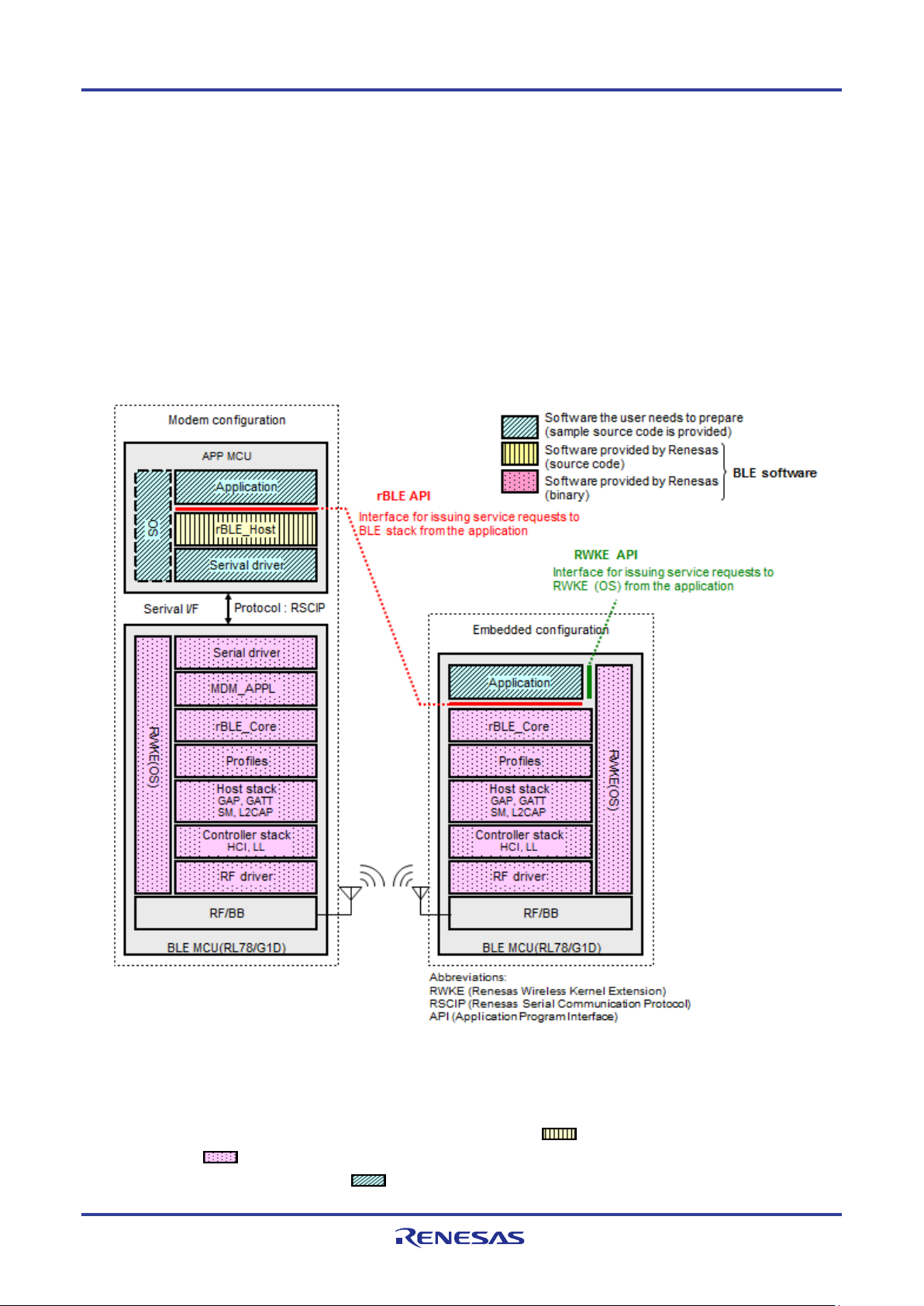
5.1 Configuration
Figure 5-1 shows the BLE software configuration.
BLE software runs in a configuration in which the application is mounted on the RL78/G1D (hereafter referred to as the
Embedded configuration) and in a configuration in which the application is mounted on another MCU (hereafter referred to
as the Modem configuration). BLE software provides APIs which can use the same application in both configurations.
Figure 5-1 BLE Software Configuration
BLE software in the Modem configuration runs on two chips, the APP MCU and the BLE MCU (RL78/G1D). BLE
software is configured of an rBLE_Host block that runs on the APP MCU (
on the BLE MCU (
The software to be prepared by the user (
R01UW0095EJ0122 Rev.1.22 Page 16 of 162
Mar. 30, 2018
blocks in the figure).
blocks in the figure) consists of the APP MCU’s application block, serial
block in the figure), and software that runs
Page 29
Block Name
Description
Application
Software the user needs to prepare
OS
Operating system the user needs to prepare
rBLE APIs from the application.
Note: The user needs to prepare this driver.
protocol.
stack services via rBLE_Core.
the profile layer to the RF driver).
Controller stack : LL and HCI
Kernel Extension)
other modules and manages the entire BLE MCU.
5. BLE Software Configuration
communication driver block, and OS block. However, if there is no OS in the APP MCU, software for the OS block does
not have to be prepared because the rBLE_Host block does not use resources of the OS.
The application that runs on the APP MCU executes communication between the BLE MCU and BLE services via
rBLE_Host. The APP MCU and BLE MCU are physically connected via UART or CSI or IIC, and communication is
executed using RSCIP (Renesas Serial Communication Interface Protocol) under the control of rBLE_Host.
BLE software in the Embedded configuration runs on only a single chip, the BLE MCU (RL78/G1D). The software to be
prepared by the user is only the application block and it should be implemented on the BLE MCU.
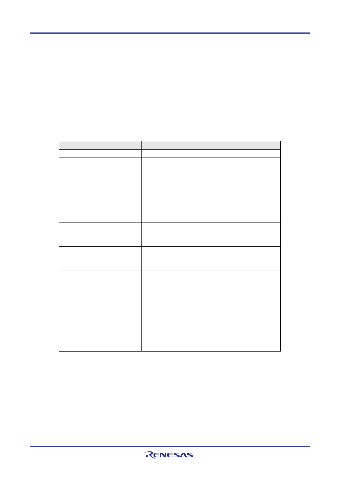
Table 5-1 gives an overview of the software blocks.
Table 5-1 Overview of Software Blocks
rBLE_Host Builds command packets for MDM_APPL and analyzes
event packets from MDM_APPL, enabling the issuance of
Serial Communication driver
(APP MCU)
Serial Communication driver
(BLE MCU)
MDM APPL Analyzes command packets from rBLE_Host and builds
rBLE_Core Provides an interface with the upstream modules for
Profile layer Main BLE stack
Host stack
Controller stack
RWKE (Renesas Wireless
Performs communication with the BLE MCU through
UART or CSI or IIC. RSCIP is used as the communication
protocol.
Performs communication with the APP MCU through
UART or CSI or IIC. RSCIP is used as the communication
event packets for rBLE_Host, enabling the use of BLE
using the services of the main BLE stack (the part from
Profiles : FMP, PXP, HTP, BLP, HOGP, ScPP, HRP,
CSCP, CPP, GLP, TIP, RSCP, ANP, PASP and LNP
Host stack : SM, L2CAP, GAP, and GATT
Provides the basic functionality used commonly with the
R01UW0095EJ0122 Rev.1.22 Page 17 of 162
Mar. 30, 2018
Page 30
SM
FMP
GAP
PXP
HTP
BLP
HOGP
ScPP
GATT
ATT
rBLE API
ANP
LNP
HRP
CSCP
CPP
GLP
TIP
RSCP
PASP
Layer
Description
Supported Features
Privacy feature
above.
encryption, and data signing
means of alerts.
be sent to the user.
5. BLE Software Configuration
5.2 rBLE API
The BLE software provides an API (rBLE API) that allows the application to use the services of the BLE stack on the
BLE MCU from the application.
The Bluetooth layers that can be accessed by the APIs provided by the rBLE API are shown in the figure below.
Figure 5-2 rBLE API and BLE Stack
The features supported by the various layers are listed in Table 5-2. For details about the various features, see 7
Description of Features.
Table 5-2 Bluetooth Features Supported by the rBLE API
GAP
(Generic Access
Profile)
SM
(Security Manager)
Executes access procedures
according to the link
management and security
requirements for processes
such as device discovery and
peer device connection and
disconnection.
Executes pairing between two
devices, communication
encryption, and data signing to
ensure security. Also executes
information exchange between
devices as needed for the
• Four GAP roles
(Central, Peripheral, Broadcaster, and Observer)
• Broadcast and Scan
• Discovery, Connection, and Bonding modes, and
procedures
• Security mode
• Connection and disconnection of a link
• Changing the connection parameters
• Random and static addresses
•
• Pairing procedure
• Pairing algorithms
(Passkey Entry, Just Works, OOB)
• Pairing and key generation
• Key distribution
• Security implemented by authentication,
FMP
(Find Me Profile)
PXP
(Proximity Profile)
R01UW0095EJ0122 Rev.1.22 Page 18 of 162
Mar. 30, 2018
Allows searching for peer
devices within the
communication range by
Defines the behavior when a
device moves away from a peer
device so that the connection is
dropped or the path loss
increases above a preset level,
causing an immediate alert to
• Immediate Alert service
• Link Loss service
• Immediate Alert service
• Tx Power service
Page 31

Layer
Description
Supported Features
Profile)
blood pressure sensor.
link.
reconnection latency.
sensor.
Cadence sensor (CSC sensor).
(CP sensor).
sensor.
from a server.
Reference Time Update service
Cadence Sensor (RSC Sensor)
Profile)
server.
5. BLE Software Configuration
HTP
(Health
Thermometer
BLP
(Blood Pressure
Profile)
HOGP
(HID over GATT
Profile)
ScPP
(Scan Parameters
Profile)
HRP
(Heart Rate Profile)
Used to enable a data
collection device to obtain data
from a thermometer sensor.
Used to enable a device to
obtain blood pressure
measurement data from a
Allows data communication
between an HID device and
HID host by adapting USB HID
to the operation on the BLE
Used to provide devices with
information to assist them in
managing their connection idle
timeout and advertising
parameters to optimize power
consumption and/or
Used to enable a device to
obtain data from a heart rate
• Health Thermometer service
• Device Information service
• Blood Pressure service
• Device Information service
• HID service
• Device Information service
• Battery service
• Scan Parameters service
• Heart Rate service
• Device Information service
CSCP
(Cycling Speed and
Cadence Profile)
CPP
(Cycling Power
Profile)
GLP
(Glucose Profile)
TIP
(Time Profile)
RSCP
(Running Speed and
Cadence Profile)
ANP
(Alert Notification
Used to enable a data
collection device to obtain data
from a Cycling Speed and
Used to enable a data
collection device to obtain data
from a Cycling Power sensor
Used to enable a device to
glucose measurement and
other data from a glucose
Used to obtain the date and
time, and related information
Used to enable a data
collection device to obtain data
from a Running Speed and
Used to enable a client to
obtain alert notification from a
• Cycling Speed and Cadence service
• Device Information service
• Cycling Power service
• Device Information service
• Battery service
• Glucose service
• Device Information service
• Current Time service
• Next DST Change service
•
• Running Speed and Cadence service
• Device Information service
• Alert Notification service
R01UW0095EJ0122 Rev.1.22 Page 19 of 162
Mar. 30, 2018
Page 32

Layer
Description
Supported Features
phone from a server.
Navigation Profile)
Navigation sensor (LN sensor).
Battery service
Configuration
Modem
Embedded
Data Flash Memory
Used
Used
Used to store the BD address.
circuit Note (3)
circuit Note (3)
circuit Note (3)
resonator.
Channel 7
Not Used
Used by CSI or IIC Driver ( Unit0 Channel7)
Note (4)
P30(input)
P30: Used by WAKEUP Driver for UART or CSI
UART1
CSI21
CSI21
CSI21 : Note (2)
Accumulator
(CS+ for CA,CX and IAR Embedded Workbench and
5. BLE Software Configuration
PASP
(Phone Alert Status
Profile)
LNP
(Location and
Used to enable a client to
obtain the information of Alert
Status and Ringer Setting of a
Used to enable a Collector to
interact with a Location and
• Phone Alert Status service
• Location and Navigation service
• Device Information service
•
The rBLE API includes an interface for Direct Test Mode for performing RF evaluation of the BLE MCU, allowing
transmission testing and reception testing.
5.3 RL78/G1D Hardware Resources used by the BLE Software
The BLE software uses the following RL78/G1D hardware resources. Therefor user program cannot use these hardware
resources.
Table 5-3 Hardware Resources used by BLE Software
H/W Resources
Purpose / Usage
12-bit Interval Timer Used Used Used by Peak current consumption notification function, or
Used by monitoring for RF slow clock for internal oscillation
Real-time clock Used Used Used by Peak current consumption notification function, or
Used by monitoring for RF slow clock for internal oscillation
Real-time clock Used Used Used by Peak current consumption notification function, or
Used by monitoring for RF slow clock for internal oscillation
Timer Array Unit Channel 1 Channel 1 Used by plf_init() function when using external 32.768kHz
Clock Output/Buzzer
Output
Port Function P23(output)
Serial Interface
(Serial Array Unit)
PCLBUZ0 PCLBUZ0 Used for clock output to RF transceiver
(When not using RF slow clock for internal oscillation circuit.)
Not Used P23: Used by CSI or IIC Driver (SDIR or REQ signal)
UART0
CSI00
CSI20
Not Used Used by UART Driver
CSI00 or CSI20: Note (1)
Serial Interface IICA IICA0 Not Used Used by IIC Driver
Multiplier,
Divider/Multiply
R01UW0095EJ0122 Rev.1.22 Page 20 of 162
Mar. 30, 2018
Used Used Used by the C Compiler
Set the compiler option to use this hardware
Page 33

e2 studio/CS+ for CC)
DMA2, DMA3
DMA2, DMA3
DMA2, DMA3 : Note (2)
INTP3
INTP3 : Note (1), used for WAKEUP signal
INTSREm
Note (3)
5. BLE Software Configuration
DMA Controller DMA0, DMA1
Interrupt External Pin INTRF
DMA INTDMA0
INTDMA1
INTDMA2
INTDMA3
Serial Array
Unit
Serial
Interface IICA
12-bit Interval
Timer
Note (1): This hardware resource is used for communication interface between APP-MCU and BLE-MCU
through UART0, UART1 or CSI00, CSI20 (in modem configuration)
Note (2): This hardware resource is used for communication interface between MCU and RF Transceiver
Note (3): User application can use the 12-bit interval timer and real-time clock when not using the Peak current
consumption notification function and RF slow clock for internal oscillation circuit.
Note (4): User application can use the Clock Output/Buzzer Output when using RF slow clock for internal oscillation circuit.
INTCSImn
INTSTm
INTSRm
INTIICA0 Not Used INTIICA0: Used by IIC Driver
INTIT INTIT Used by Peak current consumption notification function, or
INTRF
INTDMA2
INTDMA3
Not Used INTCSImn : Note (1), for CSI (mn=00, 20)
DMA0, DMA1 : Note (1)
INTRF : Note (2)
INTDMA0, INTDMA1 : Note (1)
INTDAM2, INTDMA3 : Note (2)
INTSTm, INTSRm, INTSREm : Note (1), for UART
(m=0, 1)
Used by monitoring for RF slow clock for internal oscillation
circuit.
5.4 Serial Communication in Modem Configuration
APP-MCU and BLE-MCU communicates through serial interface (UART or CSI or IIC), using the RSCIP (Renesas
Serial Communication Interface Protocol) as the protocol.
The RSCIP is based on the SLIP (Serial Line Internet Protocol) defined in RFC 1055, and is extended. The RSCIP
ensures the reliability of data communication using error recovery capabilities by retransmission.
The RSCIP driver, which is a part of rBLE_Host, performs protocol processing and control of the serial driver. The
RSCIP driver provides packet based communication.
Refer to the Application Note: rBLE Command Specification for more details.
Serial communication provides communication through UART or CSI or IIC interface, and the following connection
methods are available.
In addition, there is a connection method that cannot be selected in CSI20.
R01UW0095EJ0122 Rev.1.22 Page 21 of 162
Mar. 30, 2018
Page 34

Serial Interface
Connection method
Possible channel
2-wire
UART0, UART1 (*1)
3-wire
UART0, UART1
2-wire with branch
UART0, UART1
4-wire
CSI00
5-wire
CSI00, CSI20
IIC
3-wire
IICA0
Setting
Setting value
(3-wire, 2-wire with branch) 4,800bps ~ 250kbps
Data length
8bit
Parity
None
Stop bit
1bit
Flow control
None
Setting
Setting value
half-duplex, synchronous clock, master clock supply
BLE MCU : slave
Data Length
8bit
Setting
Setting value
half-duplex, synchronous clock, master clock supply
BLE MCU : slave
5. BLE Software Configuration
Table 5-4 Connection methods for serial communication
UART
CSI
(*1) UART1 does not support the SNOOZE mode.
UART communication operates in the following settings.
Table 5-5 Settings of UART
Baud rate (2-wire) 4,800bps ~ 250kbps (*1)
(*1) If you select the 2-wire connection method and set the baud rate greater than 4,800 bps, the Sleep function is disabled.
The Sleep function is always enabled in other connection method. The Sleep function realizes the low current
consumption of BLE MCU.
CSI communication operates in the following settings.
Table 5-6 Setting of CSI
Communication peer-to-peer, master-slave
Role APP MCU : master
Baud rate 4800bps ~ 250kbps (4-wire, 5-wire)
Data clock phase RL78/G1D phase mode type 1
IIC communication operates in the following settings.
Table 5-7 Setting of IIC
Communication IIC bus mode
Role APP MCU : master
R01UW0095EJ0122 Rev.1.22 Page 22 of 162
Mar. 30, 2018
Page 35

Setting
Setting value
Data Length
8bit
BLE MCU Pin Name
Direction
Function
TxDq (q=0,1)
BLE -> APP
Serial Output Data Signal
RxDq (q=0,1)
APP -> BLE
serial input data signal
RxDq
TxDq
RxD
TxD
5. BLE Software Configuration
Transfer clock 100kbps ~ 400kbps
Communication
format
IIC Bus Serial Data Transfer format
Note
* The serial communication driver on the APP MCU needs to be prepared by customer.
* With the requirements of the serial communication driver, refer to the Bluetooth Low Energy Protocol Stack Application
Note: Sample Program.
5.4.1 UART 2-wire Connection
In this connection method, the APP MCU and the BLE MCU communicate using two signal lines (TxD and RxD).
If the baud rate greater than 4,800 bps is used, the Sleep function to reduce power consumption is disabled.
There is no handshake operation.
APP MCU BLE MCU
Figure 5-3 UART 2-wire connection method
- In the timing chart described from now on, the terminal name of the BLE MCU side is described.
(1) Transmit Operation of APP MCU
This section shows the transmission sequence including rBLE_Host and serial communication driver function calls.
[At the start of transmission]
When the rBLE_Host calls the transmit function, the serial communication driver starts the transmission operation of
the RSCIP packet.
[At the end of transmission]
R01UW0095EJ0122 Rev.1.22 Page 23 of 162
Mar. 30, 2018
Page 36

rBLE Host
Serial
Tx Func.
Tx Comp Func.
Packet
rBLE Host
Serial
Rx Func.
Rx Comp Func.
Packet(1/2)
Packet(2/2)
Rx Comp Func.
Rx Func.
5. BLE Software Configuration
The serial communications driver notifies rBLE_Host the transmission completion by calling the transmission
completion notification function when the RSCIP packet transmission is completed.
BLE MCU APP MCU
Figure 5-4 Transmit Sequence (APP MCU)
(2) APP MCU Receive Operation
The reception sequence including rBLE_Host and serial communications driver's function calls is shown. When one
RSCIP packet is received, rBLE_Host calls the reception function two or more times because the RSCIP packet is
variable-length.
[When beginning to receive it] RBLE_Host calls the reception function. As a result, the serial communications driver
begins the reception operation of the RSCIP packet, and waits for the data reception.
[When the reception ends the packet on the way] The serial communications driver notifies rBLE_Host the reception
completion by calling the reception completion notification function after the reception ends. RBLE_Host calls the
reception function again, and the serial communications driver restarts the reception.
[When the reception of the entire packet ends] The serial communications driver notifies rBLE_Host the reception
completion by calling the reception completion notification function after the reception ends. RBLE_Host calls the
reception function again, and waits for the following RSCIP packet reception.
BLE MCU APP MCU
Rx Func
Figure 5-5 Receive Sequence (APP MCU)
5.4.2 UART 3-wire Connection
In this connected method, APP MCU and BLE MCU communicate by using control signal line WAKEUP to make BLE
MCU get up when APP MCU in addition to TxD that is the data signal line of UART as shown in the following and RxD
R01UW0095EJ0122 Rev.1.22 Page 24 of 162
Mar. 30, 2018
Page 37

BLE MCU Pin Name
Direction
Function
APP MCU
BLE MCU
and it returns it to an inactive level.
RxDm
TxDm
[T1]
1st byte
Last byte
[T4]
WAKEUP
ACK(0x88)
[T2]
[T3]
5. BLE Software Configuration
transmits data.
When transmitting from APP MCU, it is necessary to do handshaking though the full duplex transmission is possible.
This is operation necessary to confirm BLE MCU completes the preparation for the reception. Moreover, please observe by
the time-out to do a reliable communication at handshaking, and execute handshaking again when you generate the
time-out.
APP MCU BLE MCU
RxD
TxD
WAKEUP
TxDm
RxDm
WAKEUP
Figure 5-6 UART 3-wire connection
TxDm (m=0,1) BLE MCU->
RxDm (m=0,1) APP MCU->
WAKEUP(P30/INTP3)
- Low Active
APP MCU->
BLE MCU
Serial Output Data Signal
Serial Input Data Signal
External Trigger Input Signal for Wakeup
APP MCU is set at an active level at the transmission request.
ACK byte (0x88) reception or data reception from BLE MCU is waited for,
- In the timing chart described from now on, the terminal name of the BLE MCU side is described.
(1) Transmit Operation (APP MCU)
The handshaking procedure when APP MCU transmits the RSCIP packet to BLE MCU is following T3.
T1: APP MCU makes the WAKEUP signal an active level for the transmission request.
T2: APP MCU detects ACK byte (0x88) from BLE MCU or the RSCIP packet by one byte.
T3: APP MCU makes the WAKEUP signal an inactive level.
T4: APP MCU transmits the RSCIP packet.
R01UW0095EJ0122 Rev.1.22 Page 25 of 162
Mar. 30, 2018
Figure 5-7 Transmit timing chart (APP MCU)
Page 38

RxDm
TxDm
[T2]
1st byte
last byte
[T4]
WAKEUP
N byte
[T1]
last byte
1st byte
[T3]
5. BLE Software Configuration
Figure 5-8 Transmit timing chart (APP MCU) (while BLE MCU transmitting)
After the transmission request, the serial communications driver begins the time-out watch. When the time-out is
generated, the serial communications driver is T1 that returns the WAKEUP signal to an inactive level for the
re-transmission demand once, and makes to an active level again. The recommended value at the timeout period is assumed
to be 5msec.
R01UW0095EJ0122 Rev.1.22 Page 26 of 162
Mar. 30, 2018
Page 39

RxDm
TxDm
[T1]
1st byte
last byte
[T4]
WAKEUP
ACK(0x88)
[T2]
[T1]
[T3]
[T2] ACK or Data
rBLE Host
Serial
Tx Func
Tx Comp Func
[T1]WAKEUP Signal (Active)
[T3] WAKEUP Signal (Inactive)
[T4] Packet
5. BLE Software Configuration
Figure 5-9 Transmit timing chart (APP MCU) (timeout occurs)
The transmission sequence including rBLE_Host and serial communications driver's function calls is shown.
[When beginning to transmit]: The serial communications driver is T1 according to the call of rBLE_Host of the
transmission function that begins the transmission operation of the RSCIP packet, and makes the WAKEUP signal an
active level for the transmission request.
[When the transmission ends]: The serial communications driver notifies rBLE_Host the transmission completion by
calling the transmission completion notification function when RSCIP packet transmission T1- T4 is completed.
BLE MCU APP MCU
Figure 5-10 Transmit Sequence (APP MCU)
(2) Receive Operation (APP MCU)
The reception sequence including rBLE_Host and serial communications driver's function calls is shown. When one
RSCIP packet is received, rBLE_Host calls the reception function two or more times because the RSCIP packet is
variable-length.
[When beginning to receive it] RBLE_Host calls the reception function. As a result, the serial communications driver
begins the reception operation of the RSCIP packet, and waits for the data reception.
[When the reception ends the packet on the way] The serial communications driver notifies rBLE_Host the reception
completion by calling the reception completion notification function after the reception ends. RBLE_Host calls the
reception function again, and the serial communications driver restarts the reception.
[When the reception of the entire packet ends] The serial communications driver notifies rBLE_Host the reception
completion by calling the reception completion notification function after the reception ends. RBLE_Host calls the
R01UW0095EJ0122 Rev.1.22 Page 27 of 162
Mar. 30, 2018
Page 40

rBLE Host
Serial
Rx Func
Rx Comp Func
Packet (1/2)
Rx Func
Packet (2/2)
Rx Func
5. BLE Software Configuration
reception function again, and waits for the following RSCIP packet reception.
BLE MCU APP MCU
Rx Comp Func
Figure 5-11 Receive Sequence (APP MCU)
R01UW0095EJ0122 Rev.1.22 Page 28 of 162
Mar. 30, 2018
Page 41

BLE MCU Pin Name
Direction
Function
APP MCU
BLE MCU
and it returns it to an inactive level.
RxDm
TxDm
1st byte
last byte
[T3]
ACK(0x88)
[T2]
REQ(0xC0)
[T1]
5. BLE Software Configuration
5.4.3 UART 2-wire with Branch Connection
TxD of APP MCU diverges, is connected with WAKEUP of BLE MCU so that APP MCU and BLE MCU may make
BLE MCU get up when APP MCU in addition to TxD that is the data signal line of UART as shown in the following and
RxD transmits data in this connected method, and it communicates.
When transmitting from APP MCU, it is necessary to do handshaking though the full duplex transmission is possible.
This is operation necessary to confirm BLE MCU completes the preparation for the reception. Moreover, please observe by
the time-out to do a reliable communication at handshaking, and execute handshaking again when you generate the
time-out.
APP MCU BLE MCU
RxD
TxD
TxDm
RxDm
WAKEUP
Figure 5-12 UART 2-wire with branch connection
TxDm (m=0,1) BLE MCU->
RxDm (m=0,1) APP MCU->
WAKEUP(P30/INTP3)
- Low Active
APP MCU->
BLE MCU
Serial Output Data Signal
Serial Input Data Signal
External Trigger Input Signal for Wakeup
APP MCU is set at an active level at the transmission request.
ACK byte (0x88) reception or data reception from BLE MCU is waited for,
- In the timing chart described from now on, the terminal name of the BLE MCU side is described.
(1) Transmit Operation (APP MCU)
The handshaking procedure when APP MCU transmits the RSCIP packet to BLE MCU is following T3.
T1: APP MCU transmits REQ byte (0xC0) for the transmission request.
T2: APP MCU detects ACK byte (0x88) from BLE MCU or the RSCIP packet by one byte.
T3: APP MCU transmits the RSCIP packet.
R01UW0095EJ0122 Rev.1.22 Page 29 of 162
Mar. 30, 2018
Figure 5-13 Transmit timing chart (APP MCU)
Page 42

RxDm
TxDm
1st byte
last byte
[T3]
N byte
[T1]
last byte
1st byte
REQ(0xC0)
[T2]
RxDm
TxDm
1st byte
last byte
[T1]
ACK(0x88)
1st byte
[T1]
1st byte
[T2]
[T2] ACK
rBLE Host
Serial
Tx Func
Tx Comp Func
[T1] REQ
[T3] Packet
5. BLE Software Configuration
Figure 5-14 Transmit timing chart (APP MCU) (While BLE MCU transmitting)
After the transmission request, the serial communications driver begins the time-out watch. When the time-out is
generated, the serial communications driver is T1 that transmits the REQ byte for the re-transmission demand. The
recommended value at the timeout period is assumed to be 5msec.
[T3]
Figure 5-15 Transmit timing chart (APP MCU) (Timeout occurs)
The transmission sequence including rBLE_Host and serial communications driver's function calls is shown.
[When beginning to transmit]: The serial communications driver is T1 according to the call of rBLE_Host of the
transmission function that begins the transmission operation of the RSCIP packet, and transmits the REQ byte for the
transmission request.
[When the transmission ends]: The serial communications driver notifies rBLE_Host the transmission completion by
calling the transmission completion notification function when RSCIP packet transmission T1- T3 is completed.
BLE MCU APP MCU
Figure 5-16 Transmit Sequence (APP MCU)
R01UW0095EJ0122 Rev.1.22 Page 30 of 162
Mar. 30, 2018
Page 43

rBLE Host
Serial
Rx Comp Func
Packet (1/2)
Rx Func
Packet (2/2)
Rx Comp Func
5. BLE Software Configuration
(2) Receive Operation (APP MCU)
The reception sequence including rBLE_Host and serial communications driver's function calls is shown. When one
RSCIP packet is received, rBLE_Host calls the reception function two or more times because the RSCIP packet is
variable-length.
[When beginning to receive it] RBLE_Host calls the reception function. As a result, the serial communications driver
begins the reception operation of the RSCIP packet, and waits for the data reception.
[When the reception ends the packet on the way] The serial communications driver notifies rBLE_Host the reception
completion by calling the reception completion notification function after the reception ends. RBLE_Host calls the
reception function again, and the serial communications driver restarts the reception.
[When the reception of the entire packet ends] The serial communications driver notifies rBLE_Host the reception
completion by calling the reception completion notification function after the reception ends. RBLE_Host calls the
reception function again, and waits for the following RSCIP packet reception.
BLE MCU APP MCU
Rx Func
Rx Func
Figure 5-17 Receive Sequence (APP MCU)
5.4.4 CSI 4-wire Connection
In this connected method, APP MCU and BLE MCU communicate by using control signal line SDIR to control the
direction of the communication and the communication timing of APP MCU and BLE MCU in addition to SO that is the
data signal line of CSI as shown in the following, SI, and SCK.
The communication is half duplex, and when transmitting or receiving it, it is necessary to do handshaking. It is
operation because it notifies APP MCU the transmission request from BLE MCU so that this may confirm BLE MCU
completes the preparation for the reception or the transmission necessary to fix the direction of the communication in the
half duplex transmission. Moreover, please observe by the time-out to do a reliable communication at handshaking, and
execute handshaking again when you generate the time-out.
Time-out of reply from APP MCU is prepared on BLE MCU. For time-out, Timer Array Unit is used.
R01UW0095EJ0122 Rev.1.22 Page 31 of 162
Mar. 30, 2018
Page 44

BLE MCU Pin Name
Direction
Function
APP MCU
BLE MCU
BLE MCU
Transmission request from BLE MCU
5. BLE Software Configuration
APP MCU
(Master)
SI
SO
SO00
SI00
SCK SCK00
SDIR SDIR
BLE MCU
(Slave)
Figure 5-18 CSI 4-wire connection
SO00 BLE MCU->
SI00 APP MCU->
SCK00 APP MCU->
SDIR(P23) BLE MCU->
APP MCU
Serial Output Data Signal (MISO : Master-Input-Slave-Output)
Serial Input Data Signal (MOSI : Master-Output-Slave-Input)
Data Communication Timing Clock Signal
Communication Direction Control Signal / Response Control Signal
Low: The direction where data is forwarded is BLE MCU->APP MCU
High: The direction where data is forwarded is APP MCU->BLE MCU
Pulse (High->Low->High): The pulse width is time of the BLE MCU operation clock ×4
The transmission request from communication permission response BLE MCU (From
APP MCU, except for the transmission completion of one Packet head byte) from BLE
MCU.
(At Packet head one byte completion of transmission from APP MCU) Communication
permission response from BLE MCU
(From APP MCU, except for the transmission completion of one Packet head byte)
- In the timing chart described from now on, the terminal name of the BLE MCU side is described.
(1) Transmit Operation (APP MCU)
The handshaking procedure when APP MCU transmits the RSCIP packet to BLE MCU is following T3.
T1: APP MCU transmits one RSCIP packet head byte for the transmission request, and waits for the pulse of the SDIR
signal.
- When the time-out is generated by the pulse waiting about the SDIR signal, it is necessary to retransmit one head byte.
T2: APP MCU detects the pulse of the SDIR signal of the communication permission response.
T3: APP MCU continuously transmits everything from the 2nd byte to the final byte of the RSCIP packet.
R01UW0095EJ0122 Rev.1.22 Page 32 of 162
Mar. 30, 2018
Page 45

SI00
SDIR
SO00
1st byte
SCK00
[T1]
2nd byte
last byte
[T3]
[T2]
SI00
SDIR
SO00
1st byte
SCK00
[T1]
2nd byte
last byte
[T3]
[T2]
1st byte
[T1]
[T2] SDIR Signal (Pulse)
rBLE Host
Serial
Tx Func
Tx Comp Func
[T1] Packet (1st 1byte)
[T3] Packet (2nd byte and later)
5. BLE Software Configuration
Figure 5-19 Transmit timing chart (APP MCU)
After the transmission request, the serial communications driver begins the time-out watch. When the time-out is
generated, the serial communications driver is T1 that transmits one head byte of the RSCIP packet again for the
re-transmission demand. The recommended value at the timeout period is assumed to be 5msec.
Figure 5-20 Transmit timing chart (APP MCU) (Timeout occurs)
The transmission sequence including rBLE_Host and serial communications driver's function calls is shown.
[When beginning to transmit]: The serial communications driver is T1 according to the call of rBLE_Host of the
transmission function that begins the transmission operation of the RSCIP packet.
[When the transmission ends]: The serial communications driver notifies rBLE_Host the transmission completion by
calling the transmission completion notification function when RSCIP packet transmission T1- T3 is completed.
BLE MCU APP MCU
R01UW0095EJ0122 Rev.1.22 Page 33 of 162
Mar. 30, 2018
Figure 5-21 Transmit Sequence (APP MCU)
Page 46

SI00
SDIR
SO00
ACK(0x88)
SCK00
[R2]
[R4]
[R1]
1st byte
last byte
[R3]
[R5]
SI00
SDIR
SCK00
1byte目 最終byte
ACK(0x88)
2byte目 最終byte
[T3]
1byte目
[T1]
[T2]
SO00
[R3]
[R5]
5. BLE Software Configuration
(2) Receive Operation (APP MCU)
The handshaking procedure when APP MCU receives the RSCIP packet from BLE MCU is following R5.
When R1 - R5 is executed, the transmission from APP MCU is assumed to be a prohibition for the half duplex
transmission.
R1: APP MCU waits for the pulse of the SDIR signal of the transmission request.
R2: APP MCU transmits ACK byte (0x88) when the pulse of the SDIR signal is detected, and waits for Low of the SDIR
signal.
R3: APP MCU detects Low of the SDIR signal.
R4: APP MCU supplies the clock, and receives the RSCIP packet.
R5: APP MCU detects High of the SDIR signal.
Figure 5-22 Receive timing chart (APP MCU)
When the transmission request of APP MCU collides with the transmission request of BLE MCU, BLE MCU postpones
transmitting, and receives the RSCIP packet of APP MCU. After completing the RSCIP packet reception, BLE MCU
outputs the pulse again by the SDIR signal.
[R1]
[R2]
Figure 5-23 Transmit requested collision timing chart (APP MCU and BLE MCU)
[R4] [R1]
The reception sequence including rBLE_Host and serial communications driver's function calls is shown. When one
RSCIP packet is received, rBLE_Host calls the reception function two or more times because the RSCIP packet is
variable-length.
[When beginning to receive it]: RBLE_Host calls the reception function. As a result, the serial communications driver is
R1 that begins the reception operation of the RSCIP packet, and waits for the pulse of the SDIR signal.
[When the reception ends the packet on the way]: The serial communications driver notifies rBLE_Host the reception
completion by calling the reception completion notification function after ending R1 - R4, and rBLE_Host calls the
R01UW0095EJ0122 Rev.1.22 Page 34 of 162
Mar. 30, 2018
Page 47

[R1] SDIR Signal (Pulse)
[R2] ACK
rBLE Host
Serial
Rx Func
Rx Comp Func
[R3] SDIR Signal (Low)
[R4] Packet (1/2)
Rx Func
Rx Status Func
[R4] Packet (2/2)
[R5] SDIR Signal (High)
Rx Comp Func
5. BLE Software Configuration
reception function again. The serial communications driver is R4 that confirms the reception state acquisition function,
supplies the clock again while receiving the packet, and restarts the reception.
[When the reception of the entire packet ends]: The serial communications driver notifies rBLE_Host the reception
completion by calling the reception completion notification function after ending R4, and rBLE_Host calls the reception
function again. The reception state acquisition function is confirmed, and if he or she is packet reception completion, the
serial communications driver is R5 that waits for the SDIR signal to become High.
BLE MCU APP MCU
Rx Func
Rx Status Func
Figure 5-24 Receive Sequence (APP MCU)
5.4.5 CSI 5-wire Connection
In this connected method, APP MCU and BLE MCU communicate by using control signal line WAKEUP to make BLE
MCU get up when control signal line SDIR and APP MCU to control the direction of the communication and the
communication timing of APP MCU and BLE MCU in addition to SO that is the data signal line of CSI as shown in the
following, SI, and SCK transmit data.
The communication is half duplex, and when transmitting or receiving it, it is necessary to do handshaking. It is
operation because it notifies APP MCU the transmission request from BLE MCU so that this may confirm BLE MCU
completes the preparation for the reception or the transmission necessary to fix the direction of the communication in the
half duplex transmission. Moreover, please observe by the time-out to do a reliable communication at handshaking, and
execute handshaking again when you generate the time-out.
Time-out of reply from APP MCU is prepared on BLE MCU. For time-out, Timer Array Unit is used.
R01UW0095EJ0122 Rev.1.22 Page 35 of 162
Mar. 30, 2018
Page 48

BLE MCU Pin Name
Direction
Function
APP MCU
BLE MCU
BLE MCU
(while WAKEUP signal is inactive) Request-To-Send from BLE MCU
level.
5. BLE Software Configuration
APP MCU
(Master)
SOmn (mn=00,20) BLE MCU->
SImn (mn=00,20) APP MCU->
SCKmn (mn=00,20) APP MCU->
SDIR(P23) BLE MCU->
APP MCU
SI
SO
SOmn
SImn
(Slave)
SCK SCKmn
SDIR SDIR
WAKEUP WAKEUP
Figure 5-25 CSI 5-wire connection
Serial Output Data Signal (MISO : Master-Input-Slave-Output)
Serial Input Data Signal (MOSI : Master-Output-Slave-Input)
Data Communication Timing Clock Signal
Communication Direction Control Signal / Response Control Signal
Low : Data Direction is BLE MCU -> APP MCU
High : Data Direction is APP MCU -> BLE MCU
Pulse (High -> Low -> High) : pulse width = BLE MCU CPU clock x 4
(While WAKEUP signal is active) Clear-To-Send from BLE MCU
BLE MCU
WAKEUP(P30/INTP3)
– Low Active
APP MCU->
BLE MCU
External Trigger Input Signal for Wakeup
It sets it at an active level at the transmission request from APP MCU.
- The response of SDIR from BLE MCU is waited for, and it returns it to an inactive
- In the timing chart described from now on, the terminal name of the BLE MCU side is described.
(1) Transmit Operation (APP MCU)
The handshaking procedure when APP MCU transmits the RSCIP packet to BLE MCU is following T4.
T1: APP MCU makes the WAKEUP signal an active level for the transmission request, and waits for the pulse of the
SDIR signal.
- It is necessary to return the WAKEUP signal to an inactive level once when the time-out is generated by the pulse
waiting about the SDIR signal, and to make it to an active level again.
T2: APP MCU detects the pulse of the SDIR signal of the communication permission response.
T3: The WAKEUP signal is returned to an inactive level.
T4: APP MCU continuously transmits everything from the first byte to the final byte of the RSCIP packet.
R01UW0095EJ0122 Rev.1.22 Page 36 of 162
Mar. 30, 2018
Page 49

SI00
SDIR
SO00
SCK00
[T1]
1st byte
Last byte
[T4]
WAKEUP
[T2]
[T3]
SI00
SDIR
SO00
SCK00
1st byte
last byte
[T4]
WAKEUP
[T2]
[T3]
[T1]
[T1]
[T2] SDIR Signal (Pulse)
rBLE Host
Serial
[T1]WAKEUP Signal (Active)
[T3] WAKEUP Signal (Inactive)
[T4] Packet
5. BLE Software Configuration
Figure 5-26 Transmit timing chart (APP MCU)
After the transmission request, the serial communications driver begins the time-out watch. When the time-out is
generated, the serial communications driver is T1 that returns the WAKEUP signal to an inactive level for the
re-transmission demand once, and outputs an active level again. The recommended value at the timeout period is assumed
to be 5msec.
Figure 5-27 Transmit timing chart (APP MCU, timeout occurs)
The transmission sequence including rBLE_Host and serial communications driver's function calls is shown.
[When beginning to transmit]: The serial communications driver is T1 that begins because rBLE_Host calls the
transmission function the transmission of the RSCIP packet, and makes the WAKEUP signal an active level.
[When the transmission ends]: The serial communications driver notifies the transmission completion by calling the
transmission completion notification function of rBLE_Host when RSCIP packet transmission T1- T4 is completed.
BLE MCU APP MCU
Tx Func.
Tx Comp Func
Figure 5-28 Transmit Sequence (APP MCU)
R01UW0095EJ0122 Rev.1.22 Page 37 of 162
Mar. 30, 2018
Page 50

SI00
SDIR
SO00
SCK00
[R4]
WAKEUP
[R1]
[R3]
1st byte
last byte
ACK(0x88)
[R2]
[R5]
SI00
SDIR
SO00
SCK00
WAKEUP
1st byte
last byte
ACK(0x88)
1st byte
last byte
[R1]
[T2]
5. BLE Software Configuration
(2) Receive Operation (APP MCU)
The handshaking procedure when APP MCU receives the RSCIP packet from BLE MCU is following R5.
When R1 - R5 is executed, the transmission from APP MCU is assumed to be a prohibition for the half duplex
transmission.
R1: APP MCU waits for the pulse of the SDIR signal of the transmission request.
R2: APP MCU transmits ACK byte (0x88) when the pulse of the SDIR signal is detected, and waits for Low of the SDIR
signal.
R3: APP MCU detects Low of the SDIR signal.
R4: APP MCU supplies the clock, and receives the RSCIP packet.
R5: APP MCU detects High of the SDIR signal.
Figure 5-29 Receive timing chart (APP MCU)
When the transmission request of APP MCU collides with the transmission request of BLE MCU, BLE MCU postpones
transmitting, and receives the RSCIP packet of APP MCU. After completing the RSCIP packet reception, BLE MCU
outputs the pulse again by the SDIR signal.
[R4]
[T1] [T3]
[T4]
[R1]
[R2] [R3]
Figure 5-30 Transmit requested collision timing chart (APP MCU and BLE MCU)
The reception sequence including rBLE_Host and serial communications driver's function calls is shown. When one
[R5]
R01UW0095EJ0122 Rev.1.22 Page 38 of 162
Mar. 30, 2018
Page 51

[R1] SDIR Signal (Pulse)
[R2] ACK
rBLE Host
Serial
Rx Func.
Rx Comp Func
[R3] SDIR Signal (Low)
[R4] Packet (1/2)
Rx State Func
[R4] Packet (2/2)
[R5] SDIR Signal (High)
Rx Comp Func
Rx Func..
Rx State Func.
5. BLE Software Configuration
RSCIP packet is received, rBLE_Host calls the reception function two or more times because the RSCIP packet is
variable-length.
[When beginning to receive it]: RBLE_Host calls the reception function. As a result, the serial communications driver is
R1 that begins the reception operation of the RSCIP packet, and waits for the pulse of the SDIR signal.
[When the reception ends the packet on the way]: The serial communications driver notifies rBLE_Host the reception
completion by calling the reception completion notification function after ending R1 - R4, and rBLE_Host calls the
reception function again. The serial communications driver is R4 that confirms the reception state acquisition function,
supplies the clock again while receiving the packet, and restarts the reception.
[When the reception of the entire packet ends]: The serial communications driver notifies rBLE_Host the reception
completion by calling the reception completion notification function after ending R4, and rBLE_Host calls the reception
function again. The reception state acquisition function is confirmed, and if he or she is packet reception completion, the
serial communications driver is R5 that waits for the SDIR signal to become High.
BLE MCU APP MCU
Figure 5-31 Receive Sequence (APP MCU)
5.4.6 IIC 3-wire Connection
In this connection method, APP MCU and BLE MCU use SDA and SCL signal line of the IIC as shown in the following.
And IIC slave (BLE MCU) use the control signal line REQ for controlling the transmission request.
Since the SCL and SDA pins are used for open drain outputs, serial interface IIC requires pull-up resistors for the serial
clock line and the serial data bus line.
The communication is half duplex. The transmission and reception by sending an IIC slave address of BLE MCU to
identify the target. Moreover, please observe by the time-out to do a reliable communication, and execute communication
again when you generate the time-out.
Time-out of reply from APP MCU is prepared on BLE MCU. For time-out, Timer Array Unit is used.
R01UW0095EJ0122 Rev.1.22 Page 39 of 162
Mar. 30, 2018
Page 52

BLE MCU Pin Name
Direction
Function
APP MCU
BLE MCU
High: data transmission request inactive
5. BLE Software Configuration
VDD
APP MCU
(Master)
SDA
SCL
REQ
SDAA0
SCLA0
REQ
BLE MCU
(Slave)
Figure 5-32 IIC 3-wire connection
SDAA0 BLE MCU <->
SCLA APP MCU ->
REQ(P23) BLE MCU ->
APP MCU
IIC serial data bus
IIC serial clock line
IIC slave data transmit request signal
Low: data transmission request active
- In the timing chart described from now on, the terminal name of the BLE MCU side is described.
(1) Transmit Operation (APP MCU)
The communication procedure when APP MCU transmits the RSCIP packet to BLE MCU is following T4.
T1: APP MCU generates a start condition.
T2: APP MCU sends the slave address of BLE MCU (7 bits) and transfer direction Write (1 bit), detects the ACK of BLE
MCU.
T3: APP MCU continuously transmits from the first byte to the last byte of the RSCIP packet.
T4: APP MCU generates stop condition and terminates communication.
The transmission sequence including rBLE_Host and serial communications driver's function calls is shown.
[When beginning to transmit]: The serial communications driver is T1 according to the call of rBLE_Host of the
transmission function that begins the transmission operation of the RSCIP packet.
[When the transmission ends]: The serial communications driver notifies rBLE_Host the transmission completion by
R01UW0095EJ0122 Rev.1.22 Page 40 of 162
Mar. 30, 2018
Figure 5-33 Transmit timing chart (APP MCU)
Page 53

[T2]
rBLE Host
Serial
[T1]
[T3]
[T
5. BLE Software Configuration
calling the transmission completion notification function when RSCIP packet transmission T1- T4 is completed.
BLE MCU APP MCU
Tx Func
Tx Comp Func
Start Condition
Address and direction (Write)
Packet (1st byte to last byte)
4] Stop Condition
Figure 5-34 Transmit Sequence (APP MCU)
(2) Receive Operation (APP MCU)
The communication procedure when APP MCU receives the RSCIP packet from BLE MCU is following R7.
When R1 - R7 is executed, the transmission from APP MCU is assumed to be a prohibition for the half duplex
transmission.
R1: APP MCU waits for the Low level of the REQ signal of the transmission request.
R2: APP MCU generates a start condition after detected falling edge of REQ signal.
R3: APP MCU sends the slave address of BLE MCU (7 bits) and transfer direction Read (1 bit), detects the ACK of BLE
MCU.
R4: APP MCU generates the clock, receives the RSCIP packet, responds the ACK.
R5: BLE MCU change the REQ signal to High level before the last byte transmit.
R6: APP MCU responds a NACK indicating the last byte when detected High of the REQ signal.
R7: APP MCU generates stop condition and terminates communication.
Figure 5-35 Receive timing chart (APP MCU)
When the transmission request of APP MCU collides with the transmission request of BLE MCU, BLE MCU postponed
transmission by the REQ signal to High level [R8], and receives the RSCIP packet of APP MCU. After completing the
RSCIP packet reception, BLE MCU outputs High level again by the REQ signal.
R01UW0095EJ0122 Rev.1.22 Page 41 of 162
Mar. 30, 2018
Page 54

[R1]
[R2
rBLE Host
Serial
[R3]
[R4] Packet
[R4] Packet
[R
[R
[R
5. BLE Software Configuration
Figure 5-36 Transmit requested collision timing chart (APP MCU and BLE MCU)
The reception sequence including rBLE_Host and serial communications driver's function calls is shown. When one
RSCIP packet is received, rBLE_Host calls the reception function two or more times because the RSCIP packet is
variable-length.
[When beginning to receive it]: RBLE_Host calls the reception function. As a result, the serial communications driver is
R1 that begins the reception operation of the RSCIP packet, and waits for the Low level of the SDIR signal.
[When the reception ends the packet on the way]: The serial communications driver notifies rBLE_Host the reception
completion by calling the reception completion notification function during R4 when receive buffer full, and rBLE_Host
calls the reception function again. The serial communications driver restarts the reception.
[When the reception of the entire packet ends]: The serial communications driver notifies rBLE_Host the reception
completion by calling the reception completion notification function after ending R7, and rBLE_Host calls the reception
function again. The serial communications driver waits the next Low level of REQ signal.
BLE MCU APP MCU
Rx Func
REQ signal (Low level)
] Start Condition
Address and direction (Read)
Rx Comp Func
Rx Func
Rx Comp Func
Rx Func
(first byte)
5] REQ signal (High level)
(last byte)
6] NACK
7] Stop Condition
Figure 5-37 Receive Sequence (APP MCU)
R01UW0095EJ0122 Rev.1.22 Page 42 of 162
Mar. 30, 2018
Page 55

Information
address
size
Notes
Note (1)
- Address for identifying the devices
0x3FC07 to 0x3FC48: Device Name (string of UTF-8)
0x0000
BLE software
0x3FE00
0x40000
Customer-specific
BLE software
write
write
0x3FC00
5. BLE Software Configuration
5.5 Customer-specific information
BLE software to use the first 512 bytes of Code Flash last block as customer-specific information area.
Customer-specific information to be referenced in the BLE software is shown in Table 5-8.
The BD address by writing to the area, it is possible to set different BD address for each BLE MCU. This BD address,
since lower priority than BD address on the Data Flash, BD address changes after customer-specific information writing is
possible.
Device name written in this area, it will be exposed to the peer device as the device name characteristic values of the
GAP. When the valid device name isn't written in this area, the default value of the GATT database is used as GAP device
name characteristic value.
Table 5-8 Customer-specific information to be referenced in the BLE software
BD address 0x3FC00
Device Name 0x3FC06
Note (1)
6 bytes Bluetooth Device Address
66 bytes Bluetooth Device Name
- User-friendly name for identifying the devices
0x3FC06: Length of Device Name (1 to 65)
Note (1): This address is the value of Code Flash 256KB. Address of the last block depends on the size of Code Flash.
Customer-specific information and BLE software executable file, it is necessary to write separately Code Flash. For how
to write to the on-chip flash memory, see the Renesas Flash Programmer flash memory programming software User's
Manual (R20UT2906E).
CodeFlash
Customer-specific
information Files
Executable Files
information
area
Figure 5-38 Write area of BLE software and customer-specific information
5.6 Selection of own Bluetooth Device address
The BLE software, search for the three types of BD address setting area in the following order, to determine its own BD
address. When the BD address not 0xFF values are set even one, to determine a valid BD address.
1. Data Flash area (refer to 7.20.4.1)
2. Customer-specific information on Code Flash area (refer to 5.5)
3. CFG_TEST_BDADDR defined values of config.h
Selection of the BD address is performed BLE software startup.When writing the BD address on the Data Flash, it is
necessary to restart the BLE MCU.
R01UW0095EJ0122 Rev.1.22 Page 43 of 162
Mar. 30, 2018
Page 56

(20ppm to 500ppm)
6. Creating Executable Files
6. Creating Executable Files
This section describes how to create the executable files (hex files) of the BLE software programs that run on the
RL78/G1D.
6.1 Changing the Configuration Parameters
The items that can be configured by the user when creating an executable file are listed in Table 6-1, and the
configuration method is described from 6.1.2.
Table 6-1 Changing the Configuration Parameters
User-Configurable Items Specifiable Value
Maximum number of simultaneous connections 1 to 8
Heap area size The size to be used by the user application can
be added
Operating frequency setting Main System Clock
In case of high-speed on-chip oscillator :
4MHz, 8MHz, 16 MHz, 32 MHz
In case of X1 oscillator (X1,X2):
4MHz, 8MHz, 16MHz
In case of external clock(RF part or APP MCU)
4MHz, 8MHz, 16MHz
Subsystem Clock
XT1 clock oscillator (XT1,XT2)
external clock (EXCLKS)
MCU part initialization setting clock output setting
RF part user options
- external power amplifier setting
- on-chip DC-DC converter setting
RF part initialization setting
- RF slow clock setting
- hi-speed clock output setting
- hi-speed clock setting
- Sleep Clock Accuracy setting
Baud rate or Transfer clock of serial
communication
Peak current consumption notification*1 Enable/disable Enabled or disabled
HCI packet monitoring feature *2 Enable or disable
Whether to enable/disable of each profile *3 Enable or disable
GAP parameters Device Search parameters Search time
R01UW0095EJ0122 Rev.1.22 Page 44 of 162
Mar. 30, 2018
UART 4,800 bps to 250 kbps
CSI 4,800 bps to 250 kbps
IIC 100 kbps to 400 kbps
Notification start time 1 ms before, 2 ms before, 4 ms before
Peak notification Processing following peak notification
Peak end notification Processing following peak end notification
Scan interval
Scan window
Page 57

6. Creating Executable Files
User-Configurable Items Specifiable Value
Limited Discoverable mode
parameters
Auto / Selective connection
parameters
Privacy parameters Private address change interval
GAP characteristics Device Name UTF-8 String
Appearance Category value
Peripheral Preferred
Connection Parameters
GATT characteristics Service Changed Start of Affected Attribute Handle Range
Health Thermometer Service
characteristic
Blood Pressure Service characteristic Blood Pressure Feature Supported features
HID Service characteristic Instance setting Number of instances, instance information
Battery Service characteristic Format of Battery level value Presentation Format
Product information of Device
Information Service
Temperature Type Indicates where the temperature was
Measurement Interval Time between measurements
Valid Range Valid range of values for the Measurement
Report ID
(defined in HID of USB)
HID information
(defined in HID of USB)
Report Map
(defined in HID of USB)
PnP ID
(Defined in HID of USB)
System ID System ID
Model Number Character string indicating the model number
Serial Number Character string indicating the serial number
Firmware Revision Character string indicating the firmware
Hardware Revision Character string indicating the hardware
Software Revision Character string indicating the software
Manufacturer Name Character string indicating the manufacturer
IEEE Certification Value IEEE 11073-20601 regulatory certification data
Discoverable time
Scan interval
Scan window
Connection interval
Slave latency
Supervision timeout
Connection interval
Slave latency
Supervision timeout
End of Affected Attribute Handle Range
measured
Interval
0x00 to 0xFF
BcdHID
BCountryCode
Flags
Report Map
Vendor ID Source
Vendor ID
Product ID
Product Version
revision
revision
revision
name
list
R01UW0095EJ0122 Rev.1.22 Page 45 of 162
Mar. 30, 2018
Page 58

6. Creating Executable Files
User-Configurable Items Specifiable Value
Heart Rate Service characteristic Body Sensor Location Location of the heart rate sensor
Cycling Speed and Cadence Service
characteristic
Cycling Power Service characteristic Support Sensor Location Num Number of supported sensor location
Glucose Service characteristic Glucose Feature Supported features
Current Time Service characteristic Local Time Information time zone
Running Speed and Cadence Service
characteristic
Alert Notification Service characteristic Supported New Alert
Location and Navigation Service
characteristic
Support Sensor Location Num Number of supported sensor location
Support Sensor Location Byte array containing values of each supported
sensor location
Sensor Location Physical location of the CSC sensor
CSC Feature Supported features
Support Sensor Location Byte array containing values of each supported
sensor location
Sensor Location Physical location of the CP sensor
Cycling Power Feature Supported features
DST offset
Reference Time Information The information about the reference time
source
Support Sensor Location Num Number of supported sensor location
Support Sensor Location Byte array containing values of each supported
sensor location
Sensor Location Physical location of the RSC sensor
RSC Feature Supported features
Bit map of supported new alert categories
Category
Supported Unread Alert
Category
LN Feature Supported features
Bit map of supported unread alert categories
Note:
*1: For details about peak current consumption notification, see 7.20.1.
*2: For details about HCI packet monitoring feature, see 12.
*3: For details about how to create custom profile, see 7.4.2.
6.1.1 Maximum Number of Simultaneous Connections
When operating as Master device, the number of Slave devices that can be connected at the same time can be specified in
the range of 1-8.
Since allocating memory from the Heap area required for the connection, the amount of required RAM can be reduced by
limiting the number of simultaneous connections.
When operating as Slave device only, set 1 to the number of simultaneous connections.
The maximum number of simultaneous connections can be changed by the value of following macro.
Macro name: CFG_CON
Note: In all of the connection parameters, connections up to a maximum number of simultaneous connections are not
guaranteed. The maximum number of simultaneous connections might be limited by the Heap size.
R01UW0095EJ0122 Rev.1.22 Page 46 of 162
Mar. 30, 2018
Page 59

Setting of user option byte
Operating frequency
Operating mode
000C0
000C1
000C2
2B
4MHz
LV (low voltage main) mode
AA
8MHz
LS (low speed main) mode
E9
16MHz
E8
32MHz
6. Creating Executable Files
6.1.2 Allocating the Heap Area
The heap area used by BLE software is allocated by the ke_mem_heap array. The current setting (BLE_HEAP_SIZE) is
the minimum memory capacity for BLE software to run. When the user program runs on the BLE MCU and ke_malloc is
used in the Embedded configuration, for example, memory for the amount required by the user program should be added.
The heap memory size can be changed in the following source file.
Folder:
\Renesas\BLE_Software_Ver_X_XX\RL78_G1D\Project_Source\renesas\src\arch\rl78
File name: config.h
6.1.3 Changing the Operating Frequency
In the BLE software, some processing depends on the operating frequency of the BLE MCU. Therefore, when changing
the operating frequency of the BLE MCU, define the corresponding macro listed below to inform the operating frequency
to the BLE software. Define one of the following macros as the compiler option in your project setting.
When select the high-speed on-chip oscillator, the available operating frequencies are 4MHz, 8MHz, 16MHz and
32MHz. When select the X1 oscillator or external clock, the available operation frequencies are 4MHz, 8MHz and 16MHz.
Table 6-2 Macro names to specify operating frequency
Macro name Corresponding operating frequency
CLK_HOCO_4MHZ 4 MHz using high-speed on-chip oscillator
CLK_HOCO_8MHZ 8 MHz using high-speed on-chip oscillator (default)
CLK_HOCO_16MHZ 16 MHz using high-speed on-chip oscillator
CLK_HOCO_32MHZ 32 MHz using high-speed on-chip oscillator
CLK_X1_4MHZ 4 MHz using X1 oscillator
CLK_X1_8MHZ 8 MHz using X1 oscillator
CLK_X1_16MHZ 16 MHz using X1 oscillator
CLK_EX_RF_4MHZ 4 MHz using external clock of RF part
CLK_EX_RF_8MHZ 8 MHz using external clock of RF part
CLK_EX_RF_16MHZ 16 MHz using external clock of RF part
CLK_EX_4MHZ 4 MHz using external clock of APP MCU
CLK_EX_8MHZ 8 MHz using external clock of APP MCU
CLK_EX_16MHZ 16 MHz using external clock of APP MCU
In addition, use the same operating frequency as that is specified by the user option byte.
To specify the operating frequency to the user option byte, set in the following way. Refer to the documentation of your
development environment. By default, CLK_HOCO_8MHZ is used.
- For CS+(CS+ for CA, CX and CS+ for CC common)
Click the right mouse button on "CA78K0R (build tool)" (If CS+ for CC is “CC-RL (build tool)”) in the "Project Tree",
then select "Properties", and change the "User Option Byte Value" in the "device" of the "Link Options" tab. Refer to
about the setting of user option byte that corresponds to the operating frequency.
Table 6-3 Setting of User Option Byte
(arbitrary) (arbitrary)
R01UW0095EJ0122 Rev.1.22 Page 47 of 162
Mar. 30, 2018
HS (high speed main) mode
Page 60

Macro name
Value
Setting Item
Description
PLF_PCLBUZ_NONE
0x00
Clock(16.384kHz/32.768kHz) is not output.
PLF_PCLBUZ_16KHZ
0x01
Clock(16.384kHz) is output. (default)
PLF_PCLBUZ_32KHZ
0x02
Clock(32.768kHz) is output.
Function name
void plf_init(const uint8_t plf_flg);
Overview
Initializes MCU part of RL78/G1D
initializes MCU to output 16.384kHz or 32.768kHz clock from PCLBUZ0.
6. Creating Executable Files
- For IAR Embedded Workbench
Change the value to be set to ll_option_bytes variable in the file below.
\Renesas\BLE_Software_Ver_X_XX\RL78_G1D\Project_Source\renesas\src\driver\plf\plf.c
- For e
2
studio
Click the right mouse button in the "Project Explorer", and select the "Renesas Tool Settings". Change the "User Option
Byte Value" in the "C/C++ Build" -> "Settings" and "Tool Settings" -> "Linker" -> "Device".
When changing the subsystem clock of the BLE MCU and RF part, define the corresponding macro listed below to
inform the subsystem clock to the BLE software. The subsystem clock of RF part is used as a clock source for both
Bluetooth low energy's various interval control and RWKE timer management function. Define one of the following
macros as the compiler option in your project setting.
Table 6-4 Macro names to specify subsystem clock
Macro name Corresponding subsystem clock
CLK_SUB_XT1 MCU part: 32.768kHz using XT1 clock oscillator input (XT1, XT2)
RF part: 16.384kHz using PCLBUZ0 input (default)
CLK_SUB_EX_OT MCU part: 32.768kHz using external clock input (EXCLKS)
RF part: 32.768kHz using RF slow clock for internal oscillation circuit
No defined MCU part: 15kHz using MCU Low-speed On-chip oscillator
RF part: 32.768kHz using RF slow clock for internal oscillation circuit
6.1.4 Setting MCU part initialization
MCU part of RL78/G1D is initialized by executing plf_init() function in arch_main.c. It is possible to change below
setting by plf_init() function. When not using RF slow clock for internal oscillation circuit, it is necessary to supply
clock(16.384kHz) from MCU part to RF part. Clock output setting is specified by argument "plf_flg" of plf_init() function.
Also, it is possible to use the macro shown in Table 6-5 for the clock output setting.
- clock output setting(whether to output 16.384kHz or 32.768kHz clock from PCLBUZ0 or not)
Note: For details about output clock (PCLBUZ0) of MCU part, see RL78/G1D User's Manual: Hardware.
Table 6-5 MCU part initialization setting macros
clock output
(select one)
Table 6-6 MCU part initialization function
This function initializes hi-speed on-chip oscillator, port s, interrupt registers related to RF
Description
R01UW0095EJ0122 Rev.1.22 Page 48 of 162
Mar. 30, 2018
part. In addition, if argument plf_flg is PLF_PCLBUZ_16KHZ or PLF_PCLBUZ_32KHz,
Page 61

Refer to Table 6-5 "MCU part initialization setting macros".
Return value
none
Compile options
Selected arguments
RF slow clock output
CLK_SUB_XT1 (default)
PLF_PCLBUZ_16KHZ
CLK_SUB_EX_OT
PLF_PCLBUZ_NONE
None specified
PLF_PCLBUZ_NONE
Macro name
Value
Setting Item
Description
RF_EXPA_OFF
0x0000
(select one)
External power amplifier is not used. (default)
RF_DCDC_ON
0x0000
On-chip DC-DC converter is used. (default)
RF_DCDC_OFF
0x0002
On-chip DC-DC converter is not used.
RF_INT_32KHZ
0x0000
Internal oscillation circuit is used.
RF_EXT_32KHZ
0x0020
EXSLK_RF 32kHz is used.
RF_EXT_16KHZ
0x0040
EXSLK_RF 16kHz is used. (default)
RF_CLK_NONE
0x0000
Hi-speed clock from RF part is not output. (default)
RF_CLK_16MHZ
0x0300
16MHz
RF_CLK_8MHZ
0x0400
8MHz
RF_CLK_4MHZ
0x0500
4MHz
6. Creating Executable Files
Parameters const uint8_t plf_flg
MCU part initialization setting
You can select one of the settings shown in Table 6-7 by specifying the compile option of the BLE Software as the
argument of plf_init function. If you use the other settings, specify one of the macros in Table 6-5 as the argument.
Table 6-7 RF slow clock output
6.1.5 Setting RF part initialization
RF part of RL78/G1D is initialized by executing rf_init() and rwble_init() function of arch_main.c.
It is possible to change below settings by rf_init() function. Below settings are specified by argument "rf_flg" of rf_init()
function. Also, it is possible to use the macro shown in Table 6-8 for the settings.
- external power amplifier setting (whether to output control signal from TXSELH_RF,TXSELL_RF or not)
- on-chip DC-DC converter setting(whether to use on-chip DC-DC converter or not)
- RF slow clock setting(whether to use RF slow clock for internal oscillation circuit or not, when not using it, it is
necessary to be supplied clock from MCU to EXSLK_RF)
- hi-speed clock setting(selecting clock from Not output/16MHz/8MHz/4MHz)
It is possible to change below settings by rwble_init() function.
- Sleep Clock Accuracy setting (20ppm to 500ppm)
Note: For details about user options of RF part, see RL78/G1D User's Manual: Hardware.
Table 6-8 RF part initialization setting macros
RF_EXPA_ON 0x0001 External power amplifier is used.
R01UW0095EJ0122 Rev.1.22 Page 49 of 162
Mar. 30, 2018
external power
amplifier
DC-DC converter
(select one)
RF slow clock
(select one)
high-speed clock
output
(select one)
Page 62

Function name
bool rf_init(const uint16_t rf_flg);
Overview
Initializes RF part of RL78/G1D
STANDBY_RF.
set OR operation value of each setting value.
true
initialization succeeds
false
initialization fails
Macro name
Value
Description
SCA_500PPM
0
500ppm
SCA_250PPM
1
250ppm
SCA_150PPM
2
150ppm
SCA_100PPM
3
100ppm
SCA_75PPM
4
75ppm
SCA_50PPM
5
50ppm (default)
SCA_30PPM
6
30ppm
SCA_20PPM
7
20ppm
Function name
void rwble_init(const struct bd_addr *bd_addr, const uint8_t sca);
Overview
Bluetooth Device Address and SCA setting
software.
and section 7.20.4.1 Bluetooth device address write.
Refer to Table 6-10 Sleep Clock Accuracy setting macros”.
6. Creating Executable Files
Table 6-9 RF part initialization function
This function initializes RF part in accordance with the setting of argument rf_flg. By
Description
Parameters const uint16_t rf_flg
Return value
executing this function, the operation mode of RF part is changed from POWEROFF to
RF part initialization setting
Refer to Table 6-8 "RF part initialization setting macros" and
Table 6-10 Sleep Clock Accuracy setting macros
Table 6-11 Sleep Clock Accuracy setting function
Description
Parameters
Return value None
This function sets the Bluetooth Device Address and Sleep Clock Accuracy (SCA) to BLE
const struct bd_addr
*bd_addr
const uint8_t sca
Bluetooth Device Address setting
Refer to section 5.6 Selection of own Bluetooth Device address
Sleep Clock Accuracy setting
You can select one of the settings shown in Table 6-12 by specifying the compile option of the BLE Software as the
arguments of rf_init or rwble_init function. If you use the other settings, specify one of the macros in Table 6-8 or Table
6-10 as the arguments.
R01UW0095EJ0122 Rev.1.22 Page 50 of 162
Mar. 30, 2018
Page 63

Compile options
Selected arguments
RF slow clock
CLK_SUB_XT1 (default)
RF_EXT_16KHZ / SCA_50PPM
CLK_SUB_EX_OT
RF_INT_32KHZ / SCA_250PPM
None specified
RF_INT_32KHZ / SCA_250PPM
High-speed clock output
CLK_EX_RF_4MHZ
RF_CLK_4MHZ
CLK_EX_RF_8MHZ
RF_CLK_8MHZ
CLK_EX_RF_16MHZ
RF_CLK_16MHZ
None specified (default)
RF_CLK_NONE
Function name
void input_rand_value(uint16_t val, uint32_t uinfo_top);
Overview
Pseudo-random number seed value setting
function.
generator.
uint32_t uinfo_top
The start address of the customer-specific information area
Return value
None
6. Creating Executable Files
Table 6-12 Clock setting combination
6.1.5.1 Setting seed value of the pseudo-random number
To generate a seed value from the analog information generated during the initialization of the RF part and the BD
address in the customer-specific information area, and set the standard C library srand() function. To execute the function
of the following after the execution rf_init() function. Thereafter, the user can get a pseudo-random value from the standard
C library rand() function.
Note: This function is intended for the production of different seed value for each MCU power-on, but it does not
guarantee the randomness.
Table 6-13 UART channel setting macro
To generate a seed value for the pseudo-random number, and set the standard C library
Description
Parameters
srand() function.
After executing this function, it is possible to change a seed value by calling the srand()
Random number value the user can specify.
uint16_t val
Set any value. It will be additional elements of the seed value
6.1.6 Selecting the serial communication method
When using the Modem configuration, Communication hardware and connection method is selectable.
To select communication hardware, refer to 1 below. To select connection method, refer to 2 below.
1. Communication Hardware
・ To select the UART
Add the following files in the following folder to your development environment project.
If the files csi.h and csi.c and iic_slave.c and iic_slave.h have been added to your project, remove them.
By default, the following files have been added to your project.
Folder: \Renesas\BLE_Software_Ver_X_XX\RL78_G1D\Project_Source\renesas\src\driver\uart
Files: uart.c, uart.h
UART channel is defined by the following macro in uart.c.
R01UW0095EJ0122 Rev.1.22 Page 51 of 162
Mar. 30, 2018
Page 64

Macro name
Value
Description
0
UART0 (default)
1
UART1
Macro name
Value
Description
0
CSI00 (default)
1
CSI20
Macro name
Range
Default Value
IIC_SLAVE_ADDRESS
0x00 to 0x7F
0x50
6. Creating Executable Files
Table 6-14 UART channel setting macro
UART_CHANNEL
・ To select the CSI
Add the following files in the following folder to your development environment project.
If the files uart.h and uart.c and iic_slave.c and iic_slave.h have been added to your project, remove them.
Folder: \Renesas\BLE_Software_Ver_X_XX\RL78_G1D\Project_Source\renesas\src\driver\csi
Files: csi.c, csi.h
CSI channel is defined by the following macro in csi.c.
Table 6-15 CSI channel setting macro
CSI_CHANNEL
・ To select the IIC
Add the following files in the following folder to your development environment project.
If the files uart.h and uart.c and csi.c and csi.h have been added to your project, remove them.
Folder: \Renesas\BLE_Software_Ver_X_XX\RL78_G1D\Project_Source\renesas\src\driver\iic
Files: iic_slave.c, iic_slave.h
IIC slave address is defined by the following macro in iic_slave.h.
Table 6-16 IIC slave address setting macro
2. Connection Method
By changing the constant value of the macro that is defined in the file serial.h, you can select the connection method.
If you choose UART above, you can select the 2-wire, 3-wire or 2-wire with branch connection method. If you
choose to CSI above, you can select the 4-wire and 5-wire connection method. If you choose to IIC above, you can
select the 3-wire connection method.
With reference to Table 6-17, change the value of macro corresponding to communication hardware and connection
method, which you want to use, from to (1). Also change the values of other macros to (0).
* By default, UART and 2-wire connection method is selected.
Folder: \Renesas\BLE_Software_Ver_X_XX\RL78_G1D\Project_Source\renesas\src\driver\serial
File: serial.h
Table 6-17 Connection method of serial communication
Hardware Connection Method Corresponding Macros
UART 2-wire SERIAL_U_2WIRE
3-wire SERIAL_U_3WIRE
2-wire with branch SERIAL_U_DIV_2WIRE
CSI 4-wire SERIAL_C_4WIRE
R01UW0095EJ0122 Rev.1.22 Page 52 of 162
Mar. 30, 2018
Page 65

Serial
Connection Method
USE_WAKEUP_SIGNAL_PORT
2-wire
0
3-wire
1
2-wire with branch
1
4-wire
0
5-wire
1
3-wire
0
6. Creating Executable Files
5-wire SERIAL_C_5WIRE
IIC 3-wire SERIAL_I_3WIRE
39 : /*
40 : * DEFINES
41 : ***************************************************
42 : */
43 : #define SERIAL_U_2WIRE (1)
44 : #define SERIAL_U_3WIRE (0)
45 : #define SERIAL_U_DIV_2WIRE (0)
46 : #define SERIAL_C_4WIRE (0)
47 : #define SERIAL_C_5WIRE (0)
48 : #define SERIAL_I_3WIRE (0)
Figure 6-1 Sample Code for Selecting the serial communication method
3. Setting the use or non-use of the WAKEUP signal
With reference to Table 6-17, change the value of macro USE_WAKEUP_SIGNAL_PORT corresponding to
connection method, which you want to use.
Folder: \Renesas\BLE_Software_Ver_X_XX\RL78_G1D\Project_Source\renesas\src\driver\wakeup
File: wakeup.c
Table 6-18 Connection method
UART
CSI
IIC
22 : #ifndef CONFIG_EMBEDDED
23 : #define USE_WAKEUP_SIGNAL_PORT (0) /* Modem Setting */
24 : #else
25 : #define USE_WAKEUP_SIGNAL_PORT (0) /* Embedded Setting */
26 : #endif
Figure 6-2 Sample code for Setting the use or non-use of the WAKEUP signal
6.1.7 Setting the UART baud rate
The UART0 baud rate can be specified by using the following source file:
Folder :
R01UW0095EJ0122 Rev.1.22 Page 53 of 162
Mar. 30, 2018
\Renesas\BLE_Software_Ver_X_XX\RL78_G1D\Project_Source\renesas\src\driver\uart
Page 66

Register Symbol
Register Name
Description
SPS0
Serial clock selection register 0
UART0 operating clock setting
SDR00
Serial data register 00
UART0 transmission baud rate setting
SDR01
Serial data register 01
UART0 reception baud rate setting
1 1 0 0 f
clk
/212
977Hz
1.95kHz
3.91kHz
7.81kHz
1 1 0 1 f
/2
488Hz
977Hz
1.95kHz
3.91kHz
1 1 1 0 f
clk
/2
244Hz
488Hz
977Hz
1.95kHz
1 1 1 1 f
clk
/2
122Hz
244Hz
488Hz
977Hz
6. Creating Executable Files
File: uart.c
Function: void serial_init(void)
To change the baud rate, change the values of the registers below that are specified by the UART0 initialization function
(serial_init). The MCU operating clock divided by the factor specified in serial clock selection register 0 (SPS0) is used as
the UART0 operating clock. The baud rate can be changed by setting the values calculated based on the UART0 operating
clock and the desired baud rate to the serial data registers (SDR00 and SDR01).
For details about the values to set to each register, see 6.1.7.1 Selecting the Serial Clock and 6.1.7.2 Calculating the
baud rate.
Table 6-19 Baud Rate Setting Register
Note: For details about the baud rate settings, see RL78/G1D User's Manual: Hardware.
6.1.7.1 Selecting the Serial Clock
The UART0 operating clock (f
(SPS0).
PRS
003
PRS
002
PRS
001
PRS
000
0 0 0 0 f
0 0 0 1 f
0 0 1 0 f
0 0 1 1 f
0 1 0 0 f
0 1 0 1 f
0 1 1 0 f
0 1 1 1 f
1 0 0 0 f
1 0 0 1 f
1 0 1 0 f
1 0 1 1 f
) can be specified by using the PRS00[3 : 0] bits of serial clock selection register 0
mck
Table 6-20 Values Set to Serial Clock Selection Register
Selection of Operating Clock (CK00)
4MHz 8MHz 16MHz 32MHz
clk
/2 2MHz 4MHz 8MHz 16MHz
clk
/22 1MHz 2MHz 4MHz 8MHz
clk
/23 500kHz 1MHz 2MHz 4MHz
clk
/24 250kHz 500kHz 1MHz 2MHz
clk
/25 125kHz 250kHz 500kHz 1MHz
clk
/26 62.5kHz 125kHz 250kHz 500kHz
clk
/27 31.25kHz 62.5kHz 125kHz 250kHz
clk
/28 15.62kHz 31.25kHz 62.5kHz 125kHz
clk
/29 7.81kHz 15.62kHz 31.3kHz 62.5kHz
clk
/210 3.91kHz 7.81kHz 15.6kHz 31.3kHz
clk
/211 1.95kHz 3.91kHz 7.81kHz 15.6kHz
clk
f
=
clk
4MHz
f
=
clk
8MHz
f
=
clk
16MHz
f
=
clk
32MHz
Other than above Setting prohibited
R01UW0095EJ0122 Rev.1.22 Page 54 of 162
Mar. 30, 2018
13
clk
14
15
Page 67

6. Creating Executable Files
6.1.7.2 Calculating the baud rate
The value to be set to bits 15 to 9 of the serial data registers (SDR00 and SDR01) can be obtained by using the formula
below.
• SDRmn[15 : 9] = (UART0 operating clock (f
) ÷ 2 ÷ baud rate) − 1
mck
To set 4800bps, when fclk = 8MHz and SPS0 = 0x0003, SDR01 and SDR00 is 0xCE00.
To set 250kbps, when fclk = 8MHz and SPS0 = 0x0002, SDR01 and SDR00 is 0x0600.
R01UW0095EJ0122 Rev.1.22 Page 55 of 162
Mar. 30, 2018
Page 68

387: #if (1)
6. Creating Executable Files
6.1.7.3 Sample code for changing the baud rate
The source code includes a sample code that changes the baud rate to 250 kbps. The default baud rate in Modem
configuration is 4800 bps. This baud rate can be changed to 250 kbps by setting the constant for the #if statement in the
387th line in the source code to 0.
388: #ifndef CONFIG_EMBEDDED
389: /* MCK = fclk/n = 1MHz */
390: write_sfr(SPS0L, (uint8_t)((read_sfr(SPS0L) | UART_VAL_SPS_1MHZ)));
391:
392: /* baudrate 4800bps(when MCK = 1MHz) */
393: write_sfrp(UART_TXD_SDR, (uint16_t)0xCE00U);
394: write_sfrp(UART_RXD_SDR, (uint16_t)0xCE00U);
395: #else /*CONFIG_EMBEDDED*/
396: /* MCK = fclk/n = 2MHz */
397: write_sfr(SPS0L, (uint8_t)((read_sfr(SPS0L) | UART_VAL_SPS_2MHZ)));
398:
399: /* baudrate 250000bps(when MCK = 2MHz) */
400: write_sfrp(UART_TXD_SDR, (uint16_t)0x0600U);
401: write_sfrp(UART_RXD_SDR, (uint16_t)0x0600U);
402: #endif /*CONFIG_EMBEDDED*/
403: #else
404: /* MCK = fclk/n = 2MHz */
405: write_sfr(SPS0L, (uint8_t)((read_sfr(SPS0L) | UART_VAL_SPS_2MHZ)));
406: /* baudrate 250000bps(when MCK = 2MHz) */
407: write_sfrp(UART_TXD_SDR, (uint16_t)0x0600U);
408: write_sfrp(UART_RXD_SDR, (uint16_t)0x0600U);
409: #endif
Figure 6-3 Sample Code for Changing the Baud Rate
If and only if you select the 2-wire connection method, you need to set the STOP-enable-flag that switches
enable/disable of the Sleep function. The Sleep function realizes the low current consumption of BLE MCU.
If you want to set the baud rate to 4800bps, set the operand of "# if"-statement in the 416th line in the source code to (1).
As the result, the STOP enable flag is set to true. If you want to set the baud rate to a value larger than 4800bps, set the
operand of "# if"-statement to (0). As the result, the STOP enable flag is set to false.
R01UW0095EJ0122 Rev.1.22 Page 56 of 162
Mar. 30, 2018
Page 69

6. Creating Executable Files
414: /* set stop permission */
415: #if SERIAL_U_2WIRE
416: #if (1)
417: #ifndef CONFIG_EMBEDDED
418: /* if baudrate is 4800bps, set enable */
419: stop_flg = true;
420: #else /*CONFIG_EMBEDDED*/
421: /* if baudrate is over than 4800bps, set disable */
422: stop_flg = false;
423: #endif /*CONFIG_EMBEDDED*/
424: #else
425: /* if baudrate is over than 4800bps, set disable */
426: stop_flg = false;
427: #endif
428: #else
Figure 6-4 Sample Code for Changing the Baud Rate
R01UW0095EJ0122 Rev.1.22 Page 57 of 162
Mar. 30, 2018
Page 70

Macro name
Default Value
* Note: Set the count value for the timer clock 977Hz.
Profile
Role
Macro name
Locator
PRF_SEL_FMPL
Target
PRF_SEL_FMPT
Proximity Profile
Monitor
PRF_SEL_PXPM
6. Creating Executable Files
6.1.8 Setting the CSI baud rate
In the modem configuration, if you select the CSI as the communication hardware between APP MCU and BLE MCU,
the baud rate is determined by the APP MCU. Therefore, you need to do nothing.
6.1.9 Setting the IIC transfer clock
In the modem configuration, if you select the IIC as the communication hardware between APP MCU and BLE MCU,
the transfer clock is determined by the APP MCU. Therefore, you need to do nothing.
6.1.10 Wait for the time Sub Clock is stabled
The user need to change the waiting time for Sub Clock is stabled for matching the system. Change the setting macro of
following in the file. Initial setting is 1 second.
Folder: \Renesas\BLE_Software_Ver_X_XX\RL78_G1D\Project_Source\renesas\src\driver\plf
File: plf.c
Table 6-21 Wait time setting macro
WAITTIME_XT1 977
6.1.11 Setting the Profile Service
The user configurable parameters for the profiles and services, you can change them by using variables and macros in the
following source file.
Folder: \Renesas\BLE_Software_Ver_X_XX\RL78_G1D\Project_Source\renesas\src\arch\rl78
File: prf_config.c, prf_config.h
Folder: \ Renesas\BLE_Software_Ver_X_XX\RL78_G1D\Project_Source\renesas\src\arch\rl78
File: prf_sel.h
Note: GATT database structure of existing profiles that are defined in the above file shall not be changed. Therefore it isn't
possible to changes order or add/delete elements. If you do not want to expose the optional characteristics, please use
the RBLE_GATT_PERM_HIDE permission.
6.1.11.1 Profile Enable / Disable Setting
It is possible to enable / disable each profile roll. The amount of the ROM/RAM size can be reduced by enabling only the
profile roll used.
Table 6-22 shows the macro name to enable / disable each profile role. Setting the value of corresponding macro to 1
enables the profiling role.
Table 6-22 Macro name to enable / disable each profile role
Find Me Profile
R01UW0095EJ0122 Rev.1.22 Page 58 of 162
Mar. 30, 2018
Page 71

Reporter
PRF_SEL_PXPR
Collector
PRF_SEL_HTPC
Thermometer
PRF_SEL_HTPT
Collector
PRF_SEL_BLPC
Sensor
PRF_SEL_BLPS
HID Device
PRF_SEL_HGHD
Boot Host
PRF_SEL_HGBH
Report Host
PRF_SEL_HGRH
Scan Client
PRF_SEL_SPPS
Scan Server
PRF_SEL_SPPC
Collector
PRF_SEL_HRPC
Sensor
PRF_SEL_HRPS
Profile
Collector
PRF_SEL_CSCC
Sensor
PRF_SEL_CSCS
Collector
PRF_SEL_CPPC
Sensor
PRF_SEL_CPPS
Client
PRF_SEL_ANPC
Server
PRF_SEL_ANPS
Profile
Collector
PRF_SEL_LNPC
Sensor
PRF_SEL_LNPS
Collector
PRF_SEL_GLPC
Sensor
PRF_SEL_GLPS
Client
PRF_SEL_TIPC
Server
PRF_SEL_TIPS
Client
PRF_SEL_PASC
Server
PRF_SEL_PASS
Cadence Profile
Collector
PRF_SEL_RSCC
Sensor
PRF_SEL_RSCS
Macro name
Description
Note
GAP_DEV_SEARCH_TIME
Device Search time
procedure).
GAP_DEV_SEARCH_SCAN_INTV
Scan interval
GAP_DEV_SEARCH_SCAN_WINDOW
Scan window
discoverable mode.
GAP_SCAN_FAST_INTV
Scan interval
GAP_SCAN_FAST_WINDOW
Scan window
GAP_INIT_CONN_MIN_INTV
Max connection interval
GAP_INIT_CONN_MAX_INTV
Min connection interval
6. Creating Executable Files
Health Thermometer Profile
Blood Pressure Profile
HID over GATT Profile
Scan Parameters Profile
Heart Rate Profile
Cycling Speed and Cadence
Cycling Power Profile
Alert Notification Profile
Location and Navigation
Glucose Profile
Time Profile
Phone Alert Status Profile
Running Speed and
To disable the profile role, set the value of corresponding macro to 0.
6.1.11.2 GAP Parameters Setting
Parameters related to the GAP modes/procedures can be set by the value of the defined macros in Table 6-23. These
macros are defined in source file.
Table 6-23 Macro name for GAP parameters
GAP_LIM_ADV_TIMEOUT Discoverable time
R01UW0095EJ0122 Rev.1.22 Page 59 of 162
Mar. 30, 2018
Parameters for device search
(Limited / General discovery
Parameters for limited
Parameters for Auto / Selective
connection procedure.
Page 72

GAP_CONN_SLAVE_LATENCY
Slave latency
GAP_DEV_SUPERVISION_TIMEOUT
Supervision timeout
TV
interval
according to the product use.
Macro name
Description
Note
Name characteristic value
string.
Macro name
Description
Note
- Appearance Values
Macro name
Description
Note
GAP_PPCP_CONN_INTV_MAX
Maximum connection interval
GAP_PPCP_CONN_INTV_MIN
Minimum connection interval
GAP_PPCP_SLAVE_LATENCY
Slave latency
GAP_PPCP_STO_MULT
Supervision timeout
6. Creating Executable Files
GAP_RESOLVABLE_PRIVATE_ADDR_IN
Private address change
Set the favorite value
6.1.11.3 GAP Characteristic Setting
The following GAP characteristic value can be set.
• Device Name
• Appearance
• Peripheral Preferred Connection Parameters
It is possible to set the initial value of the Device Name characteristic value, which indicates a user-friendly name to
identify a device, can be set by the macro definitions shown in Table 6-24.
Table 6-24 Device Name setting macro
GAP_DEV_NAME
Note: Device name that was written in the Code Flash last block (see 5.5) is priority than this definition value. Also, it is
possible to change the device name using API after a BLE software start-up.
Initial value of the Device
It is possible to set the Appearance characteristic value, which indicates appearance of device, can be set by the macro
definitions shown in Table 6-25.
Table 6-25 Appearance setting macro
Set the device name as an UTF-8
Set it according to the product,
referring to the following.
https://www.bluetooth.com/specificatio
ns/assigned-numbers/
GAP_APPEARANCE_CHAR_VAL
Initial value of the device
appearance setting
For more information about the GAP Appearance characteristic, refer to Bluetooth Core Specification v4.2 [Vol. 3], the
Part C Section 12.2.
The Peripheral Preferred Connection Parameters characteristic value, which is desired by the peripheral device
connection parameters, can be set by the macro shown in Table 6-26.
These macros are defined in source file.
Table 6-26 Peripheral Preferred Connection Parameters setting macro
Set the favorite value
according to the product use.
For more information about the GAP Peripheral Preferred Connection Parameters characteristic, please refer to
R01UW0095EJ0122 Rev.1.22 Page 60 of 162
Mar. 30, 2018
Page 73

Macro name
Description
Note
Handle Range
Handle Range
Variable name
Description
Note
ns/gatt/
Variable name
Description
Note
6. Creating Executable Files
Bluetooth Core Specification v4.2 [Vol. 3], the Part C Section 12.3.
6.1.11.4 GATT Characteristic Setting
It is possible to set handle range of the Service Changed characteristic value, which indicates that services have changed,
can be set by the macro definitions shown in Table 6-27.
Table 6-27 Service Changed setting macro
GATT_SERVICE_CHANGED_START_HDL
GATT_SERVICE_CHANGED_END_HDL
Note: If there is a possibility to change the GATT database structure, please expose the Service Changed characteristic. And,
if the client has enabled indication of this characteristic, please indicate using the rBLE API when you have changed the
GATT database structure.
Start of Affected Attribute
End of Affected Attribute
By default, Service Changed
characteristic does not expose.
For more information about the GATT Service Changed characteristic, refer to Bluetooth Core Specification v4.2 [Vol.
3], the Part G Section 7.1.
6.1.11.5 Health Thermometer Service Characteristic Setting
The Temperature Type characteristic value, which indicates where the temperature was measured, can be set by the
following variables in Table 6-28.
Table 6-28 Temperature Type setting variable
Set it according to the product,
uint8_t hts_temp_type
Location of the
Thermometer sensor.
referring to the following.
https://www.bluetooth.com/specificatio
The Measurement Interval characteristic value, which indicates the time between measurements, can be set by the
following variables in Table 6-29.
Table 6-29 Measurement Interval setting variable
Set this according to the product, in
accordance with the specifications of
Health Thermometer Service.
uint16_t hts_meas_intv
Time between
measurements.
The Valid Range descriptor value, which indicates the valid range of values for the Measurement Interval Characteristic
value, can be set by the following variables in Table 6-30.
R01UW0095EJ0122 Rev.1.22 Page 61 of 162
Mar. 30, 2018
Page 74

Variable name
Description
Note
Variable name
Description
Note
setting variable
Macro name
Description
Note
to support multi-instance.
6. Creating Executable Files
Table 6-30 Valid Range setting variable
Set this according to the product, in
accordance with the specifications of
Health Thermometer Service.
uint16_t hts_meas_intv_range[2]
Valid range of values for the
Measurement Interval.
For more information about the each characteristic, refer Health Thermometer Service Specification v1.0
6.1.11.6 Blood Pressure Service Characteristic Setting
The Blood Pressure Feature characteristic value, which indicates the support functions of the blood pressure device
(sphygmomanometer), can be set by the following variables in Table 6-31.
Table 6-31 Blood Pressure Feature setting variable
Support functions of blood
static const uint16_t
blps_bldprs_feat
pressure device
(sphygmomanometer )
For more information about the Blood Pressure Feature characteristic, refer Blood Pressure Service Specification v1.0,
the Section 3.3.
Set this according to the product, in
accordance with the specifications of
Blood Pressure Service.
6.1.11.7 HID Service Characteristic Setting
The following characteristics of HID Service can be modified.
• Instance information
• Report ID (Input, Output, Feature)
• HID Information
- BcdHID
- BcountryCode
- Flags
• Report Map
HID Over GATT Profile can have multi-instances of the HID Service. The BLE software supports this multi-instance
feature, and can have up to 2 instances. Also, each instance can select the functionality (BootKeyboard or BootMouse) in
the Boot Protocol Mode.
The instance information can be set by the macros shown in Table 6-32.
Table 6-32 HID Service instance setting macros
HID_MULTI_INSTANCE Multi-instance support
Define this macro in prf_sel.h
R01UW0095EJ0122 Rev.1.22 Page 62 of 162
Mar. 30, 2018
Page 75

HID_BOOT_OTHER.
HID_BOOT_OTHER.
Variable name
Description
Note
struct hid_service hids_inst[RBLE_HIDS_INST_MAX]
RENCE_SIZE]
ERENCE_SIZE]
ERENCE_SIZE]
Variable name
Description
Note
variable for instance 1
variable for instance 2
Variable name
Description
Note
variable for instance 1
Report Map setting
variable for instance 2
6. Creating Executable Files
Set HID_BOOT_KB,
HID_BOOT_MO or
Set HID_BOOT_KB,
HID_BOOT_MO or
HIDS_INST1
HIDS_INST2
The functionality of Instance 1 at
Boot Protocol Mode
The functionality of Instance 2 at
Boot Protocol Mode
Refer to the HID Service Specification v1.0 for more information on HID Service.
Report ID that is defined in the USB HID can be set by the following variables inTable 6-33.
Table 6-33 Report ID setting variable
uint8_t
report_input_ref[REPORT_REFE
uint8_t
report_output_ref[REPORT_REF
uint8_t
report_feature_ref[REPORT_REF
Input Report ID setting
variable
Output Report ID setting
variable
Feature Report ID setting
variable
Considering the multi-instance,
hids_inst is a two-element array.
For each instance, please set up in
accordance with the USB HID
specifications.
Set the Report ID to the first byte of
each variable.
HID Information, which is defined by the USB HID, can be set by the variables inTable 6-34.
Table 6-34 HID Information setting variable
static const uint8_t hids1_hid_info[ ]
static const uint8_t hids2_hid_info[ ]
HID Information setting
HID Information setting
For each instance, in accordance with
the USB HID specification, set the
BcdHID, BcountryCode and Flags.
Report Map, which is defined by the USB HID, can be set by the variables shown inTable 6-35.
Table 6-35 Report Map setting variable
static const uint8_t hids1_report_map[ ]
static const uint8_t hids2_report_map[ ]
Report Map setting
For each instance, in accordance with
the USB HID specification, set the
value.
6.1.11.8 Battery Service Characteristic Setting
Characteristic Presentation Format descriptor that indicates the battery level value format can be set by the variables
inTable 6-36.
R01UW0095EJ0122 Rev.1.22 Page 63 of 162
Mar. 30, 2018
Page 76

Variable name
Description
Note
1
2
Variable name / Macro name
Setting
Remark
VENDOR_ID_SRC
Vendor ID Source
VENDOR_ID
Vendor ID
PRODUCT_ID
Product ID
PRODUCT_VER
Product Version
prf_dis_sys_id_desc[ ]
Up to 8 bytes
prf_dis_model_nb_desc[ ]
Number”
prf_dis_serial_nb_desc[ ]
number”
prf_dis_fw_rev_desc[ ]
Revision”
prf_dis_hw_rev_desc[ ]
Revision”
prf_dis_sw_rev_desc[ ]
Revision”
prf_dis_manuf_name_desc[ ]
“Manufacturer Name”
prf_dis_ieee_certif_desc[ ]
data list. 6 octets ~
6. Creating Executable Files
Table 6-36 Battery level value format setting variable
Battery level value format
static const uint8_t bas1_char_presen[ ]
static const uint8_t bas2_char_presen[ ]
setting variable for instance
Battery level value format
setting variable for instance
For each instance, in accordance
with the Battery Service
specification, set the value.
Please refer to the Battery Service Specification v1.0 for more information about Battery Service.
6.1.11.9 Specifying Device Information service product information
The product information exposed by the Device Information service can be specified by setting the variables shown in
Table 6-37 below. Device Information Service is used by HID over GATT Profile Health Thermometer Profile, and Blood
Pressure Profile in the BLE software. Set these variables according to the product used.
Table 6-37 Variables for Specifying Device Information Service Product Information
PnP ID (Defined in HID of
USB)
const uint8_t
const uint8_t
const uint8_t
const uint8_t
const uint8_t
const uint8_t
const uint8_t
const uint8_t
System ID
Character string indicating the “Model
Character string indicating the “Serial
Character string indicating the “Firmware
Character string indicating the “Hardware
Character string indicating the “Software
Character string indicating the
IEEE 11073-20601 regulatory certification
Accordance with the
specifications of the Device
Information Service, set value
according to the product.
For details about the setting values, see Device Information Service Specification v1.1 and Personal Health Devices
Transcoding White Paper v1.2.
6.1.11.10 Heart Rate Service Characteristic Setting
The Body Sensor Location characteristic value, which indicates the location of the heart rate sensor, can be set by the
following variables in Table 6-38.
R01UW0095EJ0122 Rev.1.22 Page 64 of 162
Mar. 30, 2018
Page 77

Variable name
Description
Note
Variable name
Description
Note
sensor location specified with
Variable name
Description
Note
Variable name
Description
Note
6. Creating Executable Files
Table 6-38 Body Sensor Location setting variable
static const uint16_t
hrps_body_sensor_location
Location of the heart rate
sensor.
Set this according to the product, in
accordance with the specifications of
Heart Rate Service.
For more information about the Body Sensor Location characteristic, refer Heart Rate Service Specification v1.0, the
Section 3.2.
6.1.11.11 Cycling Speed and Cadence Service Characteristic Setting
The Supported Sensor Location characteristic value, which indicates the supported location of CSC sensors and number
of supported their locations, can be set by the following variables in Table 6-39.
Table 6-39 Supported Sensor Location setting variable
const uint8_t
cscps_support_sensor_location[ ]
const uint8_t
cscps_support_location_num
Supported location of the
CSC sensor.
Number of supported
sensor locations.
Set this according to the product, in
accordance with the specifications of
Cycling Speed and Cadence Service.
Set the number of supported CSC
cscps_support_sensor_location.
The Sensor Location characteristic value, which indicates the location of CSC sensor, can be set by the following
variables in Table 6-40.
Table 6-40 Sensor Location setting variable
Set this according to the product, in
uint8_t cscps_sensor_location Location of CSC sensor.
accordance with the specifications of
Cycling Speed and Cadence Service.
The CSC Feature characteristic value, which indicates the supported feature of CSC sensor, can be set by the following
variables in Table 6-41.
Table 6-41 CSC Feature setting variable
static const uint16_t
cscps_csc_feature
Supported features of CSC
sensor.
Set this according to the product, in
accordance with the specifications of
Cycling Speed and Cadence Service.
For more information about the each characteristic, refer Cycling Speed and Cadence Service Specification v1.0
R01UW0095EJ0122 Rev.1.22 Page 65 of 162
Mar. 30, 2018
Page 78

Variable name
Description
Note
sensor location specified with
Variable name
Description
Note
Variable name
Description
Note
Variable name
Description
Note
setting variable
Glucose Service.
6. Creating Executable Files
6.1.11.12 Cycling Power Service Characteristic Setting
The Supported Sensor Location characteristic value, which indicates the supported location of CP sensors and number of
supported their locations, can be set by the following variables in Table 6-42.
Table 6-42 Supported Sensor Location setting variable
const uint8_t
cpps_supported_location [ ]
const uint8_t
cpps_supported_location_num
Supported location of the
CP sensor.
Number of supported
sensor locations.
Set this according to the product, in
accordance with the specifications of
Cycling Power Service.
Set the number of supported CSC
cpps_supported_location.
The Sensor Location characteristic value, which indicates the location of CP sensor, can be set by the following variables
in Table 6-43.
Table 6-43 Sensor Location setting variable
Set this according to the product, in
uint8_t cpps_sensor_location Location of CP sensor.
accordance with the specifications of
Cycling Power Service.
The Cycling Power Feature characteristic value, which indicates the supported feature of CP sensor, can be set by the
following variables in Table 6-44.
Table 6-44 Cycling Power Feature setting variable
static const uint32_t
cpps_cycpwr_feat
For more information about the each characteristic, refer Cycling Power Service Specification v1.0
6.1.11.13 Glucose Service Characteristic Setting
The Glucose Feature characteristic value, which indicates the support functions of the glucose sensor device, can be set
by the following variables in Table 6-45.
static const uint16_t
glps_feature
R01UW0095EJ0122 Rev.1.22 Page 66 of 162
Mar. 30, 2018
Supported features of CP
sensor.
Set this according to the product, in
accordance with the specifications of
Cycling Power Service.
Table 6-45 Glucose Feature setting variable
Support functions of
glucose sensor device
Set this according to the product, in
accordance with the specifications of
Page 79

Variable name
Description
Note
Variable name
Description
Note
Variable name
Description
Note
sensor location specified with
6. Creating Executable Files
For more information about the Glucose Feature characteristic, refer Glucose Service Specification v1.0, the Section 3.3.
6.1.11.14 Current Time Service Characteristic Setting
The Local Time Information characteristic value, which indicates the local time information that includes time zone and
DST offset, can be set by the following variables in Table 6-46.
Table 6-46 Local Time Information setting variable
uint8_t
cts_local_time[ 2 ]
The local time information
that includes time zone and
DST offset.
Set this according to the product, in
accordance with the specifications of
Current Time Service.
The Reference Time Information characteristic value, which indicates the information about the reference time source,
can be set by the following variables in Table 6-47.
Table 6-47 Reference Time Information setting variable
uint8_t
cts_ref_time[ 4 ]
The information about the
reference time source.
Set this according to the product, in
accordance with the specifications of
Current Time Service.
For more information about the each characteristic, refer Alert Notification Service Specification v1.0
6.1.11.15 Running Speed and Cadence Service Characteristic Setting
The Supported Sensor Location characteristic value, which indicates the supported location of RSC sensors and number
of supported their locations, can be set by the following variables in Table 6-48.
Table 6-48 Supported Sensor Location setting variable
const uint8_t
rscps_support_sensor_location[ ]
const uint8_t
rscps_support_location_num
The Sensor Location characteristic value, which indicates the location of RSC sensor, can be set by the following
variables in Table 6-49.
R01UW0095EJ0122 Rev.1.22 Page 67 of 162
Mar. 30, 2018
Supported location of the
RSC sensor.
Number of supported
sensor locations.
Set this according to the product, in
accordance with the specifications of
Running Speed and Cadence Service.
Set the number of supported RSC
rscps_support_sensor_location.
Page 80

Variable name
Description
Note
Variable name
Description
Note
Variable name
Description
Note
Variable name
Description
Note
6. Creating Executable Files
Table 6-49 Sensor Location setting variable
Set this according to the product, in
uint8_t rscs_sensor_loc Location of CSC sensor.
accordance with the specifications of
Running Speed and Cadence Service.
The RSC Feature characteristic value, which indicates the supported feature of RSC sensor, can be set by the following
variables in Table 6-50.
Table 6-50 RSC Feature setting variable
static const uint8_t
rscs_rsc_feature[ ]
Supported features of RSC
sensor.
Set this according to the product, in
accordance with the specifications of
Running Speed and Cadence Service.
For more information about the each characteristic, refer Running Speed and Cadence Service Specification v1.0
6.1.11.16 Alert Notification Service Characteristic Setting
The Supported New Alert Category characteristic value, which indicates the supported categories of new alert, can be set
by the following variables in Table 6-51.
Table 6-51 Supported New Alert Category setting variable
static const uint8_t
ans_supp_new_alert
Supported categories of
new alert.
The Supported Unread Alert Category characteristic value, which indicates the supported categories of unread alert, can
be set by the following variables in Table 6-52.
Table 6-52 Supported Unread Alert Category setting variable
Set this according to the product, in
accordance with the specifications of
Alert Notification Service.
static const uint8_t
ans_supp_unread_alert
Supported categories of
unread alert.
Set this according to the product, in
accordance with the specifications of
Alert Notification Service.
For more information about the each characteristic, refer Alert Notification Service Specification v1.0
6.1.11.17 Location and Navigation Service Characteristic Setting
The LN Feature characteristic value, which indicates the supported features of LN sensor, can be set by the following
variables in Table 6-53.
R01UW0095EJ0122 Rev.1.22 Page 68 of 162
Mar. 30, 2018
Page 81

Variable name
Description
Note
6. Creating Executable Files
Table 6-53 LN Feature setting variable
static const uint8_t
lns_ln_feature[ ]
Supported features of LN
sensor.
Set this according to the product, in
accordance with the specifications of
Location and Navigation Service.
For more information about the LN Feature characteristic, refer Location and Navigation Profile Specification v1.0, the
Section 4.4.
R01UW0095EJ0122 Rev.1.22 Page 69 of 162
Mar. 30, 2018
Page 82

Environment
ration
Creation Folder
(CA78K0R)
Modem
CubeSuite\BLE_Modem\BLE_Modem.mtpj
rBLE_emb\DefaultBuild
Embedded
CubeSuite\BLE_Embedded\BLE_Embedded.mtpj
BLE_Emb\DefaultBuild
Workbench V2
Modem
iar_v2\BLE_Modem\BLE_Modem.eww
BLE_Emb\Debug
Embedded
iar_v2\BLE_Embedded\BLE_Embedded.eww
BLE_Emb\Debug
(CC-RL)
Modem
CS_CCRL\BLE_Modem\BLE_Modem.mtpj
rBLE_Mdm\DefaultBuild
Embedded
CS_CCRL\BLE_Embedded\BLE_Embedded.mtpj
rBLE_Emb\DefaultBuild
Modem
e2studio\BLE_Modem\rBLE_Mdm\ (*1)
rBLE_Mdm\DefaultBuild
Embedded
e2studio\BLE_Embedded\rBLE_Emb\ (*1)
rBLE_Emb\DefaultBuild
6. Creating Executable Files
6.2 Building a Project
Follow the procedure below to build a project for creating an executable file.
1. See 6.1 for how to change the parameters to accord with your environment.
2. To open a file in each environment, double-click in the following folder a project file or workspace file which is
shown in Table 6-54 and matches the development environment and BLE software configuration in use.
\Renesas\BLE_Software_Ver_X_XX\RL78_G1D\Project_Source\renesas\tools\project\
3. For CS+, click the Build menu and then select Build Project. For IAR Embedded Workbench, click the Project
menu and then select Make. For e
4. When build is finished, an executable file is output to the executable file creation folder shown in Table 6-54.
Table 6-54 Correspondence between Development Environment and Build Environment
2
studio, click the Project menu and then select Build Project.
Development
CS+ for CA, CX
IAR Embedded
CS+ for CC
e2 studio
(CC-RL)
Configu-
Project File or Workspace File
*1 : e2 studio project need to import for workspace in e2 studio.
Executable File
R01UW0095EJ0122 Rev.1.22 Page 70 of 162
Mar. 30, 2018
Page 83

Status
Value
Description
RBLE_VERSION_FAIL
0xF7
Library combination error
RBLE_TEST_VERSION
0xF8
BLE software is test version
Required stack size
824bytes
6. Creating Executable Files
6.3 Additional Note
BLE software provides multiple libraries, so it is possible that the BLE software does not work properly due to the wrong
combination of library even if the build succeeds. To avoid this situation, the BLE software has a function to check the
combination of the library and to notify by the completion status of the GAP reset show in in Table 6-55 Library
Management Status.
Also, for example, if the profile of the prototype has been added to the BLE software, there is a case to provide a version
of the library for evaluation. Also in this case, it is can be determined by the status of the in Table 6-55 Library Management
Status at the completion of GAP reset.
Note that if you have the evaluation version, do not apply to your product and please wait for the official release.
Table 6-55 Library Management Status
In addition, BLE software requires the stack size shown in Table 6-56.
Table 6-56 BLE software stack size
The stack size of the caller of API and callback function of the application which BLE software calls are not contained in
the above stack size. Please ensure enough stack size, when developing application.
R01UW0095EJ0122 Rev.1.22 Page 71 of 162
Mar. 30, 2018
Page 84

Allowable Response
SCAN_REQ
CONNECT_REQ
Connectable Undirected Event
ADV_IND
YES
YES
Connectable Directed Event
ADV_DIRECT_IND
NO
YES
Non-connectable Undirected Event
ADV_NONCONN_IND
NO
NO
Scannable Undirected Event
ADV_SCAN_IND
YES
NO
7. Description of Features
7. Description of Features
This section describes the features of the BLE software.
7.1 Controller Stack
The controller stack includes the Host Controller Interface (HCI) and Link Layer (LL), and is used to control the RF/BB
according to requests from the Host stack, and perform packet processing such as advertising and scanning.
7.1.1 Advertising
Advertising is used to establish a connection or periodically provide user data to the scanning device. During advertising,
packets are transmitted on the advertising channel and the response from the scanning device is received and responded to.
A device in this state is called an Advertiser.
When an Advertiser receives a connection request from another device and connects to that device, it operates as a slave
device.
There are four types of advertising, and the relationships between the allowable responses for each advertising type are
indicated in the following table.
Table 7-1 Advertising Event Types
Advertising Event Type
SCAN_REQ: Requests additional information.
CONNECT_REQ: Starts connection establishment.
Advertising uses any channel out of the advertising channels (channels 37, 38, or 39). The period during which
advertising data is transmitted is called an advertising event, and the interval between advertising events is calculated as
follows as T_advEvent.
T_advEvent = advInterval + advDelay
• advInterval : An integral multiple of 0.625 ms in the range of 20 ms to 10.24 s
(In the case of a scannable undirected event type or non-connectable undirected event type, this interval is not
less than 100 ms. In the case of a connectable undirected event type, this interval is 20 ms or greater.)
• advDelay : Pseudorandom value in the range of 0 ms to 10 ms
R01UW0095EJ0122 Rev.1.22 Page 72 of 162
Mar. 30, 2018
Page 85

Advertiser
ADV_IND
37ch
ADV_IND
38ch
ADV_IND
39ch
ADV_IND
37ch
ADV_IND
38ch
ADV_IND
39ch
Event starts
Event closes
Advertiser
ADV_IND
ADV_IND
ADV_IND
Scanner
SCAN_RSP
SCAN_REQ
SCAN_REQ
SCAN_RSP
ADV_IND
7. Description of Features
TX
≤10 ms ≤10 ms
TX TX
T_advEvent
advInterval advDelay
TX TX TX
≤10 ms ≤10 ms
Figure 7-1 Advertising Event (ADV_IND)
For details about Advertising, see Bluetooth Core Specification v4.2 [Vol. 6], Part B Section 4.4.2.
7.1.2 Scanning
Scanning is used to receive data broadcasts from an Advertiser. A device that waits for packets from an Advertiser on an
advertising channel is called a scanner. There two types of scanning : passive scanning and active scanning.
7.1.2.1 Passive Scanning
During passive scanning, the scanner only receives packets and does not transmit any packets.
7.1.2.2 Active Scanning
During active scanning, the scanner waits for advertising packets from the Advertiser and responds according to the
advertising event type. Upon receiving an ADV_IND packet or ADV_SCAN_IND packet, the scanner can obtain
additional information by sending a SCAN_REQ packet to the Advertiser.
An example of the operation of a scanner that receives an ADV_IND packet on channel 38 during active scanning is
shown below.
37ch
38ch
TX
TX
RX
TX
≤10 ms
T_IFS
T_IFS
T_IFS
T_IFS
≤10 ms
RX
TX
RX
Figure 7-2 Active Scanning (ADV_IND)
39ch
TX
* T_IFS = 150 us
For details about Scanning, see Bluetooth Core Specification v4.2 [Vol. 6], Part B Section 4.4.3.
R01UW0095EJ0122 Rev.1.22 Page 73 of 162
Mar. 30, 2018
Page 86

Advertiser
ADV_IND
Initiator
RX
CONNECT_REQ
ADV_IND
connInterval
CONNECT_REQ
1.25ms
transmitWindowOffset
transmitWindowSize
Slave device
Master device
* T_IFS = 150 us
7. Description of Features
7.1.3 Initiating
Initiating is used to establish a connection with another device. A device that waits for an advertising packet on an
advertising channel in order to connect to another device is called an Initiator. An Initiator that receives an ADV_IND
packet or ADV_DIRECT_IND packet operates as a master upon the end of initiation triggered by sending a
CONNECT_REQ packet.
The first packet following transmission of a CONNECT_REQ packet is transmitted within transmitWindowSize that
starts after 1.25ms + transmitWindowOffset.
• transmitWindowOffset : A multiple of 1.25 ms in the range of 0 ms to connInterval
• transmitWindowSize : A multiple of 1.25 ms in the range of 1.25 ms to 10 ms
While connected, the master and slave send and receive packets to each other alternately using connInterval.
• connInterval : A multiple of 1.25 ms in the range of 7.5 ms to 4.0 s
An example of the operation from when the initiator receives an ADV_IND packet from the Advertiser until it becomes
the master device is shown below.
38ch
TX
T_IFS
RX
T_IFS
RX
T_IFS
TX
T_IFS
TX RX
Figure 7-3 Connection Setup
TX
RX
TX RX
TX
7.1.4 White List
allowed to be received. This list includes device addresses and address types (public address or random address).
is set by the application.
R01UW0095EJ0122 Rev.1.22 Page 74 of 162
Mar. 30, 2018
For details about Initiating, see Bluetooth Core Specification v4.2 [Vol. 6], Part B Section 4.4.4.
The White List is used to filter devices from which advertising packets, scan packets, and connection requests are
The White List is managed in the Link Layer block of the Controller stack. In the Reset state, the White List is empty and
For details about the White List, see Bluetooth Core Specification v4.2 [Vol. 6], Part B Section 4.3.1.
Page 87

7. Description of Features
7.1.4.1 Advertising filter policy
The advertising filter policy determines how scan and connection requests are processed. When connectable directed
advertising is used, the advertising filter policy is ignored. At all other times, one of the following advertising filter policies
set by the application is used.
• The White List is not used and scan and connection requests from all devices are processed (default state).
• Only scan and connection requests from devices registered to the White List are processed.
• Scan requests from all devices are processed, but only connection requests from devices on the White List are
processed.
• Connection requests from all devices are processed, but only scan requests from devices on the White List are
processed.
For details about the Advertising filter policy, see Bluetooth Core Specification v4.2 [Vol. 6], Part B Section 4.3.2.
7.1.4.2 Scanner filter policy
The scanner filter policy determines how advertising packets are processed. One of the following scanner filter policies
set by the Host stack is used.
• The White List is not used and advertising packets from all devices are processed (default state).
• Only advertising packets from devices registered to the White List are processed.
For details about the Scanner filter policy, see Bluetooth Core Specification v4.2 [Vol. 6], Part B Section 4.3.3.
7.1.4.3 Initiator filter policy
The initiator filter policy determines how advertising packets are processed. One of the following initiator filter policies
set by the application is used.
• Connectable advertising packets from all devices registered to the White List are processed.
• The White List is ignored and the connectable advertising packets from a single device that is specified are processed.
For details about the Initiator filter policy, see Bluetooth Core Specification v4.2 [Vol. 6], Part B Section 4.3.4.
R01UW0095EJ0122 Rev.1.22 Page 75 of 162
Mar. 30, 2018
Page 88

GAP Roles
Description
In the Link Layer, it is called the Advertiser.
In the Link Layer, it is called the Scanner.
In the Link Layer, it is called the Master.
In the Link Layer, it is called the Slave.
Advertising Event Type
Description
(connectable).
Connectable Directed
Only connectable with specified device.
Scannable Undirected
Can respond to SCAN_REQ (non-connectable).
Non-connectable Undirected
Only information sent from Advertiser (non-connectable)
7. Description of Features
7.2 Generic Access Profile
The Generic Access Profile (GAP) executes access procedures according to the link management and security
requirements for processes such as device discovery and peer device connection and disconnection.
7.2.1 GAP roles
The BLE software supports all four of the roles prescribed in the GAP listed in Table 7-2.
Table 7-2 GAP Roles
Broadcaster Transmits advertising events.
Observer Receives advertising events.
Central Establishes a physical link.
Peripheral Accepts the establishment of a physical link.
For details about the GAP roles, see Bluetooth Core Specification v4.2 [Vol. 3], Part C Section 9.
7.2.2 GAP modes and procedures
This section describes the GAP modes and the GAP procedures supported by the BLE software.
Advertising event types are used according to each mode and procedure, as shown in Table 7-3.
Table 7-3 Advertising Event Type
Connectable Undirected Can respond to CONNECT_REQ or SCAN_REQ
7.2.2.1 Broadcast mode and Observation procedure
The broadcast mode and observation procedure allow two devices to communicate with each other without establishing
connection between them.
A device in the broadcast mode is called the Broadcaster. It broadcasts data during advertising events. All data sent by a
device in the broadcast mode is considered unreliable since there is no acknowledgment from any device that may have
received the data. The advertising event types that can be transmitted are non-connectable undirected events and scannable
undirected events. The AD type flag of the advertising data must be set to 0 both for the LE General Discoverable Mode and
LE Limited Discoverable Mode.
The device executing the observation procedure is called the Observer. It receives advertising events.
The rBLE API provides APIs for executing the broadcast mode and observation procedure. The advertising data in the
broadcast mode can be set freely by the user.
For details about the Broadcast mode and Observation procedure, see Bluetooth Core Specification v4.2 [Vol. 3], Part C
Section 9.1.
R01UW0095EJ0122 Rev.1.22 Page 76 of 162
Mar. 30, 2018
Page 89

Flags AD Type
Mode
Mode
Do not transmit
discovery procedure.
Undirected
Undirected
Discovery Procedure
Description
Limited Discovery
Only devices in limited discoverable mode can be discovered.
discovered.
retrieved by using GATT.
7. Description of Features
7.2.2.2 Discovery mode and procedure
Peripheral device discovery is possible in the discovery modes and by using the discovery procedures. The discovery
modes are modes that allow discovery from remote devices by transmitting advertising data. The discovery procedures are
procedures for receiving advertising data from scanning and discovering peripheral devices. They are executed by a central
device.
Table 7-4 lists the relationships between the discovery modes, transmittable advertising event types, and AD type flag
setting values of the advertising data.
Table 7-4 Discovery Modes
Transmittable
Discovery Mode
Non-Discoverable • Non-connectable
Limited Discoverable • Non-connectable
General Discoverable • Non-connectable
Advertising Event
Types
Undirected
• Scannable
Undirected
•
Undirected
• Scannable
Undirected
• Connectable
Undirected
• Scannable
Undirected
• Connectable
LE General
Discoverable
The discovery procedures are outlined in Table 7-5 below.
Table 7-5 Discovery Procedure
LE Limited
Discoverable
0 0
0 1
1 0
Description
Not discoverable by any
device performing either
the general discovery
procedure or the limited
Discoverable for a limited
period of time by other
devices performing the
limited or general device
discovery procedure.
Discoverable by devices
performing the general
discovery procedure.
General Discovery Devices in general or limited discoverable mode can be
Name Discovery The device names of connectable remote devices are
The rBLE API provides APIs for executing discovery mode, peripheral device discovery, and device name retrieval. It is
also possible to discover only existing devices by using peripheral device discovery. Any advertising data can be set by the
user in discovery mode. The AD type flag of the advertising data must be set according to the mode to be executed.
For details about each mode and procedures, see Bluetooth Core Specification v4.2 [Vol. 3], Part C Section 9.2.
R01UW0095EJ0122 Rev.1.22 Page 77 of 162
Mar. 30, 2018
Page 90

Event Types
Scannable Undirected
procedure.
connection establishment procedure.
Connection Procedure
Description
using the White List of the Initiator.
connectable mode or undirected connectable mode.
the connection configuration parameters selected by the host.
connection configuration parameters selected by the host.
connection.
Terminate connection
Terminates the connection with a peer device.
7. Description of Features
7.2.2.3 Connection mode and procedure
The connection modes and procedures can be used to establish connections with other devices. The connection modes
are modes that allow connection from remote devices by sending advertising data. These modes are executed by peripheral
devices. The connection procedures are procedures for establishing a connection with a peripheral device. They are
executed by a central device. (The terminate connection procedure, which cuts off a link can be executed from both a
central and peripheral devices.)
Table 7-6 shows the relationships among the connection modes and transmittable advertising event types that can be
sent.
Table 7-6 Connection Modes
Connection Mode
Non-connectable • Non-connectable
Directed connectable • Connectable Directed Connection is possible only from known
Undirected connectable • Connectable Undirected Connection is possible from devices that
Transmittable Advertising
Undirected
•
Description
Connection not allowed.
devices that execute the auto
connection establishment procedure or
general connection establishment
execute the auto connection
establishment procedure or general
The connection procedures are outlined in Table 7-7 below.
Table 7-7 Connection Procedure
Auto connection establishment Automatically establishes a connection with devices in the
directed connectable mode or undirected connectable mode,
General connection establishment Establishes a connection with known devices in the directed
Selective connection establishment Establishes a connection with devices on the White List using
Direct connection establishment Establishes a connection with one known device using the
Connection parameter update Changes the connection parameters of an established
The rBLE API provides APIs for executing the connection modes and connection procedures. In a connection mode,
advertising data can be set freely by the user. A connection mode can be executed in combination with a discovery mode.
For details about each mode and procedures, see Bluetooth Core Specification v4.2 [Vol. 3], Part C Section 9.3.
R01UW0095EJ0122 Rev.1.22 Page 78 of 162
Mar. 30, 2018
Page 91

Bonding Mode
Description
Non-Bondable
Bonding with peer devices is not allowed.
Bondable
Bonding with peer devices is allowed in the bondable mode.
Security Mode
Security Level
Description
1
No security (no authentication and no encryption)
2
Unauthenticated pairing with encryption
3
Authenticated pairing with encryption
encryption
1
Unauthenticated pairing with data signing
2
Authenticated pairing with data signing
7. Description of Features
7.2.2.4 Bonding mode and procedure
Bonding allows two connected devices to exchange and store security and identity information to create a trusting
relationship. Security and identity information is called bonding information. When devices store bonding information,
they are said to have bonded.
There are two bonding modes, as shown in Table 7-8 below.
Table 7-8 Bonding Modes
The bonding procedure is executed when a device that is not bonded accesses a service that requires bonding. Pairing is
used for bonding.
The rBLE API provides APIs for executing bonding and responding to bonding requests.
For details about bonding, see Bluetooth Core Specification v4.2 [Vol. 3], Part C Section 9.4.
7.2.3 Security
This section describes BLE security as defined in the GAP.
7.2.3.1 Security mode
The security requirements of a device, a service, or a service request are expressed in terms of a security mode and
security level. Each service or service request may have its own security requirement. The device may also have a security
requirement. Pairing is required in order to satisfy the various security requirements. There are two types of pairing,
authenticated pairing in which the paired devices are protected from MITM (man-in-the-middle) attacks, and
unauthenticated pairing in which the paired devices are not protected from MITM. The security mode level is determined
by device pairing, encryption, and the use or non-use of data signing. Table 7-9 lists the security modes and security levels
defined in the BLE standard.
Table 7-9 Security Modes and Levels
LE Security Mode 1
4 Authenticated LE Secure Connections pairing with
LE Security Mode 2
Note: BLE software is not supported LE security mode 1 level 4 (LE Secure Connections).
LE security mode 1 level 2 satisfies the security requirements for LE security mode 1 level 1.
LE security mode 1 level 3 satisfies the security requirements for LE security mode 1 level 2. LE security mode 1 level 3
satisfies the security requirements for LE security mode 2.
If LE security mode 1 and LE security mode 2 level 2 are required for a given physical link, then LE security mode 1
level 3 is used.
If LE security mode 1 level 3 and LE security mode 2 are required for a given physical link, then LE security mode 1
R01UW0095EJ0122 Rev.1.22 Page 79 of 162
Mar. 30, 2018
Page 92

7. Description of Features
level 3 is used.
If LE security mode 1 level 2 and LE security mode 2 level 1 are required for a given physical link, then LE security
mode 1 level 2 is used.
The rBLE API provides an API for setting the security mode. The security mode can be set for each profile.
For details about the security modes, see Bluetooth Core Specification v4.2 [Vol. 3], Part C Section 10.2.
7.2.3.2 Authentication procedure
The authentication procedure describes how the required security is established when a device initiates a service request
to a remote device and when a device receives a service request from a remote device. The authentication procedure covers
both LE security mode 1 and LE security mode 2. The authentication procedure is only initiated after a connection has been
established.
If security is not required, or the security requirements are already satisfied, service requests will continue. If security is
required, pairing will be necessary.
The rBLE API allows the execution of pairing by executing bonding.
For details about the Authentication procedure, see Bluetooth Core Specification v4.2 [Vol. 3], Part C Section 10.3.
7.2.3.3 Data Signing
Data signing is used for transferring authenticated data between two devices in an unencrypted connection. The data
signing method is used by services that require fast connection setup and fast data transfer.
If a service request specifies LE security mode 2, the connection data signing procedure is used.
In the BLE software, data signing is used when sending the Signed Write command of ATT (Bluetooth Core
Specification v4.2[Vol. 3], Part F Section 3.4.5.4). The CSRK key for data signing must be set in advance to the rBLE API.
The validity of the received signed data is verified internally by the BLE software. The CSRK of the remote device that is
required at that time is requested from the application by the rBLE API. Management of the CSRK distributed from remote
devices and generation of the CSRK of the local device must be performed by the application.
For details about the data signature, see Bluetooth Core Specification v4.2 [Vol. 3], Part C Section 10.4.
7.2.3.4 Privacy features
The privacy feature is possible to prevent to be tracked and identified from an attacker by using random address.
The rBLE API provides an API that enables the privacy feature, and random addresses are generated according to the
role by setting IRK in advance. The IRK must be generated and managed by the application.
For details about the privacy features, see Bluetooth Core Specification v4.2 [Vol. 3], Part C Section 10.7.
7.2.4 Bluetooth Device Address
Each Bluetooth device shall be allocated a unique 48-bit Bluetooth device address (BD_ADDR) to identify the Bluetooth
devices. The BLE specification, two types of public address and a random address has been defined as a Bluetooth device
address.
7.2.4.1 Public address
Public address shall be created in accordance with IEEE 802-2001 standard, and using 24bit OUI (Organizationally
R01UW0095EJ0122 Rev.1.22 Page 80 of 162
Mar. 30, 2018
Page 93

Type
Description
initialized until the device is power cycled.
periodically changing the address.
shall not use for the connection.
Address Resolution procedure.
7. Description of Features
Unique Identifier). Public address is uniquely given to each of the device. A device shall not change its public address value
during the lifetime of the device.
This address shall be obtained from the IEEE Registration Authority.
7.2.4.2 Random address
Random addresses may be of the sub-types listed in Table 7-10 below.
Table 7-10 Random Address
Static address When not needing registration to IEEE Registration
Authority, it's possible to use as substitution of the public
address.
A device may choose to initialize its static address to a
new value after each power cycle. It’s also possible to
use the same address during the lifetime.
A device shall not change its static address value once
Private address Private addresses are used for privacy, it is possible to
make it difficult to track and identify from an attacker by
Non-resolvable private address Bluetooth Core Specification v4.1 or later, this address
Resolvable private address This type of address is generated from an IRK and a
24-bit random number. Only devices which is shared
IRK can identify the device by Resolvable Private
Note: Bluetooth Specification does not support random device address collision avoidance or detection. And
therefore, random addresses have a very small chance of being in conflict. When using private address,
reconnection takes time because Resolvable Private Address Resolution procedure is required.
• Interpretation of resolvable private address
Using the Resolvable Private Address Resolution procedure, the host can resolve the resolvable private addresses of
all peer devices that have an IRK. Once a resolvable private address is resolved, the host can link this address to the
peer device. If the host stores multiple IRKs, this procedure is repeated for each stored IRK until the corresponding
address is successfully resolved.
The BLE software can use the address type other than Non-resolvable. Private addresses are generated automatically by
enabling the privacy feature using the IRK specified from the application. Resolvable private addresses are resolved
internally by the BLE software. The IRK of the remote device required at that time is requested from the application by the
rBLE API. The IRKs of remote devices must be managed by the application.
For details about the random address, see Bluetooth Core Specification v4.2 [Vol. 3], Part C Section 10.8.
7.2.5 Advertising and Scan response data formats
Advertising and Scan Response data are created in the format shown in Figure 7-4.
R01UW0095EJ0122 Rev.1.22 Page 81 of 162
Mar. 30, 2018
Page 94

Value
Bit
Description
0
LE Limited Discoverable Mode
1
LE General Discoverable Mode
2
BR/EDR not supported
(Controller)
(Host)
Advertising data can include only one Flags AD type.
0x02
Usable 16-bit service UUID
0x03
Usable 16-bit service UUID (complete list)
7. Description of Features
Figure 7-4 Advertising and Scan Response Data Formats
The Advertising and Scan Response data has the following characteristics:
• Total data size of 31 octets
• Consists of multiple AD structures
• Each AD structure consists of 1 octet of length information and the data of the length octet.
• The data of the length octet consists of an AD type of n octets and AD data of length – n octets.
• If the total size of all the AD structures is less than 31 octets, it is padded with 0s.
• Data consisting of all 0s is used only to allow early termination of Advertising or Scan Response.
• Only the significant part of the Advertising or Scan Response data is transmitted over the air.
• The Advertising and Scan Response data is transmitted in advertising events.
• Advertising data is placed in the AdvData field of the ADV_IND, ADV_NONCONN_IND, and ADV_SCAN_IND
packets.
• The Scan Response data is transmitted in the ScanRspData field of the SCAN_RSP packet.
The definitions of the AD types that can be used for AD structures and the AD data format are shown in Table 7-11.
Table 7-11 AD Type Definitions and AD Data Format
AD Type AD Type
Flags 0x01 Flags are configured of the following bits :
Service
R01UW0095EJ0122 Rev.1.22 Page 82 of 162
Mar. 30, 2018
AD Data Description
3 Simultaneous LE and BR/EDR operation supported
4 Simultaneous LE and BR/EDR operation supported
• The Flags AD type must not include Scan Response data.
•
Page 95

Value
0x06
Usable 128-bit service UUID
0x07
Usable 128-bit service UUID (complete list)
0x08
Short local device name
0x09
Complete local device name
0xXX : −127 to +127 dBm
0x0D
Class of device (3 bytes)
0x0E
Simple Pairing Hash C (16 bytes)
0x0F
Simple Pairing Randomizer R (16 bytes)
TK Value
0x10
TK (Temporary Key) used for pairing (128 bits)
Bit
Description
(0 = OOB data not present, 1 = OOB data present)
1
LE supported by host
2
Simultaneous LE and BR/EDR operation supported (Host)
(0 = public address, 1 = random address)
0xFFFF : don’t care
Solicitation
0x14
16-bit service UUID list
0x15
128-bit service UUID list
Service Data
0x16
Additional service data that follows the 16-bit service UUID
Specific Data
The company ID is included in the first 2 bytes.
7. Description of Features
AD Type AD Type
AD Data Description
Local Name
TX Power Level 0x0A Advertising packet transmission power level (1 byte)
OOB Data
OOB Flags 0x11 The OOB Flags field consists of the following bits :
0 OOB Flags field
3 Address type
Slave Connection
Interval Range
Service
Manufacturer
0x12 Includes the connection interval requested by a Peripheral for all the logical
links. A Central should use the data of this AD type in the Peripheral.
The first 2 bytes indicate the minimum connection interval.
N = 0x0006 to 0x0C80 (Time = N * 1.25 ms)
The next 2 bytes indicate the maximum connection interval.
N = 0x0006 to 0x0C80 (Time = N * 1.25 ms)
0xFF Manufacturer specific data
R01UW0095EJ0122 Rev.1.22 Page 83 of 162
Mar. 30, 2018
Page 96

Value
Description
0x02
Data length of this AD structure (2 octets)
0x01
AD type = Flags
0x06
LE Limited Discoverable Flag bit and BR/EDR not supported bit set
0x08
Data length of this AD structure (8 octets)
0x09
AD type = Complete local device name
0x52
‘R’
0x65
‘e’
0x6E
‘n’
0x65
‘e’
0x73
‘s’
0x61
‘a’
0x73
‘s’
0x07
Data length of this AD structure (7 octets)
0x03
AD type = Usable 16-bit service UUID (complete list)
0x02
0x18
0x03
0x18
0x04
0x18
7. Description of Features
Table 7-12 shows an advertising data setting example. In this example, Flags is set as the AD type, along with the
complete device name and 16-bit UUID.
Table 7-12 Advertising Data Example
Immediate Alert service (UUID : 0x1802)
Link Loss service (UUID : 0x1803)
Tx Power service (UUID : 0x1804)
The Advertising and Scan Response data can be set freely by the user. This data must be set as appropriate for the use
case according to the above format.
For details about the Advertising Scan Response data formats, see Bluetooth Core Specification v4.2 [Vol. 3], Part C
Section 11. For details about the AD Type, see Bluetooth Core Specification Supplement (CSS) v7, Part A.
R01UW0095EJ0122 Rev.1.22 Page 84 of 162
Mar. 30, 2018
Page 97

Characteristics
Property
Description
Device Name
Read
Indicates user-friendly Device Name
Val
Category
Val
Category
0
Unknown
13
Heart rate Sensor
1
Phone
14
Blood Pressure
Device (HID)
3
Watch
16
Glucose Meter
Sensor
5
Display
18
Cycling
6
Remote Control
49
Pulse Oximeter
7
Eye-glasses
50
Weight Scale
Device
Monitor
10
Media Player
53
Insulin Pump
Scanner
Activity
• Connection Supervision Timeout
7. Description of Features
7.2.6 GAP Service for GATT Server
GAP service is a GATT-based service containing generic information about the device. Central device and Peripheral
device working as a GATT server have to contain GAP service.
The GATT server exposes the characteristics shown in the table below by using the GAP service.
Regarding the GATT-based service or characteristics, refer to the section 7.4 "Generic Attribute Profile" in this
document.
Table 7-13 GAP Service Characteristics
Appearance Read Indicates a category of device
Peripheral Preferred
Connection Parameters
2 Computer 15 Human Interface
4 Clock 17 Running Walking
8 Tag 51 Personal Mobility
9 Keyring 52 Continuous Glucose
11 Barcode
12 Thermometer 81 Outdoor Sports
Read Indicates recommended Connection Parameters
54 Medication Delivery
• Minimum Connection Interval
• Maximum Connection Interval
• Slave Latency
For details about the property of each characteristic, see Table 7-19.
Regarding the GAP Service, refer to Bluetooth Core Specification v4.2[Vol. 3], Part C Chapter.12 "GAP SERVICE
AND CHARACTERISTICS FOR GATT SERVER".
R01UW0095EJ0122 Rev.1.22 Page 85 of 162
Mar. 30, 2018
Page 98

Key Type
Description
Generated by
(Identity Resolving Key)
addresses
Resolving Key)
upon key size)
(Encrypted Diversifier)
generated each time an LTK is distributed.
Pairing Request
Pairing Response
Key distribution
Phase 1
Phase 2
Phase 3
Key distribution
Key distribution
7. Description of Features
7.3 Security Manager
The Security Manager (SM) is in charge of ensuring secure BLE communication, including pairing, encryption, private
address resolution and data signing.
Pairing is performed to generate the key used for link encryption and data signing. The device that initiates pairing is
called the Initiator, and the device that responds is called the Responder. Pairing is executed in the phases listed below and
shown in Figure 7-5.
• Phase 1: Pairing feature exchange
• Phase 2: STK generation. The STK generation method is based on the information that was exchanged during phase
1.
• Phase 3: Distribution of the generated key. This is done via a link encrypted by using the key generated in phase 2.
Initiator Responder
Connection establishment
STK generation
Encryption using key generated in phase 2
Figure 7-5 LE Pairing Phases
The keys used for pairing, encryption, private address resolution, and data signing are shown in the table below.
Table 7-14 Key Definitions
IRK
CSRK
(Connection Signature
LTK
(Long Term Key)
EDIV
R01UW0095EJ0122 Rev.1.22 Page 86 of 162
Mar. 30, 2018
128-bit key used to generate and resolve random
128-bit key used to create signatures and verify
the signatures of received data
128-bit key used to generate the session key for
encryption (partially used according to the agreed
16-bit key used to identify the LTK. A new EDIV is
The application
The application
The application
The application
Page 99

Key Type
Description
Generated by
(Random Number)
generated each time an LTK is distributed.
(Short Term Key)
TK and used to encrypt the link after phase 2
TK passed from the application
(Temporary Key)
the STK
Input Capability
Description
‘no’.
time limit, and ‘no’ is displayed upon timeout.)
allows ‘yes’ or ‘no’ indication.
Output Capability
Description
communicate a 6-digit number.
6-digit number.
7. Description of Features
Rand
STK
TK
64-bit key used to identify the LTK. A new Rand is
128-bit key generated in pairing phase 2 by using
128-bit key used in pairing phase 2 to generate
The application
The BLE software by using the
The application
For details about generating each key, see Bluetooth Core Specification v4.2 [Vol. 3], Part H Section 2.4.1 and 2.4.2.
7.3.1 Pairing feature exchange
In pairing phase 1, the Initiator and Responder perform a pairing feature exchange. The fields of the features that are
exchanged are described below. The pairing method used in phase 2 is determined based on the information that is
exchanged here.
• IO Capability
This field indicates the input and output capabilities of the device. IO Capability (Table 7-17) is the combination of the
Input Capability (Table 7-15) and Output Capability (Table 7-16).
Table 7-15 Input Capability
No input The device does not have the capability to indicate ‘yes’ or
Yes / No The device has at least two buttons that can indicate ‘yes’ and
‘no’, or a mechanism that allows ‘yes’ or ‘no’ indication.
(Example : ‘yes’ is indicated by pressing a button within the
Keyboard The device has a numeric keyboard that can be used to input
numbers ‘0’ through ‘9’. The device also has at least two
buttons that can indicate ‘yes’ and ‘no’, or a mechanism that
Table 7-16 Output Capability
No output The device does not have the capability to display or
Numeric output The device has the capability to display or communicate a
The input capability (Table 7-15) and output capability (Table 7-16) are mapped to a single IO capability shown in
Table 7-17, which is used for the pairing feature exchange.
R01UW0095EJ0122 Rev.1.22 Page 87 of 162
Mar. 30, 2018
Page 100

Input
No input
NoInputNoOutput
DisplayOnly
Yes / No
NoInputNoOutput1
DisplayYesNo
Keyboard
KeyboardOnly
KeyboardDisplay
7. Description of Features
Table 7-17 IO Capability Mapping
Output
Note: The combination of Yes/No and No Output is regarded as NoInputNoOutput.
No output Numeric output
• Validity of OOB authentication data
The data required for authentication of a remote device that is using a communication method other than Bluetooth is
called OOB (Out Of Band) data. This field indicates the presence/non-presence of the OOB authentication data
required for remote device authentication.
• Authentication requirement
This field indicates the following security properties used for authentication :
- Protection from MITM (man-in-the-middle) attacks required/not required
- Perform/don’t perform bonding
• Encryption key size
This field indicates the size of the key to be used for link encryption. The smaller of the key sizes indicated by the two
devices is used for encryption. The size can be specified in 1-byte units from 7 bytes (56 bits) to 16 bytes (128 bits).
• Key distribution
This field indicates the keys whose distribution in phase 3 is requested by the pairing Initiator and Responder. The
distribution of multiple keys can be requested.
- EncKey (LTK, EDIV, and Rand)
- IdKey (IRK)
- Sign (CSRK)
The rBLE API allows the above-described pairing features to be freely set during bonding execution or in the response
API. Set the appropriate pairing feature according to the functions and/or purpose of the local device.
For details about each feature, see Bluetooth Core Specification v4.2 [Vol. 3], Part H Section 2.3.1 to 2.3.4.
7.3.2 STK generation
In phase 2, the pairing method (STK generation method) is determined using the information exchanged between the
devices in phase 1. The TK required for STK generation is determined by pairing. The BLE pairing methods and
characteristics are shown below.
• Just Works
This method provides no protection against eavesdroppers or man-in-the-middle attacks during the pairing process. If
no eavesdropping or MITM attack occurs during the pairing process, security is ensured by encryption during future
connections.
No action on the user’s part is required during the pairing process.
The TK used by both devices is 0x00000000000000000000000000000000.
R01UW0095EJ0122 Rev.1.22 Page 88 of 162
Mar. 30, 2018
 Loading...