

Page 1
Application Note
RL78/G23
Unique ID Read Driver
Introduction
Each RL78/G2x chip is programmed with a unique ID. The unique ID can be used to prevent unauthorized
use of software IP and is useful for managing products individually.
This application note presents unique ID usage examples and describes how to use the unique ID read
driver. The driver reads the 16-byte unique ID and 9-byte product name stored as ASCII code in the extra
area and writes them to a specified area.
Target Device
RL78/G23
When using this application note with other Renesas MCUs, careful evaluation is recommended after making
modifications to comply with the alternate MCU.
R20AN0615EJ0100 Rev.1.00 Page 1 of 14
Apr.13.21
Page 2

RL78/G23 Unique ID Read Driver
Contents
1. Overview .................................................................................................................................... 3
1.1 About This Application Note .................................................................................................................... 3
1.2 Confirmed Operation Environment .......................................................................................................... 3
2. About the Unique ID .................................................................................................................. 5
2.1 Unique ID Specifications ......................................................................................................................... 5
2.2 Unique ID Usage Examples .................................................................................................................... 5
2.2.1 Preventing Piracy .................................................................................................................................. 5
2.2.2 Pseudorandom Number Seed ............................................................................................................... 5
2.2.3 Management of Shipped Products ........................................................................................................ 6
2.2.4 Program Branching by Product Name .................................................................................................. 6
3. Related Application Notes ......................................................................................................... 7
4. Software Configuration .............................................................................................................. 8
4.1 File Structure ........................................................................................................................................... 8
5. Data Configuration ..................................................................................................................... 9
5.1 Constants ................................................................................................................................................ 9
5.2 Enumerated Types .................................................................................................................................. 9
5.2.1 End Status of Read Function ................................................................................................................ 9
5.3 Structures ................................................................................................................................................ 9
5.3.1 Unique ID Information ........................................................................................................................... 9
5.3.2 Product Name ASCII Code Information ................................................................................................ 9
6. API Functions .......................................................................................................................... 10
6.1 R_UID_Read Function .......................................................................................................................... 10
6.2 R_PDCT_Read Function ....................................................................................................................... 10
7. Sample Project ........................................................................................................................ 11
7.1 Processing Sequence of Sample Project .............................................................................................. 12
7.2 Settings and Execution .......................................................................................................................... 12
7.3 Note on Debugging ............................................................................................................................... 12
8. Reference Documents ............................................................................................................. 13
Revision History .............................................................................................................................. 14
R20AN0615EJ0100 Rev.1.00 Page 2 of 14
Apr.13.21
Page 3
RL78/G23 Unique ID Read Driver
Item
Description
MCU used
RL78/G23 (R7F100GLG2D)
Operating frequencies
• High-speed on-chip oscillator clock: 32 MHz
CPU/peripheral hardware clock: 32 MHz
Operating voltage
• 3.3 V
Integrated development
Renesas Electronics
CS+ for CC V8.05.00
C compiler (CS+)
Renesas Electronics
CC-RL V1.10
Integrated development
Renesas Electronics
e2 studio 2021-04
C compiler (e2 studio)
Renesas Electronics
CC-RL V1.10
Integrated development
environment (IAR)
IAR Systems
C compiler (IAR)
Smart configurator
V.1.0.0
Board support package
(r_bsp)
V.1.00
Emulator
E2 emulator Lite
Board used
RL78/G23-64p Fast Prototyping Board (RTK7RLG230CLG000BJ)
1. Overview
1.1 About This Application Note
This application note presents unique ID usage examples and describes how to use the unique ID read
driver.
1.2 Confirmed Operation Environment
The operation of the sample code accompanying this application note has been confirmed under the
conditions listed below.
Table 1.1 Confirmed Operation Environment
•
environment (CS+)
environment (e2 studio)
• LVD0 operation (V
Rise (typ.): 1.670 V
Fall (typ.): 1.630 V
IAR Embedded Workbench for Renesas RL78 V4.21.1
): Reset mode
LVD0
R20AN0615EJ0100 Rev.1.00 Page 3 of 14
Apr.13.21
Page 4
RL78/G23 Unique ID Read Driver
Item
Description
Clock
f
:32 MHz
f
: 32.768 kHz (low-speed on-chip oscillator clock)
UART0
Component: UART communication
Address
Setting Value
Description
000C0H/040C0H
1110 1111B (EFH)
Watchdog timer operation stop (after reset or count stop)
000C1H/040C1H
1111 1111B (FFH)
LVD0 reset mode
000C2H/040C2H
1110 1000B (E8H)
Flash operating mode: High-speed main mode
High-speed on-chip oscillator frequency: 32 MHz
000C3H/040C3H
1000 0100B (84H)
On-chip debugging operation enabled
Table 1.2 Smart Configurator Settings
IHP
f
: 32,000 kHz (high-speed on-chip oscillator clock)
CLK
SXL
Operating mode: Transmission
Resource: UART0
Operating clock: CK00
Clock source: f
Transfer mode: Single transfer mode
Number of data bits: 8
Data transfer report: LSB
Parity: No parity
Stop bits: 1
Transmit data level: Non-inverted (normal)
Transfer rate: 115,200 (bps)
Interrupts: Level 3 (low priority)
Callback function: Transmit end
Table 1.3 Option Byte Settings
CLK
/2
Detection voltage: Rise 1.670 V, fall 1.630 V
R20AN0615EJ0100 Rev.1.00 Page 4 of 14
Apr.13.21
Page 5
RL78/G23 Unique ID Read Driver
Third-party
software IP
Software IP user
Read.
[1] Report unique ID.
Third-party software IP
Software IP provider
ID002
[2] Provide software IP.
Licensed unique ID
(whitelist)
ID001
ID002
ID003
Unique ID
[2] Registered
in whitelist
[3] Launch
using
authorized ID.
2. About the Unique ID
2.1 Unique ID Specifications
For detailed information on the unique ID, refer to Chapter 28, Security Functions, in the following manual.
RL78 Family User’s Manual: Software (R01US0015E)
2.2 Unique ID Usage Examples
The RL78/G23 does not have a Trusted Secure IP module*1 like that incorporated into RX and RZ Family
MCUs. Nevertheless, the unique ID can be used to implement security and product management as
described below.
Note: 1. A secure hardware IP module exclusive to Renesas. It forms a hardware security layer that cannot
be breached by external attacks and comprises logic circuits that allow secure utilization of an
encryption engine and encryption keys.
2.2.1 Preventing Piracy
By registering specific unique IDs within a software program, it is possible to limit the individuals who can run
it.
In cases where the software license is dependent on the number of copies of the product, it is possible to
maintain a list of licensed unique IDs within the software and thereby ensure that it can only be run on user
products with licensed unique IDs.
2.2.2 Pseudorandom Number Seed
A unique ID can be used as a seed for generating pseudorandom numbers. Since the pseudorandom
numbers that can be generated using the unique ID as the seed are fixed, values such as “unique ID +
timestamp” can be used instead.
The pseudorandom numbers generated in this fashion can then be used as encryption keys, for challengeresponse authentication, and so on.
R20AN0615EJ0100 Rev.1.00 Page 5 of 14
Apr.13.21
Page 6
RL78/G23 Unique ID Read Driver
MCU
R7F100GLG
Product Name
User application
64-pin
product?
No
Yes
“L” designates
64-pin product.
Processing
A
Processing
B
2.2.3 Management of Shipped Products
If the user keeps a list of the unique IDs associated with finished products when they ship, it becomes
possible to establish links between the unique ID, production lot information, and shipping destination of
each product. This can be used for product management, making it possible for example to inform customers
that there is a risk that they may have received detective products if a production defect affecting a specific
production lot occurs.
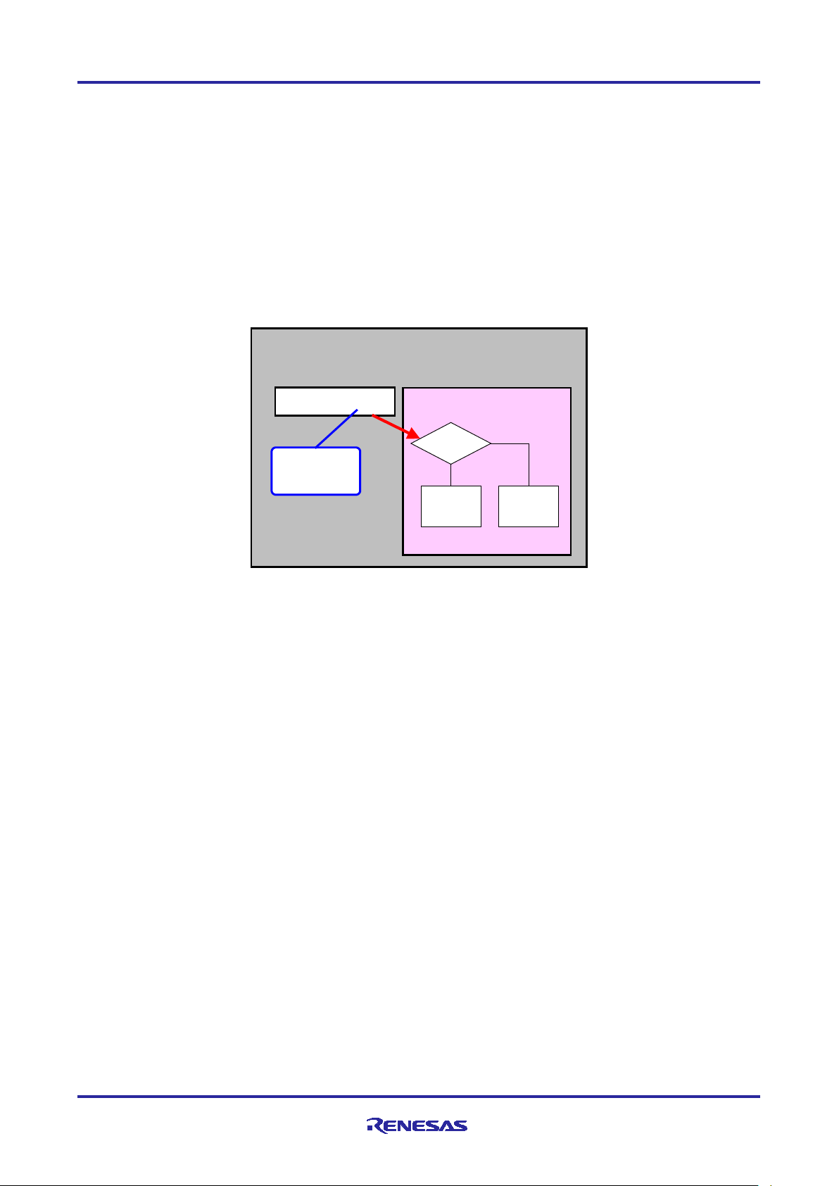
2.2.4 Program Branching by Product Name
The product name includes information designating the pin count and flash memory size.
It is possible to branch dynamically to different processing based on the product number (pin count). (For
example, the port numbers may differ even though the same functions are used.) This makes it possible for a
single program to support MCUs with different pin counts.
R20AN0615EJ0100 Rev.1.00 Page 6 of 14
Apr.13.21
Page 7

RL78/G23 Unique ID Read Driver
3. Related Application Notes
Application notes related to this application note are listed below. Consult them in conjunction with this
document.
Third-Party Program Protection Application Note (R20AN0616EJ)
R20AN0615EJ0100 Rev.1.00 Page 7 of 14
Apr.13.21
Page 8

RL78/G23 Unique ID Read Driver
File Name
Description
r_uniq_if.h
This is the header file of the unique ID read driver.
This file must be included in your project in order to use the unique ID read driver.
r_uniq_api.c
This is the source file of the unique ID read driver.
You must build this file in order to use the unique ID read driver.
4. Software Configuration
4.1 File Structure
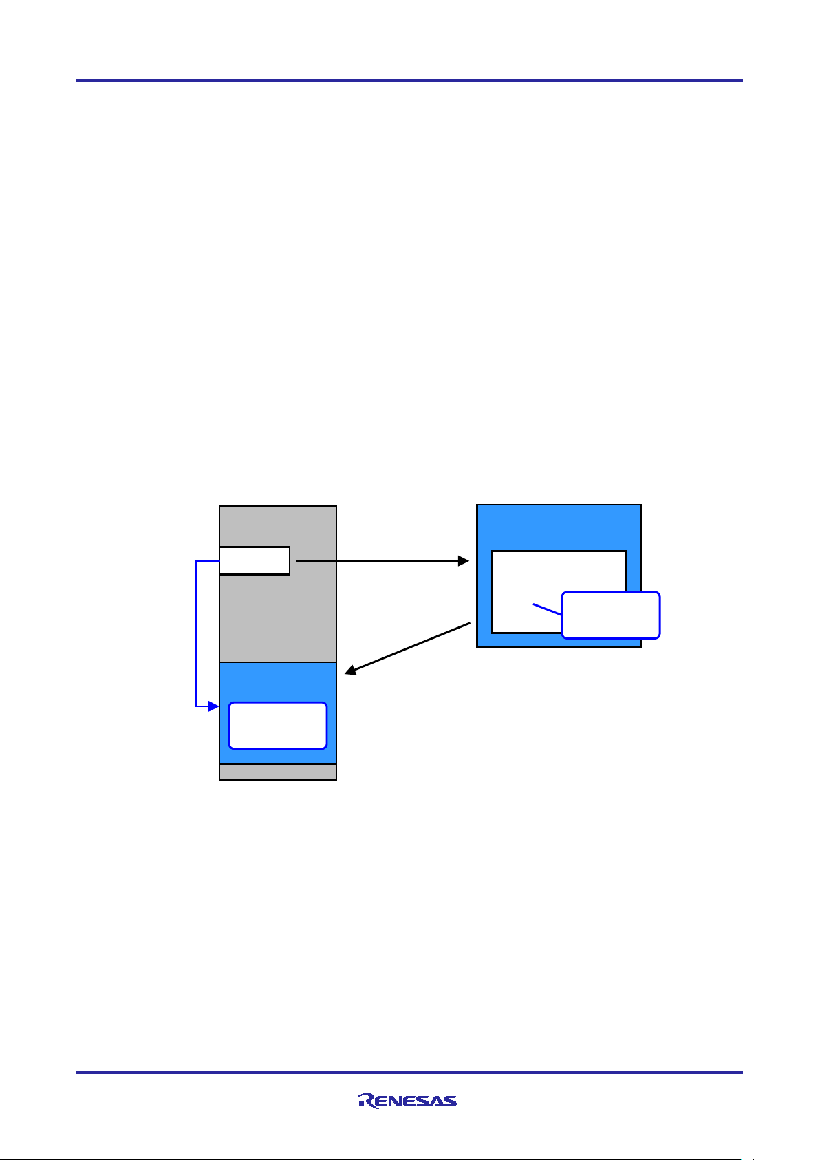
The unique ID read driver files are under libsrc in the file structure shown in Table 4.1 and Figure 4.1. Table
4.1 lists the role of each file. The relevant portion of the file structure is enclosed in the red box in Figure 4.1.
Table 4.1 Roles of Unique ID Read Driver Files
It contains macro, type, and prototype declarations that can be referenced by the user.
Figure 4.1 Driver File Structure in Distribution Package
R20AN0615EJ0100 Rev.1.00 Page 8 of 14
Apr.13.21
Page 9

RL78/G23 Unique ID Read Driver
Constant Name
Setting
Value
Description
File
UNIQ_CFG_PRV_UNIQID_SIZE
16
Byte count of unique ID
r_uniq_if.h
UNIQ_CFG_PRV_PDCT_SIZE
9
Byte count of product name ASCII
code
r_uniq_if.h
5. Data Configuration
5.1 Constants
Table 5.1 lists the constants used by the unique ID read driver. These constants are defined in the
r_uniq_if.h file.
Table 5.1 Constants Used by Unique ID Read Driver
5.2 Enumerated Types
5.2.1 End Status of Read Function
Table 5.2 End Status of Read Function
typedef enum
{
UID_SUCCESS = 0, /* Read successful */
UID_ERR_FAILURE /* Read failure */
} e_uniqid_err_t;
5.3 Structures
5.3.1 Unique ID Information
The unique ID is stored in this structure.
Table 5.3 Structure for Storing Unique ID
typedef struct
{
uint8_t uniq_id[UNIQ_CFG_PRV_UNIQID_SIZE];
} st_uniq_id_t;
5.3.2 Product Name ASCII Code Information
The product name ASCII code is stored in this structure.
Table 5.4 Structure for Product Name ASCII Code
typedef struct
{
uint8_t product_name[UNIQ_CFG_PRV_PDCT_SIZE];
} st_pdct_t;
R20AN0615EJ0100 Rev.1.00 Page 9 of 14
Apr.13.21
Page 10

RL78/G23 Unique ID Read Driver
Function Name
Description
Source File
R_UID_Read
Processing to read the unique ID
r_uniq_api.c
R_PDCT_Read
Processing to read the product name ASCII code
r_uniq_api.c
Format
e_uniqid_err_t R_UID_Read (st_uniq_id_t *pdest_addr)
Description
Performs processing to read the unique ID.
Parameters
pdest_addr
Pointer to the structure for storing the unique ID
Return Values
UID_SUCCESS
: Unique ID read normal end
Special Notes
Format
e_uniqid_err_t R_PDCT_Read (st_pdct_t *pdest_addr)
Description
Performs processing to read the product name ASCII code.
Parameters
pdest_addr
Pointer to the structure for storing the product name ASCII code
Return Values
UID_SUCCESS
: Unique ID read normal end
Special Notes
6. API Functions
Table 6.1 lists the functions of the unique ID read driver.
Table 6.1 Functions
6.1 R_UID_Read Function
Table 6.2 R_UID_Read Function Specifications
6.2 R_PDCT_Read Function
Table 6.3 R_PDCT_Read Function Specifications
R20AN0615EJ0100 Rev.1.00 Page 10 of 14
Apr.13.21
Page 11

RL78/G23 Unique ID Read Driver
No.
Device
Description
1
Development PC
The PC used for development.
2
Evaluation board
(RL78/G23 Fast Prototyping Board)
3
Host PC
the XMODEM/SUM transfer protocol
The development PC can also be used for this
4
USB cable (mini-B type)
Provides a USB connection between the evaluation
board and host PC.
RL78/G23 Fast Prototyping Board
E2Lite
RL78/G23
Micro USB
(FTDI)
USB cable
Host PC
(Serial communications
software)
Development
PC
Item
Description
Communication system
Asynchronous communication
Bit rate
115,200 bps
Data length
8 bits
Parity
None
Stop bit
1 bit
Flow control
None
7. Sample Project
This sample project is a software program that uses the unique ID read driver to read the unique ID and the
product name in ASCII code and then displays them in a terminal emulation application.
The program uses UART0 interfaced to a micro USB port.
A PC with a terminal emulation application running on it is necessary for output.
Table 7.1 Device Configuration
Serial communication software supporting
Figure 7.1 RL78/G23 Fast Prototyping Board Device Connection Diagram
Table 7.2 Communication Specifications
purpose.
R20AN0615EJ0100 Rev.1.00 Page 11 of 14
Apr.13.21
Page 12

RL78/G23 Unique ID Read Driver
Uniq ue ID
ASCI I code of p roduct name
unique ID[HEX]: 2e 18 17 30 33 30 38 31 30 33 fc b7 71 29 57 4b
product name : R7F100GLG
7.1 Processing Sequence of Sample Project
The following is an outline of the processing of the sample code.
(1) Start operation of UART0.
(2) Read unique ID.
(3) Read product name ASCII code.
(4) Display unique ID using printf() (send to terminal).
(5) Display product name ASCII code using printf() (send to terminal).
7.2 Settings and Execution
1. Connect the USB port of the PC to the micro USB port of the RL78/G23 Fast Prototyping Board as shown
in Figure 7.1, RL78/G23 Fast Prototyping Board Device Connection Diagram.
2. Launch the terminal emulation program (terminal software) on the PC. Then select the serial COM port
assigned to the USB serial converter board.
3. Make serial communication settings in the terminal software to match those of the sample application:
115,200 bps, 8 data bits, no parity, 1 stop bit, no flow control.
4. Build the sample application, download it to the RL78/G23 Fast Prototyping Board, and use the debugger
to run the application.
5. When the software runs, the unique ID and product name are output to the terminal, after which the
program terminates normally.
7.3 Note on Debugging
The flash memory area where the unique ID and product name ASCII code are stored cannot be read using
the debugger’s memory browser; FFH is displayed instead.
R20AN0615EJ0100 Rev.1.00 Page 12 of 14
Apr.13.21
Page 13

RL78/G23 Unique ID Read Driver
8. Reference Documents
RL78/G23 Group User’s Manual: Hardware (R01UH0896E)
RL78 Family User’s Manual: Software (R01US0015E)
Technical Update/Technical News
(The latest information can be downloaded from the Renesas Electronics website.)
R20AN0615EJ0100 Rev.1.00 Page 13 of 14
Apr.13.21
Page 14
RL78/G23 Unique ID Read Driver
Rev.
Date
Description
Page
Summary
1.00
Apr. 13, 2021
First edition issued
Revision History
R20AN0615EJ0100 Rev.1.00 Page 14 of 14
Apr.13.21
Page 15

General Precautions in the Handling of Microprocessing Unit and Microcontroller
Unit Products
The following usage notes are applicable to all Microprocessing unit and Microcontroller unit products from Renesas. For detailed usage notes on the
products covered by this document, refer to the relevant sections of the document as well as any technical updates that have been issued for the products.
1. Precaution against Electrostatic Discharge (ESD)
A strong electrical field, when exposed to a CMOS device, can cause destruction of the gate oxide and ultimately degrade the device operation. Steps
must be taken to stop the generation of static electricity as much as possible, and quickly dissipate it when it occurs. Environmental control must be
adequate. When it is dry, a humidifier should be used. This is recommended to avoid using insulators that can easily build up static electricity.
Semiconductor devices must be stored and transported in an anti-static container, static shielding bag or conductive material. All test and
measurement tools including work benches and floors must be grounded. The operator must also be grounded using a wrist strap. Semiconductor
devices must not be touched with bare hands. Similar precautions must be taken for printed circuit boards with mounted semiconductor devices.
2. Processing at power-on
The state of the product is undefined at the time when power is supplied. The states of internal circuits in the LSI are indeterminate and the states of
register settings and pins are undefined at the time when power is supplied. In a finished product where the reset signal is applied to the external reset
pin, the states of pins are not guaranteed from the time when power is supplied until the reset process is completed. In a similar way, the states of pins
in a product that is reset by an on-chip power-on reset function are not guaranteed from the time when power is supplied until the power reaches the
level at which resetting is specified.
3. Input of signal during power-off state
Do not input signals or an I/O pull-up power supply while the device is powered off. The current injection that results from input of such a signal or I/O
pull-up power supply may cause malfunction and the abnormal current that passes in the device at this time may cause degradation of internal
elements. Follow the guideline for input signal during power-off state as described in your product documentation.
4. Handling of unused pins
Handle unused pins in accordance with the directions given under handling of unused pins in the manual. The input pins of CMOS products are
generally in the high-impedance state. In operation with an unused pin in the open-circuit state, extra electromagnetic noise is induced in the vicinity of
the LSI, an associated shoot-through current flows internally, and malfunctions occur due to the false recognition of the pin state as an input signal
become possible.
5. Clock signals
After applying a reset, only release the reset line after the operating clock signal becomes stable. When switching the clock signal during program
execution, wait until the target clock signal is stabilized. When the clock signal is generated with an external resonator or from an external oscillator
during a reset, ensure that the reset line is only released after full stabilization of the clock signal. Additionally, when switching to a clock signal
produced with an external resonator or by an external oscillator while program execution is in progress, wait until the target clock signal is stable.
6. Voltage application waveform at input pin
Waveform distortion due to input noise or a reflected wave may cause malfunction. If the input of the CMOS device stays in the area between V
(Max.) and V
input level is fixed, and also in the transition period when the input level passes through the area between V
7. Prohibition of access to reserved addresses
Access to reserved addresses is prohibited. The reserved addresses are provided for possible future expansion of functions. Do not access these
addresses as the correct operation of the LSI is not guaranteed.
8. Differences between products
Before changing from one product to another, for example to a product with a different part number, confirm that the change will not lead to problems.
The characteristics of a microprocessing unit or microcontroller unit products in the same group but having a different part number might differ in terms
of internal memory capacity, layout pattern, and other factors, which can affect the ranges of electrical characteristics, such as characteristic values,
operating margins, immunity to noise, and amount of radiated noise. When changing to a product with a different part number, implement a system-
evaluation test for the given product.
(Min.) due to noise, for example, the device may malfunction. Take care to prevent chattering noise from entering the device when the
IH
(Max.) and VIH (Min.).
IL
IL
Page 16

Corporate Headquarters
Contact information
www.renesas.com
Trademarks
of their respective owners.
Notice
1. Descriptions of circuits, software and other related information in this document are provided only to illustrate the operation of semiconductor products
and application examples. You are fully responsible for the incorporation or any other use of the circuits, software, and information in the design of your
product or system. Renesas Electronics disclaims any and all liability for any losses and damages incurred by you or third parties arising from the use
of these circuits, software, or information.
2. Renesas Electronics hereby expressly disclaims any warranties against and liability for infringement or any other claims involving patents, copyrights,
or other intellectual property rights of third parties, by or arising from the use of Renesas Electronics products or technical information described in this
document, including but not limited to, the product data, drawings, charts, programs, algorithms, and application examples.
3. No license, express, implied or otherwise, is granted hereby under any patents, copyrights or other intellectual property rights of Renesas Electronics
or others.
4. You shall be responsible for determining what licenses are required from any third parties, and obtaining such licenses for the lawful import, export,
manufacture, sales, utilization, distribution or other disposal of any products incorporating Renesas Electronics products, if required.
5. You shall not alter, modify, copy, or reverse engineer any Renesas Electronics product, whether in whole or in part. Renesas Electronics disclaims any
and all liability for any losses or damages incurred by you or third parties arising from such alteration, modification, copying or reverse engineering.
6. Renesas Electronics products are classified according to the following two quality grades: “Standard” and “High Quality”. The intended applications for
each Renesas Electronics product depends on the product’s quality grade, as indicated below.
"Standard": Computers; office equipment; communications equipment; test and measurement equipment; audio and visual equipment; home
"High Quality": Transportation equipment (automobiles, trains, ships, etc.); traffic control (traffic lights); large-scale communication equipment; key
Unless expressly designated as a high reliability product or a product for harsh environments in a Renesas Electronics data sheet or other Renesas
Electronics document, Renesas Electronics products are not intended or authorized for use in products or systems that may pose a direct threat to
human life or bodily injury (artificial life support devices or systems; surgical implantations; etc.), or may cause serious property damage (space
system; undersea repeaters; nuclear power control systems; aircraft control systems; key plant systems; military equipment; etc.). Renesas Electronics
disclaims any and all liability for any damages or losses incurred by you or any third parties arising from the use of any Renesas Electronics product
that is inconsistent with any Renesas Electronics data sheet, user’s manual or other Renesas Electronics document.
7. No semiconductor product is absolutely secure. Notwithstanding any security measures or features that may be implemented in Renesas Electronics
hardware or software products, Renesas Electronics shall have absolutely no liability arising out of any vulnerability or security breach, including but
not limited to any unauthorized access to or use of a Renesas Electronics product or a system that uses a Renesas Electronics product. RENESAS
ELECTRONICS DOES NOT WARRANT OR GUARANTEE THAT RENESAS ELECTRONICS PRODUCTS, OR ANY SYSTEMS CREATED USING
RENESAS ELECTRONICS PRODUCTS WILL BE INVULNERABLE OR FREE FROM CORRUPTION, ATTACK, VIRUSES, INTERFERENCE,
HACKING, DATA LOSS OR THEFT, OR OTHER SECURITY INTRUSION (“Vulnerability Issues”). RENESAS ELECTRONICS DISCLAIMS ANY AND
ALL RESPONSIBILITY OR LIABILITY ARISING FROM OR RELATED TO ANY VULNERABILITY ISSUES. FURTHERMORE, TO THE EXTENT
PERMITTED BY APPLICABLE LAW, RENESAS ELECTRONICS DISCLAIMS ANY AND ALL WARRANTIES, EXPRESS OR IMPLIED, WITH
RESPECT TO THIS DOCUMENT AND ANY RELATED OR ACCOMPANYING SOFTWARE OR HARDWARE, INCLUDING BUT NOT LIMITED TO
THE IMPLIED WARRANTIES OF MERCHANTABILITY, OR FITNESS FOR A PARTICULAR PURPOSE.
8. When using Renesas Electronics products, refer to the latest product information (data sheets, user’s manuals, application notes, “General Notes for
Handling and Using Semiconductor Devices” in the reliability handbook, etc.), and ensure that usage conditions are within the ranges specified by
Renesas Electronics with respect to maximum ratings, operating power supply voltage range, heat dissipation characteristics, installation, etc. Renesas
Electronics disclaims any and all liability for any malfunctions, failure or accident arising out of the use of Renesas Electronics products outside of such
specified ranges.
9. Although Renesas Electronics endeavors to improve the quality and reliability of Renesas Electronics products, semiconductor products have specific
characteristics, such as the occurrence of failure at a certain rate and malfunctions under certain use conditions. Unless designated as a high reliability
product or a product for harsh environments in a Renesas Electronics data sheet or other Renesas Electronics document, Renesas Electronics
products are not subject to radiation resistance design. You are responsible for implementing safety measures to guard against the possibility of bodily
injury, injury or damage caused by fire, and/or danger to the public in the event of a failure or malfunction of Renesas Electronics products, such as
safety design for hardware and software, including but not limited to redundancy, fire control and malfunction prevention, appropriate treatment for
aging degradation or any other appropriate measures. Because the evaluation of microcomputer software alone is very difficult and impractical, you are
responsible for evaluating the safety of the final products or systems manufactured by you.
10. Please contact a Renesas Electronics sales office for details as to environmental matters such as the environmental compatibility of each Renesas
Electronics product. You are responsible for carefully and sufficiently investigating applicable laws and regulations that regulate the inclusion or use of
controlled substances, including without limitation, the EU RoHS Directive, and using Renesas Electronics products in compliance with all these
applicable laws and regulations. Renesas Electronics disclaims any and all liability for damages or losses occurring as a result of your noncompliance
with applicable laws and regulations.
11. Renesas Electronics products and technologies shall not be used for or incorporated into any products or systems whose manufacture, use, or sale is
prohibited under any applicable domestic or foreign laws or regulations. You shall comply with any applicable export control laws and regulations
promulgated and administered by the governments of any countries asserting jurisdiction over the parties or transactions.
12. It is the responsibility of the buyer or distributor of Renesas Electronics products, or any other party who distributes, disposes of, or otherwise sells or
transfers the product to a third party, to notify such third party in advance of the contents and conditions set forth in this document.
13. This document shall not be reprinted, reproduced or duplicated in any form, in whole or in part, without prior written consent of Renesas Electronics.
14. Please contact a Renesas Electronics sales office if you have any questions regarding the information contained in this document or Renesas
Electronics products.
(Note1) “Renesas Electronics” as used in this document means Renesas Electronics Corporation and also includes its directly or indirectly controlled
(Note2) “Renesas Electronics product(s)” means any product developed or manufactured by or for Renesas Electronics.
subsidiaries.
electronic appliances; machine tools; personal electronic equipment; industrial robots; etc.
financial terminal systems; safety control equipment; etc.
(Rev.5.0-1 October 2020)
TOYOSU FORESIA, 3-2-24 Toyosu,
Koto-ku, Tokyo 135-0061, Japan
Renesas and the Renesas logo are trademarks of Renesas Electronics
Corporation. All trademarks and registered trademarks are the property
For further information on a product, technology, the most up-to-date
version of a document, or your nearest sales office, please visit:
www.renesas.com/contact/
.
© 2021 Renesas Electronics Corporation. All rights reserved.
 Loading...