

Page 1

To our customers,
Old Company Name in Catalogs and Other Documents
On April 1st, 2010, NEC Electronics Corporation merged with Renesas Technology
Corporation, and Renesas Electronics Corporation took over all the business of both
companies. Therefore, although the old company name remains in this document, it is a valid
Renesas Electronics document. We appreciate your understanding.
Renesas Electronics website: http://www.renesas.com
April 1
Renesas Electronics Corporation
Issued by: Renesas Electronics Corporation (http://www.renesas.com)
st
, 2010
Send any inquiries to http://www.renesas.com/inquiry
.
Page 2

Notice
1. All information included in this document is current as of the date this document is issued. Such information, however, is
subject to change without any prior notice. Before purchasing or using any Renesas Electronics products listed herein, please
confirm the latest product information with a Renesas Electronics sales office. Also, please pay regular and careful attention to
additional and different information to be disclosed by Renesas Electronics such as that disclosed through our website.
2. Renesas Electronics does not assume any liability for infringement of patents, copyrights, or other intellectual property rights
of third parties by or arising from the use of Renesas Electronics products or technical information described in this document.
No license, express, implied or otherwise, is granted hereby under any patents, copyrights or other intellectual property rights
of Renesas Electronics or others.
3. You should not alter, modify, copy, or otherwise misappropriate any Renesas Electronics product, whether in whole or in part.
4. Descriptions of circuits, software and other related information in this document are provided only to illustrate the operation of
semiconductor products and application examples. You are fully responsible for the incorporation of these circuits, software,
and information in the design of your equipment. Renesas Electronics assumes no responsibility for any losses incurred by
you or third parties arising from the use of these circuits, software, or information.
5. When exporting the products or technology described in this document, you should comply with the applicable export control
laws and regulations and follow the procedures required by such laws and regulations. You should not use Renesas
Electronics products or the technology described in this document for any purpose relating to military applications or use by
the military, including but not limited to the development of weapons of mass destruction. Renesas Electronics products and
technology may not be used for or incorporated into any products or systems whose manufacture, use, or sale is prohibited
under any applicable domestic or foreign laws or regulations.
6. Renesas Electronics has used reasonable care in preparing the information included in this document, but Renesas Electronics
does not warrant that such informatio n is error free. Renesas Electronics assumes no liability whatsoever for any damages
incurred by you resulting from errors in or omissions from the information included herein.
7. Renesas Electronics products are classified according to the following three quality grades: “Standard”, “High Quality”, and
“Specific”. The recommended applications for each Renesas Electronics product depends on the product’s quality grade, as
indicated below. You must check the quality grade of each Renesas Electronics product before using it in a particular
application. You may not use any Renesas Electronics product for any application categorized as “Specific” without the prior
written consent of Renesas Electronics. Further, you may not use any Renesas Electronics product for any application for
which it is not intended without the prior written consent of Renesas Electronics. Renesas Electronics shall not be in any way
liable for any damages or losses incurred by you or third parties arising from the use of any Renesas Electronics product for an
application categorized as “Specific” or for which the product is not intended where you have failed to obtain the prior written
consent of Renesas Electronics. The quality grade of each Renesas Electronics product is “Standard” unless otherwise
expressly specified in a Ren esas E lectronics data sheets or dat a books, etc.
“Standard”: Computers; office equipment; communications equipment; test and measurement equipment; audio and visual
equipment; home electron ic appliances; machine tools; personal electronic equipment; and industrial robots.
“High Quality”: Transportation equipment (automobiles, trains, ships, etc.); traffic control systems; anti-disaster systems; anti-
crime systems; safety equipment; and medical equipment not specifically designed for life support.
“Specific”: Aircraft; aerospace equipment; submersible repeaters; nuclear reactor control systems; medical equipment or
systems for life support (e.g. artificial life support devices or systems), surgical implantations, or healthcare
intervention (e.g. excision, etc.), and any other appl i cations or purposes that pose a d irect threat to human life.
8. You should use the Renesas Electronics products described in this document within the range specified by Renesas Electronics,
especially with respect to the maximum rating, operating supply voltage range, movement power voltage range, heat radiation
characteristics, installation and other product characteristics. Renesas Electronics shall have no liability for malfunctions or
damages arising out of the use of Renesas Electronics products beyond such specified ranges.
9. Although Renesas Electronics endeavors to improve the quality and reliability of its products, semiconductor products have
specific characteristics such as t he occu rrence o f failure at a certai n rate an d malfunct io ns under cert ain u se con dition s. Further,
Renesas Electronics prod ucts are not subject to radiation resistance design. Please be sure to implement safety measures to
guard them against the possibility of physical injury, and injury or damage caused by fire in the event of the failure of a
Renesas Electronics product, such as safety design for hardware and software including but not limited to redundancy, fire
control and malfunction prevention, appropriate treatment for aging degradation or any other appropriate measures. Because
the evaluation of microcomputer software alone is very difficult, please evaluate the safety of the final products or system
manufactured by you.
10. Please contact a Renesas Electronics sales office for details as to environmental matters such as the environmental
compatibility of each Renesas Electronics product. Please use Renesas Electronics products in compliance with all applicable
laws and regulations that regulate the inclusion or use of controlled substances, including without limitation, the EU RoHS
Directive. Renesas Electronics assumes no liability for damages or losses occurring as a result of your noncompliance with
applicable laws and regulations.
11. This document may not be reproduced or duplicated, in any form, in whole or in part, without prior written consent of Renesas
Electronics.
12. Please contact a Renesas Electronics sales office if you have any questions regarding the information contained in this
document or Renesas Electronics products, or if you have any other inquiries.
(Note 1) “Renesas Electronics” as used in this document means Renesas Electronics Corporation an d also includes its majority-
owned subsidiaries.
(Note 2) “Renesas Electronics product(s)” means any product developed or manufactured by or for Renesas Electronics.
Page 3

User’s Manual
Renesas Embedded
Application Programming Interface
Reference manual
Rev.1.01 2007.02
Page 4

REVISION HISTORY
Rev.
1.00 06.04.07
1.01 ・ Additions and corrections made for support of libraries for the H8/36094, H8/36077,
H8/36109, and R8C/24 and 25
・ Unnecessary periods in Chapter 1, “Instruction,” deleted
・ Port P73 of H8 deleted
・ Channels A–D written in CreateInputCapture corrected to input captures A–D
・ Error in writing “seroal” corrected to “serial”
・ Erroneous description of RAPI_70_STATES corrected
・ Error in writing of timer channel names corrected
・ Error in writing of input capture mode corrected
・ Error in writing of output compare mode corrected
・ Erroneous description of RAPI_OVERFLOW_BIT15 corrected
・ Support for R8C UART1 clock synchronous mode
・ RAPI_COUNT_CLEAR added to first arguments for the R8C and H8/300H in
__CreateInputCapture and __CreateOutputCompare
・ “External signal” deleted from the timer RD count source for the R8C in
__CreateInputCapture and __CreateOutputCompare
・ Following statements added to the item for timer RD in __SetTimerRegister and
__GetTimerRegister
・ [15]: Timer RD output master enable register 1
・ [16]: Timer RD output master enable register 2
・ [17]: Timer RD output control register
・ Explanation for clearing H8/300H module added to the description of __Create...,
__Open..., and __BasicOpen...
・ Explanation for setting H8/300H module for standby added to the description of
__Destroy..., __Close..., and BasicClose...
・ Return value in __PollingSerialReceiving changed from Boolean to unsigned int, and
explanation of return value and example program changed
・ Return value in __PollingSerialSending changed from Boolean to unsigned int, and
explanation of return value and example program changed
・ Remarks regarding use of port B on H8/300H added to __ReadIOPort and
__ReadIOPortRegister
Summary
Date
07.02.16
Rev.1.01 2007.02.16
RJJ10J1643-0101
2
Page 5

・ Description of third argument in __CreateInputCapture corrected
・ Wording “specified” unified to “specified”
・ RAPI_BOTH deleted from the description of timer B1 count edges of H8/300H in
__CreateEventCounter
・ RAPI_FTIOA and RAPI_FTIOB added to __CreatePulsePeriodMeasurementMode and
__CreatePulseWidthMeasurementMode
・ All occurrences of the word “Tiny” deleted
・ Description of second argument added to __GetPulsePeriodMeasurementMode,
__GetPulseWidthMeasurementMode, and __GetEventCounter
・ Description regarding timer V trigger of H8 in __CreateTimer, __CreateEventCounter,
and __CreatePulseWidthMeasurementMode corrected
・ Explanation of H8 interrupt settings and interrupt control register settings in
__SetSerialInterrupt corrected
・ Remarks on timer V of H8/300H in __EnableTimerRegister added
・ Specification of timer RA input pins of R8C in __CreatePulsePeriodMeasurementMode
and __CreatePulseWidthMeasurementMode as well as RAPI_TIOSEL_P1_7 and
RAPI_TIOSEL_P1_5 added
・ File name in program example corrected
・ Item “Reference” in __BasicSetSerialFormat deleted
・ __BasicSetSerialFormat added to “Reference” in __SetSerialFormat and
__SetSerialInterrupt
・ Error in writing of __CreateInput Capture and __CreateOutputCapture corrected
・ Explanation added to Section 2.1, “Overview”
・ Causes of clearing of timer W and timer RC counters in __CreateInputCapture deleted
・ RAPI_COMPARE_MATCH_A_STOP and RAPI_STOP added to the item for the R8C in
__CreateOutputCompare
・ Changed to RAPI_INT_LV_0 and RAPI_INT_LV_1 for H8/300H in __SetSerialInterrupt
・ Description relating to clock in __CreateTimer corrected
・ RAPI_TRC_FILTER and RAPI_TRD_FILTER added to filter specification for H8 in
__CreatePulsePeriodMeasurementMode and __CreatePulseWidthMeasurementMode
・ RAPI_TIMER_RD2 and RAPI_TIMER_RD3 added to timer RD of H8/36109
・ Description relating to timer V trigger input for H8/300H in __CreateTimer deleted
・ Description of pulse output function added to the item for R8C in
__CreateEventCounter
Description of timer RE usage added to items data3 and data5 for R8C in
・
__CreateOutputCompare
・ Filter function of timer RC and timer RD in __CreatePulsePeriodMeasurementMode,
__CreatePulseWidthMeasurementMode, and __CreateInputCapture corrected
・ Description that multiple defined values can be set for data1 in __EnableInterrupt
added
・ Description that RAPI_WITHOUT_SAMPLE_HOLD is specifiable in delay trigger
modes 0 and 1 of M16C in __CreateADC corrected
・ Description that RAPI_FOCOF is specifiable in repeat mode of R8C in __CreateADC
corrected
Rev.1.01 2007.02.16
RJJ10J1643-0101
3
Page 6

・ RAPI_AN30, RAPI_AN31, RAPI_AN32, and RAPI_P9_GROUP added to the item for
data1 of M16C in __CreateADC
・ RAPI_AN30, RAPI_AN31, RAPI_AN32, and RAPI_P9_GROUP added to the item for
data1 of M16C in __EnableADC
・ Error in writing of H8/300H interrupt set values in __CreateOutputCompare corrected
・ Error in writing of timer RD and timer RD symbol name corrected
・ Description of gate function of M16C in __CreateEventCounter deleted
・ Description of H8/300H noise rejection function in __BasicSetSerialFormat added
・ Description of timer W input pins of H8/300H in
__CreatePulsePeriodMeasurementMode and __CreatePulseWidthMeasurementMode
deleted
Rev.1.01 2007.02.16
RJJ10J1643-0101
4
Page 7

Table of Contents
Table of Contents ................................................................5
1. Introduction................................................................... 8
2. Driver ....................................................................... 9
2.1 Overview.................................................................. 9
2.2 Driver Features ............................................................ 10
2.3 Serial Interface Driver....................................................... 11
2.4 Timer Driver .............................................................. 12
2.4.1 Timer Mode ........................................................... 12
2.4.2 Event Counter Mode .................................................... 12
2.4.3 Pulse Width Modulation Mode (PWM Mode)................................. 12
2.4.4 Pulse Period Measurement Mode .......................................... 12
2.4.5 Pulse Width Measurement Mode........................................... 12
2.4.6 Input Capture Mode..................................................... 12
2.4.7 Output Compare Mode .................................................. 13
2.5 I/O Port Driver ............................................................ 14
2.6 External Interrupt Driver..................................................... 15
2.7 A/D Converter Driver ....................................................... 16
3. Standard Types ............................................................... 18
4. Library Reference............................................................. 19
4.1 API List by Peripheral Facility ................................................ 19
4.2 Description of Each API ..................................................... 21
4.2.1 Serial I/O ............................................................. 22
__BasicOpenSerialDriver................................................... 22
__BasicCloseSerialDriver................................................... 23
__BasicSetSerialFormat .................................................... 24
__BasicStartSerialReceiving................................................. 29
__BasicStartSerialSending .................................................. 30
__BasicReceivingStatusRead ................................................ 31
__BasicSendingStatusRead.................................................. 33
__BasicStopSerialReceiving................................................. 34
__BasicStopSerialSending .................................................. 35
__OpenSerialDriver ....................................................... 36
__CloseSerialDriver ....................................................... 37
__ConfigSerialDriverNotify................................................. 38
__SetSerialFormat......................................................... 41
__SetSerialInterrupt ....................................................... 42
__StartSerialReceiving ..................................................... 45
__StartSerialSending....................................................... 47
__StopSerialReceiving ..................................................... 49
__StopSerialSending....................................................... 50
__PollingSerialReceiving ................................................... 51
__PollingSerialSending..................................................... 52
4.2.2 Timer ................................................................54
Rev.1.01 2007.02.16
RJJ10J1643-0101
5
Page 8

__CreateTimer ........................................................... 54
__EnableTimer ........................................................... 60
__DestroyTimer .......................................................... 62
__CreateEventCounter ..................................................... 64
__EnableEventCounter..................................................... 69
__DestroyEventCounter .................................................... 71
__GetEventCounter........................................................ 73
__CreatePulseWidthModulationMode ......................................... 75
__EnablePulseWidthModulationMode......................................... 80
__DestroyPulseWidthModulationMode ........................................ 82
__CreatePulsePeriodMeasurementMode ....................................... 83
__EnablePulsePeriodMeasurementMode ....................................... 88
__DestroyPulsePeriodMeasurementMode ...................................... 90
__GetPulsePeriodMeasurementMode.......................................... 92
__CreatePulseWidthMeasurementMode........................................ 94
__EnablePulseWidthMeasurementMode ....................................... 99
__DestroyPulseWidthMeasurementMode ..................................... 101
__GetPulseWidthMeasurementMode ......................................... 103
__CreateInputCapture..................................................... 105
__EnableInputCapture .................................................... 115
__DestroyInputCapture.................................................... 117
__GetInputCapture ....................................................... 119
__CreateOutputCompare .................................................. 121
__EnableOutputCompare .................................................. 133
__DestroyOutputCompare ................................................. 135
__SetTimerRegister ...................................................... 137
__EnableTimerRegister.................................................... 143
__ClearTimerRegister..................................................... 145
__GetTimerRegister ...................................................... 147
4.2.3 I/O Port ............................................................. 153
__SetIOPort ............................................................ 153
__ReadIOPort ........................................................... 158
__WriteIOPort........................................................... 162
__SetIOPortRegister...................................................... 166
__ReadIOPortRegister .................................................... 168
__WriteIOPortRegister.................................................... 170
4.2.4 External interrupt...................................................... 172
__SetInterrupt ........................................................... 172
__EnableInterrupt ........................................................ 176
__GetInterruptFlag ....................................................... 178
__ClearInterruptFlag...................................................... 180
4.2.5 A/D converter......................................................... 182
__CreateADC ........................................................... 182
__EnableADC........................................................... 191
__DestroyADC .......................................................... 196
Rev.1.01 2007.02.16
RJJ10J1643-0101
6
Page 9

__GetADC ............................................................. 197
__GetADCAll........................................................... 198
__GetADCStatus......................................................... 199
__ClearADCStatus ....................................................... 200
Rev.1.01 2007.02.16
RJJ10J1643-0101
7
Page 10

1. Introduction
The Renesas Embedded Application Programming Interface (API) is a unified API for
the microcomputers made by Renesas Technology Corporation.
Rev.1.01 2007.02.16
RJJ10J1643-0101
8
Page 11

2. Driver
2.1 Overview
The library described herein provides a peripheral facility control program (peripheral
driver) for microcomputers. Use of the Renesas API permits the peripheral driver to be
built into a user program.
Configuration of Renesas APIs is shown below.
File name Description
rapi_
xxx_yyy
(
xxx
= family name,
rapi_ad_
xxx
= family name,
(
rapi_io_port_
xxx
= family name,
(
rapi_sif_
xxx
= family name,
(
rapi_timer_
xxx
= family name,
(
Interrupt_
(
xxx
= family name,
rapi_io_
xxx
= family name,
(
.lib
xxx_yyy
xxx_yyy
xxx_yyy
xxx_yyy
xxx_yyy
xxx_yyy
.h
.h
.h
yyy
= series name)
yyy
= series name)
.h
yyy
= series name)
yyy
= series name)
.h
yyy
= series name)
.h
yyy
= series name)
yyy
= series name)
This is the Renesas API library file. To use
Renesas APIs, specify this file as input file
for the linker.
This is the header file for A/D converter
driver APIs. To use A/D converter driver
APIs, be sure to include this file.
This is the header file for I/O port driver
APIs. To use I/O port driver APIs, be sure
to include this file.
This is the header file for serial I/F driver
APIs. To use serial I/F driver APIs, be sure
to include this file.
This is the header file for timer driver
APIs. To use timer driver APIs, be sure to
include this file.
This is the interrupt function source file for
Renesas APIs. To use Renesas APIs that
use interrupts, add this file to the user
program.
This is the CPU control register definition
header file for Renesas APIs.
Rev.1.01 2007.02.16
RJJ10J1643-0101
9
Page 12

2.2 Driver Features
The library described herein has the following features available as a peripheral driver.
(1) Serial I/O control feature
It comprises a serial interface driver, which sets or clears the conditions of serial
communication, as well as controls and manages the transmission/reception of
communication data.
(2) Timer control feature
It comprises a timer driver, which sets or clears the operating conditions of timers,
as well as controls the timer operation.
(3) I/O port control feature
It comprises an I/O port driver, which sets or clears the usage conditions of I/O ports, as
well as control data read/write operation.
(4) External interrupt control feature
It comprises an external interrupt driver, which sets or clears the usage conditions of
external interrupts, as well as controls interrupt operation.
(5) A/D converter control feature
It comprises an A/D converter driver, which sets or clears the usage conditions of A/D
converters, as well as controls A/D converter operation.
Rev.1.01 2007.02.16
RJJ10J1643-0101
10
Page 13

2.3 Serial Interface Driver
The serial interface driver sets serial communication, clears settings, transmit/receives
data, and controls the status of serial communication.
There are two kinds of serial interface driver: a single-data transmission/reception API
and a multi-data transmission/reception API.
Rev.1.01 2007.02.16
RJJ10J1643-0101
11
Page 14

2.4 Timer Driver
The timer driver sets the timer, clears timer settings, controls timer operation, and
acquires a counter value with respect to the following modes:
• Timer mode
• Event counter mode
• Pulse width modulation mode (PWM mode)
• Pulse period measurement mode
• Pulse width measurement mode
• Input capture mode
• Output compare mode
2.4.1 Timer Mode
In this mode, the timer counts the internally generated count source. When an
underflow or an overflow interrupt occurs, it calls a preset callback function.
2.4.2 Event Counter Mode
In this mode, the timer counts the external signal fed in from an input pin or an
overflow or underflow from other timer. When an underflow or an overflow interrupt
occurs, it calls a preset callback function.
2.4.3 Pulse Width Modulation Mode (PWM Mode)
In this mode, the timer outputs pulses in a given width successively. When an
underflow or an overflow interrupt occurs, it calls a preset callback function.
2.4.4 Pulse Period Measurement Mode
In this mode, the timer measures the pulse period of an external signal fed in from an
input pin. When an underflow or an overflow interrupt occurs, it calls a preset callback
function.
2.4.5 Pulse Width Measurement Mode
In this mode, the timer measures the pulse width of an external signal fed in from an
input pin. When an underflow or an overflow interrupt occurs, it calls a preset callback
function.
2.4.6 Input Capture Mode
In this mode, the timer latches the timer value upon an active signal edge or clock
pulse at an input pin, thereby generating an interrupt request. When an input capture
interrupt or an underflow or an overflow interrupt occurs, it calls a preset callback
function.
Rev.1.01 2007.02.16
RJJ10J1643-0101
12
Page 15

2.4.7 Output Compare Mode
In this mode, the timer generates an interrupt request when the timer counter and a
comparison value match. When a compare match interrupt or an underflow or an
overflow interrupt occurs, it calls a preset callback function.
Rev.1.01 2007.02.16
RJJ10J1643-0101
13
Page 16

2.5 I/O Port Driver
The I/O port driver sets the I/O port for input or output, writes data to the I/O port, and
reads data from the I/O port.
Rev.1.01 2007.02.16
RJJ10J1643-0101
14
Page 17

2.6 External Interrupt Driver
The external interrupt driver sets external interrupts, controls external interrupts,
acquires the status of external interrupt flags, and clears external interrupt flags.
Rev.1.01 2007.02.16
RJJ10J1643-0101
15
Page 18
2.7 A/D Converter Driver
_
_
_
_
_
The A/D converter driver sets the A/D converter, controls the A/D converter, clears
settings of the A/D converter, acquires the A/D converter value, acquires the status of the
A/D converter, and clears the status of the A/D converter.
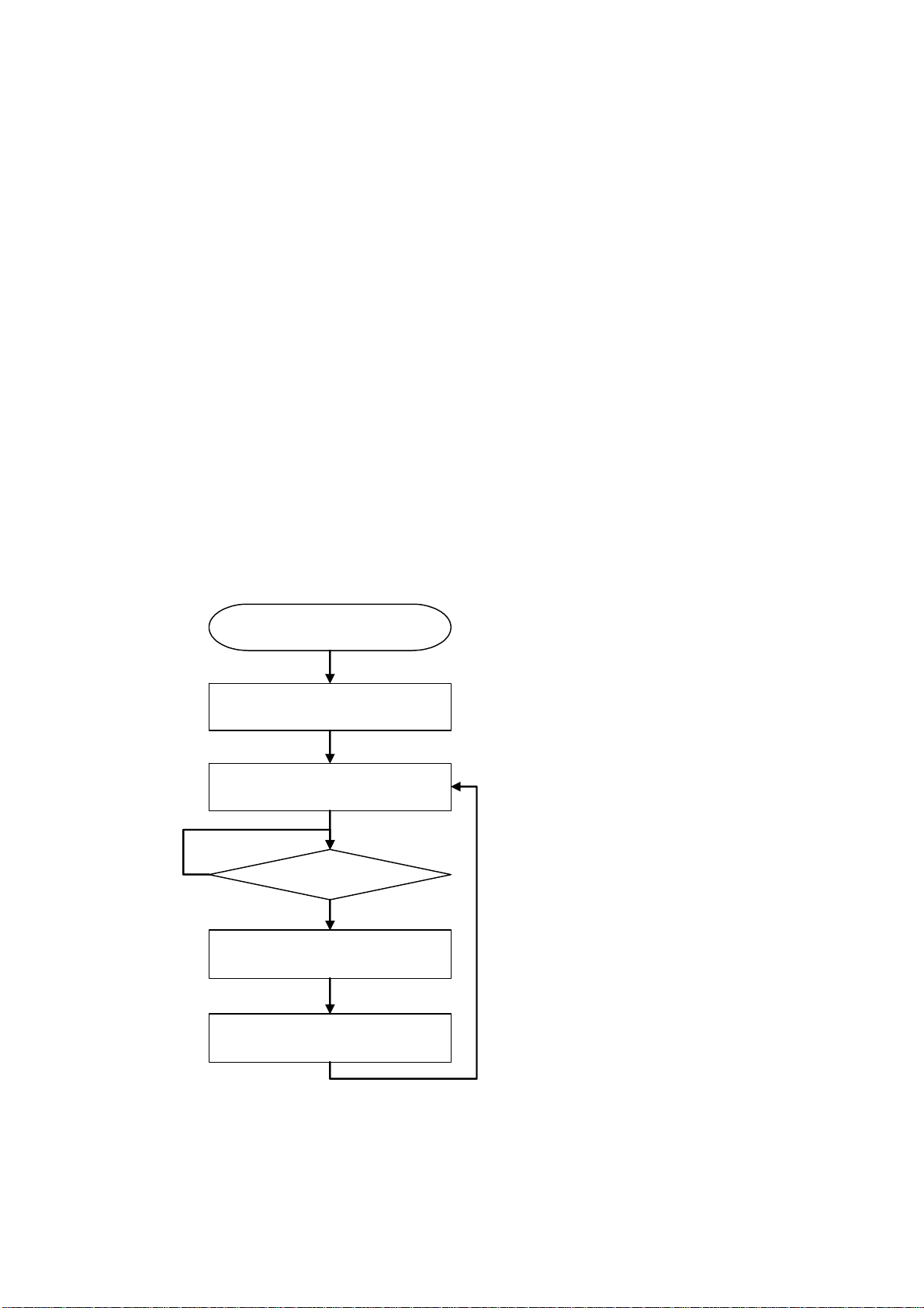
[A/D converter driver usage example (single-shot mode)]
Here, a program example is shown for the A/D converter operating in single-shot mode
under the conditions given below.
CPU : R8C
Operating clock : fAD divided by 2
Resolution : 10 bits
Analog input pin : AN0 pin
A/D conversion start condition : Software trigger
Sample-and-hold : Enabled
A program flow and a program example are shown below.
(Program flow)
main()
Set the A/D converter in
single-shot mode
Start A/D conversion
No
A/D interrupt?
Yes
Read out the A/D conversion value
Clear the A/D interrupt flag
_CreateADC()
_EnableADC()
_GetADCStatus()
_GetADC()
_ClearADCStatus()
Rev.1.01 2007.02.16
16
RJJ10J1643-0101
Page 19

__
Program example
#include "rapi_ad_r8c_13.h"
void main( void )
{
unsigned int status, data;
/* Set up A/D converter as one short mode */
RAPI_WITH_SAMPLE_HOLD|
RAPI_AD_OFF|RAPI_10BIT, 1, 0, 0 );
while( 1 ){
/* Disable A/D converter */
__EnableADC( RAPI_AN0| RAPI_AD_ON, 1 );
/* Check a flag bit of A/D converter interrupt */
do{
__GetADCStatus( &status );
} while( (*status & 0x0001) == 0 )
/* Get A/D convertered datas of A/D register */
__GetADC( &data );
/* Clear status of A/D convertered */
__ClearADCStatus( 0 );
}
}
CreateADC( RAPI_ONE_SHOT|RAPI_AN0|RAPI_FAD2|
Rev.1.01 2007.02.16
RJJ10J1643-0101
17
Page 20

3. Standard Types
This section describes the standard types defined in the library. For details about the
set values, refer to the description of each API.
Standard type Description
Boolean
Voi dF unc No ti fy
The Boolean type represents the enum-type data that indicates
whether successful (RAPI_TRUE (= 1)) or failed (RAPI_FALSE (=
0)).
The VoidFuncNotify type represents the type of the notification
function to be registered.
Rev.1.01 2007.02.16
RJJ10J1643-0101
18
Page 21
4. Library Reference
4.1 API List by Peripheral Facility
The table below lists the Renesas Embedded APIs classified by peripheral facility.
NO Facility
classification
Single-data
1 __BasicOpenSerialDriver
serial I/O
2 __BasicCloseSerialDriver
3 __BasicSetSerialFormat
4 __BasicStartSerialReceiving
5 __BasicStartSerialSending
6 __BasicReceivingStatusRead
7 __BasicSendingStatusRead
8 __BasicStopSerialReceiving
9
Multi-data
10 __OpenSerialDriver
serial I/O
11 __CloseSerialDriver
12 __ConfigSerialDriverNotify
13 __SetSerialFormat
14 __SetSerialInterrupt
15 __StartSerialReceiving
16 __StartSerialSending
17 __StopSerialReceiving
18 __StopSerialSending
19 __PollingSerialReceiving
20
Timer
21 __CreateTimer
22 __EnableTimer
23 __DestroyTimer
24 __CreateEventCounter
25 __EnableEventCounter
26 __DestroyEventCounter
27 __GetEventCounter
28 __CreatePulseWidthModulationMode
29 __EnablePulseWidthModulationMode
30 __DestroyPulseWidthModulationMode
31 __CreatePulsePeriodMeasurementMode
32 __EnablePulsePeriodMeasurementMode
33 __DestroyPulsePeriodMeasurementMode
34
__BasicStopSerialSending
__PollingSerialSending
__GetPulsePeriodMeasurementMode
API API operation
Opens serial port
Closes serial port
Sets serial communication
Receives 1 data
Transmits 1 data
Reads receive status
Reads transmit status
Stops reception
Stops transmission
Opens serial port
Closes serial port
Registers notification function
Sets serial communication
Sets transmit/receive interrupt
Starts reception
Starts transmission
Stops reception
Stops transmission
Receives by polling
Transmits by polling
Sets timer mode
Controls timer mode operation
Clears timer mode setting
Sets event counter mode
Controls operation of event counter
mode
Clears setting of event counter
mode
Gets event counter mode counter
value
Sets pulse width modulation mode
Controls operation of pulse width
modulation mode
Clears setting of pulse width
modulation mode
Sets pulse period measurement
mode
Controls operation of pulse period
measurement mode
Clears setting of pulse width
measurement mode
Acquires measured value of pulse
period measurement mode
Rev.1.01 2007.02.16
RJJ10J1643-0101
19
Page 22
35 __CreatePulseWidthMeasurementMode
36 __EnablePulseWidthMeasurementMode
Timer
37 __DestroyPulseWidthMeasurementMode
38 __GetPulseWidthMeasurementMode
39 __CreateInputCapture
40 __EnableInputCapture
41 __DestroyInputCapture
42 __GetInputCapture
43 __CreateOutputCompare
44 __EnableOutputCompare
45 __DestroyOutputCompare
46 __SetTimerRegister
47 __EnableTimerRegister
48 __ClearTimerRegister
49
I/O port
50 __SetIOPort
51 __ReadIOPort
52 __WriteIOPort
53 __SetIOPortRegister
54 __ReadIOPortRegister
55
External
56 __SetInterrupt
interrupt
57 __EnableInterrupt
58 __GetInterruptFlag
59
A/D converter
60 __CreateADC
61 __EnableADC
62 __DestroyADC
63 __GetADC
64 __GetADCAll
65 __GetADCStatus
66
__GetTimerRegister
__WriteIOPortRegister
__ClearInterruptFlag
__ClearADCStatus Clears status of A/D converter
Sets pulse width measurement
mode
Controls operation of pulse width
measurement mode
Clears setting of pulse width
measurement mode
Acquires measured value of pulse
width measurement mode
Sets input capture mode
Controls operation of input capture
mode
Clears setting of input capture mode
Acquires counter value of input
capture mode
Sets output compare mode
Controls operation of output
compare mode
Clears setting of output compare
mode
Sets timer register
Controls operation of timer register
Clears timer register
Gets timer register value
Sets I/O port
Reads from I/O port
Writes to I/O port
Sets I/O port register
Reads from I/O port register
Writes to I/O port register
Sets external interrupt
Controls external interrupt
Gets flag status of external interrupt
Clears flag of external interrupt
Sets A/D converter
Controls operation of A/D converter
Discards settings of A/D converter
Gets A/D conversion value (register
specified)
Gets A/D conversion value (all
registers)
Gets status of A/D converter
Rev.1.01 2007.02.16
RJJ10J1643-0101
20
Page 23

4.2 Description of Each API
This section describes each API and explains how to use them, showing a program
example for each.
The description of each API is divided into the following items.
• Synopsis
• Description
• Return value
• Functionality
• Reference
• Remark
• Program example
: Outlines the content of processing performed by the function. It
also shows the syntax of the function, followed by a brief
explanation of arguments.
: Describes the function and how to use it in detail.
: Explains the returned value of the function.
: Indicates the functional classification of the function.
: Indicates the related functions.
: Describes the precautions to be taken when using the API.
: Presents a program showing how to use the function.
Rev.1.01 2007.02.16
RJJ10J1643-0101
21
Page 24
4.2.1 Serial I/O
__BasicOpenSerialDriver
Synopsis
Description
For data, the following values can be set.
(M16C)
(R8C)
(H8/300H)
Return value
Functionality
Reference
Remark
<Open a serial port>
Boolean __BasicOpenSerialDriver(unsigned long data)
data Setup data
Opens and initializes a specified serial port.
RAPI_COM1 UART0 RAPI_COM2 UART1
RAPI_COM3 UART2 RAPI_COM4 SI/O3
RAPI_COM5 SI/O4
RAPI_COM1 UART0 RAPI_COM2 UART1
RAPI_COM1 SCI3 channel 1 RAPI_COM2 SCI3 channel 2
RAPI_COM3 SCI3 channel 3
If the serial port specification is incorrect, RAPI_FALSE is returned; otherwise,
RAPI_TRUE is returned.
Serial I/O
__BasicCloseSerialDriver
The specifiable serial ports differ with each CPU used.
•
If an undefined value is specified in the argument, operation of the API cannot be
•
guaranteed.
When used for the H8/300H, this API opens and initializes a specified serial port
•
when freeing it from module standby state.
Program example
#include ”rapi_sif_r8c_13.h”
void func( void )
{
/* Open serial driver */
return __BasicOpenSerialDriver( RAPI_COM1 );
}
Rev.1.01 2007.02.16
RJJ10J1643-0101
22
Page 25
__BasicCloseSerialDriver
Synopsis
Description
(R8C)
(H8/300H)
<Close a serial port>
Boolean __BasicCloseSerialDriver(unsigned long data)
data Setup data
Closes a specified serial port. For data, the following values can be set.
(M16C)
RAPI_COM1 UART0 RAPI_COM2 UART1
RAPI_COM3 UART2 RAPI_COM4 SI/O3
RAPI_COM5 SI/O4
RAPI_COM1 UART0 RAPI_COM2 UART1
RAPI_COM1 SCI3 channel 1 RAPI_COM2 SCI3 channel 2
RAPI_COM3 SCI3 channel 3
Return value
Functionality
Reference
If the serial port specification is incorrect, RAPI_FALSE is returned; otherwise,
RAPI_TRUE is returned.
Serial I/O
__BasicOpenSerialDriver
The specifiable serial ports differ with each CPU used.
Remark
•
If an undefined value is specified in the argument, operation of the API cannot be
•
guaranteed.
When used for the H8/300H, this API places a specified serial port into module
•
standby state after closing it.
Program example
#include ”rapi_sif_r8c_13.h”
void func( void )
{
/* Close serial driver */
return Rapi_BasicCloseSerialDriver( RAPI_COM1 );
}
Rev.1.01 2007.02.16
RJJ10J1643-0101
23
Page 26

__BasicSetSerialFormat
Synopsis
Description
<Set serial communication>
Boolean __BasicSetSerialFormat(unsigned long data1, unsigned char data2)
data1 Setup data 1
data2 Setup data 2
Sets serial communication according to specified parameters.
[data1]
For data1, the following values can be set. To set multiple definition values at the same
time, use the symbol “|” to separate each specified value.
(M16C)
RAPI_COM1 UART0 RAPI_COM2 UART1
RAPI_COM3 UART2 RAPI_COM4 SI/O3
RAPI_COM5 SI/O4
For serial communication mode, the following values can be set.
(M16C) (UART0, UART1, UART2)
RAPI_SM_SYNC
RAPI_SM_ASYNC
(M16C)(SI/O3, SI/O4)
RAPI_SIO_SM_SYNC
For the data length format of clock asynchronous serial communication, the following
values can be set.
If the API is used in clock synchronous serial communication mode, do not set these
values.
(M16C) (UART0, UART1, UART2)
RAPI_BIT_7 Transfer data length 7 bits RAPI_BIT_8 Transfer data length 8 bits
RAPI_BIT_9 Transfer data length 9 bits
For the clock source of serial communication, the following values can be set.
(M16C) (UART0, UART1, UART2)
RAPI_CKDIR_INT Internal clock is used as the clock source of serial communication.
RAPI_CKDIR_EXT External clock is used as the clock source of serial communication.
(M16C) (SI/O3, SI/O4)
RAPI_SIO_CKDIR_INT Internal clock is used as the clock source of serial communication.
RAPI_SIO_CKDIR_EXT External clock is used as the clock source of serial communication.
For the stop bit length of clock asynchronous serial communication, the following
values can be set.
If the API is used in clock synchronous serial communication mode, do not set these
values.
(M16C) (UART0, UART1, UART2)
RAPI_STPB_1 1 stop bit RAPI_STPB_2 2 stop bits
For the parity bit of clock asynchronous serial communication, the following values can
be set.
Clock synchronous serial communication mode
Clock asynchronous serial communication mode
Clock synchronous serial communication mode
Rev.1.01 2007.02.16
RJJ10J1643-0101
24
Page 27
If the API is used in clock synchronous serial communication mode, do not set these
values.
(M16C) (UART0, UART1, UART2)
RAPI_PARITY_NON No parity bit RAPI_PARITY_EVEN Even parity bit
RAPI_PARITY_ODD Odd parity bit
For the clock polarity of serial communication, the following values can be set.
If the API is used in clock asynchronous serial communication mode, do not set these
values.
(M16C) (UART0, UART1, UART2)
RAPI_DPOL_NON Polarity not inverted RAPI_DPOL_INV Polarity inverted
(M16C) (SI/O3, SI/O4)
RAPI_SIO_DPOL_NON Polarity not inverted RAPI_SIO_DPOL_INV Polarity inverted
For the count source of the built-in baud rate generator, the following values can be set.
(M16C) (UART0, UART1, UART2)
RAPI_BCSS_F1 f1SIO RAPI_BCSS_F2 f2SIO
RAPI_BCSS_F8 f8SIO RAPI_BCSS_F32 f32SIO
(M16C) (SI/O3, SI/O4)
RAPI_SIO_BCSS_F1 f1SIO RAPI_SIO_BCSS_F2 f2SIO
RAPI_SIO_BCSS_F8 f8SIO RAPI_SIO_BCSS_F32 f32SIO
For the _CTS/_RTS function, the following values can be set.
If the internal clock is selected for use in clock synchronous serial communication
mode, the _RTS function has no effect.
(M16C) (UART0, UART1, UART2)
RAPI_CTSRTS_DIS _CTS/_RTS functions are not used.
RAPI_CTS_SEL _CTS function is selected.
RAPI_RTS_SEL _RTS function is selected.
For the transfer format, the following values can be set.
If the data length selected for use in clock asynchronous serial communication mode is
7 or 9 bits long, do not set these values.
(M16C) (UART0, UART1, UART2)
RAPI_LSB_SEL LSB first RAPI_MSB_SEL MSB first
(M16C) (SI/O3, SI/O4)
RAPI_SIO_LSB_SEL LSB first RAPI_SIO_MSB_SEL MSB first
For serial data logic switchover, the following values can be set.
(M16C) (UART2)
RAPI_LOGIC_NO_REV
RAPI_LOGIC_REV The value written in the transmit buffer register is inverted before
(R8C)
RAPI_COM1 UART0 RAPI_COM2 UART1
For serial communication mode, the following values can be set.
The value written in the transmit buffer register does not have its
logic inverted.
being transmitted.
Rev.1.01 2007.02.16
RJJ10J1643-0101
25
Page 28

(R8C) (UART0, UART1)
RAPI_SM_SYNC
RAPI_SM_ASYNC
For the data length format of clock asynchronous serial communication, the following
values can be set.
If the API is used in clock synchronous serial communication mode, do not set these
values.
(R8C) (UART0, UART1)
RAPI_BIT_7 Transfer data length 7 bits RAPI_BIT_8 Transfer data length 8 bits
RAPI_BIT_9 Transfer data length 9 bits
For the clock source of serial communication, the following values can be set.
(R8C) (UART0, UART1)
RAPI_CKDIR_INT Internal clock is used as the clock source of serial communication.
RAPI_CKDIR_EXT External clock is used as the clock source of serial communication.
For the stop bit length of clock asynchronous serial communication, the following
values can be set.
If the API is used in clock synchronous serial communication mode, do not set these
values.
(R8C) (UART0, UART1)
RAPI_STPB_1 1 stop bit RAPI_STPB_2 2 stop bits
For the parity bit of clock asynchronous serial communication, the following values can
be set.
If the API is used in clock synchronous serial communication mode, do not set these
values.
(R8C) (UART0, UART1)
RAPI_PARITY_NON No parity bit RAPI_PARITY_EVEN Even parity bit
RAPI_PARITY_ODD Odd parity bit
For the clock polarity of serial communication, the following values can be set.
If the API is used in clock asynchronous serial communication mode, do not set these
values.
(R8C) (UART0, UART1)
RAPI_DPOL_NON Polarity not inverted RAPI_DPOL_INV Polarity inverted
For the count source of the built-in baud rate generator, the following values can be set.
(R8C) (UART0, UART1)
RAPI_BCSS_F1 f1SIO RAPI_BCSS_F8 f8SIO
RAPI_BCSS_F32 f32SIO
For the transfer format, the following values can be set.
If the data length selected for use in clock asynchronous serial communication mode is
7 or 9 bits long, do not set these values.
(R8C) (UART0, UART1)
RAPI_LSB_SEL LSB first RAPI_MSB_SEL MSB first
(H8/300H)
RAPI_COM1 SCI3 channel 1 RAPI_COM2 SCI3 channel 2
Clock synchronous serial communication mode
Clock asynchronous serial communication mode
Rev.1.01 2007.02.16
RJJ10J1643-0101
26
Page 29

Return value
RAPI_COM3 SCI3 channel 3
For serial communication mode, the following values can be set.
(H8/300H) (SCI3 channel 1, SCI3 channel 2, SCI3 channel 3)
RAPI_SM_SYNC
RAPI_SM_ASYNC
For the data length format of clock asynchronous serial communication, the following
values can be set.
If the API is used in clock synchronous serial communication mode, do not set these
values.
(H8/300H) (SCI3 channel 1, SCI3 channel 2, SCI3 channel 3)
RAPI_BIT_7 Transfer data length 7 bits RAPI_BIT_8 Transfer data length 8 bits
For the clock source of serial communication, the following values can be set.
(H8/300H) (SCI3 channel 1, SCI3 channel 2)
RAPI_CKDIR_INT Internal clock is used as the clock source of serial communication.
RAPI_CKDIR_EXT External clock is used as the clock source of serial communication.
For the stop bit length of clock asynchronous serial communication, the following
values can be set.
If the API is used in clock synchronous serial communication mode, do not set these
values.
(H8/300H) (SCI3 channel 1, SCI3 channel 2, SCI3 channel 3)
RAPI_STPB_1 1 stop bit RAPI_STPB_2 2 stop bits
For the parity bit of clock asynchronous serial communication, the following values can
be set.
If the API is used in clock synchronous serial communication mode, do not set these
values.
(H8/300H) (SCI3 channel 1, SCI3 channel 2, SCI3 channel 3)
RAPI_PARITY_NON No parity bit RAPI_PARITY_EVEN Even parity bit
RAPI_PARITY_ODD Odd parity bit
For the count source of the built-in baud rate generator, the following values can be set.
(H8/300H) (SCI3 channel 1, SCI3 channel 2 SCI3 channel 3)
RAPI_BCSS_F1 Φ clock RAPI_BCSS_F4 φ/4 clock
RAPI_BCSS_F16 φ/16 clock RAPI_BCSS_F32 φ/64 clock
The noise rejection function can be set to be turned on or turned off.
When used in clock synchronous serial communication mode, the noise rejection
function has no effect.
(H8/300H) (SCI3 channel 3)
RAPI_NOISE_CANCEL_ON Noise rejection function turned on
RAPI_NOISE_CANCEL_OFF Noise rejection function turned off
[data2]
Sets the divide-by-N value of a communication speed.
If serial communication was successfully set, RAPI_TRUE is returned; if settings failed,
RAPI_FALSE is returned.
Clock synchronous serial communication mode
Clock asynchronous serial communication mode
Rev.1.01 2007.02.16
RJJ10J1643-0101
27
Page 30

Functionality
Remark
Program example
Serial I/O
The specifiable serial ports differ with each CPU used.
•
If an undefined value is specified in the first argument, operation of the API cannot
•
be guaranteed.
#include ”rapi_sif_r8c_13.h”
Boolean func( void )
{
/* Set the data of RAPI_COM1 to serial driver */
return _BasicSetSerialFormat(RAPI_COM1 | RAPI_SM_SYNC | RAPI_CKDIR_INT
|
RAPI_BCSS_F 1 | RAPI_DPOL_NON | RAPI_LSB_SEL,
20);
}
Rev.1.01 2007.02.16
RJJ10J1643-0101
28
Page 31

__BasicStartSerialReceiving
Synopsis
Description
Return value
Functionality
Reference
Remark
<Receive 1 data>
Boolean __BasicStartSerialReceiving(unsigned long data)
data Setup data
Starts receiving 1 data of serial communication.
[data]
For data, the following values can be set.
(M16C)
RAPI_COM1 UART0 RAPI_COM2 UART1
RAPI_COM3 UART2 RAPI_COM4 SI/O3
RAPI_COM5 SI/O4
(R8C)
RAPI_COM1 UART0 RAPI_COM2 UART1
(H8/300H)
RAPI_COM1 SCI3 channel 1 RAPI_COM2 SCI3 channel 2
RAPI_COM3 SCI3 channel 3
If data reception in serial communication was successfully started, RAPI_TRUE is
returned; if failed, RAPI_FALSE is returned.
Serial I/O
__BasicReceivingStatusRead, __BasicStopSerialReceiving
For the H8/300H, wait for at least a 1-bit period before calling this API after
•
__BasicSetSerialFormat was called.
The specifiable serial ports differ with each CPU used.
•
If an undefined value is specified in the argument, operation of the API cannot be
•
guaranteed.
Program example
#include ”rapi_sif_r8c_13.h”
void func( void )
{
..........
__BasicStartSerialReceiving( RAPI_COM1 );
..........
}
Rev.1.01 2007.02.16
RJJ10J1643-0101
29
Page 32

__BasicStartSerialSending
Synopsis
Description
For data1, the following values can be set.
(M16C)
(R8C)
(H8/300H)
Return value
Functionality
Reference
Remark
<Transmit 1 data>
Boolean _BasicStartSerialSending(unsigned long data1, unsigned int data2)
data Setup data
data Transmit data
Starts sending 1 data of serial communication.
RAPI_COM1 UART0 RAPI_COM2 UART1
RAPI_COM3 UART2 RAPI_COM4 SI/O3
RAPI_COM5 SI/O4
RAPI_COM1 UART0 RAPI_COM2 UART1
RAPI_COM1 SCI3 channel 1 RAPI_COM2 SCI3 channel 2
RAPI_COM3 SIC3 channel 3
If data transmission in serial communication was successfully started, RAPI_TRUE is
returned; if failed, RAPI_FALSE is returned.
Serial I/O
__BasicSendingStatusRead
For the H8/300H, wait for at least a 1-bit period before calling this API after
•
__BasicSetSerialFormat was called.
The specifiable serial ports differ with each CPU used.
•
If an undefined value is specified in the argument, operation of the API cannot be
•
guaranteed.
, __BasicStopSerialSending
Program example
#include ”rapi_sif_r8c_13.h”
Void func( void )
{
..........
__BasicStartSerialSending( RAPI_COM1, 0x00AA );
..........
}
Rev.1.01 2007.02.16
RJJ10J1643-0101
30
Page 33

__BasicReceivingStatusRead
Synopsis
Description
For data, the following values can be set.
(M16C)
(R8C)
(H8/300H)
Return value
(M16C) (UART0, UART1, UART2)
(M16C) (SI/O3, SI/O4)
(R8C)
(H8/300H)
Functionality
Reference
<Read receive status>
unsigned int __BasicReceivingStatusRead(unsigned long data)
data Setup data
Returns the receive status of serial communication.
[data]
RAPI_COM1 UART0 RAPI_COM2 UART1
RAPI_COM3 UART2 RAPI_COM4 SI/O3
RAPI_COM5 SI/O4
RAPI_COM1 UART0 RAPI_COM2 UART1
RAPI_COM1 SCI3 channel 1 RAPI_COM2 SCI3 channel 2
RAPI_COM3 SCI3 channel 3
The receive status of serial communication is returned. The returned value is one of
the following.
RAPI_RX_INCOMPLETE Reception not complete yet.
Other than above Reception complete. The value read from the UARTi receive
buffer register (i = 0 to 2).
RAPI_RX_INCOMPLETE Reception not complete yet.
Other than above Reception complete. Low-order 8 bits: The value read from the
SI/Oi transmit/receive register (i = 3, 4).
RAPI_RX_INCOMPLETE Reception not complete yet.
Other than above Reception complete. The value read from the UARTi receive
buffer register (i = 0, 1).
RAPI_RX_INCOMPLETE Reception not complete yet.
Other than above
Serial I/O
__BasicStartSerialReceiving, __BasicStopSerialReceiving
Reception complete.
High-order 8 bits: The value read from the serial status register.
Low-order 8 bits: The value read from the receive data register.
(Not read if an error occurred.)
Rev.1.01 2007.02.16
RJJ10J1643-0101
31
Page 34

Remark
Program example
The specifiable serial ports differ with each CPU used.
•
If an undefined value is specified in the argument, operation of the API cannot be
•
guaranteed.
#include ”rapi_sif_r8c_13.h”
void func( void )
{
unsigned int rcv_data;
..........
rcv_data = __BasicReceivingStatusRead( RAPI_COM1 );
..........
}
Rev.1.01 2007.02.16
RJJ10J1643-0101
32
Page 35

__BasicSendingStatusRead
Synopsis
Description
(M16C)
(R8C)
(H8/300H)
Return value
Functionality
Reference
Remark
<Read transmit status>
Boolean __BasicSendingStatusRead(unsigned long data)
data Setup data
Returns the transmit status of serial communication. For data, the following values can
be set.
RAPI_COM1 UART0 RAPI_COM2 UART1
RAPI_COM3 UART2 RAPI_COM4 SI/O3
RAPI_COM5 SI/O4
RAPI_COM1 UART0 RAPI_COM2 UART1
RAPI_COM1 SCI3 channel 1 RAPI_COM2 SCI3 channel 2
RAPI_COM3 SCI3 channel 3
If no data exists in the transmit buffer, RAPI_TRUE is returned; if data exists,
RAPI_FALSE is returned.
Serial I/O
__BasicStartSerialSending
The specifiable serial ports differ with each CPU used.
•
If an undefined value is specified in the argument, operation of the API cannot be
•
guaranteed.
, __BasicStopSerialSending
Program example
#include ”rapi_sif_r8c_13.h”
void func( void )
{
..........
if (__BasicSendingStatusRead( RAPI_COM1 ) == RAPI_TRUE) {
/* Transmission completion */
}
..........
}
Rev.1.01 2007.02.16
RJJ10J1643-0101
33
Page 36

__BasicStopSerialReceiving
Synopsis
Description
For data, the following values can be set.
(M16C)
(R8C)
(H8/300H)
Return value
Functionality
Reference
Remark
<Stop reception>
Boolean Rapi_BasicStopSerialReceiving(unsigned long data)
data Setup data
Stops receiving data in serial communication
[data]
RAPI_COM1 UART0 RAPI_COM2 UART1
RAPI_COM3 UART2
RAPI_COM1 UART0 RAPI_COM2 UART1
RAPI_COM1 SCI3 channel 1 RAPI_COM2 SCI3 channel 2
RAPI_COM3 SCI3 channel 3
If data reception in serial communication was successfully stopped, RAPI_TRUE is
returned; if failed, RAPI_FALSE is returned.
Serial I/O
__BasicStartSerialReceiving
For the M16C SI/03 and SI/04, this API cannot be used.
•
The specifiable serial ports differ with each CPU used.
•
If an undefined value is specified in the argument, operation of the API cannot be
•
guaranteed.
Program example
#include ”rapi_sif_r8c_13.h”
void func( void )
{
………………
/* Stop receiving data in serial communication */
__BasicStopSerialReceiving ( RAPI_COM1 );
………………
}
Rev.1.01 2007.02.16
RJJ10J1643-0101
34
Page 37

__BasicStopSerialSending
Synopsis
Description
For data, the following values can be set.
(M16C)
(R8C)
(H8/300H)
Return value
Functionality
Reference
Remark
<Stop transmission>
Boolean __BasicStopSerialSending(unsigned long data)
data Setup data
Stops transmitting data in serial communication.
[data]
RAPI_COM1 UART0 RAPI_COM2 UART1
RAPI_COM3 UART2
RAPI_COM1 UART0 RAPI_COM2 UART1
RAPI_COM1 SCI3 channel 1 RAPI_COM2 SCI3 channel 2
SIO3_COM3 SIO3 channel 3
If data transmission in serial communication was successfully stopped, RAPI_TRUE is
returned; if failed, RAPI_FALSE is returned.
Serial I/O
__BasicStartSerialSending
For the M16C SI/03 and SI/04, this API cannot be used.
•
The specifiable serial ports differ with each CPU used.
•
When operating in clock synchronous serial communication mode, data reception is
•
stopped at the same time by this API.
If an undefined value is specified in the argument, operation of the API cannot be
•
guaranteed.
Program example
#include ”rapi_sif_r8c_13.h”
void func( void )
{
………………
/* Stop sending data in serial communication */
__BasicStopSerialSending ( RAPI_COM1 );
………………
}
Rev.1.01 2007.02.16
RJJ10J1643-0101
35
Page 38

__OpenSerialDriver
Synopsis
Description
For data, the following values can be set.
(M16C)
(R8C)
(H8/300H)
Return value
Functionality
Reference
Remark
<Open a serial port>
Boolean __OpenSerialDriver(unsigned long data)
data Setup data
Opens and initializes a specified serial port.
[data]
RAPI_COM1 UART0 RAPI_COM2 UART1
RAPI_COM3 UART2 RAPI_COM4 SI/O3
RAPI_COM5 SI/O4
RAPI_COM1 UART0 RAPI_COM2 UART1
RAPI_COM1 SCI3 channel 1 RAPI_COM2 SCI3 channel 2
SIO3_COM3 SIO3 channel 3
If the serial port specification is incorrect, RAPI_FALSE is returned; otherwise,
RAPI_TRUE is returned.
Serial I/O
__CloseSerialDriver
The specifiable serial ports differ with each CPU used.
•
If an undefined value is specified in the argument, operation of the API cannot be
•
guaranteed.
When used for the H8/300H, this API opens and initializes a specified serial port
•
when freeing it from module standby state.
Program example
#include ”rapi_sif_r8c_13.h”
void func( void )
{
………………
/* Open serial driver */
return __OpenSerialDriver( RAPI_COM1 );
………………
}
Rev.1.01 2007.02.16
RJJ10J1643-0101
36
Page 39

__CloseSerialDriver
Synopsis
Description
For data, the following values can be set.
(M16C)
(R8C)
(H8/300H)
Return value
Functionality
Reference
Remark
<Close a serial port>
Boolean __CloseSerialDriver(unsigned long data)
data Setup data
Closes a specified serial port.
[data]
RAPI_COM1 UART0 RAPI_COM2 UART1
RAPI_COM3 UART2 RAPI_COM4 SI/O3
RAPI_COM5 SI/O4
RAPI_COM1 UART0 RAPI_COM2 UART1
RAPI_COM1 SCI3 channel 1 RAPI_COM2 SCI3 channel 2
SIO3_COM3 SIO3 channel 3
If the serial port specification is incorrect, RAPI_FALSE is returned; otherwise,
RAPI_TRUE is returned.
Serial I/O
__OpenSerialDriver
The specifiable serial ports differ with each CPU used.
•
If an undefined value is specified in the argument, operation of the API cannot be
•
guaranteed.
When used for the H8/300H, this API places a specified serial port into module
•
standby state after closing it.
Program example
#include ”rapi_sif_r8c_13.h”
void func( void )
{
………………
/* Close serial driver */
return __CloseSerialDriver( RAPI_COM1 );
………………
}
Rev.1.01 2007.02.16
RJJ10J1643-0101
37
Page 40

__ConfigSerialDriverNotify
Synopsis
Description
(M16C)
(R8C)
(H8/300H)
The function to be registered in func must be supplied to the serial I/O driver by the
The serial I/O driver calls the function registered in func.
The serial I/O driver notifies the user of the transmit/receive status by an argument.
The type of the function to be registered is shown below.
void “any function name” (unsigned char notify);
The argument is detailed below.
(M16C) (UART0, UART1, UART2)
<Register a notification function>
Boolean __ConfigSerialDriverNotify(unsigned long data, VoidFuncNotify *func)
data Setup data
func Function pointer to be registered
Registers the notification function necessary to get various transmit/receive information
of serial communication.
[data]
For data, the following values can be set.
RAPI_COM1 UART0 RAPI_COM2 UART1
RAPI_COM3 UART2 RAPI_COM4 SI/O3
RAPI_COM5 SI/O4
RAPI_COM1 UART0 RAPI_COM2 UART1
RAPI_COM1 SCI3 channel 1 RAPI_COM2 SCI3 channel 2
RAPI_COM3 SCI3 channel 3
[func]
user.
b7 b6 b5 b4 b3 b2 b1 b0
0 0XX 0XXX
Overrun error
Framing error
Parity error
Transmission completed
Reception completed
(M16C) (SI/O3,SI/O4)
Rev.1.01 2007.02.16
38
RJJ10J1643-0101
0 No error
1 Error occurred
0 No error
1 Error occurred
0 No error
1 Error occurred
0 Not completed
1 Completed
0 Not completed
1 Completed
Page 41

b7 b6 b5 b4 b3 b2 b1 b0
00XX 0000
(R8C)
0 0XX 0XXX
Transmission completed
Reception completed
0Not completed
1 Completed
0Not completed
1 Completed
(H8/300H)
b7 b6 b5 b4 b3 b2 b1 b0
0 0XX 0XXX
Overrun error
Framing error
Parity error
Transmission completed
Reception completed
Parity error
Framing error
Overrun error
0 No error
1 Error occurred
0 No error
1 Error occurred
0 No error
1 Error occurred
0 Not completed
1 Completed
0 Not completed
1 Completed
0 No error
1 Error occurred
0 No error
1 Error occurred
0 No error
1 Error occurred
Return value
Functionality
Reference
Remark
If the serial port specification is incorrect, RAPI_FALSE is returned; otherwise,
RAPI_TRUE is returned.
Serial I/O
__StartSerialReceiving
The specifiable serial ports differ with each CPU used.
•
If an undefined value is specified in the first argument, operation of the API cannot
•
be guaranteed.
Rev.1.01 2007.02.16
RJJ10J1643-0101
Transmission completed
Reception completed
, __StartSerialSending
39
0 Not completed
1 Completed
0 Not completed
1 Completed
Page 42

Program example
#include ”rapi_sif_r8c_13.h”
void Notify(unsigned char result) {
if ((result&RAPI_OVER_ERR) == RAPI_OVER_ERR) {
/* Overrun error */
}
if ((result&RAPI_FRAMING_ERR) == RAPI_FRAMING_ERR) {
/* Framing error */
}
if ((result&RAPI_PARITY_ERR) == RAPI_PARITY_ERR) {
/* Parity error */
}
if ((result&RAPI_TX_END) == RAPI_TX_END) {
/* Transmission completion */
}
if ((result&RAPI_RX_END) == RAPI_RX_END) {
/* Reception completion */
}
}
Boolean func( void )
{
………………
/* Set callback functions of RAPI_COM1 to serial driver */
return __ConfigSerialDriverNotify( RAPI_COM1, Notify );
………………
}
Rev.1.01 2007.02.16
RJJ10J1643-0101
40
Page 43

__SetSerialFormat
Synopsis
Description
For details about parameters, refer to the description of __BasicSetSerialFormat.
Return value
Functionality
Reference
Remark
<Set serial communication>
Boolean __SetSerialFormat(unsigned long data1, unsigned char data2)
data1 Setup data 1
data2 Setup data 2
Sets serial communication according to specified parameters.
If serial communication was successfully set, RAPI_TRUE is returned; if settings failed,
RAPI_FALSE is returned.
Serial I/O
__BasicSetSerialFormat
The specifiable serial ports differ with each CPU used.
•
If an undefined value is specified in the first argument, operation of the API cannot
•
be guaranteed.
Program example
#include ”rapi_sif_r8c_13.h”
Boolean func( void )
{
………………
/* Set the data of RAPI_COM1 to serial driver */
return __SetSerialFormat(RAPI_COM1 | RAPI_SM_SYNC | RAPI_CKDIR_INT |
RAPI_BCSS_F1 | RAPI_DPOL_NON | RAPI_LSB_SEL, 20);
………………
}
Rev.1.01 2007.02.16
RJJ10J1643-0101
41
Page 44

__SetSerialInterrupt
Synopsis
Description
For interrupt settings, the following values can set.
(M16C) (UART0, UART1, UART2)
(M16C) (SI/O3, SI/O4)
<Set serial interrupts>
Boolean __SetSerialInterrupt(unsigned long data)
data Setup data
Sets serial interrupts according to specified parameters.
[data]
For data, the following values can be set.
(M16C)
RAPI_COM1 UART0 RAPI_COM2 UART1
RAPI_COM3 UART2 RAPI_COM4 SI/O3
RAPI_COM5 SI/O4
RAPI_INT_TX_DIS Transmit interrupt disabled
RAPI_INT_TX_LV_1 Transmit interrupt priority level 1
RAPI_INT_TX_LV_2
RAPI_INT_TX_LV_3 Transmit interrupt priority level 3
RAPI_INT_TX_LV_4 Transmit interrupt priority level 4
RAPI_INT_TX_LV_5 Transmit interrupt priority level 5
RAPI_INT_TX_LV_6 Transmit interrupt priority level 6
RAPI_INT_TX_LV_7 Transmit interrupt priority level 7
RAPI_INT_RX_DIS Receive interrupt disabled
RAPI_INT_RX_LV_1 Receive interrupt priority level 1
RAPI_INT_RX_LV_2 Receive interrupt priority level 2
RAPI_INT_RX_LV_3 Receive interrupt priority level 3
RAPI_INT_RX_LV_4 Receive interrupt priority level 4
RAPI_INT_RX_LV_5 Receive interrupt priority level 5
RAPI_INT_RX_LV_6 Receive interrupt priority level 6
RAPI_INT_RX_LV_7
RAPI_INT_SIO_DIS SI/O interrupt disabled
RAPI_INT_SIO_LV_1 SI/O interrupt priority level 1
RAPI_INT_SIO_LV_2
RAPI_INT_SIO_LV_3 SI/O interrupt priority level 3
RAPI_INT_SIO_LV_4
RAPI_INT_SIO_LV_5 SI/O interrupt priority level 5
RAPI_INT_SIO_LV_6
RAPI_INT_SIO_LV_7 SI/O interrupt priority level 7
Transmit interrupt priority level 2
Receive interrupt priority level 7
SI/O interrupt priority level 2
SI/O interrupt priority level 4
SI/O interrupt priority level 6
(R8C)
Rev.1.01 2007.02.16
RJJ10J1643-0101
42
Page 45

For interrupt settings, the following values can set.
RAPI_COM1 UART0 RAPI_COM2 UART1
RAPI_INT_TX_DIS Transmit interrupt disabled
RAPI_INT_TX_LV_1 Transmit interrupt priority level 1
RAPI_INT_TX_LV_2
RAPI_INT_TX_LV_3 Transmit interrupt priority level 3
RAPI_INT_TX_LV_4 Transmit interrupt priority level 4
RAPI_INT_TX_LV_5 Transmit interrupt priority level 5
RAPI_INT_TX_LV_6 Transmit interrupt priority level 6
RAPI_INT_TX_LV_7 Transmit interrupt priority level 7
RAPI_INT_RX_DIS Receive interrupt disabled
RAPI_INT_RX_LV_1 Receive interrupt priority level 1
RAPI_INT_RX_LV_2 Receive interrupt priority level 2
RAPI_INT_RX_LV_3 Receive interrupt priority level 3
RAPI_INT_RX_LV_4 Receive interrupt priority level 4
RAPI_INT_RX_LV_5 Receive interrupt priority level 5
RAPI_INT_RX_LV_6 Receive interrupt priority level 6
RAPI_INT_RX_LV_7
Transmit interrupt priority level 2
Receive interrupt priority level 7
(H8/300H)
For interrupt settings, the following values can set.
RAPI_COM1 SCI3 channel 1 RAPI_COM2 SCI3 channel 2
RAPI_COM3 SCI3 channel 3
RAPI_INT_TX_DIS Transmit interrupt disabled RAPI_INT_TX_ENA Transmit interrupt enabled
RAPI_INT_RX_DIS Receive interrupt disabled RAPI_INT_RX_ENA Receive interrupt enabled
For the CPUs that have an interrupt control register, following values can be set to
specify interrupt priority, in addition to ordinary interrupt settings.
RAPI_INT_LV_0 Transmit/Receive interrupt priority level0
RAPI_INT_LV_1 Transmit/Receive interrupt priority level1
Return value
Functionality
Remark
If the serial port specification is incorrect, RAPI_FALSE is returned; otherwise,
RAPI_TRUE is returned.
Serial I/O
The specifiable serial ports differ with each CPU used.
•
If an undefined value is specified in the argument, operation of the API cannot be
•
guaranteed.
Program example
#include ”rapi_sif_r8c_13.h”
Rev.1.01 2007.02.16
RJJ10J1643-0101
43
Page 46

Boolean func( void )
{
………………
/* Set interrupt of RAPI_COM1 to serial driver */
return __SetSerialInterrupt( RAPI_COM1 | RAPI_INT_TX_LV_1 |
RAPI_INT_RX_LV_2 );
………………
}
Rev.1.01 2007.02.16
RJJ10J1643-0101
44
Page 47

__StartSerialReceiving
Synopsis
Description
For data, the following values can be set.
(M16C)
(R8C)
(H8/300H)
Return value
Functionality
Reference
Remark
<Start reception>
Boolean __StartSerialReceiving(unsigned long data, unsigned char wordNum,
unsigned int *RcvDtBuf)
data Setup data
wordNum Number of words received
RcvDtBuf Pointer to the buffer in which received data is stored
Starts reception of serial communication and gets received data by a specified number
of words. When acquisition of received data is complete, this API calls a notification
function (if a notification function is registered).
[data]
RAPI_COM1 UART0 RAPI_COM2 UART1
RAPI_COM3 UART2 RAPI_COM4 SI/O3
RAPI_COM5 SI/O4
RAPI_COM1 UART0 RAPI_COM2 UART1
RAPI_COM1 SCI3 channel 1 RAPI_COM2 SCI3 channel 2
RAPI_COM3 SCI3 channel 3
If reception of serial communication was successfully started, RAPI_TRUE is returned;
if failed, RAPI_FALSE is returned.
Serial I/O
__ConfigSerialDriverNotify, __StopSerialReceiving
For the H8/300H, wait for at least a 1-bit period before calling this API after
•
__SetSerialFormat was called.
The specifiable serial ports differ with each CPU used.
•
If an undefined value is specified in the first argument, operation of the API cannot
•
be guaranteed.
For the H8/300H, the following values are stored in the receive buffer.
•
High-order 8 bits: The value read from the serial status register.
Low-order 8 bits: The value read from the receive data register.
(Not read if an error occurred.)
Program example
#include ”rapi_sif_r8c_13.h”
Rev.1.01 2007.02.16
RJJ10J1643-0101
45
Page 48

unsigned int buffer[10];
void func( void )
{
………………
/* Get 5 word data received in serial communication */
__StartSerialReceiving( RAPI_COM1, 5, buffer );
………………
}
Rev.1.01 2007.02.16
RJJ10J1643-0101
46
Page 49

__StartSerialSending
Synopsis
data Setup data
wordNum Number of words transmitted
SndDtBuf Pointer to the transmit data
Description
For data, the following values can be set.
(M16C)
RAPI_COM1 UART0 RAPI_COM2 UART1
RAPI_COM3 UART2 RAPI_COM4 SI/O3
RAPI_COM5 SI/O4
(R8C)
RAPI_COM1 UART0 RAPI_COM2 UART1
(H8/300H)
RAPI_COM1 SCI3 channel 1 RAPI_COM2 SCI3 channel 2
RAPI_COM3 SCI3 channel 3
Return value
Functionality
Reference
Remark
<Start transmission>
Boolean __StartSerialSending(unsigned long data, unsigned char wordNum,
unsigned int *SndDtBuf)
Starts transmission of serial communication and writes transmit data to the transmit
buffer by a specified number of words. When transmission of all transmit data is
complete, this API calls a notification function (if a notification function is registered).
[data]
If transmission of serial communication was successfully started, RAPI_TRUE is
returned; if failed, RAPI_FALSE is returned.
Serial I/O
__ConfigSerialDriverNotify
For the H8/300H, wait for at least a 1-bit period before calling this API after
•
__SetSerialFormat was called.
The specifiable serial ports differ with each CPU used.
•
If an undefined value is specified in the first argument, operation of the API cannot
•
be guaranteed.
, __StopSerialSending
Program example
#include ”ra pi_sif_r8c_13.h”
Rev.1.01 2007.02.16
RJJ10J1643-0101
47
Page 50

unsigned int buffer[10];
void func( void )
{
………………
/* Set 5 word data to transmit buffer of serial communication */
__StartSerialSending( RAPI_COM1, 5, buffer );
………………
}
Rev.1.01 2007.02.16
RJJ10J1643-0101
48
Page 51

__StopSerialReceiving
Synopsis
Description
For data, the following values can be set.
(M16C)
(R8C)
(H8/300H)
Return value
Functionality
Reference
Remark
<Stop reception>
Boolean __StopSerialReceiving(unsigned long data)
data Setup data
Stops reception of serial communication.
[data]
RAPI_COM1 UART0 RAPI_COM2 UART1
RAPI_COM3 UART2
RAPI_COM1 UART0 RAPI_COM2 UART1
RAPI_COM1 SCI3 channel 1 RAPI_COM2 SCI3 channel 2
RAPI_COM3 SCI3 channel 3
If reception of serial communication was successfully stopped, RAPI_TRUE is
returned; if failed, RAPI_FALSE is returned.
Serial I/O
__StartSerialSending
For the M16C SI/03 and SI/04, this API cannot be used.
•
The specifiable serial ports differ with each CPU used.
•
If an undefined value is specified in the argument, operation of the API cannot be
•
guaranteed.
Program example
#include ”rapi_sif_r8c_13.h”
void func( void )
{
………………
/* Stop receiving data in serial communication */
__StopSerialReceiving ( RAPI_COM1 );
………………
}
Rev.1.01 2007.02.16
RJJ10J1643-0101
49
Page 52

__StopSerialSending
Synopsis
Description
For data, the following values can be set.
(M16C)
(R8C)
(H8/300H)
Return value
Functionality
Reference
Remark
<Stop transmission>
Boolean __StopSerialSending(unsigned long data)
data Setup data
Stops transmission of serial communication.
[data]
RAPI_COM1 UART0 RAPI_COM2 UART1
RAPI_COM3 UART2
RAPI_COM1 UART0 RAPI_COM2 UART1
RAPI_COM1 SCI3 channel 1 RAPI_COM2 SCI3 channel 2
RAPI_COM3 SCI3 channel 3
If transmission of serial communication was successfully stopped, RAPI_TRUE is
returned; if failed, RAPI_FALSE is returned.
Serial I/O
__StartSerialReceiving
For the M16C SI/03 and SI/04, this API cannot be used.
•
The specifiable serial ports differ with each CPU used.
•
When operating in clock synchronous serial communication mode, data reception is
•
stopped at the same time by this API.
If an undefined value is specified in the argument, operation of the API cannot be
•
guaranteed.
Program example
#include ”ra pi_sif_r8c_13.h”
void func( void )
{
………………
/* Stop sending data in serial communication */
__StopSerialSending ( RAPI_COM1 );
………………
}
Rev.1.01 2007.02.16
RJJ10J1643-0101
50
Page 53

__PollingSerialReceiving
Synopsis
Description
For data, the following values can be set.
(M16C)
(R8C)
(H8/300H)
Return value
Functionality
Reference
Remark
<Polling reception>
unsigned int __PollingSerialReceiving(unsigned long data)
data Setup data
Performs reception of serial communication by polling. This API gets received data by
an amount specified by __StartSerialReceiving. When acquisition of received data is
complete, it calls a notification function (if a notification function is registered).
[data]
RAPI_COM1 UART0 RAPI_COM2 UART1
RAPI_COM3 UART2 RAPI_COM4 SI/O3
RAPI_COM5 SI/O4
RAPI_COM1 UART0 RAPI_COM2 UART1
RAPI_COM1 SCI3 channel 1 RAPI_COM2 SCI3 channel 2
RAPI_COM3 SCI3 channel 3
Out of the receive data counts requested, the number of unreceived data is returned.
Serial I/O
__ConfigSerialDriverNotify
The specifiable serial ports differ with each CPU used.
•
If an undefined value is specified in the argument, operation of the API cannot be
•
guaranteed.
, __SetSerialInterrupt, __StartSerialReceiving
Program example
#include ”rapi_sif_r8c_13.h”
unsigned int buffer[10], count;
void func( void )
{
………………
/* Reception interrupt disable */
__SetSerialInterrupt( RAPI_COM1 | RAPI_INT_TX_DIS | RAPI_INT_RX_DIS );
/* Start reception */
__StartSerialReceiving( RAPI_COM1, 5, buffer );
do{
count = __PollingSerialReceiving( RAPI_COM1 );
}while(count)
………………
}
Rev.1.01 2007.02.16
RJJ10J1643-0101
51
Page 54

__PollingSerialSending
Synopsis
Description
For data, the following values can be set.
(M16C)
(R8C)
(H8/300H)
Return value
Functionality
Reference
Remark
<Polling transmission>
Unsigned __PollingSerialSending(unsigned long data)
data Setup data
Performs transmission of serial communication by polling. This API sends transmit data
by an amount specified by __StartSerialSending from the transmit data buffer specified
by __StartSerialSending. When transmission of all transmit data is complete, it calls a
notification function (if a notification function is registered).
[data]
RAPI_COM1 UART0 RAPI_COM2 UART1
RAPI_COM3 UART2 RAPI_COM4 SI/O3
RAPI_COM5 SI/O4
RAPI_COM1 UART0 RAPI_COM2 UART1
RAPI_COM1 SCI3 channel 1 RAPI_COM2 SCI3 channel 2
RAPI_COM3 SCI3 channel 3
Out of the transmit data counts requested, the number of untransmitted data is
returned.
Serial I/O
__ConfigSerialDriverNotify
The specifiable serial ports differ with each CPU used.
•
If an undefined value is specified in the argument, operation of the API cannot be
•
guaranteed.
, __SetSerialInterrupt, __StartSerialReceiving
Program example
#include ”ra pi_sif_r8c_13.h”
Rev.1.01 2007.02.16
RJJ10J1643-0101
52
Page 55

unsigned int buffer[10],count;
void func( void )
{
………………
/* Transmission interrupt disable */
__SetSerialInterrupt( RAPI_COM1 | RAPI_INT_TX_DIS | RAPI_INT_RX_DIS );
/* Start transmission */
__StartSerialSending( RAPI_COM1, 5, buffer );
do{
count = __PollingSerialSending( RAPI_COM1 );
}while(count)
………………
}
Rev.1.01 2007.02.16
RJJ10J1643-0101
53
Page 56

4.2.2 Timer
__CreateTimer
Synopsis
Description
<Set timer mode>
Boolean __CreateTimer(unsigned long data1, unsigned int data2, unsigned int
data3, unsigned int data4, void* func)
data1 Setup data 1 (content differs with MCU type)
data2 Setup data 2 (content differs with MCU type)
data3 Setup data 3 (content differs with MCU type)
data4 Setup data 4 (content differs with MCU type)
func Callback function pointer
(Specify 0 if no callback functions are set.)
Sets a specified timer to timer mode.
[data1]
For data1, the following definition values can be set. To set multiple definition values at
the same time, use the symbol “|” to separate each specified value.
(M16C)
RAPI_TIMER_A0 Uses timer A channel 0.
RAPI_TIMER_A1 Uses timer A channel 1.
RAPI_TIMER_A2 Uses timer A channel 2.
RAPI_TIMER_A3 Uses timer A channel 3.
RAPI_TIMER_A4 Uses timer A channel 4.
RAPI_TIMER_B0 Uses timer B channel 0.
RAPI_TIMER_B1 Uses timer B channel 1.
RAPI_TIMER_B2 Uses timer B channel 2.
RAPI_F1 Selects f1 for the count source.
RAPI_F2 Selects f2 for the count source.
RAPI_F8 Selects f8 for the count source.
RAPI_F32 Selects f32 for the count source.
RAPI_FC32 Selects f
RAPI_TIMER_ON Sets the timer to start operating in __CreateTimer.
RAPI_TIMER_OFF Sets the timer to stop operating in __CreateTimer.
RAPI_GATE_L Selects a gate facility that counts a period during which input at
RAPI_GATE_H Selects a gate facility that counts a period during which input at
RAPI_PULSE_ON Selects that pulses are output from TA
RAPI_PULSE_OFF Selects that no pulses are output from TA
• Specifiable definition values when timer A is used (RAPI_TIMER_A0 to
RAPI_TIMER_A4 specified)
(Count source) Specify one from { RAPI_F1, RAPI_F2, RAPI_F8, RAPI_F32,
for the count source.
c32
pin remains low.
TA
iIN
pin remains high.
TA
iIN
pin.
iIN
iIN
RAPI_FC32 }. The default value is RAPI_F2.
pin.
Rev.1.01 2007.02.16
RJJ10J1643-0101
54
Page 57

(Operating states set) Specify one from { RAPI_TIMER_ON, RAPI_TIMER_OFF }. The
default value is RAPI_TIMER_OFF.
(Pulse output state) Specify one from { RAPI_PULSE_ON, RAPI_PULSE_OFF }. The
default value is RAPI_PULSE_OFF.
(Gate facility) Specify one from { RAPI_GATE_L, RAPI_GATE_H }. If omitted,
“No gate facility” is set.
• Specifiable definition values when timer B is used (RAPI_TIMER_B0 to
RAPI_TIMER_B2 specified)
(Count source) Specify one from { RAPI_F1, RAPI_F2, RAPI_F8, RAPI_F32,
RAPI_FC32 }. The default value is RAPI_F2.
(Operating states set) Specify one from { RAPI_TIMER_ON, RAPI_TIMER_OFF }. The
default value is RAPI_TIMER_OFF.
(R8C)
RAPI_TIMER_X Uses timer X.
RAPI_TIMER_Y Uses timer Y.
RAPI_TIMER_Z Uses timer Z.
RAPI_TIMER_RA Uses timer RA.
RAPI_TIMER_RB Uses timer RB.
RAPI_F1 Selects f1 for the count source.
RAPI_F2 Selects f2 for the count source.
RAPI_F8 Selects f8 for the count source.
RAPI_F32 Selects f32 for the count source.
RAPI_FRING Selects f
RAPI_FOCO Selects foco for the count source.
RAPI_FC32 Selects fC32 for the count source.
RAPI_TIMER_Y_
UNDERFLOW
RAPI_TIMER_RA_UN
DERFLOW
RAPI_TIMER_ON Sets the timer to start operating in __CreateTimer.
RAPI_TIMER_OFF Sets the timer to stop operating in __CreateTimer.
RAPI_WRITE_
RELOAD_ONLY
RAPI_WRITE_
RELOAD_BOTH
Selects the underflow of timer Y for the count source.
Selects the underflow of timer RA for the count source.
Selects operation mode in which writing to the primary register and
prescaler causes the set data to be written to only the reload
register.
Selects operation mode in which writing to the primary register and
prescaler causes the set data to be written to both the reload
register and the counter, respectively.
for the count source.
RING
• Specifiable definition values when timer X is used (RAPI_TIMER_X specified)
(Count source) Specify one from { RAPI_F1, RAPI_F2, RAPI_F8, RAPI_F32 }. The
default value is RAPI_F1.
(Operating states set) Specify one from { RAPI_TIMER_ON, RAPI_TIMER_OFF }. The
default value is RAPI_TIMER_OFF.
• Specifiable definition values when timer Y is used (RAPI_TIMER_Y specified)
Rev.1.01 2007.02.16
RJJ10J1643-0101
55
Page 58

(Count source) Specify one from { RAPI_F1, RAPI_F8, RAPI_FRING }. The default
value is RAPI_F1.
(Operating states set) Specify one from { RAPI_TIMER_ON, RAPI_TIMER_OFF }. The
default value is RAPI_TIMER_OFF.
(Write control) Specify one from { RAPI_WRITE_RELOAD_ONLY,
RAPI_WRITE_RELOAD_BOTH }. The default value is
RAPI_WRITE_RELOAD_BOTH.
• Specifiable definition values when timer Z is used (RAPI_TIMER_Z specified)
(Count source) Specify one from { RAPI_F1, RAPI_F2, RAPI_F8,
RAPI_TIMER_Y_UNDERFLOW}. The default value is RAPI_F1.
(Operating states set) Specify one from { RAPI_TIMER_ON, RAPI_TIMER_OFF }. The
default value is RAPI_TIMER_OFF.
(Write control) Specify one from {RAPI_WRITE_RELOAD_ONLY,
RAPI_WRITE_RELOAD_BOTH}. The default value is
RAPI_WRITE_RELOAD_BOTH.
• Specifiable definition values when timer RA is used (RAPI_TIMER_RA specified)
(Count source) Specify one from { RAPI_F1, RAPI_F2, RAPI_F8, RAPI_FOCO,
RAPI_FC32}. The default value is RAPI_F1.
(Operating states set) Specify one from { RAPI_TIMER_ON, RAPI_TIMER_OFF }. The
default value is RAPI_TIMER_OFF.
• Specifiable definition values when timer RB is used (RAPI_TIMER_RB specified)
(Count source) Specify one from { RAPI_F1, RAPI_F2, RAPI_F8,
RAPI_TIMER_RA_UNDERFLOW}. The default value is RAPI_F1.
(Operating states set) Specify one from { RAPI_TIMER_ON, RAPI_TIMER_OFF }. The
default value is RAPI_TIMER_OFF.
(Write control) Specify one from {RAPI_WRITE_RELOAD_ONLY,
RAPI_WRITE_RELOAD_BOTH}. The default value is
RAPI_WRITE_RELOAD_BOTH.
(H8/300H)
RAPI_TIMER_A Uses timer A.
RAPI_TIMER_B1 Uses timer B1.
RAPI_TIMER_V Uses timer V
RAPI_TA_F8 Supplies φ/8 clock to timer A.
RAPI_TA_F32 Supplies φ/32 clock to timer A.
RAPI_TA_F128 Supplies φ/128 clock to timer A.
RAPI_TA_F256 Supplies φ/256 clock to timer A.
RAPI_TA_F512 Supplies φ/512 clock to timer A.
RAPI_TA_F2048 Supplies φ/2048 clock to timer A.
RAPI_TA_F4096 Supplies φ/4096 clock to timer A.
RAPI_TA_F8192 Supplies φ/8192 clock to timer A.
RAPI_TB1_F4 Timer B1 counts with internal clock φ/4.
RAPI_TB1_F16 Timer B1 counts with internal clock φ/16.
RAPI_TB1_F64 Timer B1 counts with internal clock φ/64.
Rev.1.01 2007.02.16
RJJ10J1643-0101
56
Page 59

RAPI_TB1_F256 Timer B1 counts with internal clock φ/256.
RAPI_TB1_F512 Timer B1 counts with internal clock φ/512.
RAPI_TB1_F2048 Timer B1 counts with internal clock φ/2048.
RAPI_TB1_F8192 Timer B1 counts with internal clock φ/8192.
RAPI_TV_F4 Timer V counts on falling edges of internal clock φ/4.
RAPI_TV_F8 Timer V counts on falling edges of internal clock φ/8.
RAPI_TV_F16 Timer V counts on falling edges of internal clock φ/16.
RAPI_TV_F32 Timer V counts on falling edges of internal clock φ/32.
RAPI_TV_F64 Timer V counts on falling edges of internal clock φ/64.
RAPI_TV_F128 Timer V counts on falling edges of internal clock φ/128.
RAPI_TIMER_ON Sets the timer to start operating in __CreateTimer.
RAPI_TIMER_OFF Sets the timer to stop operating in __CreateTimer.
RAPI_OVERFLOW Enables overflow interrupt.
RAPI_OUT_F4 Outputs φ/4 clock.
RAPI_OUT_F8 Outputs φ/8 clock.
RAPI_OUT_F16 Outputs φ/16 clock.
RAPI_OUT_F32 Outputs φ/32 clock.
RAPI_OUT_8192 Outputs φW/4 clock.
RAPI_OUT_4096 Outputs φW/8 clock.
RAPI_OUT_2048 Outputs φW/16 clock.
RAPI_OUT_1024 Outputs φW/32 clock.
RAPI_AUTO_RELOAD Uses auto reload facility.
• Specifiable definition values when timer A is used (RAPI_TIMER_A specified)
(Clock) Specify one from { RAPI_TA_F8, RAPI_TA_F32, RAPI_TA_F128,
(Interrupt) If overflow interrupt requests are enabled, specify RAPI_OVERFLOW. If
(Output) Specify one from { RAPI_OUT_F4, RAPI_OUT_F8, RAPI_OUT_F16,
• Specifiable definition values when timer B1 is used (RAPI_TIMER_B1 specified)
(Clock) Specify one from { RAPI_TB1_F4, RAPI_TB1_F16, RAPI_TB1_F64,
(Interrupt) If overflow interrupt requests are enabled, specify RAPI_OVERFLOW. If
(Reload) To select the auto reload facility, specify RAPI_AUTO_RELOAD. If
• Specifiable definition values when timer V is used (RAPI_TIMER_V specified)
(Clock) Specify one from { RAPI_TV_F4, RAPI_TV_F8, RAPI_TV_F16,
RAPI_TA_F256, RAPI_TA_F512, RAPI_TA_F2048, RAPI_TA_F4096,
RAPI_TA_F8192 }.
no interrupts are specified, “No interrupt request” is set.
RAPI_OUT_F32, RAPI_OUT_8192, RAPI_OUT_4096,
RAPI_OUT_2048, RAPI_OUT_1024 }. If this specification is omitted,
“Clock output” is set.
RAPI_TB1_F256, RAPI_TB1_F512, RAPI_TB1_F2048,
RAPI_TB1_F8192 }. The default value is RAPI_TB1_F8192.
no interrupts are specified, “No interrupt request” is set.
RAPI_AUTO_RELOAD is not specified, “Select interval facility” is set.
RAPI_TV_F32, RAPI_TV_F64, RAPI_TV_F128}. If this specification is
omitted, “Disable clock input” is set.
The default value is RAPI_TA_F8192.
Rev.1.01 2007.02.16
RJJ10J1643-0101
57
Page 60

Return value
Functionality
Reference
Remark
(Interrupt) If overflow interrupt requests are enabled, specify RAPI_OVERFLOW. If
(Operating
states set)
[data2]
(M16C) (R8C)
Specify the interrupt priority level (0–7) to be set in the interrupt control register.
(H8/300H)
Specify the interrupt priority level (0–1) to be set in the interrupt control register.
For the CPUs that do not have an interrupt control register, specify 0.
[data3]
(M16C)
Specify the value to be set in the timer register in 16 bits.
(R8C)
When using timer X, specify the set value for the timer register; when using timer Y
or timer Z, specify the set value for the primary register in 8 bits.
(H8/300H)
Specify the set value for the timer reload register in 8 bits. This setting is effective
only when timer B1 is used. If any timer other than B1 is used, specify 0.
[data4]
(M16C) (H8/300H)
Specify 0.
(R8C)
Specify the set value for the prescaler register in 8 bits.
If the timer specification is incorrect, RAPI_FALSE is returned; otherwise, RAPI_TRUE
is returned.
Timer (timer mode)
__EnableTimer, __DestroyTimer
If an undefined value is specified in the first argument, operation of the API cannot
•
be guaranteed.
The specifiable timers differ with each CPU used.
•
When used for the H8/300H, this API specify when freeing it from module stanby.
•
Program example
#include "rapi_timer_r8c_13.h"
void TimerIntFunc( void ){}
no interrupts are specified, “No interrupt request” is set.
Specify one from { RAPI_TIMER_ON, RAPI_TIMER_OFF }. The default
value is RAPI_TIMER_OFF.
Rev.1.01 2007.02.16
RJJ10J1643-0101
58
Page 61

void func( void )
{
/* Set up timer X as timer mode */
__CreateTimer( RAPI_TIMER_X|RAPI_TIMER_ON|RAPI_F8, 5, 0x80, 0x80,
TimerIntFunc );
}
Rev.1.01 2007.02.16
RJJ10J1643-0101
59
Page 62

__EnableTimer
Synopsis
Description
<Control operation of timer mode>
Boolean __EnableTimer(unsigned long data)
data Setup data (content differs with MCU type)
Controls operation of the timer that is set to specified timer mode by starting or
stopping it.
[data]
For data, the following definition values can be set. To set multiple definition values at
the same time, use the symbol “|” to separate each specified value.
(M16C)
RAPI_TIMER_A0
RAPI_TIMER_A1
RAPI_TIMER_A2
RAPI_TIMER_A3
RAPI_TIMER_A4
RAPI_TIMER_B0
RAPI_TIMER_B1
RAPI_TIMER_B2
RAPI_TIMER_ON Sets the timer that is set to timer mode to start operating.
RAPI_TIMER_OFF Sets the timer that is set to timer mode to stop operating.
Selects timer A channel 0.
Selects timer A channel 1.
Selects timer A channel 2.
Selects timer A channel 3.
Selects timer A channel 4.
Selects timer B channel 0.
Selects timer B channel 1.
Selects timer B channel 2.
(R8C)
RAPI_TIMER_X Selects timer X.
RAPI_TIMER_Y Selects timer Y.
RAPI_TIMER_Z Selects timer Z.
RAPI_TIMER_RA Selects timer RA.
RAPI_TIMER_RB Selects timer RB.
RAPI_TIMER_ON Sets the timer that is set to timer mode to start operating.
RAPI_TIMER_OFF Sets the timer that is set to timer mode to stop operating.
(H8/300H)
RAPI_TIMER_V Selects timer V.
RAPI_TIMER_ON Sets the timer that is set to timer mode to start operating.
RAPI_TIMER_OFF Sets the timer that is set to timer mode to stop operating.
If the timer specification is incorrect, RAPI_FALSE is returned; otherwise,
Return value
Functionality
Reference
RAPI_TRUE is returned.
Timer (timer mode)
__CreateTimer
, __DestroyTimer
Rev.1.01 2007.02.16
RJJ10J1643-0101
60
Page 63

Remark
Program example
#include "rapi_timer_r8c_13.h"
void func( void )
{
/* Disable timer Y as timer mode */
__EnableTimer( RAPI_TIMER_Y| RAPI_TIMER_OFF );
}
If an undefined value is specified in the argument, operation of the API cannot be
•
guaranteed.
The specifiable timers differ with each CPU used.
•
Rev.1.01 2007.02.16
RJJ10J1643-0101
61
Page 64

__DestroyTimer
Synopsis
Description
<Discard settings of timer mode>
Boolean __DestroyTimer(unsigned long data)
data Setup data (content differs with MCU type)
Discards settings of the timer that is set to specified timer mode.
[data]
For data, the following definition values can be set.
(M16C)
RAPI_TIMER_A0
RAPI_TIMER_A1
RAPI_TIMER_A2
RAPI_TIMER_A3
RAPI_TIMER_A4
RAPI_TIMER_B0
RAPI_TIMER_B1
RAPI_TIMER_B2
(R8C)
RAPI_TIMER_X Selects timer X.
RAPI_TIMER_Y Selects timer Y.
RAPI_TIMER_Z Selects timer Z.
RAPI_TIMER_RA Selects timer RA.
RAPI_TIMER_RB Selects timer RB.
(H8/300H)
RAPI_TIMER_A Selects timer A.
RAPI_TIMER_B1 Selects timer B1.
RAPI_TIMER_V Selects timer V.
Return value
Functionality
Reference
Remark
If the timer specification is incorrect, RAPI_FALSE is returned; otherwise, RAPI_TRUE
is returned.
Timer (timer mode)
__CreateTimer, __EnableTimer
If an undefined value is specified in the argument, operation of the API cannot be
•
guaranteed.
The specifiable timers differ with each CPU used.
•
When used for the H8/300H, this API places a specified timer into module stanby
•
state after discarding it.
Program example
#include "rapi_timer_r8c_13.h"
Selects timer A channel 0.
Selects timer A channel 1.
Selects timer A channel 2
Selects timer A channel 3.
Selects timer A channel 4.
Selects timer B channel 0.
Selects timer B channel 1.
Selects timer B channel 2.
Rev.1.01 2007.02.16
RJJ10J1643-0101
62
Page 65

void func( void )
{
/* Destroy the setting of timer Z as timer mode */
__DestroyTimer( RAPI_TIMER_Z );
}
Rev.1.01 2007.02.16
RJJ10J1643-0101
63
Page 66

__CreateEventCounter
Synopsis
Description
<Set event counter mode>
Boolean __CreateEventCounter(unsigned long data1, unsigned int data2,
unsigned int data3, unsigned int data4, void* func)
data1 Setup data 1 (content differs with MCU type)
data2 Setup data 2 (content differs with MCU type)
data3 Setup data 3 (content differs with MCU type)
data4 Setup data 4 (content differs with MCU type)
func Callback function pointer
(Specify 0 if no callback functions are set.)
Sets a specified timer to event counter mode.
[data1]
For data1, the following definition values can be set. To set multiple definition values at
the same time, use the symbol “|” to separate each specified value.
(M16C)
RAPI_TIMER_A0
RAPI_TIMER_A1
RAPI_TIMER_A2
RAPI_TIMER_A3
RAPI_TIMER_A4
RAPI_TIMER_B0
RAPI_TIMER_B1
RAPI_TIMER_B2
RAPI_EV_EXTERNAL Selects the external signal input to TA
RAPI_EV_TIMER_AJ Selects overflow or underflow of timer Aj (j = i 1, however j = 4 if i =
RAPI_EV_TIMER_AK Selects overflow or underflow of timer Ak (k = i 1, however k = 0 if i
RAPI_EV_TIMER_B2 Selects overflow or underflow of timer B2 for the count source.
RAPI_EV_TIMER_BJ Selects overflow or underflow of timer Bj (j = i – 1, however j = 2 if i
RAPI_TIMER_ON Sets the timer to start operating in __CreateEventCounter.
RAPI_TIMER_OFF Sets the timer to stop operating in __CreateEventCounter.
RAPI_PULSE_ON Selects that pulses are output from TA
RAPI_PULSE_OFF Selects that no pulses are output from TA
RAPI_AUTO_RELOAD Selects reload type for the count type.
RAPI_FREE_RUN Selects free-run type for the count type.
RAPI_UP_COUNT Selects up-count for the count operation.
RAPI_DOWN_COUNT Selects down-count for the count operation.
Uses timer A channel 0.
Uses timer A channel 1.
Uses timer A channel 2
Uses timer A channel 3.
Uses timer A channel 4.
Uses timer B channel 0.
Uses timer B channel 1.
Uses timer B channel 2.
iIN
pin (when using timer Bi) for the count source.
or TB
iIN
0) for the count source.
= 4) for the count source.
= 0) for the count source.
iIN
pin (when using timer Ai)
pin.
pin.
iIN
Rev.1.01 2007.02.16
RJJ10J1643-0101
64
Page 67

RAPI_UDF_REGISTER Selects the UDF register for the cause of up/down switching.
RAPI_TAIOUT Selects the input signal at TA
RAPI_RISING Selects the rising edge of count source as active edge.
RAPI_FALLING Selects the falling edge of count source as active edge.
RAPI_BOTH Selects both rising and falling edges of count source as active
• Specifiable definition values when timer A is used (RAPI_TIMER_A0 to RAPI_TIMER_A4
specified)
(Count source) Specify one from { RAPI_EV_EXTERNAL, RAPI_EV_TIMER_AJ,
(Operating
states set)
(Pulse output
facility)
(Gate facility) Specify one from { RAPI_GATE_L, RAPI_GATE_H }. If omitted, “No gate
(Count type) Specify one from { RAPI_AUTO_RELOAD, RAPI_FREE_RUN }. The
(Count
direction)
(Count direction
switching)
(Count edge) Specify one from { RAPI_RISING, RAPI_FALLING }. The default value is
• Specifiable definition values when timer B is used (RAPI_TIMER_B0 to R API_TIMER_B2
specified)
(Count source) Specify one from { RAPI_EV_EXTERNAL, RAPI_EV_TIMER_BJ }. The
(Operating
states set)
(Count edge) Specify one from { RAPI_RISING, RAPI_FALLING, RAPI_BOTH }. The
(R8C)
RAPI_TIMER_X Uses timer X.
RAPI_TIMER_Y Uses timer Y.
RAPI_TIMER_RA Uses timer RA.
RAPI_TIMER_ON Sets the timer to start operating in __CreateEventCounter.
RAPI_TIMER_OFF Sets the timer to stop operating in __CreateEventCounter.
RAPI_WRITE_
RELOAD_ ONLY
pin for the cause of up/down
iOUT
switching.
edges.
RAPI_EV_TIMER_AK, RAPI_EV_TIMER_B2 }. The default value is
RAPI_EV_EXTERNAL.
Specify one from { RAPI_TIMER_ON, RAPI_TIMER_OFF }. The default
value is RAPI_TIMER_OFF.
Specify one from { RAPI_PULSE_ON, RAPI_PULSE_OFF }. The default
value is RAPI_PULSE_OFF.
facility” is set.
default value is RAPI_AUTO_RELOAD.
Specify one from { RAPI_UP_COUNT, RAPI_DOWN_COUNT }. The
default value is RAPI_DOWN_COUNT. The count direction can only be set
when the UDF register is used.
Specify one from { RAPI_UDF_REGISTER, RAPI_TAIOUT }. The default
value is RAPI_UDF_REGISTER.
RAPI_FALLING.
default value is RAPI_EV_EXTERNAL.
Specify one from { RAPI_TIMER_ON, RAPI_TIMER_OFF }. The default
value is RAPI_TIMER_OFF.
default value is RAPI_FALLING.
Selects operation mode in which writing to the primary register and
prescaler causes the set data to be written to only the reload
register.
Rev.1.01 2007.02.16
RJJ10J1643-0101
65
Page 68

RAPI_WRITE_
RELOAD_ BOTH
RAPI_RISING Selects the rising edge of count source as active edge.
RAPI_FALLING Selects the falling edge of count source as active edge.
RAPI_FILTER_F1 Use sampling frequency f1 for digital filter function
RAPI_FILTER_F8 Use sampling frequency f8 for digital filter function
RAPI_FILTER_F32 Use sampling frequency f32 for digital filter function
RAPI_TIOSEL_P1_7 Sets count source input pin to P1_7.
RAPI_TIOSEL_P1_5 Sets count source input pin to P1_5.
RAPI_PULSE_ON Selects that pulses are output from TRA0 pin.
RAPI_PULSE_OFF Selects that no pulses are output from TRA0 pin.
• Specifiable definition values when timer X is used (RAPI_TIMER_X specified)
(Operating
states set)
(Count edge) Specify one from { RAPI_RISING, RAPI_FALLING }. The default value is
• Specifiable definition values when timer Y is used (RAPI_TIMER_Y specified)
(Operating
states set)
(Write control) Specify one from { RAPI_WRITE_RELOAD_ONLY,
(INT2/CNTR1
input)
• Specifiable definition values when timer RA is used (RAPI_TIMER_RA specified)
(Operating
states set)
(Count edge) Specify one from { RAPI_RISING, RAPI_FALLING }. The default value is
(Filter) Specify one from { RAPI_FILTER_F1, RAPI_FILTER_F8,
(Input pin) Specify one from { RAPI_TIOSEL_P1_7, RAPI_TIOSEL_P1_5 }. The
(Pulse output
function)
(H8/300H)
RAPI_TIMER_B1 Uses timer B1.
RAPI_TIMER_V Uses timer V.
RAPI_TIMER_ON Sets the timer to start operating in __CreateEventCounter.
RAPI_TIMER_OFF Sets the timer to stop operating in __CreateEventCounter.
RAPI_OVERFLOW Enables overflow interrupt.
RAPI_AUTO_RELOAD Uses auto reload facility.
Selects operation mode in which writing to the primary register and
prescaler causes the set data to be written to both the reload
register and the counter, respectively.
Specify one from { RAPI_TIMER_ON, RAPI_TIMER_OFF }. The default
value is RAPI_TIMER_OFF.
RAPI_FALLING.
Specify one from { RAPI_TIMER_ON, RAPI_TIMER_OFF }. The default
value is RAPI_TIMER_OFF.
RAPI_WRITE_RELOAD_BOTH }.
The default value is RAPI_WRITE_RELOAD_BOTH.
Specify one from { RAPI_RISING, RAPI_FALLING }. The default value is
RAPI_FALLING.
Specify one from { RAPI_TIMER_ON, RAPI_TIMER_OFF }. The default
value is RAPI_TIMER_OFF.
RAPI_FALLING.
RAPI_FILTER_F32}. The default value is no filter.
default value is RAPI_TIOSEL_P1_7.
Specify one from { RAPI_PULSE_ON, RAPI_PULSE_OFF }. The default
value is RAPI_PULSE_OFF.
Rev.1.01 2007.02.16
RJJ10J1643-0101
66
Page 69

RAPI_RISING Selects the rising edge of count source as active edge.
RAPI_FALLING Selects the falling edge of count source as active edge.
RAPI_BOTH Selects both rising and falling edges of count source as active
edges.
RAPI_TRGV_RISING Selects the rising edge of TRGV pin input signal as active edge.
RAPI_ TRGV_FALLING Selects the falling edge of TRGV pin input signal as active edge.
RAPI_ TRGV_BOTH Selects both rising and falling edges of TRGV pin input signal as
active edges.
RAPI_TRGV_PROHIBI
TED
• Specifiable definition values when timer B1 is used (RAPI_TIMER_B1 specified)
(Interrupt) If overflow interrupt requests are enabled, specify RAPI_OVERFLOW. If
(Reload) To select the auto reload facility, specify RAPI_AUTO_RELOAD. If no
(Count edge) Specify one from { RAPI_RISING, RAPI_FALLING }. The default value is
• Specifiable definition values when timer V is used (RAPI_TIMER_V specified)
(Interrupt) If overflow interrupt requests are enabled, specify RAPI_OVERFLOW. If no
(Operating
states set)
(Count edge) Specify one from { RAPI_RISING, RAPI_FALLING, RAPI_BOTH }. The
(TRGV pin
input)
Selects that trigger input from TRGV pin is disabled.
RAPI_OVERFLOW is not specified, “No overflow interrupt request” is set.
interrupts are specified, “No interrupt request” is set.
RAPI_FALLING.
interrupts are specified, “No interrupt request” is set.
Specify one from { RAPI_TIMER_ON, RAPI_TIMER_OFF }. The default
value is RAPI_TIMER_OFF.
default value is RAPI_FALLING.
Specify one from { RAPI_TRGV_RISING, RAPI_ TRGV_FALLING, RAPI_
TRGV_BOTH, RAPI_TRGV_PROHIBIT }. The default value is RAPI_T
RGV_PROHIBIT.
(M16C) (R8C)
(H8/300H)
Specify the interrupt priority level (0–1) to be set in the interrupt control register. For
(M16C)
Specify the value to be set in the timer register in 16 bits.
(R8C)
When using timer X, specify the set value for the timer register; when using timer Y,
(H8/300H)
Specify the set value for the timer reload register in 8 bits. This setting is effective
[data2]
Specify the interrupt priority level (0–7) to be set in the interrupt control register.
the CPUs that do not have an interrupt control register, specify 0.
[data3]
specify the set value for the primary register in 8 bits.
only when timer B1 is used. If any timer other than B1 is used, specify 0.
Rev.1.01 2007.02.16
RJJ10J1643-0101
67
Page 70

(M16C) (H8/300H)
Specify 0.
(R8C)
Specify the set value for the prescaler register in 8 bits.
[data4]
Return value
Functionality
Reference
Remark
If the timer specification is incorrect, RAPI_FALSE is returned; otherwise, RAPI_TRUE
is returned.
Timer (event counter mode)
__EnableEventCounter
If an undefined value is specified in the first argument, operation of the API cannot
•
be guaranteed.
The specifiable timers differ with each CPU used.
•
When used for the H8/300H, this API specify when freeing it from module stanby
•
state.
, __DestroyEventCounter, __GetEventCounter
Program example
#include "rapi_timer_r8c_13.h"
void TimerIntFunc( void ){}
void func( void )
{
/* Set up timer Y as event counter mode */
__CreateEventCounter( RAPI_TIMER_Y|RAPI_TIMER_ON|RAPI_FALLING, 5,
0x80, 0x80, TimerIntFunc );
}
Rev.1.01 2007.02.16
RJJ10J1643-0101
68
Page 71

__EnableEventCounter
Synopsis
Description
For data, the following definition values can be set. To set multiple definition values at
(M16C)
(R8C)
(H8/300H)
Return value
<Control operation of event counter mode>
Boolean __EnableEventCounter(unsigned long data)
data Setup data (content differs with MCU type)
Controls operation of the timer that is set to specified timer mode by starting or
stopping it.
[data]
the same time, use the symbol “|” to separate each specified value.
RAPI_TIMER_A0
RAPI_TIMER_A1
RAPI_TIMER_A2
RAPI_TIMER_A3
RAPI_TIMER_A4
RAPI_TIMER_B0
RAPI_TIMER_B1
RAPI_TIMER_B2
RAPI_TIMER_ON
RAPI_TIMER_OFF
RAPI_TIMER_X Selects timer X.
RAPI_TIMER_Y Selects timer Y.
RAPI_TIMER_RA Selects timer RA.
RAPI_TIMER_ON
RAPI_TIMER_OFF
RAPI_TIMER_V Selects timer V.
RAPI_TIMER_ON
RAPI_TIMER_OFF
Selects timer A channel 0.
Selects timer A channel 1.
Selects timer A channel 2.
Selects timer A channel 3.
Selects timer A channel 4.
Selects timer B channel 0.
Selects timer B channel 1.
Selects timer B channel 2.
Sets the timer that is set to event counter mode to start
operating.
Sets the timer that is set to event counter mode to stop
operating.
Sets the timer that is set to event counter mode to start
operating.
Sets the timer that is set to event counter mode to stop
operating.
Sets the timer that is set to event counter mode to start
operating.
Sets the timer that is set to event counter mode to stop
operating.
If the timer specification is incorrect, RAPI_FALSE is returned; otherwise, RAPI_TRUE
is returned.
Rev.1.01 2007.02.16
RJJ10J1643-0101
69
Page 72

Functionality
Reference
Remark
Timer (event counter mode)
__CreateEventCounter
If an undefined value is specified in the argument, operation of the API cannot be
•
guaranteed.
The specifiable timers differ with each CPU used.
•
Program example
#include "rapi_timer_r8c.h"
void func( void )
{
/* Disable timer Y as event counter mode */
__EnableEventCounter( RAPI_TIMER_Y|RAPI_TIMER_OFF );
}
, __DestroyEventCounter, __GetEventCounter
Rev.1.01 2007.02.16
RJJ10J1643-0101
70
Page 73

__DestroyEventCounter
Synopsis
Description
<Discard settings of event counter mode>
Boolean __DestroyEventCounter(unsigned long data)
data Setup data (content differs with MCU type)
Discards settings of the timer that is set to specified timer mode.
[data]
For data, the following definition values can be set.
(M16C)
RAPI_TIMER_A0
RAPI_TIMER_A1
RAPI_TIMER_A2
RAPI_TIMER_A3
RAPI_TIMER_A4
RAPI_TIMER_B0
RAPI_TIMER_B1
RAPI_TIMER_B2
(R8C)
RAPI_TIMER_X Selects timer X.
RAPI_TIMER_Y Selects timer Y.
RAPI_TIMER_RA Selects timer RA.
(H8/300H)
RAPI_TIMER_B1 Selects timer B1.
RAPI_TIMER_V Selects timer V.
Return value
Functionality
Reference
Remark
If the timer specification is incorrect, RAPI_FALSE is returned; otherwise, RAPI_TRUE
is returned.
Timer (event counter mode)
__CreateEventCounter, __EnableEventCounter, __GetEventCounter
If an undefined value is specified in the argument, operation of the API cannot be
•
guaranteed.
The specifiable timers differ with each CPU used.
•
When used for the H8/300H, this API places a specified timer into module stanby
•
state after discarding it.
Program example
#include "rapi_timer_r8c.h"
Selects timer A channel 0.
Selects timer A channel 1.
Selects timer A channel 2.
Selects timer A channel 3.
Selects timer A channel 4.
Selects timer B channel 0.
Selects timer B channel 1.
Selects timer B channel 2.
Rev.1.01 2007.02.16
RJJ10J1643-0101
71
Page 74

void func( void )
{
/* Destroy the setting of timer Y as event counter mode */
__DestroyEventCounter( RAPI_TIMER_Y );
}
Rev.1.01 2007.02.16
RJJ10J1643-0101
72
Page 75

__GetEventCounter
Synopsis
Description
<Get event counter mode counter value>
Boolean __GetEventCounter(unsigned long data1, unsigned int *data2)
data1
data2
Setup data 1 (content differs with MCU type)
Pointer to the buffer in which counter value is stored
Gets the counter value of the timer that is set to specified event counter mode.
[data1]
For data, the following definition values can be set.
(M16C)
RAPI_TIMER_A0
RAPI_TIMER_A1
RAPI_TIMER_A2
RAPI_TIMER_A3
RAPI_TIMER_A4
RAPI_TIMER_B0
RAPI_TIMER_B1
RAPI_TIMER_B2
(R8C)
RAPI_TIMER_X Selects timer X.
RAPI_TIMER_Y Selects timer Y.
RAPI_TIMER_RA Selects timer RA.
(H8/300H)
RAPI_TIMER_B1 Selects timer B1.
RAPI_TIMER_V Selects timer V.
Selects timer A channel 0.
Selects timer A channel 1.
Selects timer A channel 2.
Selects timer A channel 3.
Selects timer A channel 4.
Selects timer B channel 0.
Selects timer B channel 1.
Selects timer B channel 2.
Specify a pointer to the array in which the acquired counter value is stored.
(M16C)
• When using timer A (RAPI_TIMER_A0 to RAPI_TIMER_A4 specified)
[0]: The value of timer Ai register (i = 0–4) is stored.
• When using timer B (RAPI_TIMER_B0 to RAPI_TIMER_B2 specified)
[0]: The value of timer Bi register (i = 0–2) is stored.
(R8C)
• When using timer X (RAPI_TIMER_X specified)
[0]: The value of prescaler X register is stored.
[1]: The value of timer X register is stored.
• When using timer Y (RAPI_TIMER_Y specified)
[0]: The value of prescaler Y is stored.
[1]: The value of timer Y primary register is stored.
• When using timer RA (RAPI_TIMER_RA specified)
[0]: The value of timer RA prescaler register is stored.
[data2]
Rev.1.01 2007.02.16
RJJ10J1643-0101
73
Page 76

[1]: The value of timer RA register is stored.
(H8/300H)
• When using timer B1 (RAPI_TIMER_B1 specified)
[0]: The value of timer counter B1 is stored.
• When using timer V (RAPI_TIMER_V specified)
[0]: The value of timer counter V is stored.
Return value
Functionality
Reference
Remark
If the timer specification is incorrect, RAPI_FALSE is returned; otherwise, RAPI_TRUE
is returned.
Timer (event counter mode)
__CreateEventCounter, __EnableEventCounter, __DestroyEventCounter
If an undefined value is specified in the first argument, operation of the API cannot
•
be guaranteed.
The specifiable timers differ with each CPU used.
•
Program example
#include "rapi_timer_r8c_13.h"
void func( void )
{
unsigned int data[2];
/* Get the counter of timer Y as event counter mode */
__GetEventCounter(RAPI_TIMER_Y, data );
}
Rev.1.01 2007.02.16
RJJ10J1643-0101
74
Page 77

__CreatePulseWidthModulationMode
Synopsis
Description
<Set pulse width modulation mode>
Boolean __CreatePulseWid thModulatio nMode(uns igned long data1, unsigned int
data2, unsigned int* data3, void* data4)
data1 Setup data 1 (content differs with MCU type)
data2 Setup data 2 (content differs with MCU type)
data3 Setup data 3 (content differs with MCU type)
func Callback function pointer
(Specify 0 if no callback functions are set.)
Sets a specified timer to pulse width modulation mode.
[data1]
For data1, the following definition values can be set. To set multiple definition values at
the same time, use the symbol “|” to separate each specified value.
(M16C)
RAPI_TIMER_A0 Uses timer A channel 0.
RAPI_TIMER_A1 Uses timer A channel 1.
RAPI_TIMER_A2 Uses timer A channel 2.
RAPI_TIMER_A3 Uses timer A channel 3.
RAPI_TIMER_A4 Uses timer A channel 4.
RAPI_F1 Selects f1 for the count source.
RAPI_F2 Selects f2 for the count source.
RAPI_F8 Selects f8 for the count source.
RAPI_F32 Selects f32 for the count source.
RAPI_FC32 Selects f
RAPI_TIMER_ON Sets the timer to start operating in __CreatePulseWidthModulationMode.
RAPI_TIMER_OFF Sets the timer to stop operating in __CreatePulseWidthModulationMode.
RAPI_TG_TAIIN Selects external trigger input from TA
RAPI_EV_
TIMER_AJ
RAPI_EV_TIMER_
AK
RAPI_EV_TIMER_
B2
RAPI_TG_TAIS Only writing 1 to the TAiS bit of the TABSR register causes the timer to
RAPI_PULSE_ON Selects that pulses are output from TA
RAPI_PULSE_OFF Selects that no pulses are output from TA
RAPI_PWM_16 Selects operation as a 16-bit pulse width modulator.
RAPI_PWM_8 Selects operation as an 8-bit pulse width modulator.
Selects overflow or underflow of timer Aj (j = i – 1, however j = 4 if i = 0)
as the trigger for the timer to start counting.
Selects overflow or underflow of timer Ak (k = i + 1, however k = 0 if i =
4) as the trigger for the timer to start counting.
Selects overflow or underflow of timer B2 as the trigger for the timer to
start counting.
start counting.
Ai is used.
timer Ai is used.
for the count source.
C32
pin for the count start condition.
iIN
pin. Selectable only when timer
iIN
pin. Selectable only when
iIN
Rev.1.01 2007.02.16
RJJ10J1643-0101
75
Page 78

RAPI_RISING Selects the rising edge of TA
RAPI_FALLING Selects the falling edge of TA
• Specifiable definition values when timer A is used (RAPI_TIMER_A0 to
RAPI_TIMER_A4 specified)
(Count source) Specify one from { RAPI_F1, RAPI_F2, RAPI_F32, RAPI_FC32 }.
(Operating states set) Specify one from { RAPI_TIMER_ON, RAPI_TIMER_OFF }. The
(Count start condition) Specify one from { RAPI_TG_TAIS, RAPI_TG_TAIIN,
(Pulse output facility) Specify one from { RAPI_PULSE_ON, RAPI_PULSE_OFF }. The
(Modulator) Specify one from { RAPI_PWM_16, RAPI_PWM_8 }. The default
(TA
pin input) Specify one from { RAPI_RISING, RAPI_FALLING }. The default
iIN
(R8C)
RAPI_TIMER_Y Uses timer Y.
RAPI_TIMER_Z Uses timer Z.
RAPI_TIMER_RB Uses timer RB.
RAPI_F1 Selects f
RAPI_F2 Selects f2 for the count source.
RAPI_F8 Selects f8 for the count source.
RAPI_FRING Selects f
RAPI_TIMER_Y_
UNDERFLOW
RAPI_TIMER_RA_
UNDERFLOW
RAPI_TIMER_ON Sets the timer to start operating in __CreatePulseWidthModulationMode.
RAPI_TIMER_OFF Sets the timer to stop operating in __CreatePulseWidthModulationMode.
RAPI_H_L_L Sets to output a high during the primary period, a low during the
RAPI_L_H_H Sets to output a low during the primary period, a high during the
• Specifiable definition values when timer Y is used (RAPI_TIMER_Y specified)
(Count source) Specify one from { RAPI_F1, RAPI_F8, RAPI_FRING }. The default
(Operating states set) Specify one from { RAPI_TIMER_ON, RAPI_TIMER_OFF }. The
(Output) Specify one from { RAPI_H_L_L, RAPI_L_H_H }. The default value is
• Specifiable definition values when timer Z is used (RAPI_TIMER_Z specified)
pin input signal as active edge.
iIN
pin input signal as active edge.
iIN
The default value is RAPI_F2.
default value is RAPI_TIMER_OFF.
RAPI_EV_TIMER_AJ, RAPI_EV_TIMER_AK,
RAPI_EV_TIMER_B2 }. The default value is RAPI_TG_TAIIN.
default value is RAPI_PULSE_OFF.
value is RAPI_PWM_16.
value is RAPI_FALLING. The active edge of TA
be set when RAPI_TG_TAIIN is selected.
for the count source.
1
for the count source.
RING
Selects underflow of timer Y for the count source.
Selects underflow of timer RA for the count source.
secondary period, and a low when the timer is idle.
secondary period, and a high when the timer is idle.
value is RAPI_F1.
default value is RAPI_TIMER_OFF.
RAPI_H_L_L.
pin input can only
iIN
Rev.1.01 2007.02.16
RJJ10J1643-0101
76
Page 79

(Count source) Specify one from { RAPI_F1, RAPI_F2, RAPI_F8,
(Operating states set) Specify one from { RAPI_TIMER_ON, RAPI_TIMER_OFF }. The
(Output) Specify one from { RAPI_H_L_L, RAPI_L_H_H }. The default value is
• Specifiable definition values when timer RB is used (RAPI_TIMER_RB specified)
(Count source) Specify one from { RAPI_F1, RAPI_F2, RAPI_F8,
(Operating states set) Specify one from { RAPI_TIMER_ON, RAPI_TIMER_OFF }. The
(Output) Specify one from { RAPI_H_L_L, RAPI_L_H_H }. The default value is
(H8/300H)
RAPI_TIMER_V Uses timer V.
RAPI_TV_F4 Timer V counts on falling edges of internal clock φ/4.
RAPI_TV_F8 Timer V counts on falling edges of internal clock φ/8.
RAPI_TV_F16 Timer V counts on falling edges of internal clock φ/16.
RAPI_TV_F32 Timer V counts on falling edges of internal clock φ/32.
RAPI_TV_F64 Timer V counts on falling edges of internal clock φ/64.
RAPI_TV_F128 Timer V counts on falling edges of internal clock φ/128.
RAPI_TIMER_ON Sets the timer to start operating in __CreatePulseWidthModulationMode.
RAPI_TIMER_OFF Sets the timer to stop operating in __CreatePulseWidthModulationMode.
RAPI_COMPARE
_MATCH_A
RAPI_COMPARE
_MATCH_B
RAPI_OUT_H_L Sets to output a high the during primary period and a low during the
RAPI_OUT_L_H Sets to output a low the during primary period and a high during the
RAPI_RISING Selects the rising edge of TRGV pin input signal as active edge.
RAPI_FALLING Selects the falling edge of TRGV pin input signal as active edge.
RAPI_BOTH Selects both rising and falling edges of TRGV pin input signal as active
RAPI_TRGV_RIS
ING
RAPI_
TRGV_FALLING
RAPI_
TRGV_BOTH
RAPI_TRGV_
PROHIBITED
RAPI_TIMER_Y_UNDERFLOW}. The default value is RAPI_F1.
default value is RAPI_TIMER_OFF.
RAPI_H_L_L.
RAPI_TIMER_RA_UNDERFLOW}. The default value is RAPI_F1.
default value is RAPI_TIMER_OFF.
RAPI_H_L_L.
Enables compare match A interrupt.
Enables compare match B interrupt.
secondary period.
secondary period.
edge.
Selects the rising edge of TRGV pin input signal as active edge.
Selects the falling edge of TRGV pin input signal as active edge.
Selects both rising and falling edges of TRGV pin input signal as active
edges.
Selects that trigger input from TRGV pin is disabled.
Rev.1.01 2007.02.16
RJJ10J1643-0101
77
Page 80

Return value
Functionality
• Specifiable definition values when timer V is used (RAPI_TIMER_V specified)
(Clock) Specify one from { RAPI_TV_F4, RAPI_TV_F8, RAPI_TV_F16,
(Interrupt) If compare match A interrupt requests are enabled, specify
(Operating states set) Specify one from { RAPI_TIMER_ON, RAPI_TIMER_OFF }. The
(Output) Specify one from { RAPI_OUT_H_L, RAPI_OUT_L_H }. Always be
(TRGV pin input) Specify one from { RAPI_TRGV_RISING, RAPI_ TRGV_FALLING,
[data2]
(M16C) (R8C)
Specify the interrupt priority level (0–7) to be set in the interrupt control register.
(H8/300H)
Specify the interrupt priority level (0–1) to be set in the interrupt control register.
For the CPUs that do not have an interrupt control register, specify 0.
[data3]
(M16C)
Specify a pointer to the 16-bit variable in which the set value for the timer register is
stored.
For 16-bit PWM, specify the value of ‘n’ in “high-level width n/fj, period 65535/fj” in
16 bits.
For 8-bit PWM, specify the values of ‘n’ and ‘m’ in “high-level width n (m + 1)/f,
period 255 (m + 1)/f
(R8C)
Specify a pointer to the array in which the set value is stored.
[0]: Specify the set value for the primary register in 8 bits.
[1]: Specify the set value for the secondary register in 8 bits.
[2]: Specify the set value for the prescaler in 8 bits.
(H8/300H)
Specify a pointer to the array in which the set value is stored.
[0]: Specify the comparison value A in 8 bits.
[1]: Specify the comparison value B in 8 bits.
If the timer specification is incorrect, RAPI_FALSE is returned; otherwise, RAPI_TRUE
is returned.
Timer (pulse width modulation mode (PWM mode))
RAPI_TV_F32, RAPI_TV_F64, RAPI_TV_F128 }. If clock
specification is omitted, specify “Disable clock input.”
RAPI_COMPARE_MATCH_A. If compare match B interrupt requests
are enabled, specify RAPI_COMPARE_MATCH_B. If no interrupts
are specified, “No interrupt request” is set.
default value is RAPI_TIMER_OFF.
sure to specify this output.
RAPI_ TRGV_BOTH, RAPI_TRGV_PROHIBITED }.
The default value is RAPI_TRGV_PROHIBITED.
” in the 8 high-order bits and the 8 low-order bits, respectively.
j
Rev.1.01 2007.02.16
RJJ10J1643-0101
78
Page 81

Reference
Remark
__EnablePulseWidthModulationMode
If an undefined value is specified in the first argument, operation of the API cannot
•
be guaranteed.
The specifiable timers differ with each CPU used.
•
For the H8/300H, make sure that comparison value A < comparison value B.
•
When used for the H8/300H, this API specify when freeing it from module stanby
•
state.
, __DestroyPulseWidthModulationMode
Program example
#include "rapi_timer_r8c_13.h"
void TimerIntFunc( void ){}
void func( void )
{
unsigned int p_tim[] = {0xAA, 0xBB, 0xCC};
/* Set up timer Z as pulse width modulation mode */
__CreatePulseWidthModulationMode( RAPI_TIMER_Z|RAPI_TIMER_ON|RAPI_F8,
5, p_tim, TimerIntFunc);
}
Rev.1.01 2007.02.16
RJJ10J1643-0101
79
Page 82

__EnablePulseWidthModulationMode
Synopsis
Description
For data, the following definition values can be set. To set multiple definition values at
(M16C)
(R8C)
(H8/300H)
Return value
Functionality
Reference
<Control operation of pulse width modulation mode>
Boolean __EnablePulseWidthModulationMode(unsigned long data)
data Setup data (content differs with MCU type)
Controls operation of the timer that is set to specified pulse width modulation mode by
starting or stopping it.
[data]
the same time, use the symbol “|” to separate each specified value.
RAPI_TIMER_A0
RAPI_TIMER_A1
RAPI_TIMER_A2
RAPI_TIMER_A3
RAPI_TIMER_A4
RAPI_TIMER_ON
RAPI_TIMER_OFF
RAPI_TIMER_Y Selects timer Y.
RAPI_TIMER_Z Selects timer Z.
RAPI_TIMER_RB Selects timer RB.
RAPI_TIMER_ON
RAPI_TIMER_OFF
RAPI_TIMER_V Selects timer V.
RAPI_TIMER_ON
RAPI_TIMER_OFF
If the timer specification is incorrect, RAPI_FALSE is returned; otherwise, RAPI_TRUE
is returned.
Timer (pulse width modulation mode (PWM mode))
__CreatePulseWidthModulationMode, __DestroyPulseWidthModulationMode
Selects timer A channel 0.
Selects timer A channel 1.
Selects timer A channel 2.
Selects timer A channel 3.
Selects timer A channel 4.
Sets the timer that is set to pulse width modulation mode to
start operating.
Sets the timer that is set to pulse width modulation mode to
stop operating.
Sets the timer that is set to pulse width modulation mode to
start operating.
Sets the timer that is set to pulse width modulation mode to
stop operating.
Sets the timer that is set to pulse width modulation mode to
start operating.
Sets the timer that is set to pulse width modulation mode to
stop operating.
Rev.1.01 2007.02.16
RJJ10J1643-0101
80
Page 83

Remark
If an undefined value is specified in the argument, operation of the API cannot be
•
guaranteed.
The specifiable timers differ with each CPU used.
•
Program example
#include "rapi_timer_r8c_13.h"
void func( void )
{
/* Enable timer Y as pulse width modulation mode */
__EnablePulseWidthModulationMode( RAPI_TIMER_Y|RAPI_TIMER_ON );
}
Rev.1.01 2007.02.16
RJJ10J1643-0101
81
Page 84

__DestroyPulseWidthModulationMode
Synopsis
Description
For data, the following definition values can be set.
(M16C)
(R8C)
(H8/300H)
Return value
Functionality
Reference
Remark
<Discard settings of pulse width modulation mode>
Boolean __DestroyPulseWidthModulationMode(unsigned long data)
data Setup data (content differs with MCU type)
Discards settings of the timer that is set to specified pulse width modulation mode.
[data]
RAPI_TIMER_A0
RAPI_TIMER_A1
RAPI_TIMER_A2
RAPI_TIMER_A3
RAPI_TIMER_A4
RAPI_TIMER_Y Selects timer Y.
RAPI_TIMER_Z Selects timer Z.
RAPI_TIMER_RB Selects timer RB.
RAPI_TIMER_V Selects timer V.
If the timer specification is incorrect, RAPI_FALSE is returned; otherwise, RAPI_TRUE
is returned.
Timer (pulse width modulation mode (PWM mode))
__CreatePulseWidthModulationMode, __EnablePulseWidthModulationMode
If an undefined value is specified in the argument, operation of the API cannot be
•
guaranteed.
The specifiable timers differ with each CPU used.
•
When used for the H8/300H, this API places a specified timer into module stanby
•
state after discarding it.
Selects timer A channel 0.
Selects timer A channel 1.
Selects timer A channel 2.
Selects timer A channel 3.
Selects timer A channel 4.
Program example
#include "rapi_timer_r8c_13.h"
void func( void )
{
/* Destroy the setting of timer Z as pulse width modulation mode */
__DestroyPulseWidthModulationMode( RAPI_TIMER_Z );
}
Rev.1.01 2007.02.16
RJJ10J1643-0101
82
Page 85

__CreatePulsePeriodMeasurementMode
Synopsis
Description
<Set pulse period measurement mode>
Boolean __CreatePulsePeriodMeasurementMode(unsigned long data1, unsigned
int data2, unsigned int data3, unsigned int data4, void* func)
data1 Setup data 1 (content differs with MCU type)
data2 Setup data 2 (content differs with MCU type)
data3 Setup data 3 (content differs with MCU type)
data4 Setup data 4 (content differs with MCU type)
func Callback function pointer
(Specify 0 if no callback functions are set.)
Sets a specified timer to pulse period measurement mode.
[data1]
For data1, the following definition values can be set. To set multiple definition values at the
same time, use the symbol “|” to separate each specified value.
(M16C)
RAPI_TIMER_B0 Uses timer B channel 0.
RAPI_TIMER_B1 Uses timer B channel 1.
RAPI_TIMER_B2 Uses timer B channel 2.
RAPI_F1 Selects f
RAPI_F2 Selects f
RAPI_F8 Selects f
RAPI_F32 Selects f
RAPI_FC32 Selects f
RAPI_TIMER_ON
RAPI_TIMER_OFF
RAPI_RISING_
RISING
RAPI_FALLING_
FALLING
• Specifiable definition values when timer B is used (RAPI_TIMER_B0 to RAPI_TIMER_B2
specified)
(Count source) Specify one from { RAPI_F1, RAPI_F2, RAPI_F8, RAPI_F32,
RAPI_FC32 }. The default value is RAPI_F2.
(Operating states
set)
(Measurement
pulse)
Specify one from { RAPI_TIMER_ON, RAPI_TIMER_OFF }. The default
value is RAPI_TIMER_OFF.
Specify one from { RAPI_RISING_RISING, RAPI_FALLING_FALLING }.
The default value is RAPI_FALLING_FALLING.
(R8C)
RAPI_TIMER_X Uses timer X.
for the count source.
1
for the count source.
2
for the count source.
8
for the count source.
32
for the count source.
C32
Sets the timer to start operating in
__CreatePulsePeriodMeasurementMode.
Sets the timer to stop operating in
__CreatePulsePeriodMeasurementMode.
Selects measurement of an interval from the rise to the next rise of a
measurement pulse.
Selects measurement of an interval from the fall to the next fall of a
measurement pulse.
Rev.1.01 2007.02.16
RJJ10J1643-0101
83
Page 86

RAPI_TIMER_RA Uses timer RA.
RAPI_F1 Selects f
RAPI_F2 Selects f
RAPI_F8 Selects f
RAPI_F32 Selects f
RAPI_FC32 Selects f
RAPI_FOCO Selects fOCO for the count source.
RAPI_TIMER_ON
RAPI_TIMER_OFF Sets the timer to stop operating in __CreatePulsePeriodMeasurementMode.
RAPI_RISING_
RISING
RAPI_FALLING_
FALLING
RAPI_FILTER_F1 Use sampling frequency f1 for digital filter function
RAPI_FILTER_F8 Use sampling frequency f8 for digital filter function
RAPI_FILTER_F32 Use sampling frequency f32 for digital filter function
RAPI_TIOSEL_P1_7 Sets count source input pin to P1_7.
RAPI_TIOSEL_P1_5 Sets count source input pin to P1_5.
• Specifiable definition values when timer X is used (RAPI_TIMER_X specified)
(Count source) Specify one from { RAPI_F1, RAPI_F2, RAPI_F8, RAPI_F32 }. The
(Operating states
set)
(Measurement
pulse)
• Specifiable definition values when timer RA is used (RAPI_TIMER_RA specified)
(Count source) Specify one from { RAPI_F1, RAPI_F2, RAPI_F8, RAPI_F32,
(Operating states
set)
(Measure pulse) Specify one from { RAPI_RISING_RISING, RAPI_FALLING_FALLING }.
(Filter) Specify one from { RAPI_FILTER_F1, RAPI_FILTER_F8,
(Input pin) Specify one from { RAPI_TIOSEL_P1_7, RAPI_TIOSEL_P1_5 }. The
(H8/300H)
RAPI_TIMER_W Uses timer W.
RAPI_TIMER_Z0 Uses timer Z channel 0.
RAPI_TIMER_Z1 Uses timer Z channel 1.
RAPI_TIMER_RC Uses timer RC.
RAPI_TIMER_RD0 Uses timer RD0 channel 0.
RAPI_TIMER_RD1 Uses timer RD0 channel 1.
RAPI_TIMER_RD2 Uses timer RD0 channel 2.
for the count source.
1
for the count source.
2
for the count source.
8
for the count source.
32
for the count source.
C32
Sets the timer to start operating in __CreatePulsePeriodMeasurementMode.
Selects measurement of an interval from the rise to the next rise of a
measurement pulse.
Selects measurement of an interval from the fall to the next fall of a
measurement pulse.
default value is RAPI_F1.
Specify one from { RAPI_TIMER_ON, RAPI_TIMER_OFF }. The default
value is RAPI_TIMER_OFF.
Specify one from { RAPI_RISING_RISING, RAPI_FALLING_FALLING }.
The default value is RAPI_FALLING_FALLING.
RAPI_FOCO }. The default value is RAPI_F1.
Specify one from { RAPI_TIMER_ON, RAPI_TIMER_OFF }. The default
value is RAPI_TIMER_OFF.
The default value is RAPI_FALLING_FALLING.
RAPI_FILTER_F32}. The default value is no filter.
default value is RAPI_TIOSEL_P1_7.
Rev.1.01 2007.02.16
RJJ10J1643-0101
84
Page 87

RAPI_TIMER_RD3 Uses timer RD0 channel 3.
RAPI_TW_F1 Timer W counts with internal clock φ.
RAPI_TW_F2 Timer W counts with internal clock φ/2.
RAPI_TW_F4 Timer W counts with internal clockφ/4.
RAPI_TW_F8 Timer W counts with internal clock φ/8.
RAPI_TZ_F1 Timer Z counts with internal clock φ.
RAPI_TZ_F2 Timer Z counts with internal clock φ/2.
RAPI_TZ_F4 Timer Z counts with internal clock φ/4.
RAPI_TZ_F8 Timer Z counts with internal clock φ/8.
RAPI_TRC_F1
RAPI_TRC_F2
RAPI_TRC_F4
RAPI_TRC_F8
RAPI_TRC_F32
RAPI_TRC_F40M
RAPI_TRD_F1
RAPI_TRD_F2
RAPI_TRD_F4
RAPI_TRD_F8
RAPI_TRD_F32
RAPI_TRD_F40M
RAPI_TIMER_ON
RAPI_TIMER_OFF Sets the timer to stop operating in __CreatePulsePeriodMeasurementMode.
RAPI_OVERFLOW
RAPI_RISING_
RISING
RAPI_FALLING_
FALLING
RAPI_TRC_FILTER_F1 Use sampling frequency f1 for timer RC digital filter function
Timer RC counts with internal clock φ.
Timer RC counts with internal clock φ/2.
Timer RC counts with internal clockφ/4.
Timer RC counts with internal clock φ/8.
Timer RC counts with internal clock φ/8.
Timer RC counts with internal clock φ40M.
Timer RD counts with internal clock φ.
Timer RD counts with internal clock φ/2.
Timer RD counts with internal clockφ/4.
Timer RD counts with internal clock φ/8.
Timer RD counts with internal clock φ/32.
Timer RD counts with internal clock φ40M.
Sets the timer to start operating in __CreatePulsePeriodMeasurementMode.
Enables overflow interrupt.
Selects measurement of an interval from the rise to the next rise of a
measurement pulse.
Selects measurement of an interval from the fall to the next fall of a
measurement pulse.
RAPI_TRC_FILTER_F8 Use sampling frequency f8 for timer RC digital filter function
RAPI_TRC_FILTER_F
32
RAPI_TRD_FILTER_F Use sampling frequency f for timer RC digital filter function
RAPI_TRD_FILTER_F1 Use sampling frequency f1 for timer RD digital filter function
RAPI_TRD_FILTER_F8 Use sampling frequency f8 for timer RD digital filter function
RAPI_TRD_FILTER_F
32
RAPI_TRD_FILTER_F Use sampling frequency f for timer RD digital filter function
RAPI_FTIOA Use FTIOA pin as input pin.
Rev.1.01 2007.02.16
RJJ10J1643-0101
Use sampling frequency f32 for timer RC digital filter function
Use sampling frequency f32 for timer RD digital filter function
85
Page 88

RAPI_FTIOB Use FTIOB pin as input pin.
• Specifiable definition values when timer W is used (RAPI_TIMER_W specified)
(Count source) Specify one from { RAPI_TW_F1, RAPI_TW_F2, RAPI_TW_F4,
(Operating states
set)
(Measurement
pulse)
(Interrupt) If overflow interrupt requests are enabled, specify RAPI_OVERFLOW. If
• Specifiable definition values when timer Z is used (RAPI_TIMER_Z0 to RAPI_TIMER_Z1
specified)
(Count source) Specify one from { RAPI_TZ_F1, RAPI_TZ_F2, RAPI_TZ_F4,
(Operating states
set)
(Measurement
pulse)
(Interrupt) If overflow interrupt requests are enabled, specify RAPI_OVERFLOW. If
(Input pin) Specify one from { RAPI_FTIOA, RAPI_FTIOB }. The default value is
• Specifiable definition values when timer RC is used (RAPI_TIMER_RC specified)
(Count source) Specify one from { RAPI_TRC_F1, RAPI_TRC_F2, RAPI_TRC_F4,
(Operating states
set)
(Measurement
pulse)
(Interrupt) If overflow interrupt requests are enabled, specify RAPI_OVERFLOW. If
(Input pin) Specify one from { RAPI_FTIOA, RAPI_FTIOB }. The default value is
(Clock for digital
filter)
• Specifiable definition values when timer RD is used (RAPI_TIMER_RD specified)
(Count source) Specify one from { RAPI_TRD_F1, RAPI_TRD_F2, RAPI_TRD_F4,
(Operating states
set)
(Measurement
pulse)
RAPI_TW_F8 }. The default value is RAPI_TW_F1.
Specify one from { RAPI_TIMER_ON, RAPI_TIMER_OFF }. The default
value is RAPI_TIMER_OFF.
Specify one from { RAPI_RISING_RISING, RAPI_FALLING_FALLING }.
The default value is RAPI_RISING_RISING.
no interrupts are specified, “No interrupt request” is set.
RAPI_TZ_F8 }. The default value is RAPI_TZ_F1.
Specify one from { RAPI_TIMER_ON, RAPI_TIMER_OFF }. The default
value is RAPI_TIMER_OFF.
Specify one from { RAPI_RISING_RISING, RAPI_FALLING_FALLING }.
The default value is RAPI_RISING_RISING.
no interrupts are specified, “No interrupt request” is set.
RAPI_FTIOA.
RAPI_TRC_F8, RAPI_TRC_F32 }. The default value is RAPI_RC_F1.
Specify one from { RAPI_TIMER_ON, RAPI_TIMER_OFF }. The default
value is RAPI_TIMER_OFF.
Specify one from { RAPI_RISING_RISING, RAPI_FALLING_FALLING }.
The default value is RAPI_RISING_RISING.
no interrupts are specified, “No interrupt request” is set.
RAPI_FTIOA.
Specify one from { RAPI_TRC_FILTER_F1, RAPI_TRC_FILTER_F8,
RAPI_TRC_FILTER_F32, RAPI_TRC_FILTER_F }. The default value is
RAPI_TRC_FILTER_F32.
RAPI_TRD_F8, RAPI_TRD_F32, RAPI_TRD_F40M }. The default value
is RAPI_RC_F1.
Specify one from { RAPI_TIMER_ON, RAPI_TIMER_OFF }. The default
value is RAPI_TIMER_OFF.
Specify one from { RAPI_RISING_RISING, RAPI_FALLING_FALLING }.
The default value is RAPI_RISING_RISING.
Rev.1.01 2007.02.16
RJJ10J1643-0101
86
Page 89

(Interrupt) If overflow interrupt requests are enabled, specify RAPI_OVERFLOW. If
no interrupts are specified, “No interrupt request” is set.
(Input pin) Specify one from { RAPI_FTIOA, RAPI_FTIOB }. The default value is
RAPI_FTIOA.
(Clock for digital
filter)
[data2]
(M16C) (R8C)
Specify the interrupt priority level (0–7) to be set in the interrupt control register.
(H8/300H)
Specify the interrupt priority level (0–1) to be set in the interrupt control register. For
the CPUs that do not have an interrupt control register, specify 0.
Specify one from { RAPI_TRC_FILTER_F1, RAPI_TRC_FILTER_F8,
RAPI_TRC_FILTER_F32, RAPI_TRC_FILTER_F }. The default value is
RAPI_TRC_FILTER_F32.
[data3]
(M16C) (H8/300H)
Specify 0.
(R8C)
When using timer X, specify the set value for the timer register.
[data4]
(M16C) (H8/300H)
Specify 0.
(R8C)
Specify the set value for the prescaler register.
Return value
Functionality
Reference
__GetPulsePeriodMeasurementMode
Remark
Program example
If the timer specification is incorrect, RAPI_FALSE is returned; otherwise, RAPI_TRUE is
returned.
Timer (pulse period measurement mode)
__EnablePulsePeriodMeasurementMode, __DestroyPulsePeriodMeasurementMode,
If an undefined value is specified in the first argument, operation of the API cannot be
•
guaranteed.
The specifiable timers differ with each CPU used.
•
When used for the H8/300H, this API specify when freeing it from module stanby
•
state.
#include "rapi_timer_r8c_13.h"
void TimerIntFunc( void ){}
void func( void )
{
/* Set up timer X as pulse period measurement mode */
__CreatePulsePeriodMeasurementMode(
RAPI_TIMER_X|RAPI_TIMER_ON|RAPI_FALLING_FALLING|RAPI_F8,
5, 0x80, 0x80, TimerIntFunc);
}
Rev.1.01 2007.02.16
RJJ10J1643-0101
87
Page 90

__EnablePulsePeriodMeasurementMode
Synopsis
Description
For data, the following definition values can be set. To set multiple definition values at
(M16C)
(R8C)
(H8/300H)
<Control operation of pulse period measurement mode>
Boolean __EnablePulsePeriodMeasurementMode(unsigned long data)
data Setup data (content differs with MCU type)
Controls operation of the timer that is set to specified pulse period measurement mode
by starting or stopping it.
[data]
the same time, use the symbol “|” to separate each specified value.
RAPI_TIMER_B0 Selects timer B channel 0.
RAPI_TIMER_B1 Selects timer B channel 1.
RAPI_TIMER_B2 Selects timer B channel 2.
RAPI_TIMER_ON Sets the timer that is set to pulse period measurement mode to start
operating.
RAPI_TIMER_OFF Sets the timer that is set to pulse period measurement mode to stop
operating.
RAPI_TIMER_X Selects timer X.
RAPI_TIMER_RA Selects timer RA.
RAPI_TIMER_ON Sets the timer that is set to pulse period measurement mode to start
operating.
RAPI_TIMER_
OFF
RAPI_TIMER_W Selects timer W.
RAPI_TIMER_Z0 Selects timer Z channel 0.
RAPI_TIMER_Z1 Selects timer Z channel 1.
RAPI_TIMER_RC Selects timer RC.
RAPI_TIMER_RD0 Selects timer RD channel 0.
Sets the timer that is set to pulse period measurement mode to stop
operating.
RAPI_TIMER_RD1 Selects timer RD channel 1.
RAPI_TIMER_RD2 Selects timer RD channel 2.
RAPI_TIMER_RD3 Selects timer RD channel 3.
RAPI_TIMER_ON Sets the timer that is set to pulse period measurement mode to start
Rev.1.01 2007.02.16
RJJ10J1643-0101
operating.
88
Page 91

Return value
Functionality
Reference
__GetPulsePeriodMeasurementMode
Remark
RAPI_TIMER_
OFF
If the timer specification is incorrect, RAPI_FALSE is returned; otherwise, RAPI_TRUE
is returned.
Timer (pulse period measurement mode)
__CreatePulsePeriodMeasurementMode, __DestroyPulsePeriodMeasurementMode,
If an undefined value is specified in the argument, operation of the API cannot be
•
guaranteed.
The specifiable timers differ with each CPU used.
•
Sets the timer that is set to pulse period measurement mode to stop
operating.
Program example
#include "rapi_timer_r8c_13.h"
void func( void )
{
/* Enable timer X as pulse period measurement mode */
__EnablePulsePeriodMeasurementMode( RAPI_TIMER_X|RAPI_TIMER_ON );
}
Rev.1.01 2007.02.16
RJJ10J1643-0101
89
Page 92

__DestroyPulsePeriodMeasurementMode
Synopsis
Description
For data, the following definition values can be set.
(M16C)
(R8C)
(H8/300H)
<Discard settings of pulse period measurement mode>
Boolean __DestroyPulsePeriodMeasurementMode(un signed long data)
data Setup data (content differs with MCU type)
Discards settings of the timer that is set to specified pulse period measurement mode.
[data]
RAPI_TIMER_B0 Selects timer B channel 0.
RAPI_TIMER_B1 Selects timer B channel 1.
RAPI_TIMER_B2 Selects timer B channel 2.
RAPI_TIMER_X Selects timer X.
RAPI_TIMER_RA Selects timer RA.
RAPI_TIMER_W Selects timer W.
RAPI_TIMER_Z0 Selects timer Z channel 0.
RAPI_TIMER_Z1 Selects timer Z channel 1.
RAPI_TIMER_RC Selects timer RC.
RAPI_TIMER_RD0 Selects timer RD channel 0.
Return value
Functionality
Reference
__GetPulsePeriodMeasurementMode
Remark
RAPI_TIMER_RD1 Selects timer RD channel 1.
RAPI_TIMER_RD2 Selects timer RD channel 2.
RAPI_TIMER_RD3 Selects timer RD channel 3.
If the timer specification is incorrect, RAPI_FALSE is returned; otherwise, RAPI_TRUE
is returned.
Timer (pulse period measurement mode)
__CreatePulsePeriodMeasurementMode, __EnablePulsePeriodMeasurementMode,
If an undefined value is specified in the argument, operation of the API cannot be
•
guaranteed.
The specifiable timers differ with each CPU used.
•
Rev.1.01 2007.02.16
RJJ10J1643-0101
90
Page 93

Program example
When used for the H8/300H, this API places a specified timer into module stanby
•
state after discarding it.
#include "rapi_timer_r8c_13.h"
void func( void )
{
/* Destro y the setting of timer X as pulse period measurement mode */
__DestroyPulsePeriodMeasurementMode( RAPI_TIMER_X );
}
Rev.1.01 2007.02.16
RJJ10J1643-0101
91
Page 94

__GetPulsePeriodMeasurementMode
Synopsis
Description
For data, the following definition values can be set.
(M16C)
(R8C)
(H8/300H)
<Get measured value in pulse period measurement mode>
Boolean __GetPulsePeriodMeasurementMode(unsigned long data1, unsigned
int *data2)
data1 Setup data 1 (content differs with MCU type)
data2 Pointer to the buffer in which counter value is stored
Gets the counter value of the timer that is set to specified pulse period measurement
mode.
[data1]
RAPI_TIMER_B0 Selects timer B channel 0.
RAPI_TIMER_B1 Selects timer B channel 1.
RAPI_TIMER_B2 Selects timer B channel 2.
RAPI_TIMER_X Selects timer X.
RAPI_TIMER_RA Selects timer RA.
RAPI_TIMER_W Selects timer W.
RAPI_TIMER_Z0 Selects timer Z channel 0.
RAPI_TIMER_Z1 Selects timer Z channel 1.
RAPI_TIMER_RC Selects timer RC.
RAPI_TIMER_RD0 Selects timer RD channel 0.
Specify a pointer to the array in which the acquired counter value is stored.
(M16C)
• When using timer B (RAPI_TIMER_B0 to RAPI_TIMER_B2 specified)
[0]: The value of timer Bi register (i = 0–2) is stored.
(R8C)
• When using timer X (RAPI_TIMER_X specified)
[0]: The value of prescaler X register is stored.
[1]: The value of timer X register is stored.
• When using timer RA (RAPI_TIMER_RA specified)
Rev.1.01 2007.02.16
RAPI_TIMER_RD1 Selects timer RD channel 1.
RAPI_TIMER_RD2 Selects timer RD channel 2.
RAPI_TIMER_RD3 Selects timer RD channel 3.
[data2]
92
RJJ10J1643-0101
Page 95

[0]: The value of timer RA prescaler register is stored.
[1]: The value of timer RA register is stored.
(H8/300H)
• When using timer W (RAPI_TIMER_W specified)
[0]: (The value of general register A) – (The value of general register C) is stored.
[1]: (The value of general register B) – (The value of general register D) is stored.
• When using timer Z (RAPI_TIMER_Z0 - RAPI_TIMER_Z1 specified)
[0]: (The value of general register Ai(i=0,1)) – (The value of general register C
i(i=0,1)) is stored.
[1]: (The value of general register B i(i=0,1)) – (The value of general register D
i(i=0,1)) is stored.
• When using timer RC (RAPI_TIMER_RC specified)
[0]: (The value of general register A) – (The value of general register C) is stored.
[1]: (The value of general register B) – (The value of general register D) is stored.
• When using timer RD (RAPI_TIMER_RD specified)
[0]: (The value of general register A) – (The value of general register C) is stored.
[1]: (The value of general register B) – (The value of general register D) is stored.
Return value
Functionality
Reference
__DestroyPulsePeriodMeasurementMode
Remark
If the timer specification is incorrect, RAPI_FALSE is returned; otherwise, RAPI_TRUE
is returned.
Timer (pulse period measurement mode)
__CreatePulsePeriodMeasurementMode, __EnablePulsePeriodMeasurementMode,
If an undefined value is specified in the first argument, operation of the API cannot
•
be guaranteed.
The specifiable timers differ with each CPU used.
•
Program example
#include "rapi_timer_r8c_13.h"
void func( void )
{
unsigned int data[2];
/* Get th e measured value of timer X as pulse period measurement mode
*/
__GetPulsePeriodMeasurementMode( RAPI_TIMER_X, data );
}
Rev.1.01 2007.02.16
RJJ10J1643-0101
93
Page 96

__CreatePulseWidthMeasurementMode
Synopsis
Description
<Set pulse width measurement mode>
Boolean __CreatePulseWidthMeasurementMode(unsigned long data1, unsigned
int data2, unsigned int data3, unsigned int data4, void* func)
data1 Setup data 1 (content differs with MCU type)
data2 Setup data 2 (content differs with MCU type)
data3 Setup data 3 (content differs with MCU type)
data4 Setup data 4 (content differs with MCU type)
func Callback function pointer
(Specify 0 if no callback functions are set.)
Sets a specified timer to pulse with measurement mode.
[data1]
For data1, the following definition values can be set. To set multiple definition values at
the same time, use the symbol “|” to separate each specified value.
(M16C)
RAPI_TIMER_B0 Uses timer B channel 0.
RAPI_TIMER_B1 Uses timer B channel 1.
RAPI_TIMER_B2 Uses timer B channel 2.
RAPI_F1 Selects f1 for the count source.
RAPI_F2 Selects f2 for the count source.
RAPI_F8 Selects f8 for the count source.
RAPI_F32 Selects f32 for the count source.
RAPI_FC32 Selects f
RAPI_TIMER_ON Sets the timer to start operating in
__CreatePulseWidthMeasurementMode.
RAPI_TIMER_OFF Sets the timer to stop operating in
__CreatePulseWidthMeasurementMode.
• Specifiable definition values when timer B is used (RAPI_TIMER_B0 to
RAPI_TIMER_B2 specified)
(Count source) Specify one from { RAPI_F1, RAPI_F2, RAPI_F8, RAPI_F32, RAPI_FC32 }.
The default value is RAPI_F2.
(Operating
states set)
(R8C)
RAPI_TIMER_X Uses timer X.
RAPI_TIMER_RA Uses timer RA.
RAPI_F1 Selects f1 for the count source.
RAPI_F2 Selects f2 for the count source.
RAPI_F8 Selects f8 for the count source.
RAPI_F32 Selects f32 for the count source.
RAPI_FC32 Selects f
Specify one from { RAPI_TIMER_ON, RAPI_TIMER_OFF }. The default
value is RAPI_TIMER_OFF.
for the count source.
C32
for the count source.
C32
Rev.1.01 2007.02.16
RJJ10J1643-0101
94
Page 97

RAPI_FOCO Selects fOCO for the count source.
RAPI_TIMER_ON
RAPI_TIMER_OFF Sets the timer to stop operating in __CreatePulsePeriodMeasurementMode.
RAPI_RISING_
RISING
RAPI_FALLING_
FALLING
RAPI_FILTER_F1 Use sampling frequency f1 for digital filter function
RAPI_FILTER_F8 Use sampling frequency f8 for digital filter function
RAPI_FILTER_F32 Use sampling frequency f32 for digital filter function
RAPI_TIOSEL_P1
_7
RAPI_TIOSEL_P1
_5
• Specifiable definition values when timer X is used (RAPI_TIMER_X specified)
(Count source) Specify one from { RAPI_F1, RAPI_F2, RAPI_F8, RAPI_F32 }. The default
(Operating
states set)
(Measurement
pulse)
• Specifiable definition values when timer RA is used (RAPI_TIMER_RA specified)
(Count source) Specify one from { RAPI_F1, RAPI_F2, RAPI_F8, RAPI_F32,
(Operating
states set)
(Measure
pulse)
(Filter) Specify one from { RAPI_FILTER_F1, RAPI_FILTER_F8,
(Input pin) Specify one from { RAPI_TIOSEL_P1_7, RAPI_TIOSEL_P1_5 }. The
(H8/300H)
RAPI_TIMER_W Uses timer W.
RAPI_TIMER_Z0 Uses timer Z channel 0.
RAPI_TIMER_Z1 Uses timer Z channel 1.
RAPI_TIMER_RC Uses timer RC.
RAPI_TIMER_RD0 Uses timer RD0 channel 0.
RAPI_TIMER_RD1 Uses timer RD0 channel 1.
RAPI_TIMER_RD2 Uses timer RD0 channel 2.
RAPI_TIMER_RD3 Uses timer RD0 channel 3.
RAPI_TW_F1 Timer W counts with internal clock φ.
RAPI_TW_F2 Timer W counts with internal clock φ/2.
RAPI_TW_F4 Timer W counts with internal clock φ/4.
Sets the timer to start operating in __CreatePulsePeriodMeasurementMode.
Selects measurement of an interval from the rise to the next rise of a
measurement pulse.
Selects measurement of an interval from the fall to the next fall of a
measurement pulse.
Sets count source input pin to P1_7.
Sets count source input pin to P1_5.
value is RAPI_F1.
Specify one from { RAPI_TIMER_ON, RAPI_TIMER_OFF }. The default
value is RAPI_TIMER_OFF.
Specify one from { RAPI_FALLING_RISING, RAPI_RISING_FALLING }.
The default value is RAPI_FALLING_RISING.
RAPI_FOCO }. The default value is RAPI_F1.
Specify one from { RAPI_TIMER_ON, RAPI_TIMER_OFF }. The default
value is RAPI_TIMER_OFF.
Specify one from { RAPI_RISING_RISING, RAPI_FALLING_FALLING }.
The default value is RAPI_FALLING_FALLING.
RAPI_FILTER_F32}. The default value is no filter.
default value is RAPI_TIOSEL_P1_7.
Rev.1.01 2007.02.16
RJJ10J1643-0101
95
Page 98

RAPI_TW_F8 Timer W counts with internal clock φ/8.
RAPI_TZ_F1 Timer Z counts with internal clock φ.
RAPI_TZ_F2 Timer Z counts with internal clock φ/2.
RAPI_TZ_F4 Timer Z counts with internal clock φ/4.
RAPI_TZ_F8 Timer Z counts with internal clock φ/8.
RAPI_TRC_F1
RAPI_TRC_F2
RAPI_TRC_F4
RAPI_TRC_F8
RAPI_TRC_F32
RAPI_TRC_F40M
RAPI_TRD_F1
RAPI_TRD_F2
RAPI_TRD_F4
RAPI_TRD_F8
RAPI_TRD_F32
RAPI_TRD_F40M
RAPI_TIMER_ON
RAPI_TIMER_OFF Sets the timer to stop operating in __CreatePulsePeriodMeasurementMode.
RAPI_OVERFLOW
RAPI_RISING_
RISING
RAPI_FALLING_
FALLING
RAPI_TRC_FILTE
R_F1
RAPI_TRC_FILTE
R_F8
RAPI_TRC_FILTE
R_F32
RAPI_TRD_FILTE
R_F
RAPI_TRD_FILTE
R_F1
RAPI_TRD_FILTE
R_F8
RAPI_TRD_FILTE
R_F32
RAPI_TRD_FILTE
R_F
RAPI_FTIOA Use FTIOA pin as input pin.
RAPI_FTIOB Use FTIOB pin as input pin.
• Specifiable definition values when timer W is used (RAPI_TIMER_W specified)
Timer RC counts with internal clock φ.
Timer RC counts with internal clock φ/2.
Timer RC counts with internal clockφ/4.
Timer RC counts with internal clock φ/8.
Timer RC counts with internal clock φ/8.
Timer RC counts with internal clock φ40M.
Timer RD counts with internal clock φ.
Timer RD counts with internal clock φ/2.
Timer RD counts with internal clockφ/4.
Timer RD counts with internal clock φ/8.
Timer RD counts with internal clock φ/32.
Timer RD counts with internal clock φ40M.
Sets the timer to start operating in __CreatePulsePeriodMeasurementMode.
Enables overflow interrupt.
Selects measurement of an interval from the rise to the next rise of a
measurement pulse.
Selects measurement of an interval from the fall to the next fall of a
measurement pulse.
Use sampling frequency f1 for timer RC digital filter function
Use sampling frequency f8 for timer RC digital filter function
Use sampling frequency f32 for timer RC digital filter function
Use sampling frequency f for timer RC digital filter function
Use sampling frequency f1 for timer RD digital filter function
Use sampling frequency f8 for timer RD digital filter function
Use sampling frequency f32 for timer RD digital filter function
Use sampling frequency f for timer RD digital filter function
Rev.1.01 2007.02.16
RJJ10J1643-0101
96
Page 99

(Count source) Specify one from { RAPI_TW_F1, RAPI_TW_F2, RAPI_TW_F4,
RAPI_TW_F8 }. The default value is RAPI_TW_F1.
(Operating
states set)
(Interrupt) If overflow interrupt requests are enabled, specify RAPI_OVERFLOW. If no
• Specifiable definition values when timer Z is used (RAPI_TIMER_Z0 to
RAPI_TIMER_Z1 specified)
(Count source) Specify one from { RAPI_TZ_F1, RAPI_TZ_F2, RAPI_TZ_F4,
(Operating
states set)
(Interrupt) If overflow interrupt requests are enabled, specify RAPI_OVERFLOW. If no
(Input pin) Specify one from { RAPI_FTIOA, RAPI_FTIOB }. The default value is
• Specifiable definition values when timer RC is used (RAPI_TIMER_RC specified)
(Count
source)
(Operating
states set)
(Interrupt) If overflow interrupt requests are enabled, specify RAPI_OVERFLOW. If no
(Input pin) Specify one from { RAPI_FTIOA, RAPI_FTIOB }. The default value is
(Clock for
digital filter)
• Specifiable definition values when timer RD is used (RAPI_TIMER_RD specified)
(Count
source)
(Operating
states set)
(Interrupt) If overflow interrupt requests are enabled, specify RAPI_OVERFLOW. If no
(Input pin) Specify one from { RAPI_FTIOA, RAPI_FTIOB }. The default value is
(Clock for
digital filter)
Specify one from { RAPI_TIMER_ON, RAPI_TIMER_OFF }. The default
value is RAPI_TIMER_OFF.
interrupts are specified, “No interrupt request” is set.
RAPI_TZ_F8 }. The default value is RAPI_TZ_F1.
Specify one from { RAPI_TIMER_ON, RAPI_TIMER_OFF }. The default
value is RAPI_TIMER_OFF.
interrupts are specified, “No interrupt request” is set.
RAPI_FTIOA.
Specify one from { RAPI_TRC_F1, RAPI_TRC_F2, RAPI_TRC_F4,
RAPI_TRC_F8, RAPI_TRC_F32, RAPI_TRC_F40M }. The default value is
RAPI_RC_F1.
Specify one from { RAPI_TIMER_ON, RAPI_TIMER_OFF }. The default
value is RAPI_TIMER_OFF.
interrupts are specified, “No interrupt request” is set.
RAPI_FTIOA.
Specify one from { RAPI_TRC_FILTER_F1, RAPI_TRC_FILTER_F8,
RAPI_TRC_FILTER_F32, RAPI_TRC_FILTER_F }. The default value is
RAPI_TRC_FILTER_F32.
Specify one from { RAPI_TRD_F1, RAPI_TRD_F2, RAPI_TRD_F4,
RAPI_TRD_F8, RAPI_TRD_F32, RAPI_TRD_F40M }. The default value is
RAPI_RC_F1.
Specify one from { RAPI_TIMER_ON, RAPI_TIMER_OFF }. The default
value is RAPI_TIMER_OFF.
interrupts are specified, “No interrupt request” is set.
RAPI_FTIOA.
Specify one from { RAPI_TRC_FILTER_F1, RAPI_TRC_FILTER_F8,
RAPI_TRC_FILTER_F32, RAPI_TRC_FILTER_F }. The default value is
RAPI_TRC_FILTER_F32.
[data2]
(M16C) (R8C)
Rev.1.01 2007.02.16
RJJ10J1643-0101
97
Page 100

Return value
Functionality
Reference
__GetPulseWidthMeasurementMode
Remark
Specify the interrupt priority level (0–7) to be set in the interrupt control register.
(H8/300H)
Specify the interrupt priority level (0–1) to be set in the interrupt control register. For
the CPUs that do not have an interrupt control register, specify 0.
[data3]
(M16C)(H8/300H)
Specify 0.
(R8C)
When using timer X, specify the set value for the timer register.
[data4]
(M16C) (H8/300H)
Specify 0.
(R8C)
Specify the set value for the prescaler register.
If the timer specification is incorrect, RAPI_FALSE is returned; otherwise, RAPI_TRUE
is returned.
Timer (pulse width measurement mode)
__EnablePulseWidthMeasurementMode, __DestroyPulseWidthMeasurementMode,
If an undefined value is specified in the first argument, operation of the API cannot
•
be guaranteed.
The specifiable timers differ with each CPU used.
•
When used for the H8/300H, this API specify when freeing it from module stanby
•
state.
Program example
#include "rapi_timer_r8c_13.h"
void TimerIntFunc( void ){}
void func( void )
{
/* Set up timer X as pulse width measurement mode */
__CreatePulseWidthMeasurementMode(
RAPI_TIMER_X|RAPI_TIMER_ON|RAPI_RISING_FALLING|RAPI_F8,
5, 0x80, 0x80, TimerIntFunc);
}
Rev.1.01 2007.02.16
RJJ10J1643-0101
98
 Loading...