

Page 1

APPLICATION NOTE
R20AN0536EJ0100
RH850 Smart Configu rat or
Rev.1.00
User’s Guide: IAREW, MUL TI
Introduction
This application note describes the basic usage of the RH850 Smart Configurator (hereafter called the Smart
Configurator), and the procedure for importing its output files to IAR Embedded Workbench / GHS MULTI.
References to the Smart Configurator and Integrated Development Environment (IDE) in this application note app ly to
the followi ng versions.
• RH850 Smart Configurator V1.10
• IAR Embedded Workbench for RH850 V2.10
• GHS MULTI V7.16
Target device and support compiler
Refer to the following U RL for the range of supported devices:
https://www.renesas.com/smart-configurator
Jan 25, 2019
Sample project
The sample project for RH850/F1KM is also included in the installation folder of Smart Configurator.
• Sample Project for IAR and IAR ICC
• Sample Project for MULTI and GHS CCRH850
Refer to the following instructions .
Smart Configurator: Guide on Sample Project for RH850/F1KM Device (R01AN4422)
Contents
1. Overview ......................................................................................................................... 4
1.1 Purpose ........................................................................................................................................ 4
1.2 Features ....................................................................................................................................... 4
2. Installation and uninstallation ....................................................................................... 5
2.1 Installing the Smart Configurator .............................................................................................. 5
2.2 Uninstalling the Smart Configurator ......................................................................................... 5
3. Operating the Smart Configurator ................................................................................. 6
R20AN0536EJ0100 Rev.1.00 Page 1 of 43
Jan 25, 2019
3.1 Procedure for Operations ........................................................................................................... 6
3.2 Starting the Smart Configurator ................................................................................................ 7
3.3 Create and loading a configuration file .................................................................................... 8
3.3.1 Creating a New Configuration File ...................................................................................... 8
3.3.2 Opening an Existing Configuration File ............................................................................. 8
Page 2

RH850 Smart Configurator User’s Guide: IAREW, MULTI
3.4 Window ......................................................................................................................................... 9
3.4.1 Main menu ........................................................................................................................... 10
3.4.2 Toolbar ................................................................................................................................. 10
3.4.3 Smart Configurator view .................................................................................................... 11
3.4.4 MCU Package view ............................................................................................................. 11
3.4.5 Console view ....................................................................................................................... 12
3.4.6 Configuration Problems view ............................................................................................ 12
4. Setting of Peripheral Modules ..................................................................................... 13
4.1 Board setting ............................................................................................................................. 13
4.1.1 Selecting the device ........................................................................................................... 13
4.1.2 Selecting the board ............................................................................................................. 14
4.1.3 Import board configuration ................................................................................................ 15
4.1.4 Export board configuration ................................................................................................ 15
4.2 Clock settings ............................................................................................................................ 16
4.3 Software component settings .................................................................................................. 17
4.3.1 Adding component ............................................................................................................. 17
4.3.2 Switching between the component view and hardware view ........................................ 18
4.3.3 Deleting a software component......................................................................................... 19
4.3.4 Component configuration settings ................................................................................... 20
4.3.5 Component resource change ............................................................................................ 21
4.4 Pin settings ................................................................................................................................ 24
4.4.1 Assign pins to resources ................................................................................................... 25
4.4.2 Pin setting using MCU package ........................................................................................ 26
4.4.3 Export pin settings ............................................................................................................. 27
4.4.4 Import pin settings .............................................................................................................. 27
4.5 Interrupt settings ....................................................................................................................... 28
4.5.1 Changing the interrupt priority level and OS management setting ............................... 28
5. Managing Conflicts ...................................................................................................... 29
5.1 Resource conflicts .................................................................................................................... 29
5.2 Resource pin conflicts .............................................................................................................. 30
6. Generating Source Code ............................................................................................. 31
6.1 Generating Source Code File ................................................................................................... 31
6.2 Configuration of Generated Files and File Names................................................................. 31
6.3 Initializing Clocks ...................................................................................................................... 33
6.4 Initializing Pins .......................................................................................................................... 34
6.5 Initializing Interrupts ................................................................................................................. 35
6.6 Backing up Generated Source Code ....................................................................................... 35
7. Loading generated files in Integrated development environment ............................ 36
7.1 Loading in IAR Embedded Workbench ................................................................................... 36
R20AN0536EJ0100 Rev.1.00 Page 2 of 43
Jan 25, 2019
Page 3

RH850 Smart Configurator User’s Guide: IAREW, MULTI
7.2 Loading in GHS MULTI ............................................................................................................. 36
8. Creating User Programs .............................................................................................. 37
8.1 Adding Custom Code in the Case of Code Generator .......................................................... 37
9. Generating Reports ...................................................................................................... 39
9.1 Report on Configuration ........................................................................................................... 39
9.2 Configuration of Pin Function List and Pin Number List (in csv Format) ........................... 40
9.3 Image of MCU Package (in png Format) ................................................................................. 40
10. Help ............................................................................................................................... 41
10.1 Help ............................................................................................................................................. 41
11. Documents for Reference ............................................................................................ 42
R20AN0536EJ0100 Rev.1.00 Page 3 of 43
Jan 25, 2019
Page 4

RH850 Smart Configurator User’s Guide: IAREW, MULTI
1. Overview
1.1 Purpose
This application note describes the basic usage of the RH850 Smart Configurator (hereafter called the Smart
Configurator), and the procedure for importing its output files to IAR Embedded Workbench / GHS MULTI.
Refer to the User’s Manual of IAR Embedded Workbench / GHS MULTI fo r how to use them.
1.2 Features
The Smart Configurator is a utility for combining software to meet your needs. It handles the following tow functions to
support the embedding of drivers from Renesas in your systems: Generating driver code and making pin settings.
R20AN0536EJ0100 Rev.1.00 Page 4 of 43
Jan 25, 2019
Page 5

RH850 Smart Configurator User’s Guide: IAREW, MULTI
2. Installation and uninstallation
This section describes the insta lla tion and uninstallation.
2.1 Installing the Smart Configurator
Download the Smart Configurator from the URL below.
https://www.renesas.com/smart-configurator
After activating the installer, install the Smart Configurator and the plug-in by following the procedure of the installer.
You will require administrator privileges to do this.
2.2 Uninstalling the Smart Configurator
If you wish to uninstall the Smart Configurator, select “Smart Configurator for RH850” from [Programs and Features]
in the control panel.
R20AN0536EJ0100 Rev.1.00 Page 5 of 43
Jan 25, 2019
Page 6

RH850 Smart Configurator User’s Guide: IAREW, MULTI
Operations in the Smart Configuration
Operations in
Starting the Smart Configurator
Create and loading a configuration file
Setting of peripheral modules
Generating source code
Setting of interr upts
Refer to ‘3.2 Starting the Smart
Configurator’
Refer to ‘4 Setting of Peripheral Modules’
Refer to ‘4.5 Interrupt settings’
Refer to ‘6 Generating Source Code’
Creating the user program
Refer to ‘8 Creating User Programs’
Building
Execution and debugging
Generating reports
Refer to ‘9 Generating Reports’
Setting pins
Refer to ‘4.4 Pin settings’
Refer to ‘3.3 Create and loading a
Loading generated files in IDE
Refer to ‘7 Loading generated files in
3. Operating the Smart Configurator
3.1 Procedure for Operations
Figure 3-1 Operating procedure, shows the procedure for generating a source file using Smart Configurator and loading
it into IAR Embedded Workbench. To use the sample project, refer to " Smart Configurator: Guide on Sample Project
for RH850/F1KM Device (R01AN 4422)". For the operation of IAR Embedded Workbench and GHS MULTI, refer to
relevant document of IAR or GHS.
IAR Embedded Workbench,
GHS MULTI
configuration file’
Integrated developme nt environ ment’
R20AN0536EJ0100 Rev.1.00 Page 6 of 43
Jan 25, 2019
Figure 3-1 Operating Procedure
Page 7
RH850 Smart Configurator User’s Guide: IAREW, MULTI
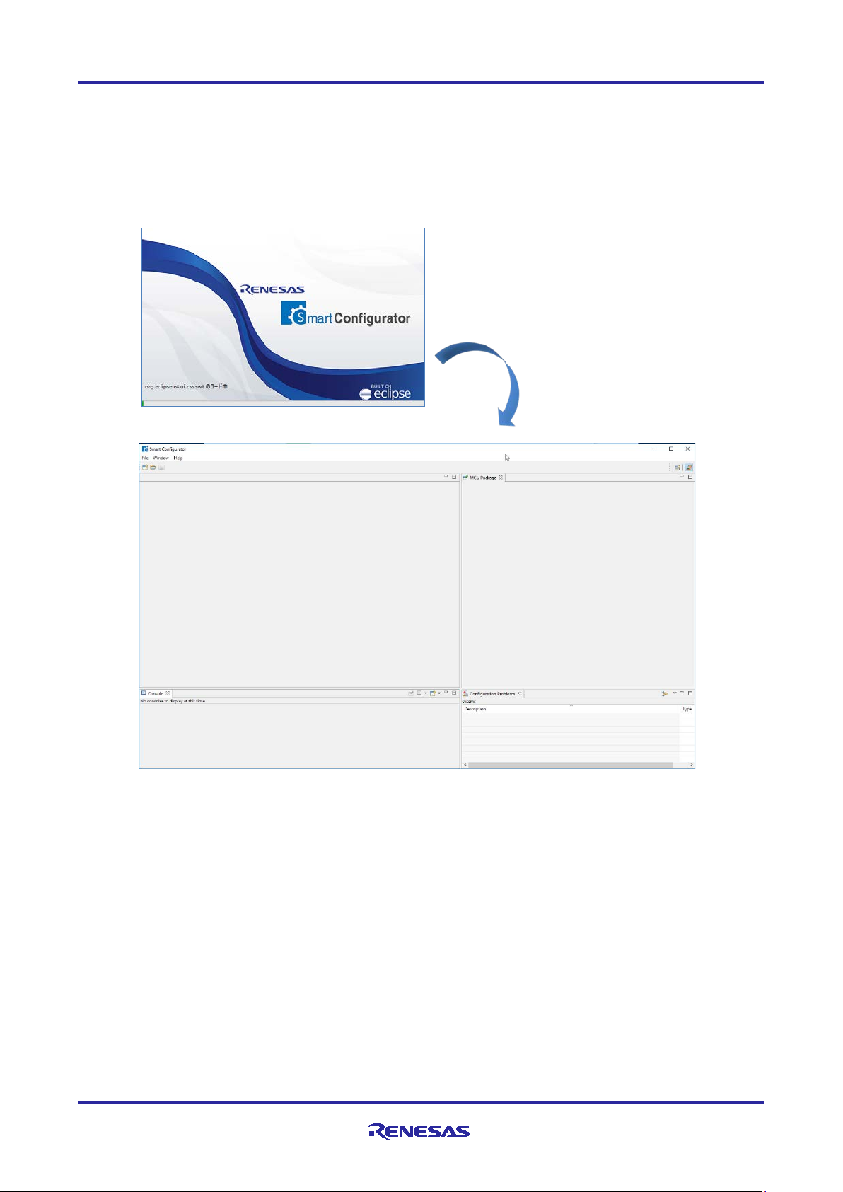
3.2 Starting the Smart Configurator
Select [Smart Configurator for RH850 Vx.x.x] of [Renesas Electronics Smart Configura tor] from the Windows start
menu. The main window of the Smart Configurator will be starting.
Note: Please replace Vx.x.x with your versio n.
Figure 3-2 Starting of Smart Configurator
R20AN0536EJ0100 Rev.1.00 Page 7 of 43
Jan 25, 2019
Page 8

RH850 Smart Configurator User’s Guide: IAREW, MULTI
(1)
(2)
(3)
(4)
(5)
(6)
(6)
3.3 Create and loading a configuration file
Smart Configurator saves and refers to the configuration file (*. scfg) the configuration information of the
microcontroller, build tool, peripheral function, pin function etc. used in the project.
3.3.1 Creating a New Configuration File
On the main windo w, click the [New Configuration File] b utto n to display the [New Smart Configuration File]
dialog box.
(1) In [Platform:], select the device.
(2) In [Toolchain:], select the toolchain.
To use the IAR compiler, select "IAR RH850 Toolchain".
To use the GHS compiler, select "GHS RH850 Toolchain".
(3) In [File name:], enter the file name.
(4) Confirm [Location:]. If you want to change it, click [Bro wse] and sele c t the save destination.
(5) To set the RTOS, click [Next]. When “IAR RH850 Toolchain" is selected, RTOS can’t be set.
(6) Click [Finish] to create the configuration file.
Figure 3-3 Create a Configuration File
If you select [RIV] in the RTOS setting, you can select non-OS management inte rrupts / OS ma na ge me nt int er r upt s fo r
component interrupts. For details, refer to "4.5.1, Interrupt prio rity level and OS management s ettings".
3.3.2 Opening an Existing Configuration File
On the main windo w, click the [Opening an Existing Configuration File] button to display the [Open] dialog box.
Figure 3-4 Opening an Existing Configuration File
R20AN0536EJ0100 Rev.1.00 Page 8 of 43
Jan 25, 2019
Page 9
RH850 Smart Configurator User’s Guide: IAREW, MULTI
(1)
(2)
(3)
(4)
(5)
(6)
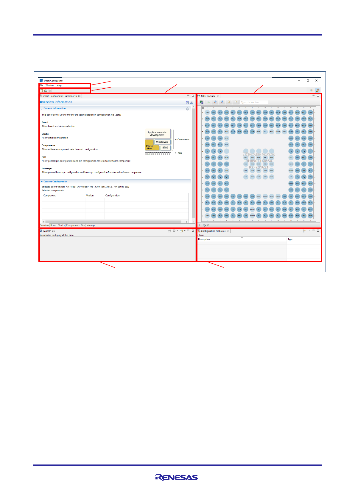
3.4 Window
The main window is displ ayed when the Smart Configurator is started . The configur ation of the window is shown in
Figure 3-5, Ma in Window.
(1) Menu bar
(2) Main tool bar
(3) Smart Configurator view
(4) MCU Package view
(5) Console view
(6) Configuration Problems view
Figure 3-5 Main Window
R20AN0536EJ0100 Rev.1.00 Page 9 of 43
Jan 25, 2019
Page 10

RH850 Smart Configurator User’s Guide: IAREW, MULTI
Menu
Details
File
New
The dialog box [New Smart Configuration File], whic h is used to create a
new configuration file, is displayed.
Open
The dialog box [Open], which opens an existin g configuration file, is
displayed.
Save
Saves a configuration file with the same name.
Restart
Smart Configurator is re-started.
Exit
Execution of the Smart Configurator is terminated.
Window
Preference
The dialog box [Preference], which is used to specify the properties of the
configuration file, is displayed.
Show view
The dialog box [Show view], which is used to set the view of the window,
is displayed.
Help
Help Contents
The help menu is displayed.
About
The version information is displayed.
Toolbar button
Related menu item
[File] → [New Smart Configuration File]
[File] → [Open]
[File] → [Save]
3.4.1 Main menu
Table 3-1, Main Menu Items, lists the items of the mai n me nu.
Table 3-1 Main Menu Items
3.4.2 Toolbar
Some functions of the main menu are allocated to the buttons on the toolbar. Table 3-2, Toolbar Buttons and Related
Menu Items, shows the description of those tool buttons.
Table 3-2 Toolbar Buttons and Related Menu Items
R20AN0536EJ0100 Rev.1.00 Page 10 of 43
Jan 25, 2019
Page 11
RH850 Smart Configurator User’s Guide: IAREW, MULTI
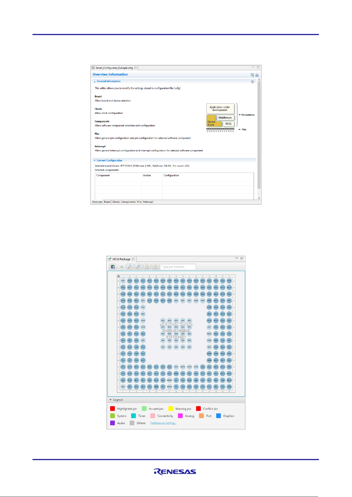
3.4.3 Smart Configurator view
The Smart Configurator view consists of six pages: [Overvie w i nformation], [Board], [Clocks], [Components], [Pins],
and [Interrupts]. Select a page by clicking on a tab; the displayed page will be changed.
Figure 3-6 Smart Configurator View
3.4.4 MCU Package view
Display the MCU package. You can save r otation, enla rgement, r ed uction, and MCU package view of the display to the
image file. You can also confirmation pin assignment and change it.
Figure 3-7 MCU Package View
R20AN0536EJ0100 Rev.1.00 Page 11 of 43
Jan 25, 2019
Page 12

RH850 Smart Configurator User’s Guide: IAREW, MULTI
3.4.5 Console view
The console displays details of changes to the configuration made in the Smart Configurator or MCU Package view.
Figure 3-8 Console View
3.4.6 Configuration Problems view
The Configuration Problems view displays problems with peripheral functions, interrupts, and pin conflicts.
Figure 3-9 Configuration Problems View
R20AN0536EJ0100 Rev.1.00 Page 12 of 43
Jan 25, 2019
Page 13
RH850 Smart Configurator User’s Guide: IAREW, MULTI
Button
Operation explanation
Yes
Change to the selected device.
No
It does not change the device.
Save and continue
After savi ng the current configurat ion contents to the configuration file, change to the
selected device.
Continue
Changes to the selected device without saving the current configuration contents to
the configuration file .
Cancel
It does not change the device.
4. Setting of Peripheral Modules
You can select peripheral modules from the Smart Configurator view.
4.1 Board setting
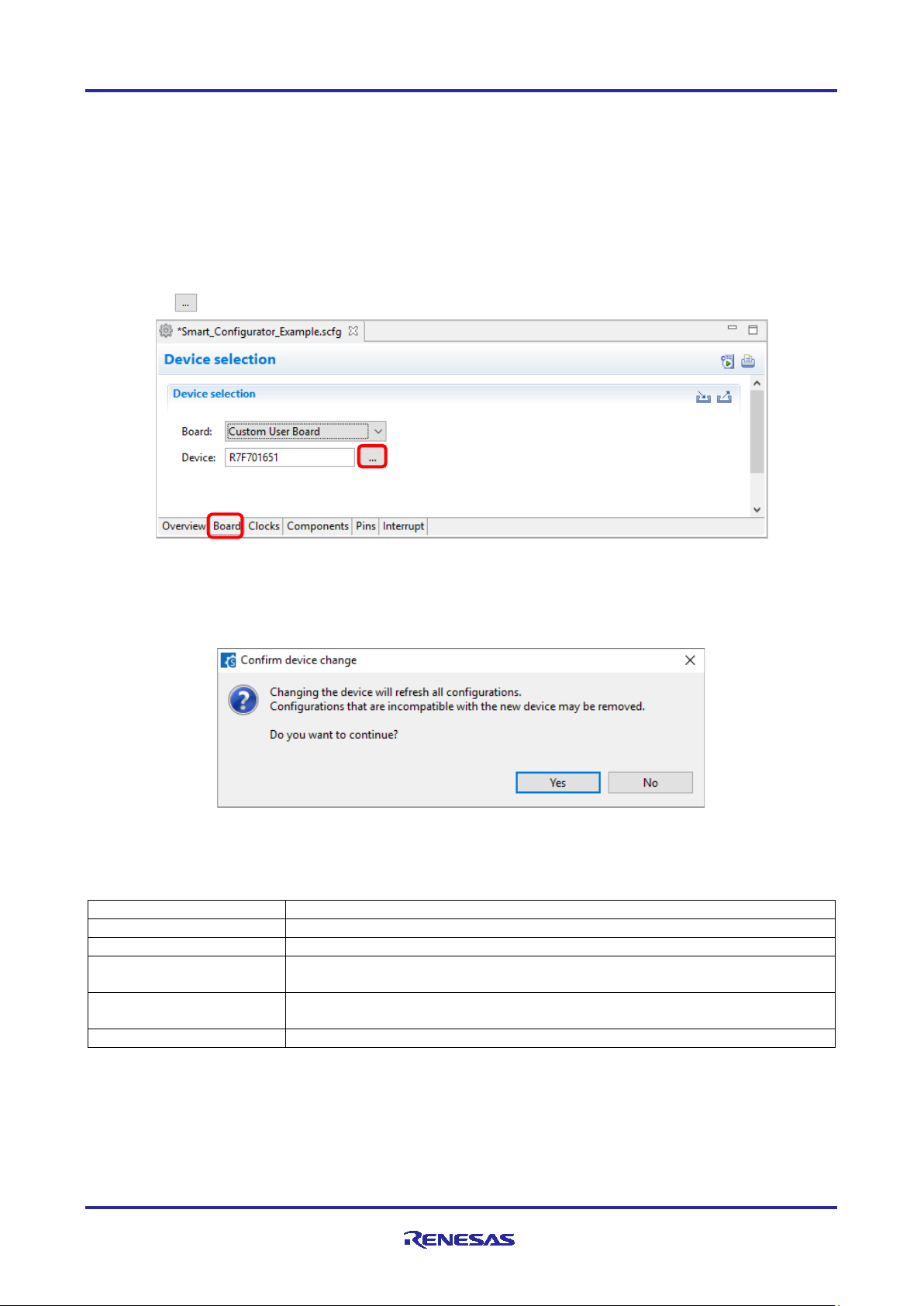
On the [Board] page, you can select boards and change devices.
4.1.1 Selecting the device
Click on the [ ] button to select a device.
Figure 4-1 Selecting the Device
The following message i s displayed when changing the device. For each button operation, refer to "Table 4-1, Device
change confirmation operation list".
Figure 4-2 Confirm Device Change
Table 4-1 Device Change Confirmation Operation List
R20AN0536EJ0100 Rev.1.00 Page 13 of 43
Jan 25, 2019
Page 14
RH850 Smart Configurator User’s Guide: IAREW, MULTI
Button
Operation explanation
Save and continue
After savi ng the current configurat ion contents to the configuration file, change to the
selected device.
Continue
Changes to the selected device without saving the current configuration contents to
the configuration file .
Cancel
It does not change the device.
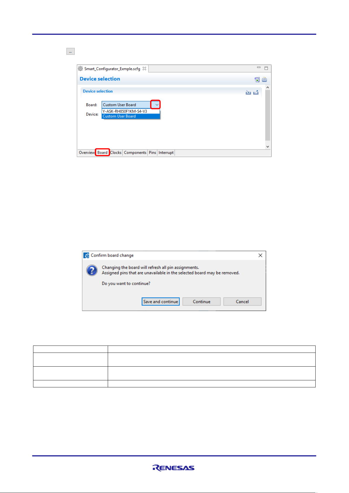
4.1.2 Selecting the board
Click on the [ ] b ut ton to select a device. When peripheral functions are configured by board selection, pins are
automatically set according to board connection.
Figure 4-3 Selecting the Board
The following items are changed according to the configuration of the selected board.
• Pin assignment
• Frequency of the main clock
• Frequency of the sub-clock
• Target device
If you change the board , the message s hown in “Figure 4-2” or the following message will be displayed. For each
button operation, refer to "Table 4-2, Board Change Confirmation Operation List".
Figure 4-4 Confirm Board Change
Table 4-2 Board Change Confirmation Operation List
R20AN0536EJ0100 Rev.1.00 Page 14 of 43
Jan 25, 2019
Page 15

RH850 Smart Configurator User’s Guide: IAREW, MULTI
4.1.3 Import board configuration
The board setting is defined in bdf (Board Description File). Follow the procedure below to import board configuration.
(1) Click on the [ (Import board setting)] button and select a desired bdf file.
(2) The board of the imported settings is added to the board selection menu.
Figure 4-5 Import of Board Configuration (bdf format)
Once a board setting file is imported, the added board is also displayed in the board selection menu of other projects for
the same device group.
4.1.4 Export board configuration
The current main clock frequency, sub clock frequency and pin assignment settings can be exported as board
configuration. Follow the procedure below to export the board configuration.
(1) Click on the [ (Export board setting)] button on the [Board] tabbed page.
(2) Select the output location and specify a name (Display Name) for the file to be exported.
Figure 4-6 Export of Board Configuration (bdf forma t)
R20AN0536EJ0100 Rev.1.00 Page 15 of 43
Jan 25, 2019
Page 16

RH850 Smart Configurator User’s Guide: IAREW, MULTI
(a)
(b)
(2)
(1)
4.2 Clock settings
On the [Clocks] page, set the clock. The [Clocks] page setting is used as the clock source for each component. Set the
clock before configuring the component.
The clocks setting is performed in the following procedure.
(1) Set the clock oscillator circuit.
(2) Sets the clock source to be supplied to the CPU and peripheral functions.
(a) When you move the mouse o n the screen, the clock signal is displayed in blue.
(b) Click on the screen to select the clock selector.
Figure 4-7 Clock Settings
R20AN0536EJ0100 Rev.1.00 Page 16 of 43
Jan 25, 2019
Page 17

RH850 Smart Configurator User’s Guide: IAREW, MULTI
Component tree
(1)
(2)
(3)
4.3 Software component settings
Drivers can be combined as software components on the [Components] page. Added components are displayed in the
component tree at the left of the page.
Figure 4-8 Component Page
4.3.1 Adding component
The following describes the procedure for adding a component.
(1) Click on the [ (Add component)] icon.
Figure 4-9 Adding Components
(2) Select a component from the list in the [Software Component Selection] page of the [New Component] dialo g
box (e.g. PWM Output Fu nction).
(3) Click on [Next].
Figure 4-10 Selection of Software Components
R20AN0536EJ0100 Rev.1.00 Page 17 of 43
Jan 25, 2019
Page 18

RH850 Smart Configurator User’s Guide: IAREW, MULTI
(4)
(6)
(5)
(1)
(2)
(3)
(4)
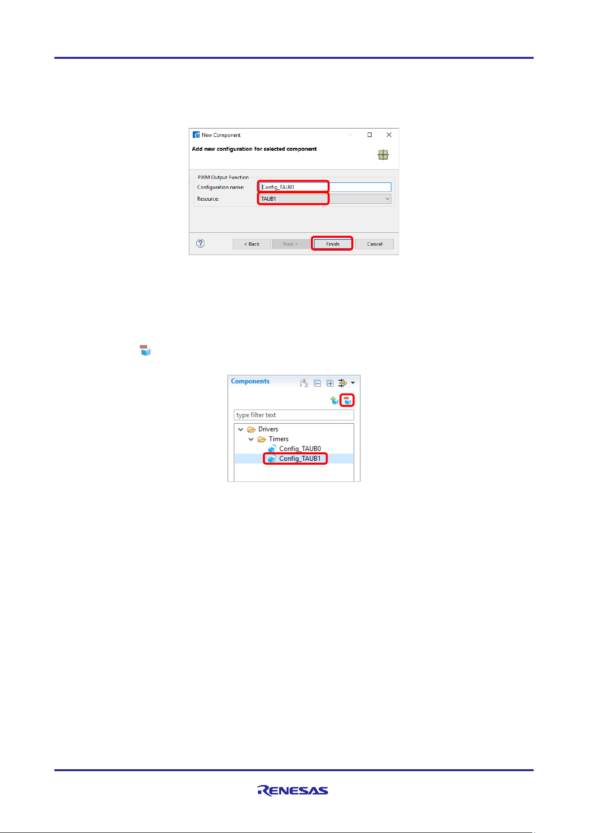
(4) Specify an appropriate configuration name in the [Add new configuration for selected component] page or use
the default name (e.g. Config_TAUB0).
(5) Select a hardware resource or use the default resource (e.g. TAUB0).
(6) Click on [Finish]. The component is added to the component tree.
Figure 4-11 Add New Configuration for Selected Component (e.g. TAUB0)
4.3.2 Switching between the component view and hardware view
The Smart Configurator also provides a function for adding a new c omponent by directly clicking a node in the
Components tree . To use this function, you need to switch the view of the Components tree from the component view to
the hardware view.
(1) Click on the [ (View Menu)] icon and select [Show by Hardware View]. The Components tree will display
the components in a hardware resource hierarchy.
Figure 4-12 Switch to [Show by Hardware View]
(2) Double-click on a hardware resource node (e.g. TAUB10 under Timer Array Unit B1) to open the [New
Component] dialog box.
(3) Select a component from the list (e.g. PWM Output Function) in the [Software Component Selection] page.
(4) Click the [Next].
Figure 4-13 Adding CG Components form the Har dware View
R20AN0536EJ0100 Rev.1.00 Page 18 of 43
Jan 25, 2019
Page 19
RH850 Smart Configurator User’s Guide: IAREW, MULTI
(5)
(7)
(2)
(1)
(6)
(5) Specify an appropriate configuration name in the [Add new configuration for selected component] page or use
the default name (e.g. Config_TAUB1).
(6) Select a hardware resource or use the default resource (e.g. TAUB1).
(7) Click on [Finish]. The component is added to the component tree.
Figure 4-14 Add New Configuration for Selected Component (e.g. TAUB1)
4.3.3 Deleting a software component
Follow the procedure below to removing a software component.
(1) Select a software component from the Components tree.
(2) Click on the [ (Remove component)] icon. The selected software is removed from the component tree. The
selected software component will be removed from the Components tree.
Figure 4-15 Removing a Component
R20AN0536EJ0100 Rev.1.00 Page 19 of 43
Jan 25, 2019
Page 20
RH850 Smart Configurator User’s Guide: IAREW, MULTI
(1)
(2) b.
(2) c.
(2) d.
(2) a.
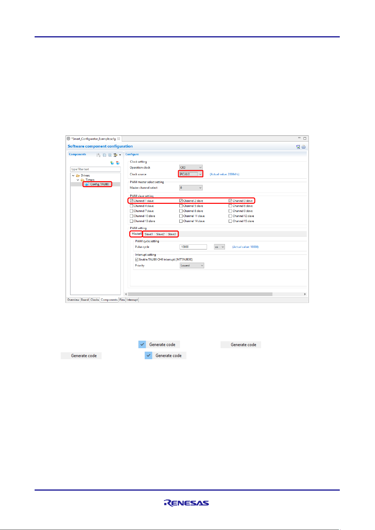
4.3.4 Component configuration settings
Follow the procedure below to setting the component configuration.
(1) Click the component in the component tree. (e.g. Config_TAUB0).
(2) Configure the driver in the [Configure] panel to the right of the Components tree. The Figure 4-16 is an
example.
a. Select [PCLK/2] in the item of [Clock source].
b. Select channel 1 slave, channel 2 s l ave, channel 3 slave.
c. Set the [Pulse cycle] on the [Master0] tab.
d. Set [Duty value] for each of the [Slave 1], [Slave 2], and [Slave 3] tabs.
Figure 4-16 Component Configuration Settings
The code generation of the component is set to enabled by d e fau lt.
Right click on the compo nent and cli ck [ ], it changes t o [ ] and no code is generated.
Clicking [ ] will change to [ ] and generate code.
R20AN0536EJ0100 Rev.1.00 Page 20 of 43
Jan 25, 2019
Page 21
RH850 Smart Configurator User’s Guide: IAREW, MULTI
(1)
(2)
(3)
(4)
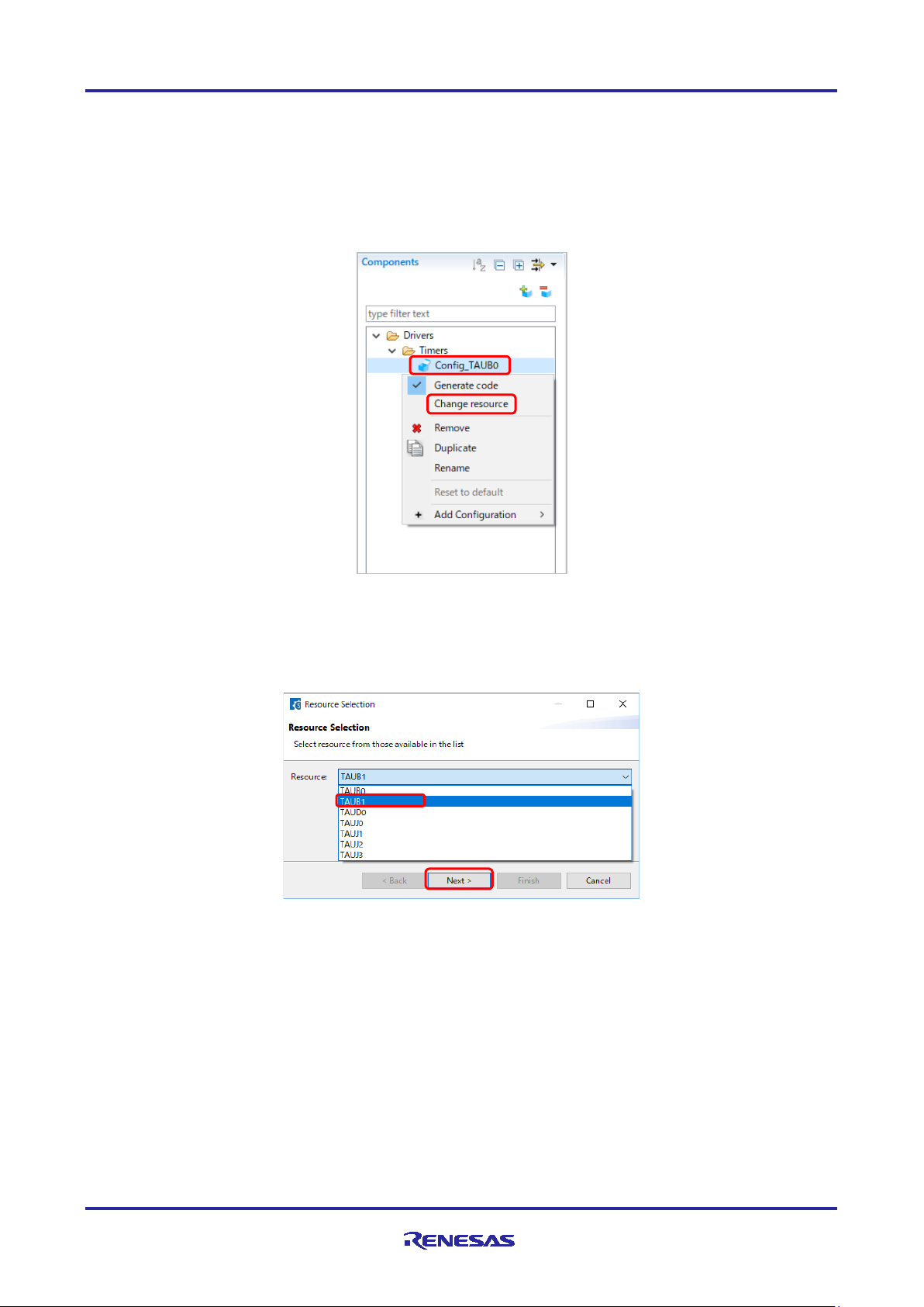
4.3.5 Component resource change
You can change the resource of the component (e.g. change from TAUB0 to TAUB1). Compatible configurations can
be migrated from the current resource to the newly selected resource.
Follow the procedure below to change the resource.
(1) Right-click on a component (e.g. Config_TAUB0).
(2) Select [Change resource] from the context menu.
Figure 4-17 Resource Change
(3) Select a new resource in the [ Resource Selection] dialog box (e.g. TAUB1).
(4) The [Next] button will be active; click on it.
Figure 4-18 Select a New Resource
R20AN0536EJ0100 Rev.1.00 Page 21 of 43
Jan 25, 2019
Page 22
RH850 Smart Configurator User’s Guide: IAREW, MULTI
(6)
(8)
(7)
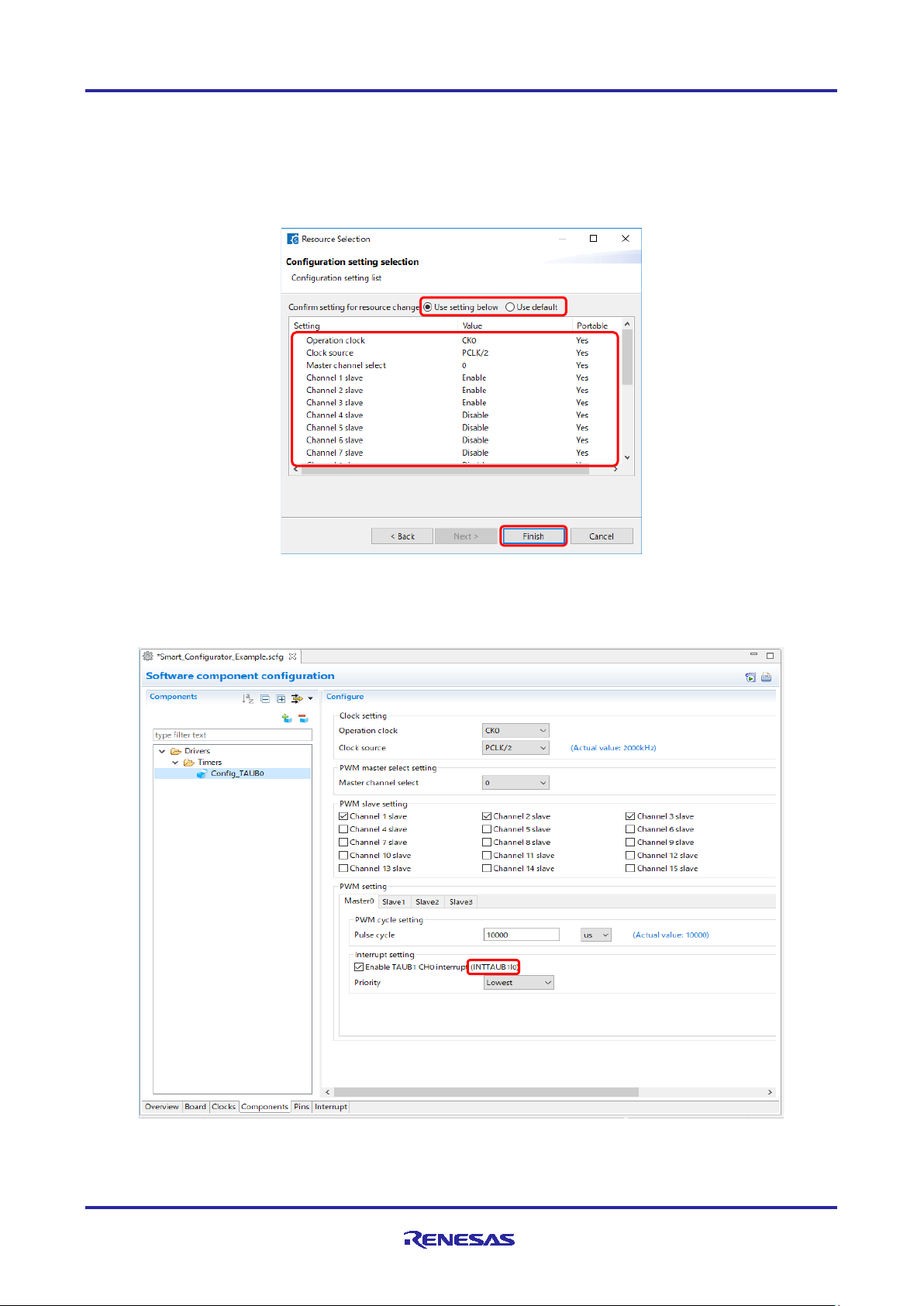
(5) The configuration information is displayed on the [Configuration setting selection] page of the [Select Resource]
dialog.
(6) Check the portability of the settings.
(7) Select whether to use the lis ted or default settings.
(8) Click on [Finish].
Figure 4-19 Confirm New Resource Settings
The resource is automatically changed (e.g. changed INTTAUB0I0 to INTTAUB1I0).
Figure 4-20 Resource Changed Automatically
R20AN0536EJ0100 Rev.1.00 Page 22 of 43
Jan 25, 2019
Page 23
RH850 Smart Configurator User’s Guide: IAREW, MULTI
(9)
(10)
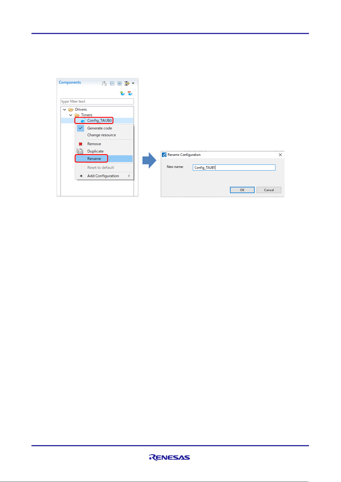
To change the configuration name, follow the procedure below.
(1) Right-click on the component.
(2) Select [Rename] to rename the configuration (e.g. change Config_TAUB0 to Config_TAUB1).
Figure 4-21 Renaming the Configuration
R20AN0536EJ0100 Rev.1.00 Page 23 of 43
Jan 25, 2019
Page 24
RH850 Smart Configurator User’s Guide: IAREW, MULTI
You can sort the display
You can sort the displa y
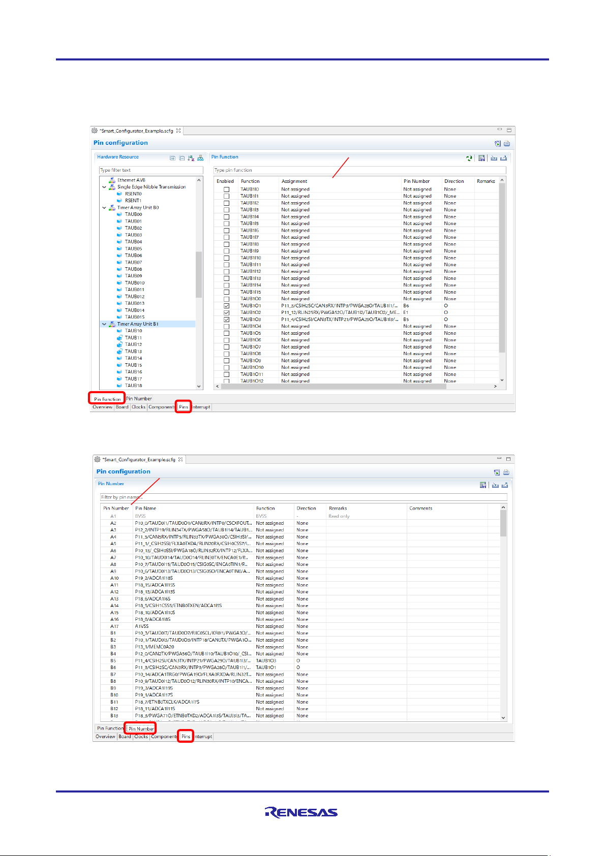
4.4 Pin settings
The [Pins] page is used for allocating pin functions. You can switch the display by clicking on the [Pin Function] and
[Pin Number] tabs. The [Pin Function] list shows the pin functions for each of the peripheral functions, and the [Pin
Number] list shows all pins in order of pin number.
by clicking the title.
Figure 4-22 [Pins] Page ([Pin Function])
by clicking the title.
R20AN0536EJ0100 Rev.1.00 Page 24 of 43
Jan 25, 2019
Figure 4-23 [Pins] Page ([Pin Number])
Page 25
RH850 Smart Configurator User’s Guide: IAREW, MULTI
(1)
(2)
(3)
(4)-(a)
(4)-(b)
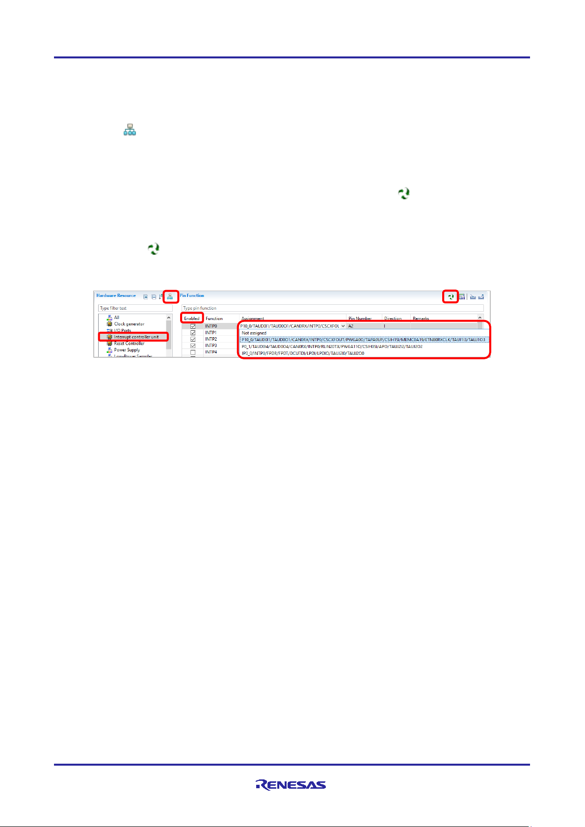
4.4.1 Assign pins to resources
In the Pins page, assign pin to the resource used by the component. Pin assignment can be done in either [Pin Function]
list or [Pin Number] list.
The proce dure for pin as s ignment in t he [Pin Function] list is described below.
(1) Click on [ (Show by Hardware Resource or Software Components)] to switch to the software component
view.
(2) Select the target software component (e.g. Interrupt controller unit).
(3) Click the [Enabled] header to sort by pins used.
(4) Pin assignment is performed with the [Assignment], [Pin Number] column, or [ (Next group of pins for the
selected resource)] button.
(a) Click [Assignment] or [Pin Number] and assign a terminal from the list (e.g. change from P0_1 to P10_0
with [Assi gnment]).
(b) Click the [ (Next group of pins for the selected resource)] button and change the pin assignment. Each
time you click, the pin with the function switches.
Figure 4-24 Pin Assignments in the [Pin function] List
When the component is set, the check box in the [Enabled] column is checked. Pin assignment is possible even when
the component is not set. If pin assignment is done without component being set, we will display "No component is
using this p in" in the [Remarks] column.
Note: The current ve rsion of Sma rt Configurator does not support t he component view for the [ Pins] page.
Use the Hardware Resource view to change the pin assignment.
R20AN0536EJ0100 Rev.1.00 Page 25 of 43
Jan 25, 2019
Page 26

RH850 Smart Configurator User’s Guide: IAREW, MULTI
(1)
(2)
(3)
(a)
4.4.2 Pin setting using MCU package
Follow the procedure below to assign pins in the MCU Package view.
(1) Zoom in to the view b y clicking the [ (Zoom in)] butto n o r sc r olling the view with the mous e wheel.
(2) Right-click on the target pin.
(3) Select the signal to be assigned to the pin.
Figure 4-25 Assigning Pins Using the MCU Package View
(a) The color of the pins can be customized through [Preference Setting...].
R20AN0536EJ0100 Rev.1.00 Page 26 of 43
Jan 25, 2019
Page 27

RH850 Smart Configurator User’s Guide: IAREW, MULTI
(1)
(1)
4.4.3 Export pin settings
You can expo rt pin assignment settings in XML format. Exported files can be imported into projects of the same device
family. Follow the procedure below to export the pin settings.
(1) Click on the [ (Export board setting)] button on the [Pins] page.
(2) In the [Export] dialog, enter th e file name to export.
Figure 4-26 Export Pin Settings (XML format)
The Smart Configurator can also export the pin settings to a CSV file. Click on the [ (Save the list to .csv file)] button
on the [Pins] page.
4.4.4 Import pin settings
You can import XML format files including pin assignment settings. When you import a file, the terminal assignment is
reflected. Follow the procedure below to import the pin settings.
(1) Click on the [ (Import board setting)] button on the [Pins] page.
(2) In the [Import] dialog, enter the file name to import.
Figure 4-27 Import Pin Settings (XML format)
R20AN0536EJ0100 Rev.1.00 Page 27 of 43
Jan 25, 2019
Page 28

RH850 Smart Configurator User’s Guide: IAREW, MULTI
(1)
(2)
4.5 Interrupt settings
Check and set the interrupts of the peripheral modules that have been selected on the [Components] page.
Figure 4-28 [Interrupts] Page
4.5.1 Changing the interrupt priority level and OS management setting
When an inter rupt is used in a configuration on the [Components] page, the status of t he interrupt will be changed to
"Used". To display the used interrupts only, cl ick on the [ (Show used interrupts)] button.
(1) The interrupt priority level can be c han ged in the [priority] column. Setting the pr iority level is reflected in the
configuration settings of the component.
(2) The [OS management] column becomes active for a project that uses RTOS (RI850V4). Selecting a checkbox in
the column outputs the c orresponding interrup t function in the interr upt format tha t can be managed by the OS.
Figure 4-29 Interrupt Settings
R20AN0536EJ0100 Rev.1.00 Page 28 of 43
Jan 25, 2019
Page 29

RH850 Smart Configurator User’s Guide: IAREW, MULTI
5. Managing Conflicts
Adding co mponents, set t ing pins and interrupts may cause problems related to resource mismatch. This information will
be displayed in the [Configuration Problems view]. User can refer to the information displayed to fix the conflict issues.
5.1 Resource conflicts
When two software components are configured to use the same resource (for e.g. TAUB1), an error mark ( ) will be
displayed in the [Components tree].
The [Configuration Problems view] will display messages on peripheral conflicts to inform the user in which software
configurations peripheral conflicts have been detected.
Figure 5-1 Resource Conflicts
R20AN0536EJ0100 Rev.1.00 Page 29 of 43
Jan 25, 2019
Page 30

RH850 Smart Configurator User’s Guide: IAREW, MULTI
5.2 Resource pin conflicts
When multiple pin functions are assigned to the same pin, an error mark is displayed in the tree and [Pin Function]
list on the [Pins] page.
Figure 5-2 Pin Conflicts
The detailed information regarding conflicts is displayed in the [Configuration Problems view].
Figure 5-3 Pin Conflict Message
To resolve a conflict, right-click on the node with an error mark on the tre e and select [Resolve conflict].
Figure 5-4 Resolving Pin Conflicts
The pins of the selected node will be re-assigned to other pins.
R20AN0536EJ0100 Rev.1.00 Page 30 of 43
Jan 25, 2019
Page 31

RH850 Smart Configurator User’s Guide: IAREW, MULTI
6. Generating Source Code
6.1 Generating Source Code File
Output a source file for the configured details by clicking on the [ (Generate Code)] button i n the Smart Configurator
view.
Figure 6-1 Generating a Source File
The Smart Configurator generates a source file in <ConfigurationFileDir>\src\smc_gen. If your Smart Configurator has
already generated a file, a backup copy of that file is also generated (refer to the section 6.6, Backing up Generated
Source Code).
6.2 Configuration of Generated Files and File Names
Figure 6-2, Configuration of Generated Files and File Names, shows the folders and files output by the Smart
Configurator. "ConfigName" indic ates the configuration name set in the compone nt.
Figure 6-2 Configuration of Generated Files and File Names
R20AN0536EJ0100 Rev.1.00 Page 31 of 43
Jan 25, 2019
Page 32
RH850 Smart Configurator User’s Guide: IAREW, MULTI
Folder
File
Description
This folder is generated for the components that are added to the
ConfigName (configuration name).
{ConfigName}.c
This file contains functions to initial iz e driver
This file contains interrupt service routines and functio ns for user
User can add codes and functions in the dedicated user code areas.
{ConfigName}.h
This is header file for {ConfigName}.c and {ConfigName}_user.c
This file is always generated.
configured in the [Pins] tabbed page (except I/O Ports).
Pin.h
This file is always generated.
This folder is always generated.
of the same peripheral function.
r_cg_xxx.h
(*1)
These files are always generated.
This file is always generated.
settings in the [Clocks] page.
r_cs_cgc.h
This file is always generated.
This header file contains macro definitions to initialize clocks.
This file contains functions to be added to R_CGC_Create.
User can add codes and functions in the dedicated user code areas.
This file is always generated.
This file is always generated.
drivers.
r_cg_main.c
This file is always generated. It d e fine s the main() function.
This file is always generated.
R_Systeminit also calls the functions for initializing clocks.
r_cg_userdefine.h
This file is always generated.
r_smc_interrupt.c
This file is always generated.
r_smc_interrupt.h
This file is always generated.
Table 6-1 Description of Generated File
{ConfigName} -
project. API functions in this folder are named after the
(R_ConfigName_Create) and perform operations that are driver-
specific, e.g. start (R_ConfigName_Start) and stop
(R_ConfigName_Stop).
{ConfigName}_user.c
to add code after the driver initialization (R_ConfigName_Create).
r_pincfg Pin.c
It is a reference of pin function initialization for all peripherals
It contains the function prototypes of pin settings in Pin.c
general -
It contains header files and source files commonly used by dr ive rs
r_cg_cgc.c
r_cs_cgc_user.c
r_cg_intvector.c
r_cg_macrodriver.h
r_cg_ systeminit.c
Note *1: xxx is the name of a component.
The files contain macro definitions for setting SFR registers.
It contains the initialization of clock sources in accordance with the
It contains interrupt vector table definitions.
This header file contains common macro definitions used in
It contains R_Systeminit that ca lls all driver initialization functions
with the name R_ConfigName_Create.
User can add macro definitions in the dedicated user code areas.
R20AN0536EJ0100 Rev.1.00 Page 32 of 43
Jan 25, 2019
Page 33
RH850 Smart Configurator User’s Guide: IAREW, MULTI
Folder
File
Macros/Functions
Description
general
r_cg_cgc.c
R_CGC_Create
This API function initializes clocks.
function.
Macros related to clocks
These macros are for clocks initialization in
R_CGC_Create.
r_cg_cgc_user.c
R_CGC_Create_UserInit
This API function is for user to add code in
R_CGC_Create after the CGC initialization.
6.3 Initializing Clocks
Configurations of clock source in [Clocks] page are generated in \src\smc_gen\r_config folder.
Figure 6-3 Clocks Source Configuration
Table 6-2 Clock Source File Description
r_cg_cgc.h
R_Systeminit in r_cg_systeminit.c will call this
function during execution of the main()
R20AN0536EJ0100 Rev.1.00 Page 33 of 43
Jan 25, 2019
Page 34

RH850 Smart Configurator User’s Guide: IAREW, MULTI
Folder
File
Function
Description
This API function initializes pins used by this
function.
Folder
File
Function
Description
This function contains the initializ a tion codes of
except I/O ports.
6.4 Initializing Pins
Pin configuration settings are generated by the compone nt into source files as shown in (1) and (2) below.
(1) Pins initialization for drivers with { ConfigName}
The pin function is initialized with R_ConfigName_Create of \src\smc_gen\{ConfigName}\{ConfigName}.c.
Table 6-3 File to Initialize Pins
{ConfigName} {ConfigName}.c R_ConfigName_Create
driver. R_Systeminit in r_cg_hardware_setup.c
will call this function before enterin g main()
(1) Reference pins initialization codes
Refer to Pin.c in the \src\smc_gen\r_pincfg folder for the initializatio n code of all pin functi ons set on the [Pins]
page (except I/O ports).
Table 6-4 Reference File for Initialization of All Pins
r_pincfg Pin.c R_Pins_Create
all pins function configured at [Pins] page
Jan 25, 2019
R20AN0536EJ0100 Rev.1.00 Page 34 of 43
Page 35
RH850 Smart Configurator User’s Guide: IAREW, MULTI
No
Item
Folder
File
Description
Interrupt priority level settings are initialized in
function.
OS
{ConfigName}
The interr upt functions defined in t his file are
managed by the OS.
(1)
(2)
6.5 Initializing Interrupts
Configurati ons in [Interrupt] page are generated in few source files.
Figure 6-4 Interrupt Configuration
Table 6-5 Interrupt Generation File Description
(1) Priority {ConfigName} {ConfigName}.c
R_ConfigName_Create in this file.
R_Systeminit in r_cg_
function during execution of the main()
systeminit.c will call this
(2)
management
{ConfigName}_user.c
output in the interrupt format that c an be
6.6 Backing up Generated Source Code
The smart configurator has a source code backup function.
<ConfigurationFileDir>\trash\<Date-and-Time>
The Smart Configurator generates a backup folder for the previously generated source code when new code is generated
by clicking on [ ]. <Date-and-Time> indicates the date and time when the backup folder is created after code
generation.
R20AN0536EJ0100 Rev.1.00 Page 35 of 43
Jan 25, 2019
Page 36

RH850 Smart Configurator User’s Guide: IAREW, MULTI
7. Loading generated files in Integrated development environment
Load source code outputted by Smart Configurator on Integrated Development Environ ment Platform.
7.1 Loading in IAR Embedded Workbench
When IAR environment is selected for the compiler to be used, Smart Configurator also outputs the project connection
file (.ipcf) together with the source file. The project connection file contains source file registration information. It is not
necessary for the user to add or delete source files after configuration c hange in the Smart Configurator.
The usage procedure is as follows.
(1) Select [Add Project Connection..] from the [Project] menu of IAR Embedded Workbench.
(2) The [Add Project Connection] dialog is displayed. Select [IAR Project Connection] and click [OK].
(3) In the [Select IAR Project Connection File] dialog box, browse to the folder where the configuration file is
saved, select the project connection file (.ipcf), and click the [Open] button.
(4) The source file output by the Smart Configurator is added to the workspace.
7.2 Loading in GHS MULTI
When GHS environment is selected for the compiler to be used, Smart Configurator also outputs the project connection
file (.gpj) together with the so urc e file. The project connection file contains source file r egistration information. It is not
necessary for the user to add or delete source files after configuration c hange in the S ma r t Co n figurator.
The usage procedure is as follows.
(1) Select [Open Project Manager ...] from the MULTI [Components] menu.
(2) As the [Select a project to open] dialog box appears, browse to the folder where the configuration file is saved,
select default.gpj, and click the [Open] button.
(3) The source file output by the Smart Configurator is added to the workspace.
R20AN0536EJ0100 Rev.1.00 Page 36 of 43
Jan 25, 2019
Page 37
RH850 Smart Configurator User’s Guide: IAREW, MULTI
/* Start user code for xxxx. Do not edit comment generated here */
8. Creating User Programs
The component type of the Smart Configurator has [code generation]. This section describes how to add custom code of
[code generation].
8.1 Adding Custom Code in the Case of Code Generator
When [Code Generator] is selected as the component type, if files which have the same name already exist, new code
will be merge d only with the existing code that is between the comments below.
/* End user code. Do not edit comment generated here */
In the case of [Code Generator], three files are generated for each of the specified peripheral functions. The file names
are “Config_xxx.h”, “Config_xxx.c”, and “Config_xxx_user.c” as the default, with “xxx” represent ing the name of the
peripheral module. For example, “xxx” will be “TAUB1” for the compare-match timer (resource TAUB1). The
comments to indica te where to add custom code are at the start and end of each of the t hre e files. Comments to i ndic a te
where to add user code are also added to the interrupt function for the peripheral module corresponding to
Config.xxx_user.c. The following examples are for TAUB1 (Config_ TAUB1_user.c).
/*******************************************************************************
Pragma directive
*******************************************************************************/
/* Start user code for pragma. Do not edit comment generated here */
/* End user code. Do not edit comment generated here */
/*******************************************************************************
Includes
*******************************************************************************/
#include "r_cg_macrodriver.h"
#include "r_cg_userdefine.h"
#include "Config_TAUB1.h"
/* Start user code for include. Do not edit comment generated here */
/* End user code. Do not edit comment generated here */
/*******************************************************************************
Global variables and functions
*******************************************************************************/
/* Start user code for global. Do not edit comment generated here */
/* End user code. Do not edit comment generated here */
/*******************************************************************************
* Function Name: R_Config_TAUB1_Create_UserInit
* Description : This function ad ds user code after initializing the TAUB1 channel
* Arguments : None
* Return Val ue : None
*******************************************************************************/
void R_Config_TAUB1_Create_UserInit(void)
{
/* Start user code for user init. Do not edit comment generated here */
/* End user code. Do not edit comment generated here */
}
R20AN0536EJ0100 Rev.1.00 Page 37 of 43
Jan 25, 2019
Page 38
RH850 Smart Configurator User’s Guide: IAREW, MULTI
/*******************************************************************************
* Function Name: r_Config_TAUB1_channel0_interrupt
* Description : This function is TAUB10 interrupt service routine
* Arguments : None
* Return Val ue : None
*******************************************************************************/
#pragma interrupt r_Config_TAUB1_channel0_interrupt(enable=false, channel=256, fpu=true,
callt=false)
void r_Config_TAUB1_channel0_interrupt(void)
{
/* Start user code for r_Config_TAUB1_channel0_interrupt. Do not edit comment generated here
*/
/* End user code. Do not edit comment generated here */
}
/* Start user code for adding. Do not edit comment generated here */
/* End user code. Do n ot edit comment generated here */
R20AN0536EJ0100 Rev.1.00 Page 38 of 43
Jan 25, 2019
Page 39

RH850 Smart Configurator User’s Guide: IAREW, MULTI
9. Gene r ating Reports
The Smart Configurator can output t he configuration information of the project to the report. Follow the procedure
below to generate a report.
9.1 Report on Configuration
A report is output in response to clicking on the [ (Generate Report)] button in the Smart Co nfigurator view.
Figure 9-1 Output of a Report on the Configuration (as a Text File)
Figure 9-2 Dialog Box for Output of a Report
R20AN0536EJ0100 Rev.1.00 Page 39 of 43
Jan 25, 2019
Page 40

RH850 Smart Configurator User’s Guide: IAREW, MULTI
9.2 Configuration of Pin Function List and Pin Number List (in csv Format)
A list of the configuration of pin functions and pin numbers (whichever is selected at the time) is output in response to
clicking on [ (Save the list to .csv file)] on the [Pins] page of the Smart Configurator view.
Figure 9-3 Output of a List of Pin Functions or Numbers (in csv Format)
9.3 Image of MCU Package (in png Format)
An image of the MCU package is output in response to clicking on the [ (Save Package View to external image file)]
button of the [MCU Package] view.
Figure 9-4 Outputting a Figure of MCU Package (in png Format)
R20AN0536EJ0100 Rev.1.00 Page 40 of 43
Jan 25, 2019
Page 41

RH850 Smart Configurator User’s Guide: IAREW, MULTI
10. Help
10.1 Help
Refer to the help system for detailed information on the Smart Configurator.
Figure 10-1 Help Menu
The help system can also be activated from the [Overview] page.
Figure 10-2 Quick Start
R20AN0536EJ0100 Rev.1.00 Page 41 of 43
Jan 25, 2019
Page 42

RH850 Smart Configurator User’s Guide: IAREW, MULTI
11. Documents for Reference
User’s Manual: Hardware
Obtain the latest version of the manual from the web site of Renesas Electronics.
Technical Update/Technical News
Smart Configurator: Guide on Sample Project for RH850/F1KM Device (R01AN4422)
User’s Manua l: Development Enviro nment
Obtain the latest version of the manual from each company web site.
R20AN0536EJ0100 Rev.1.00 Page 42 of 43
Jan 25, 2019
Page 43

RH850 Smart Configurator User’s Guide: IAREW, MULTI
Website and Support
Renesas Electronics Website
http://www.renesas.com/
Inquiries
http://www.renesas.com/contact/
All trademarks and registered trademarks are the property of their respective owners.
R20AN0536EJ0100 Rev.1.00 Page 43 of 43
Jan 25, 2019
Page 44

Rev.
Date
Description
Page
Summary
1.00
Jan 25, 2019
-
First edition issued
Revision History
Page 45

General Precautions in the Handling of Microprocessing Unit and Microcontroller
Unit Products
The following usage notes are applicable to all Microprocessing unit and Microcontroller unit products from Renesas. For detailed usage notes on the
products covered by this document, refer to the relevant sections of the document as well as any technical updates that have been issued for the products.
1. Precaution against Electrostatic Discharge (ESD)
A strong electrical field, when exposed to a CMOS device, can cause destruction of the gate oxide and ultimately degrade the device operation. Steps
must be taken to stop the generation of static electricity as much as possible, and quickly dissipate it when it occurs. Environmental control must be
adequate. When it is dry, a humidifier should be used. This is recommended to avoid using insulators that can easily build up static electricity.
Semiconductor devices must be stored and transported in an anti-static container, static shielding bag or conductive material. All test and
measurement tools including work benches and floors must be grounded. The operator must also be grounded using a wrist strap. Semiconductor
devices must not be touched with bare hands. Similar precautions must be taken for printed circuit boards with mounted semiconductor devices.
2. Processing at power-on
The state of the product is undefined at the time when power is supplied. The states of internal circuits in the LSI are indeterminate and the states of
register settings and pins are undefined at the time when power is supplied. In a finished product where the reset signal is applied to the external reset
pin, the states of pins are not guaranteed from the time when power is supplied until the reset process is completed. In a similar way, the states of pins
in a product that is reset by an on-chip power-on reset function are not guaranteed from the time when power is supplied until the power reaches the
level at which resetting is specified.
3. Input of signal during power-off state
Do not input signals or an I/O pull-up power supply while the device is powered off. The current injection that results from input of such a signal or I/O
pull-up power supply may cause malfunction and the abnormal current that passes in the device at this time may cause degradation of internal
elements. Follow the guideline for input signal during power-off state as described in your product documentation.
4. Handling of unused pins
Handle unused pins in accordance with the directions given under handling of unused pins in the manual. The input pins of CMOS products are
generally in the high-impedance state. In operation with an unused pin in the open-circuit state, extra electromagnetic noise is induced in the vicinity of
the LSI, an associated shoot-through current flows internally, and malfunctions occur due to the false recognition of the pin state as an input signal
become possible.
5. Clock signals
After applying a reset, only release the reset line after the operating clock signal becomes stable. When switching the clock signal during program
execution, wait until the target clock signal is stabilized. When the clock signal is generated with an external resonator or from an external oscillator
during a reset, ensure that the reset line is only released after full stabilization of the clock signal. Additionally, when switching to a clock signal
produced with an external resonator or by an external oscillator while program execution is in progress, wait until the target clock signal is stable.
6. Voltage application waveform at input pin
Waveform distortion due to input noise or a reflected wave may cause malfunction. If the input of the CMOS device stays in the area between V
(Max.) and V
input level is fixed, and also in the transition period when the input level passes through the area between V
7. Prohibition of access to reserved addresses
Access to reserved addresses is prohibited. The reserved addresses are provided for possible future expansion of functions. Do not access these
addresses as the correct operation of the LSI is not guaranteed.
8. Differences between products
Before changing from one product to another, for example to a product with a different part number, confirm that the change will not lead to problems.
The characteristics of a microprocessing unit or microcontroller unit products in the same group but having a different part number might differ in terms
of internal memory capacity, layout pattern, and other factors, which can affect the ranges of electrical characteristics, such as characteristic values,
operating margins, immunity to noise, and amount of radiated noise. When changing to a product with a different part number, implement a systemevaluation test for the given product.
(Min.) due to noise, for example, the device may malfunction. Take care to prevent chattering noise from entering the device when the
IH
(Max.) and VIH (Min.).
IL
IL
Page 46

Notice
1. Descriptions of circuits, software and other related information in this document are provided only to illustrate the operation of semiconductor products and application examples. You are fully responsible for
the incorporation or any other use of the circuits, software, and information in the design of your product or system. Renesas Electronics disclaims any and all liability for any losses and damages incurred by
you or third parties arising from the use of these circuits, software, or information.
2. Renesas Electronics hereby expressly disclaims any warranties against and liability for infringement or any other claims involving patents, copyrights, or other intellectual property rights of third parties, by or
arising from the use of Renesas Electronics products or technical information described in this document, including but not limited to, the product data, drawings, charts, programs, algorithms, and application
examples.
3. No license, express, implied or otherwise, is granted hereby under any patents, copyrights or other intellectual property rights of Renesas Electronics or others.
4. You shall not alter, modify, copy, or reverse engineer any Renesas Electronics product, whether in whole or in part. Renesas Electronics disclaims any and all liability for any losses or damages incurred by
you or third parties arising from such alteration, modification, copying or reverse engineering.
5. Renesas Electronics products are classified according to the following two quality grades: “Standard” and “High Quality”. The intended applications for each Renesas Electronics product depends on the
product’s quality grade, as indicated below.
"Standard": Computers; office equipment; communications equipment; test and measurement equipment; audio and visual equipment; home electronic appliances; machine tools; personal electronic
"High Quality": Transportation equipment (automobiles, trains, ships, etc.); traffic control (traffic lights); large-scale communication equipment; key financial terminal systems; safety control equipment; etc.
Unless expressly designated as a high reliability product or a product for harsh environments in a Renesas Electronics data sheet or other Renesas Electronics document, Renesas Electronics products are
not intended or authorized for use in products or systems that may pose a direct threat to human life or bodily injury (artificial life support devices or systems; surgical implantations; etc.), or may cause
serious property damage (space system; undersea repeaters; nuclear power control systems; aircraft control systems; key plant systems; military equipment; etc.). Renesas Electronics disclaims any and all
liability for any damages or losses incurred by you or any third parties arising from the use of any Renesas Electronics product that is inconsistent with any Renesas Electronics data sheet, user’s manual or
other Renesas Electronics document.
6. When using Renesas Electronics products, refer to the latest product information (data sheets, user’s manuals, application notes, “General Notes for Handling and Using Semiconductor Devices” in the
reliability handbook, etc.), and ensure that usage conditions are within the ranges specified by Renesas Electronics with respect to maximum ratings, operating power supply voltage range, heat dissipation
characteristics, installation, etc. Renesas Electronics disclaims any and all liability for any malfunctions, failure or accident arising out of the use of Renesas Electronics products outside of such specified
ranges.
7. Although Renesas Electronics endeavors to improve the quality and reliability of Renesas Electronics products, semiconductor products have specific characteristics, such as the occurrence of failure at a
certain rate and malfunctions under certain use conditions. Unless designated as a high reliability product or a product for harsh environments in a Renesas Electronics data sheet or other Renesas
Electronics document, Renesas Electronics products are not subject to radiation resistance design. You are responsible for implementing safety measures to guard against the possibility of bodily injury, injury
or damage caused by fire, and/or danger to the public in the event of a failure or malfunction of Renesas Electronics products, such as safety design for hardware and software, including but not limited to
redundancy, fire control and malfunction prevention, appropriate treatment for aging degradation or any other appropriate measures. Because the evaluation of microcomputer software alone is very difficult
and impractical, you are responsible for evaluating the safety of the final products or systems manufactured by you.
8. Please contact a Renesas Electronics sales office for details as to environmental matters such as the environmental compatibility of each Renesas Electronics product. You are responsible for carefully and
sufficiently investigating applicable laws and regulations that regulate the inclusion or use of controlled substances, including without limitation, the EU RoHS Directive, and using Renesas Electronics
products in compliance with all these applicable laws and regulations. Renesas Electronics disclaims any and all liability for damages or losses occurring as a result of your noncompliance with applicable
laws and regulations.
9. Renesas Electronics products and technologies shall not be used for or incorporated into any products or systems whose manufacture, use, or sale is prohibited under any applicable domestic or foreign laws
or regulations. You shall comply with any applicable export control laws and regulations promulgated and administered by the governments of any countries asserting jurisdiction over the parties or
transactions.
10. It is the responsibility of the buyer or distributor of Renesas Electronics products, or any other party who distributes, disposes of, or otherwise sells or transfers the product to a third party, to notify such third
party in advance of the contents and conditions set forth in this document.
11. This document shall not be reprinted, reproduced or duplicated in any form, in whole or in part, without prior written consent of Renesas Electronics.
12. Please contact a Renesas Electronics sales office if you have any questions regarding the information contained in this document or Renesas Electronics products.
(Note 1) “Renesas Electronics” as used in this document means Renesas Electronics Corporation and also includes its directly or indirectly controlled subsidiaries.
(Note 2) “Renesas Electronics product(s)” means any product developed or manufactured by or for Renesas Electronics.
equipment; industrial robots; etc.
(Rev.4.0-1 November 2017)
SALES OFFICES
Refer to "http://www.renesas.com/" for the latest and detailed information.
Renesas Electronics Corporation
TOYOSU FORESIA, 3-2-24 Toyosu, Koto-ku, Tokyo 135-0061, Japan
Renesas Electronics America Inc.
1001 Murphy Ranch Road, Milpitas, CA 95035, U.S.A.
Tel: +1-408-432-8888, Fax: +1-408-434-5351
Renesas Electronics Canada Limited
9251 Yonge Street, Suite 8309 Richmond Hill, Ontario Canada L4C 9T3
Tel: +1-905-237-2004
Renesas Electronics Europe Limited
Dukes Meadow, Millboard Road, Bourne End, Buckinghamshire, SL8 5FH, U.K
Tel: +44-1628-651-700
Renesas Electronics Europe GmbH
Arcadiastrasse 10, 40472 Düsseldorf, Germany
Tel: +49-211-6503-0, Fax: +49-211-6503-1327
Renesas Electronics (China) Co., Ltd.
Room 1709 Quantum Plaza, No.27 ZhichunLu, Haidian District, Beijing, 100191 P. R. China
Tel: +86-10-8235-1155, Fax: +86-10-8235-7679
Renesas Electronics (Shanghai) Co., Ltd.
Unit 301, Tower A, Central Towers, 555 Langao Road, Putuo District, Shanghai, 200333 P. R. China
Tel: +86-21-2226-0888, Fax: +86-21-2226-0999
Renesas Electronics Hong Kong Limited
Unit 1601-1611, 16/F., Tower 2, Grand Century Place, 193 Prince Edward Road West, Mongkok, Kowloon, Hong Kong
Tel: +852-2265-6688, Fax: +852 2886-9022
Renesas Electronics Taiwan Co., Ltd.
13F, No. 363, Fu Shing North Road, Taipei 10543, Taiwan
Tel: +886-2-8175-9600, Fax: +886 2-8175-9670
Renesas Electronics Singapore Pte. Ltd.
80 Bendemeer Road, Unit #06-02 Hyflux Innovation Centre, Singapore 339949
Tel: +65-6213-0200, Fax: +65-6213-0300
Renesas Electronics Malaysia Sdn.Bhd.
Unit 1207, Block B, Menara Amcorp, Amcorp Trade Centre, No. 18, Jln Persiaran Barat, 46050 Petaling Jaya, Selangor Darul Ehsan, Malaysia
Tel: +60-3-7955-9390, Fax: +60-3-7955-9510
Renesas Electronics India Pvt. Ltd.
No.777C, 100 Feet Road, HAL 2nd Stage, Indiranagar, Bangalore 560 038, India
Tel: +91-80-67208700, Fax: +91-80-67208777
Renesas Electronics Korea Co., Ltd.
17F, KAMCO Yangjae Tower, 262, Gangnam-daero, Gangnam-gu, Seoul, 06265 Korea
Tel: +82-2-558-3737, Fax: +82-2-558-5338
© 2019 Renesas Electronics Corporation. All rights reserved.
http://www.renesas.com
Colophon 7.2
 Loading...