

Page 1

To our customers,
Old Company Name in Catalogs and Other Documents
On April 1st, 2010, NEC Electronics Corporation merged with Renesas Technology
Corporation, and Renesas Electronics Corporation took over all the business of both
companies. Therefore, although the old company name remains in this document, it is a valid
Renesas Electronics document. We appreciate your understanding.
Renesas Electronics website: http://www.renesas.com
April 1
Renesas Electronics Corporation
Issued by: Renesas Electronics Corporation (http://www.renesas.com)
st
, 2010
Send any inquiries to http://www.renesas.com/inquiry
.
Page 2

Notice
1. All information included in this document is current as of the date this document is issued. Such information, however, is
subject to change without any prior notice. Before purchasing or using any Renesas Electronics products listed herein, please
confirm the latest product information with a Renesas Electronics sales office. Also, please pay regular and careful attention to
additional and different information to be disclosed by Renesas Electronics such as that disclosed through our website.
2. Renesas Electronics does not assume any liability for infringement of patents, copyrights, or other intellectual property rights
of third parties by or arising from the use of Renesas Electronics products or technical information described in this document.
No license, express, implied or otherwise, is granted hereby under any patents, copyrights or other intellectual property rights
of Renesas Electronics or others.
3. You should not alter, modify, copy, or otherwise misappropriate any Renesas Electronics product, whether in whole or in part.
4. Descriptions of circuits, software and other related information in this document are provided only to illustrate the operation of
semiconductor products and application examples. You are fully responsible for the incorporation of these circuits, software,
and information in the design of your equipment. Renesas Electronics assumes no responsibility for any losses incurred by
you or third parties arising from the use of these circuits, software, or information.
5. When exporting the products or technology described in this document, you should comply with the applicable export control
laws and regulations and follow the procedures required by such laws and regulations. You should not use Renesas
Electronics products or the technology described in this document for any purpose relating to military applications or use by
the military, including but not limited to the development of weapons of mass destruction. Renesas Electronics products and
technology may not be used for or incorporated into any products or systems whose manufacture, use, or sale is prohibited
under any applicable domestic or foreign laws or regulations.
6. Renesas Electronics has used reasonable care in preparing the information included in this document, but Renesas Electronics
does not warrant that such informatio n is error free. Renesas Electronics assumes no liability whatsoever for any damages
incurred by you resulting from errors in or omissions from the information included herein.
7. Renesas Electronics products are classified according to the following three quality grades: “Standard”, “High Quality”, and
“Specific”. The recommended applications for each Renesas Electronics product depends on the product’s quality grade, as
indicated below. You must check the quality grade of each Renesas Electronics product before using it in a particular
application. You may not use any Renesas Electronics product for any application categorized as “Specific” without the prior
written consent of Renesas Electronics. Further, you may not use any Renesas Electronics product for any application for
which it is not intended without the prior written consent of Renesas Electronics. Renesas Electronics shall not be in any way
liable for any damages or losses incurred by you or third parties arising from the use of any Renesas Electronics product for an
application categorized as “Specific” or for which the product is not intended where you have failed to obtain the prior written
consent of Renesas Electronics. The quality grade of each Renesas Electronics product is “Standard” unless otherwise
expressly specified in a Ren esas E lectronics data sheets or dat a books, etc.
“Standard”: Computers; office equipment; communications equipment; test and measurement equipment; audio and visual
equipment; home electron ic appliances; machine tools; personal electronic equipment; and industrial robots.
“High Quality”: Transportation equipment (automobiles, trains, ships, etc.); traffic control systems; anti-disaster systems; anti-
crime systems; safety equipment; and medical equipment not specifically designed for life support.
“Specific”: Aircraft; aerospace equipment; submersible repeaters; nuclear reactor control systems; medical equipment or
systems for life support (e.g. artificial life support devices or systems), surgical implantations, or healthcare
intervention (e.g. excision, etc.), and any other appl i cations or purposes that pose a d irect threat to human life.
8. You should use the Renesas Electronics products described in this document within the range specified by Renesas Electronics,
especially with respect to the maximum rating, operating supply voltage range, movement power voltage range, heat radiation
characteristics, installation and other product characteristics. Renesas Electronics shall have no liability for malfunctions or
damages arising out of the use of Renesas Electronics products beyond such specified ranges.
9. Although Renesas Electronics endeavors to improve the quality and reliability of its products, semiconductor products have
specific characteristics such as t he occu rrence o f failure at a certai n rate an d malfunct io ns under cert ain u se con dition s. Further,
Renesas Electronics prod ucts are not subject to radiation resistance design. Please be sure to implement safety measures to
guard them against the possibility of physical injury, and injury or damage caused by fire in the event of the failure of a
Renesas Electronics product, such as safety design for hardware and software including but not limited to redundancy, fire
control and malfunction prevention, appropriate treatment for aging degradation or any other appropriate measures. Because
the evaluation of microcomputer software alone is very difficult, please evaluate the safety of the final products or system
manufactured by you.
10. Please contact a Renesas Electronics sales office for details as to environmental matters such as the environmental
compatibility of each Renesas Electronics product. Please use Renesas Electronics products in compliance with all applicable
laws and regulations that regulate the inclusion or use of controlled substances, including without limitation, the EU RoHS
Directive. Renesas Electronics assumes no liability for damages or losses occurring as a result of your noncompliance with
applicable laws and regulations.
11. This document may not be reproduced or duplicated, in any form, in whole or in part, without prior written consent of Renesas
Electronics.
12. Please contact a Renesas Electronics sales office if you have any questions regarding the information contained in this
document or Renesas Electronics products, or if you have any other inquiries.
(Note 1) “Renesas Electronics” as used in this document means Renesas Electronics Corporation an d also includes its majority-
owned subsidiaries.
(Note 2) “Renesas Electronics product(s)” means any product developed or manufactured by or for Renesas Electronics.
Page 3

User’s Manual
High-performance Embedded
Workshop V.4.05
User’s Manual
Renesas Microcomputer Development
Environment System
Rev.1.00 2008.11
Page 4

Notes regarding these materials
1. This document is provided for reference purposes only so that Renesas customers may select the appropriate
Renesas products for their use. Renesas neither makes warranties or representations with respect to the
accuracy or completeness of the information contained in this document nor grants any license to any intellectual
property rights or any other rights of Renesas or any third party with respect to the information in this document.
2. Renesas shall have no liability for damages or infringement of any intellectual property or other rights arising out
of the use of any information in this document, including, but not limited to, product data, diagrams, charts,
programs, algorithms, and application circuit examples.
3. You should not use the products or the technology described in this document for the purpose of military
applications such as the development of weapons of mass destruction or for the purpose of any other military
use. When exporting the products or technology described herein, you should follow the applicable export
control laws and regulations, and procedures required by such laws and regulations.
4. All information included in this document such as product data, diagrams, charts, programs, algorithms, and
application circuit examples, is current as of the date this document is issued. Such information, however, is
subject to change without any prior notice. Before purchasing or using any Renesas products listed in this
document, please confirm the latest product information with a Renesas sales office. Also, please pay regular
and careful attention to additional and different information to be disclosed by Renesas such as that disclosed
through our website. (http://www.renesas.com)
5. Renesas has used reasonable care in compiling the information included in this document, but Renesas
assumes no liability whatsoever for any damages incurred as a result of errors or omissions in the information
included in this document.
6. When using or otherwise relying on the information in this document, you should evaluate the information in light
of the total system before deciding about the applicability of such information to the intended application.
Renesas makes no representations, warranties or guaranties regarding the suitability of its products for any
particular application and specifically disclaims any liability arising out of the application and use of the
information in this document or Renesas products.
7. With the exception of products specified by Renesas as suitable for automobile applications, Renesas products
are not designed, manufactured or tested for applications or otherwise in systems the failure or malfunction of
which may cause a direct threat to human life or create a risk of human injury or which require especially high
quality and reliability such as safety systems, or equipment or systems for transportation and traffic, healthcare,
combustion control, aerospace and aeronautics, nuclear power, or undersea communication transmission. If you
are considering the use of our products for such purposes, please contact a Renesas sales office beforehand.
Renesas shall have no liability for damages arising out of the uses set forth above.
8. Notwithstanding the preceding paragraph, you should not use Renesas products for the purposes listed below:
(1) artificial life support devices or systems
(2) surgical implantations
(3) healthcare intervention (e.g., excision, administration of medication, etc.)
(4) any other purposes that pose a direct threat to human life
Renesas shall have no liability for damages arising out of the uses set forth in the above and purchasers who
elect to use Renesas products in any of the foregoing applications shall indemnify and hold harmless Renesas
Technology Corp., its affiliated companies and their officers, directors, and employees against any and all
damages arising out of such applications.
9. You should use the products described herein within the range specified by Renesas, especially with respect to
the maximum rating, operating supply voltage range, movement power voltage range, heat radiation
characteristics, installation and other product characteristics. Renesas shall have no liability for malfunctions or
damages arising out of the use of Renesas products beyond such specified ranges.
10. Although Renesas endeavors to improve the quality and reliability of its products, IC products have specific
characteristics such as the occurrence of failure at a certain rate and malfunctions under certain use conditions.
Please be sure to implement safety measures to guard against the possibility of physical injury, and injury or
damage caused by fire in the event of the failure of a Renesas product, such as safety design for hardware and
software including but not limited to redundancy, fire control and malfunction prevention, appropriate treatment
for aging degradation or any other applicable measures. Among others, since the evaluation of microcomputer
software alone is very difficult, please evaluate the safety of the final products or system manufactured by you.
11. In case Renesas products listed in this document are detached from the products to which the Renesas products
are attached or affixed, the risk of accident such as swallowing by infants and small children is very high. You
should implement safety measures so that Renesas products may not be easily detached from your products.
Renesas shall have no liability for damages arising out of such detachment.
12. This document may not be reproduced or duplicated, in any form, in whole or in part, without prior written
approval from Renesas.
13. Please contact a Renesas sales office if you have any questions regarding the information contained in this
document, Renesas semiconductor products, or if you have any other inquiries.
Page 5

High-performance Embedded Workshop Introduction
Introduction
The High-performance Embedded Workshop is a powerful development environment for embedded applications
targeted at Renesas micro-controllers. The main features are:
• A configurable build engine that allows you to set-up compiler, assembler and linker options by using GUI.
• An integrated text editor with user customizable syntax coloring to improve code readability.
• A configurable environment, which allows you to run your own tools.
• An integrated debugger, which allows you to build and debug in the same application.
• Version control support.
The High-performance Embedded Workshop has been designed with two key aims; firstly to provide you, the user,
with a set of powerful development tools and, secondly, to unify and present them in a way that is easy to use.
About This User’s Manual
This user’s manual describes the High-performance Embedded Workshop system. This user’s manual describes
information on the basic “look and feel” of the High-performance Embedded Workshop and customizing the Highperformance Embedded Workshop environment and detail the build and the debugging functions common to the Highperformance Embedded Workshop products. The figures in this document show the High-performance Embedded
Workshop operating with the SuperH family debugging platform.
The term “debugging platform” refers to an emulator or simulator/debugger that operates with the integrated
development environment “High-performance Embedded Workshop”.
For details on the debugging platform, see the user’s manual or online help information packaged with the emulator or
simulator.
This user’s manual does not intend to explain how to write C/C++ or assembly language programs, how to use any
particular operating system or how best to tailor code for the individual devices. These issues are left to the respective
user’s manuals.
The High-performance Embedded Workshop is customized in various languages. This user’s manual gives descriptions
on the English version of the High-performance Embedded Workshop applicatio n.
Document Conventions
This user’s manual uses the following typographic conventions:
Convention Meaning
[Menu -> Menu Option] ‘->’ is used to indicate menu options (for example, [File -> Save As]).
FILENAME.C Uppercase names are used to indicate filenames.
Key + Key Used to indicate required key presses. For example, CTRL+N means press the CT RL key
and then, whilst holding the CTRL key down, press the N key.
REJ10J1837-0100 Rev.1.00 Nov. 16, 2008
Page 6

High-performance Embedded Workshop Introduction
Figures
Some figures in this user’s manual may differ from the objects they represent.
Operating Environment for the High-performance Embedded Workshop
This user’s manual, online help, and release notes do not indicate that the correct operation of the High-performance
Embedded Workshop is guaranteed for a ny t y pes of host computers or peripheral devices.
Trademarks
Microsoft, MS-DOS, Visual SourceSafe, Windows and Windows Vista are either registered trademarks or trademarks
of Microsoft Corporation in the United States and/or other countries.
All other company and product names are registered trademarks or tr ademarks of their respective companies.
For inquiries about the contents of this document or product, email to your local d istributor.
Renesas Tools Homepage http://www.renesas.com/tools
REJ10J1837-0100 Rev.1.00 Nov. 16, 2008
Page 7

High-performance Embedded Workshop Contents
Contents
1. Overview......................................................................................................................................1
1.1 Workspaces, projects and files...................................................................................................................................1
1.2 Main window.............................................................................................................................................................1
1.2.1 Title bar...........................................................................................................................................................2
1.2.2 Menu bar.........................................................................................................................................................2
1.2.3 Toolbars ..........................................................................................................................................................3
1.2.4 Workspace window.........................................................................................................................................5
1.2.5 Editor window.................................................................................................................................................8
1.2.6 Output window................................................................................................................................................9
1.2.7 Status bar.......................................................................................................................................................12
1.3 Help system .............................................................................................................................................................12
1.4 Launching the High-performance Embedded Workshop.........................................................................................13
1.5 Creating a new workspace .......................................................................................................................................13
1.6 Opening a workspace...............................................................................................................................................14
1.7 Using old workspaces ..............................................................................................................................................15
1.8 Saving a workspace .................................................................................................................................................15
1.9 Closing a workspace................................................................................................................................................16
1.10 Exiting the High-performance Embedded Workshop..............................................................................................16
1.11 Component system overview...................................................................................................................................16
1.12 Management information files of High-performance Embedded Workshop...........................................................16
1.13 Overview of Configurations and Sessions...............................................................................................................17
1.14 Overview of Macro-Recording Support facility and Test Support facility..............................................................21
1.14.1 Example of test procedures...........................................................................................................................24
1.14.2 Step 1: Recording a macro............................................................................................................................25
1.14.3 Step 2: Editing a macro (viewing records)....................................................................................................27
1.14.4 Step 3: Playing a macro.................................................................................................................................28
1.14.5 Step 4: Creating a test suite...........................................................................................................................28
1.14.6 Step 5: Editing a test suite.............................................................................................................................28
1.14.7 Step 6: Creating a test image file ..................................................................................................................30
1.14.8 Step 7: Modifying the program before the test..............................................................................................32
1.14.9 Step 8: Viewing the test result (unmatched).................................................................................................33
1.14.10 Step 9: Modifying the program back and executing the test again................................................................34
1.14.11 Step 10: Viewing the test result (matched) ...................................................................................................34
2. Build Basics ...............................................................................................................................35
2.1 The build process.....................................................................................................................................................35
2.2 Configuring the Projects tab of the Workspace window..........................................................................................36
2.3 Project files ..............................................................................................................................................................38
2.3.1 Adding files to a project................................................................................................................................39
2.3.2 Drag and drop of files and folders.................................................................................................................40
2.3.3 Removing files from a project.......................................................................................................................41
2.3.4 Excluding a project file from build...............................................................................................................42
2.3.5 Including a project file in build.....................................................................................................................43
2.4 User folders in the workspace..................................................................................................................................43
2.5 File extensions and file groups ................................................................................................................................44
2.5.1 Associating an application with a file group.................................................................................................45
2.5.2 Creating a new file extension and file group.................................................................................................47
2.5.3 Creating a new file extension........................................................................................................................48
2.6 Setting build options ................................................................................................................................................49
2.7 Build configurations ................................................................................................................................................49
2.7.1 Selecting a build configuration .....................................................................................................................50
REJ10J1837-0100 Rev.1.00 Nov. 16, 2008
i
Page 8

High-performance Embedded Workshop Contents
2.7.2 Adding a new build configuration.................................................................................................................50
2.7.3 Removing a build configuration....................................................................................................................50
2.8 Building a project ....................................................................................................................................................51
2.8.1 Building individual files................................................................................................................................51
2.8.2 Building a project..........................................................................................................................................51
2.8.3 Building multiple projects.............................................................................................................................52
2.8.4 Stopping tool execution.................................................................................................................................52
2.8.5 Deleting intermediate and output files produced in building........................................................................53
2.8.6 Configuring the Build tab of the Output window..........................................................................................54
2.8.7 Controlling the content of the Build tab of the Output window....................................................................56
2.8.8 Displaying out of date files in the Workspace window.................................................................................56
2.9 File dependencies..................................................................................................................................................... 57
2.10 Configuring the Workspace window .......................................................................................................................60
2.11 Inserting a project into the workspace .....................................................................................................................61
2.12 Setting the current project........................................................................................................................................62
2.13 Specifying dependencies between projects..............................................................................................................63
2.14 Removing a project from the workspace .................................................................................................................64
2.15 Relative projects paths in the workspace.................................................................................................................64
3. Advanced Build Features...........................................................................................................65
3.1 The build process revisited ......................................................................................................................................65
3.1.1 What is a build?.............................................................................................................................................65
3.2 Creating a custom build phase.................................................................................................................................66
3.3 Ordering build phases ..............................................................................................................................................70
3.3.1 Build Order tab..............................................................................................................................................70
3.3.2 Build File Order tab ......................................................................................................................................73
3.3.3 File Mappings tab..........................................................................................................................................74
3.4 Setting custom build phase options..........................................................................................................................75
3.4.1 Options tab....................................................................................................................................................75
3.4.2 Output Files tab.............................................................................................................................................76
3.4.3 Dependent Files tab.......................................................................................................................................76
3.5 Controlling the build................................................................................................................................................77
3.6 Logging build output ...............................................................................................................................................78
3.7 Changing toolchain version .....................................................................................................................................78
3.8 Generating a makefile.............................................................................................................................................. 79
3.9 Using a makefile inside the High-performance Embedded Workshop system........................................................81
3.10 Customizing the High-performance Embedded Workshop linkage order...............................................................83
4. Using the Editor .........................................................................................................................86
4.1 Editor window .........................................................................................................................................................86
4.2 Working with multiple files.....................................................................................................................................87
4.3 Standard file operations ...........................................................................................................................................87
4.3.1 Creating a new file........................................................................................................................................87
4.3.2 Editing a file..................................................................................................................................................87
4.3.3 Saving a file ..................................................................................................................................................88
4.3.4 Opening a file................................................................................................................................................89
4.3.5 Closing files ..................................................................................................................................................90
4.3.6 Pop-up menu to close the window................................................................................................................91
4.4 Searching and navigating through files....................................................................................................................91
4.4.1 Finding text...................................................................................................................................................91
4.4.2 Finding text in multiple files.........................................................................................................................92
4.4.3 Replacing text ...............................................................................................................................................94
4.4.4 Jumping to a specified line............................................................................................................................95
4.5 Bookmarks...............................................................................................................................................................95
REJ10J1837-0100 Rev.1.00 Nov. 16, 2008
ii
Page 9

High-performance Embedded Workshop Contents
4.6 Printing a file ........................................................................................................................................................... 96
4.7 Configuring text layout............................................................................................................................................96
4.7.1 Page set-up....................................................................................................................................................96
4.7.2 Changing tabs................................................................................................................................................97
4.7.3 Auto indentation............................................................................................................................................98
4.8 Splitting a window...................................................................................................................................................98
4.9 Changing the editor font ..........................................................................................................................................99
4.10 Syntax coloring........................................................................................................................................................99
4.10.1 Changing text colors ...................................................................................................................................100
4.10.2 Creating new keywords...............................................................................................................................100
4.10.3 Enabling/disabling syntax coloring.............................................................................................................101
4.11 Templates...............................................................................................................................................................102
4.11.1 Defining a template.....................................................................................................................................102
4.11.2 Deleting a template .....................................................................................................................................104
4.11.3 Inserting a template.....................................................................................................................................104
4.12 Brace matching ......................................................................................................................................................104
4.13 Setting the read-only attribute for a file.................................................................................................................105
4.14 Preventing modification of files while debugging.................................................................................................105
4.15 Managing the editor columns.................................................................................................................................105
4.16 Showing/hiding the column header .......................................................................................................................106
4.17 Opening a file within the editor .............................................................................................................................107
4.18 Tooltip watch.........................................................................................................................................................107
4.19 Evaluate an expression...........................................................................................................................................108
5. Tools Administration ...............................................................................................................109
5.1 Tool locations ........................................................................................................................................................109
5.2 High-performance Embedded Workshop registration files ...................................................................................110
5.3 Registering a component .......................................................................................................................................111
5.4 Unregistering a component....................................................................................................................................112
5.5 Viewing and editing component properties ...........................................................................................................112
5.6 Technical support...................................................................................................................................................114
5.7 Using On-Demand components.............................................................................................................................115
5.8 Custom project types .............................................................................................................................................116
6. Customizing the Environment .................................................................................................118
6.1 Customizing the toolbars .......................................................................................................................................118
6.2 Customizing the Tools menu .................................................................................................................................120
6.3 Using custom placeholders....................................................................................................................................121
6.4 Using the workspace and project log facilities ......................................................................................................122
6.5 Configuring the help system ..................................................................................................................................123
6.6 Keyboard shortcut customization ..........................................................................................................................124
6.7 Scope of a control in the setup...............................................................................................................................125
6.7.1 Scope of a control in the Customize dialog box..........................................................................................125
6.7.2 Scope of a control in the Options dialog box..............................................................................................126
6.8 Specifying workspace options ...............................................................................................................................126
6.8.1 Opening the last workspace at start-up........................................................................................................126
6.8.2 Restoring files on opening a workspace......................................................................................................126
6.8.3 Displaying workspace information on opening a workspace......................................................................127
6.8.4 Saving the workspace before executing any tools.......................................................................................127
6.8.5 Prompting before saving a workspace.........................................................................................................127
6.8.6 Prompting before saving a session..............................................................................................................128
6.8.7 Enabling auto-backup facilities...................................................................................................................128
6.8.8 Setting the projects to load on workspace open..........................................................................................129
6.8.9 Specifying a default directory for new workspaces ....................................................................................129
6.9 Using an external editor.........................................................................................................................................130
REJ10J1837-0100 Rev.1.00 Nov. 16, 2008
iii
Page 10

High-performance Embedded Workshop Contents
6.10 Customizing the font in your views.......................................................................................................................132
6.11 Using the virtual desktop .......................................................................................................................................133
7. Version Control........................................................................................................................134
7.1 Selecting a Version Control System ......................................................................................................................135
7.2 Importing and exporting a set-up...........................................................................................................................136
8. Using the Custom Version Control System.............................................................................137
8.1 Defining Version Control menu options................................................................................................................137
8.1.1 System-defined menu options.....................................................................................................................138
8.1.2 User-defined menu options.........................................................................................................................139
8.2 Defining Version Control commands ....................................................................................................................140
8.3 Specifying arguments ............................................................................................................................................141
8.4 Specifying comments.............................................................................................................................................141
8.5 Executable return code...........................................................................................................................................141
8.6 Specifying file locations ........................................................................................................................................142
8.7 Specifying file locations example..........................................................................................................................143
8.8 Specifying environment.........................................................................................................................................144
8.9 Controlling execution of a Version Control System..............................................................................................144
8.10 Specifying a user name and password ...................................................................................................................145
8.11 Usage example of the Custom Version Control System........................................................................................146
8.11.1 Connecting the High-performance Embedde d Workshop with RCS..........................................................146
8.11.2 Connecting the High-performance Embedded Workshop with CVS..........................................................151
9. Using Visual SourceSafe .........................................................................................................158
9.1 Attaching Visual SourceSafe to a workspace ........................................................................................................158
9.2 Visual SourceSafe commands................................................................................................................................160
9.2.1 Adding files to Visual SourceSafe..............................................................................................................161
9.2.2 Removing files from Visual SourceSafe.....................................................................................................162
9.2.3 Getting read-only copy of files from Visual SourceSafe............................................................................162
9.2.4 Checking out writable copy of files from Visual SourceSafe..................................................................... 163
9.2.5 Checking in writable copy of files into Visual SourceSafe.........................................................................164
9.2.6 Viewing the status of files in Visual SourceSafe........................................................................................165
9.2.7 Undoing a check out command in Visual SourceSafe ................................................................................165
9.2.8 Viewing the history of files in Visual SourceSafe......................................................................................166
9.3 Visual SourceSafe command options ....................................................................................................................167
9.4 Version Control setup ............................................................................................................................................167
9.5 Specifying file locations ........................................................................................................................................167
9.6 Adding Visual SourceSafe commands...................................................................................................................169
10. Sharing Projects by Network Facilities....................................................................................171
10.1 Sharing projects by network facilities in a PC with Windows® XP Service Pack 2 or later.................................172
10.2 Enabling network facilities to share projects.........................................................................................................174
10.3 Setting the administrator user's password..............................................................................................................174
10.4 Adding new users to the system.............................................................................................................................175
10.5 Changing your password .......................................................................................................................................176
10.6 Note on using the network facilities to share projects ...........................................................................................176
11. Comparing Files.......................................................................................................................178
11.1 Opening the Difference window............................................................................................................................178
12. Navigation Facilities................................................................................................................181
12.1 C function and #define navigation component......................................................................................................183
12.2 C++ navigation component....................................................................................................................................183
12.3 Jump to a definition from the editor......................................................................................................................185
REJ10J1837-0100 Rev.1.00 Nov. 16, 2008
iv
Page 11

High-performance Embedded Workshop Contents
12.4 Drag and drop navigation items.............................................................................................................................186
12.5 Smart edit capability..............................................................................................................................................187
13. Map ..........................................................................................................................................189
13.1 Managing section settings......................................................................................................................................190
13.1.1 Opening the Map Section Information window..........................................................................................190
13.1.2 Entering/exiting the edit mode.................................................................................................................... 193
13.1.3 Adding a section group ...............................................................................................................................194
13.1.4 Adding a section..........................................................................................................................................194
13.1.5 Adding an overlay group.............................................................................................................................195
13.1.6 Automatically registering the unregistered section.....................................................................................195
13.1.7 Editing a selected item................................................................................................................................196
13.1.8 Setting the primary section..........................................................................................................................196
13.1.9 Setting a memory map ................................................................................................................................197
13.1.10 Automatically allocating the memory resource...........................................................................................197
13.1.11 Printing out the section settings tree ...........................................................................................................198
13.1.12 Viewing unallocated areas ..........................................................................................................................198
13.1.13 Viewing sections of size 0...........................................................................................................................198
13.1.14 Viewing the source code for the address.....................................................................................................198
13.1.15 Printing out the section list..........................................................................................................................199
13.2 Viewing symbols...................................................................................................................................................199
13.2.1 Opening the Map Symbol Information window..........................................................................................199
13.2.2 Printing out the map list..............................................................................................................................201
13.2.3 Finding symbols ..........................................................................................................................................201
13.2.4 Filtering the symbol information.................................................................................................................201
13.2.5 Viewing the source code for the address.....................................................................................................202
13.2.6 Printing out the symbol information ...........................................................................................................203
14. Using the Command Line ........................................................................................................204
14.1 Opening the Command Line window ....................................................................................................................204
14.2 Specifying a batch file...........................................................................................................................................207
14.3 Executing a batch file ............................................................................................................................................208
14.4 Stopping command execution................................................................................................................................208
14.5 Specifying a log file...............................................................................................................................................208
14.6 Starting or stopping logging ..................................................................................................................................209
14.7 Entering a full path to the file................................................................................................................................209
14.8 Pasting a placeholder.............................................................................................................................................209
14.9 Selecting all the window contents..........................................................................................................................209
14.10 Copying the selection onto the clipboard...............................................................................................................209
14.11 Cutting out the selection to the clipboard..............................................................................................................209
14.12 Pasting the contents of the clipboard.....................................................................................................................209
14.13 Clearing the contents of the Command Line window............................................................................................210
14.14 Undoing the last operation.....................................................................................................................................210
14.15 Checking brace matching.......................................................................................................................................210
14.16 Resetting the status of a batch file .........................................................................................................................210
14.17 Single-stepping in a batch file................................................................................................................................211
14.18 Setting a breakpoint in a batch file ........................................................................................................................212
15. Using the Macro-Recording Support Facility..........................................................................213
15.1 Macro menu and toolbar........................................................................................................................................213
15.2 Using the Macro dialog box...................................................................................................................................214
15.3 Importing a macro file with existing macros.........................................................................................................216
15.4 Recording a macro.................................................................................................................................................216
15.5 Functions that can be recorded into macro files.....................................................................................................217
15.5.1 Recordable functions (common to all High-performance Em bedded Wor kshop pr oducts )........................217
REJ10J1837-0100 Rev.1.00 Nov. 16, 2008
v
Page 12

High-performance Embedded Workshop Contents
15.5.2 Recordable functions (dependent on the debugger)....................................................................................221
15.6 Playing a macro.....................................................................................................................................................229
15.7 Editing a macro......................................................................................................................................................229
15.8 Assigning a macro .................................................................................................................................................230
15.9 Configuring the Macro tab of the Output window.................................................................................................231
16. Using the Test Support Facility ...............................................................................................232
16.1 Creating a test suite................................................................................................................................................232
16.2 Opening and closing test suites..............................................................................................................................233
16.3 Editing a test suite..................................................................................................................................................233
16.4 Adding tests to the test suite..................................................................................................................................235
16.5 Creating a test image file.......................................................................................................................................236
16.6 Functions that can be saved as test-image data into test-image files .....................................................................237
16.6.1 Functions that can be saved into test-image files (common to all High-performance Embedded Workshop
products) 238
16.6.2 Functions that can be saved into test-image files (dependent on the debugger)..........................................243
16.7 Comparing a test image file...................................................................................................................................255
16.8 Running tests .........................................................................................................................................................256
16.9 Using the test browser............................................................................................................................................257
16.10 Configuring the Test pane of the Workspace window...........................................................................................258
16.11 Configuring the Test tab of the Output window....................................................................................................259
17. Using the Debugger .................................................................................................................261
17.1 Preparations for debugging....................................................................................................................................261
17.1.1 Compiling for debug...................................................................................................................................261
17.1.2 Selecting a debugging platform...................................................................................................................261
17.1.3 Editing project configuration ......................................................................................................................272
17.1.4 Configuring the debugging platform...........................................................................................................272
17.1.5 Downloading modules ................................................................................................................................278
17.1.6 Debugger sessions....................................................................................................................................... 290
17.2 Viewing a program................................................................................................................................................295
17.2.1 Opening the Editor window........................................................................................................................296
17.2.2 Opening the Disassembly window..............................................................................................................302
17.2.3 Looking at the current PC position .............................................................................................................308
17.2.4 Highlighting the line at the PC....................................................................................................................308
17.3 Operating memory.................................................................................................................................................309
17.3.1 Opening the Memory window.....................................................................................................................309
17.3.2 Modifying memory contents.......................................................................................................................311
17.3.3 Selecting a memory range...........................................................................................................................312
17.3.4 Filling an area of memory with constant data.............................................................................................313
17.3.5 Copying an area of memory........................................................................................................................313
17.3.6 Comparing the memory contents................................................................................................................314
17.3.7 Testing an area of memory..........................................................................................................................315
17.3.8 Saving memory contents in a text file .........................................................................................................315
17.3.9 Finding a value in memory .........................................................................................................................316
17.3.10 Changing the display address......................................................................................................................316
17.3.11 Changing the scroll area..............................................................................................................................317
17.3.12 Starting address to value of the register......................................................................................................317
17.3.13 Tracking the stack pointer position.............................................................................................................317
17.3.14 Changing the program display position immediately after downloading....................................................318
17.3.15 Refreshing the Memory window.................................................................................................................318
17.3.16 Disabling refresh of the Memory window ..................................................................................................318
17.3.17 Regularly refreshing the Memory window .................................................................................................318
17.3.18 Specifying the refresh interval ....................................................................................................................319
REJ10J1837-0100 Rev.1.00 Nov. 16, 2008
vi
Page 13

High-performance Embedded Workshop Contents
17.3.19 Changing the data length.............................................................................................................................319
17.3.20 Changing the radix......................................................................................................................................319
17.3.21 Changing the code.......................................................................................................................................320
17.3.22 Setting the layout ........................................................................................................................................320
17.3.23 Changing the number of digits displayed....................................................................................................320
17.3.24 Switching display or non-display of measurement result............................................................................320
17.3.25 Saving an area of memory...........................................................................................................................321
17.3.26 Loading a memory area from a file.............................................................................................................321
17.3.27 Splitting up the window display..................................................................................................................322
17.3.28 Verifying a memory area ............................................................................................................................322
17.3.29 Changing text colors ...................................................................................................................................323
17.4 Displaying memory contents as an Image.............................................................................................................323
17.4.1 Opening the Image window........................................................................................................................324
17.4.2 Regularly refreshing the Image window.....................................................................................................327
17.4.3 Refreshing the Image window.....................................................................................................................327
17.4.4 Specifying the refresh interval....................................................................................................................327
17.4.5 Viewing Images as Consecutive Frames.....................................................................................................328
17.4.6 Displaying the pixel information.................................................................................................................330
17.5 Displaying memory contents as Waveforms .........................................................................................................331
17.5.1 Opening the Waveform window.................................................................................................................331
17.5.2 Regularly refreshing the Waveform window..............................................................................................332
17.5.3 Refreshing the Waveform window .............................................................................................................333
17.5.4 Specifying the refresh interval....................................................................................................................333
17.5.5 Zoom-in display..........................................................................................................................................333
17.5.6 Zoom-out display........................................................................................................................................333
17.5.7 Resetting the zoom display.........................................................................................................................333
17.5.8 Setting the zoom magnification...................................................................................................................333
17.5.9 Setting the horizontal scale .........................................................................................................................334
17.5.10 Non-display of cursor..................................................................................................................................334
17.5.11 Displaying the sampling information..........................................................................................................334
17.6 Looking at I/O memory.........................................................................................................................................334
17.6.1 Opening the IO window..............................................................................................................................335
17.6.2 Expanding an I/O register display...............................................................................................................336
17.6.3 Modifying the values of I/O registers .........................................................................................................336
17.6.4 Refreshing the IO window..........................................................................................................................337
17.6.5 Disabling refresh of the IO window............................................................................................................337
17.6.6 Selecting the I/O register(s) to view............................................................................................................337
17.6.7 Loading an I/O file......................................................................................................................................338
17.6.8 Printing the currently displayed contents....................................................................................................339
17.6.9 Saving the currently displayed contents......................................................................................................339
17.6.10 Finding an I/O register................................................................................................................................339
17.6.11 Finding the next ..........................................................................................................................................339
17.7 Looking at registers ...............................................................................................................................................340
17.7.1 Opening the Register window.....................................................................................................................340
17.7.2 Changing the register display radix.............................................................................................................341
17.7.3 Switching Register Bank.............................................................................................................................341
17.7.4 Setting the layout ........................................................................................................................................342
17.7.5 Choosing a register to be displayed.............................................................................................................342
17.7.6 Modifying register contents ........................................................................................................................343
17.7.7 Setting the flag value...................................................................................................................................344
17.7.8 Splitting up the window display..................................................................................................................344
17.7.9 Saving register contents..............................................................................................................................344
REJ10J1837-0100 Rev.1.00 Nov. 16, 2008
vii
Page 14

High-performance Embedded Workshop Contents
17.7.10 Refreshing the Register window.................................................................................................................344
17.7.11 Disabling refresh of the Register window...................................................................................................344
17.7.12 Using register contents................................................................................................................................345
17.7.13 Changing text colors ...................................................................................................................................345
17.8 Resetting the target MCU......................................................................................................................................345
17.9 Setting PC to the address at cursor........................................................................................................................345
17.10 Initializing the debugging platform .......................................................................................................................345
17.11 Connecting/disconnecting the debugging plat form...............................................................................................346
17.12 Executing your program........................................................................................................................................346
17.12.1 Continuing run ............................................................................................................................................346
17.12.2 Running from reset......................................................................................................................................346
17.12.3 Running program, ignoring any breakpoints...............................................................................................347
17.12.4 Running to cursor........................................................................................................................................347
17.12.5 Running from a specified address...............................................................................................................347
17.12.6 Continuing execution to a main function at a reset.....................................................................................348
17.12.7 Single step...................................................................................................................................................348
17.12.8 Multiple steps..............................................................................................................................................349
17.13 Stopping your program..........................................................................................................................................350
17.13.1 Stopping the program by the Halt toolbar button........................................................................................350
17.13.2 Standard breakpoints (PC breakpoints).......................................................................................................350
17.14 Viewing the current status.....................................................................................................................................351
17.15 Viewing the function call history...........................................................................................................................352
17.15.1 Opening the Stack Trace window...............................................................................................................352
17.15.2 Viewing the source program.......................................................................................................................353
17.15.3 Specifying the view.....................................................................................................................................353
17.16 Using an external debugger ...................................................................................................................................353
17.16.1 Configuring the Hitachi Debugging Interface to integrate with High-performance Embedded Workshop354
17.16.2 Configuring the PD debugger to integrate with High-performance Embedded Workshop.........................354
17.16.3 Configuring an external debugger to integrate with High-performance Embedded Workshop..................355
17.17 Debugging functions dependent on the debugger..................................................................................................356
17.17.1 Looking at labels.........................................................................................................................................356
17.17.2 Elf/Dwarf2 support .....................................................................................................................................359
17.17.3 Looking at variables.................................................................................................................................... 363
18. Synchronized Debugging.........................................................................................................376
18.1 The Synchronized Debug dialog box.....................................................................................................................376
18.1.1 Managing configurations ............................................................................................................................377
18.1.2 Defining the synchronized Debuggers........................................................................................................378
18.1.3 Setting the synchronization options ............................................................................................................381
18.1.4 Setting the memory update option ..............................................................................................................382
18.1.5 Synchronized debugging mode...................................................................................................................382
18.1.6 Start synchronized debugging.....................................................................................................................382
18.1.7 Update synchronized debugging.................................................................................................................383
18.1.8 Stop synchronized debugging.....................................................................................................................383
18.2 Using High-performance Embedded Workshop while synchronized....................................................................383
18.2.1 Common functionality ................................................................................................................................383
18.2.2 Parallel mode functionality.........................................................................................................................386
18.2.3 Internal mode functionality.........................................................................................................................387
18.3 Using the command line window when synchronized...........................................................................................388
18.4 Glossary of terms...................................................................................................................................................389
19. Technical Support....................................................................................................................390
19.1 Viewing the version information...........................................................................................................................390
REJ10J1837-0100 Rev.1.00 Nov. 16, 2008
viii
Page 15

High-performance Embedded Workshop Contents
19.2 Check for updates..................................................................................................................................................390
19.3 Creating a bug report.............................................................................................................................................391
Reference ...........................................................................................................................................392
1. Main Menus .............................................................................................................................393
1.1 File Menu Options .................................................................................................................................................393
1.2 Edit Menu Options.................................................................................................................................................393
1.3 View Menu Options...............................................................................................................................................394
1.4 Project Menu Options ............................................................................................................................................395
1.5 Build Menu Options...............................................................................................................................................395
1.6 Debug Menu Options.............................................................................................................................................396
1.7 Setup Menu Options ..............................................................................................................................................397
1.8 Tools Menu Options ..............................................................................................................................................397
1.9 Test Menu Options ................................................................................................................................................398
1.10 Window Menu Options..........................................................................................................................................398
1.11 Help Menu Options................................................................................................................................................398
2. Windows ..................................................................................................................................399
3. Commands ...............................................................................................................................400
3.1 Command List (Alphabetic Order)........................................................................................................................400
3.2 Command List (Listed by Function)......................................................................................................................401
4. Regular Expressions.................................................................................................................404
5. Placeholders.............................................................................................................................405
5.1 What is a placeholder?...........................................................................................................................................405
5.2 Inserting a placeholder...........................................................................................................................................405
5.3 Available placeholders...........................................................................................................................................406
5.4 Placeholder tips......................................................................................................................................................407
6. I/O File Format.........................................................................................................................408
7. Symbol File Format .................................................................................................................410
8. Keyboard Shortcuts..................................................................................................................411
9. Drag and Drop in the Debugger...............................................................................................413
10. Using Labels to View Your Code............................................................................................414
11. Integrated Toolbars in a Components View ............................................................................416
12. To Build in Toolchain for High-performance Embedded Workshop V.1.x ............................418
13. HMAKE User Guide................................................................................................................419
13.1 Command line........................................................................................................................................................419
13.2 File syntax..............................................................................................................................................................419
13.3 Description blocks.................................................................................................................................................420
13.4 Comments..............................................................................................................................................................422
13.5 Message commands...............................................................................................................................................422
REJ10J1837-0100 Rev.1.00 Nov. 16, 2008
ix
Page 16
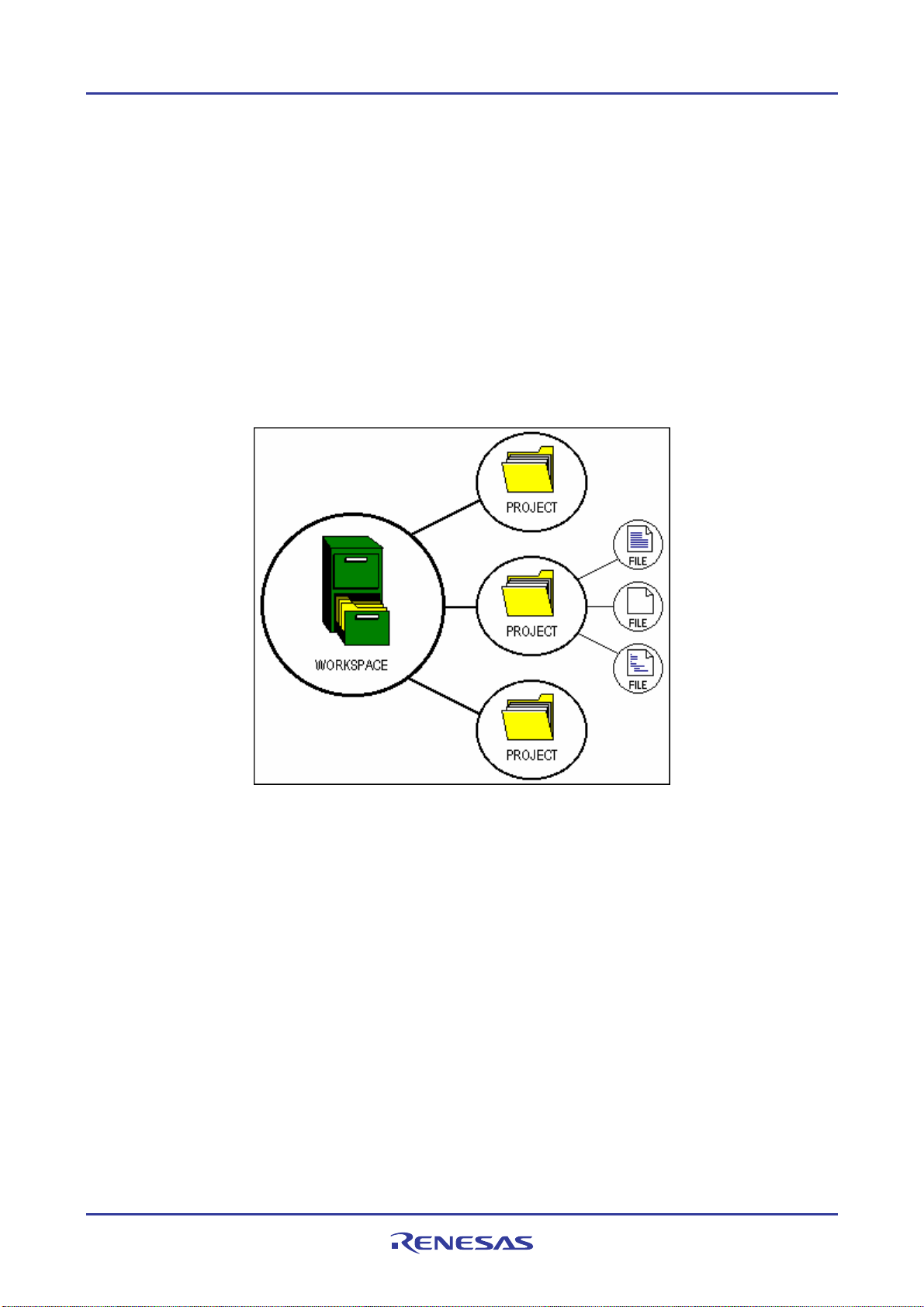
High-performance Embedded Workshop 1. Overview
1. Overview
The functions for High-performance Embedded Workshop version 4.05.00 are explained in this manual.
This chapter describes the fundamental concepts of the High-performance Embedded Workshop.
1.1 Workspaces, projects and files
Just as a word processor allows you to create and modify documents, the High-performance Embedded Workshop
allows you to create and modify workspaces.
A workspace can be thought of as a container of projects and, similarly, a project can be though t of as a container of
project files. Thus, each workspace contains one or more projects and each project contains one or more files. The
figure below illustrates this graphically:
Workspaces allow you to group related projects together. For example, you may have an application that needs to be
built for different processors, or you may be developing an application and lib rary at the same time. Projects can also be
linked hierarchically within a workspace, which means that when one project is built all of its ‘child’ projects are built
first.
However, workspaces on their own are not very useful – we need to add a project to a workspace and then add files to
that project before we can actually do anything.
1.2 Main window
There are three main windows: the workspace window, the editor window and the output window. The workspace
window shows the projects and files that are currently in the workspace; the editor window provides file viewing and
editing facilities; and the output window shows the results of a various processes (e.g. build, version control commands
and so on).
REJ10J1837-0100 Rev.1.00 Nov. 16, 2008
1
Page 17
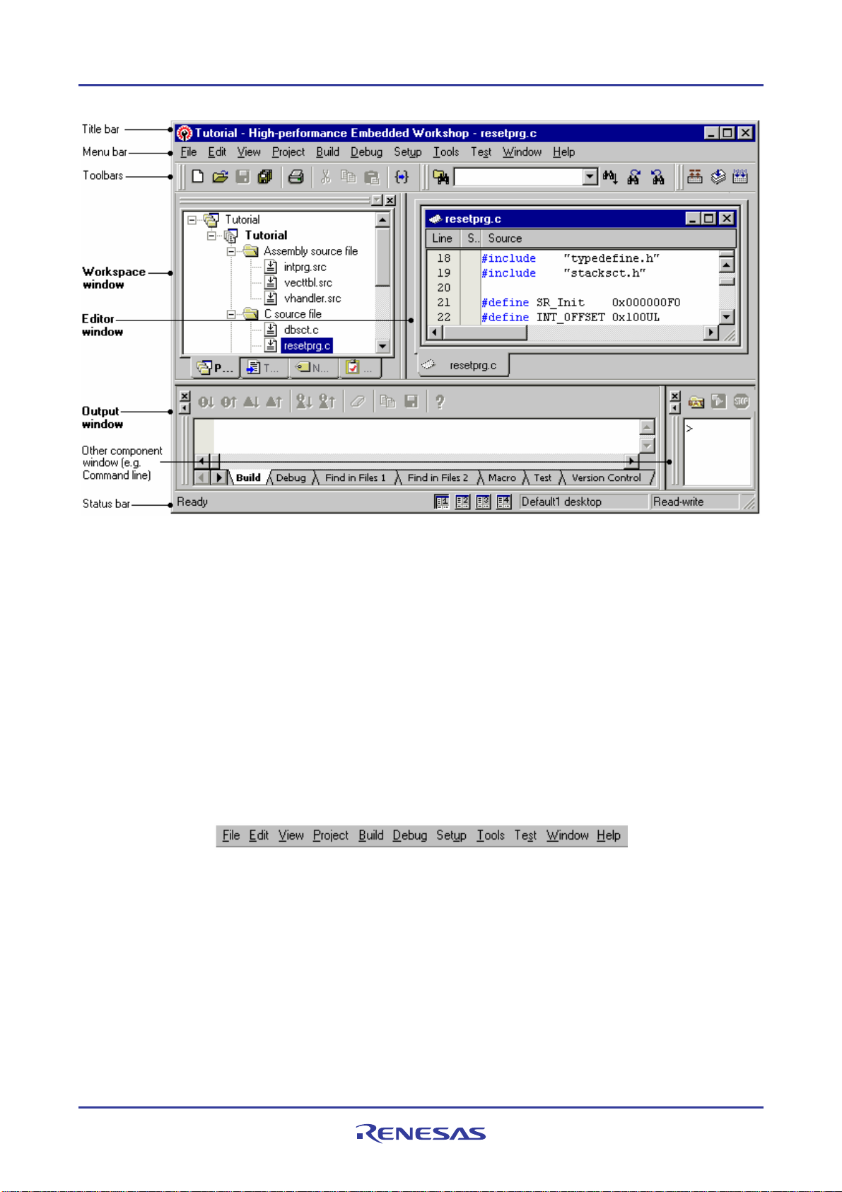
High-performance Embedded Workshop 1. Overview
1.2.1 Title bar
Th
e title bar displays the name of current activate project and file. It also contains the standard Minimize, Maximize
and Close buttons. Click the Minimize button to minimize the High-performance Embedded Workshop on the
Windows® task bar. Click the Maximize button to force High-performance Embedded Workshop to fill the screen.
Click the Close button to close the High-performance Embedded Workshop (this has the same effect as selecting [File -
> Exit], or pressing ALT+F4).
1.2.2 Menu bar
e menu bar initially contains eleven menus: File, Edit, View, Project, Build *, Debug, Setup, Tools, Test, Window
Th
and Help. All of the menu options are grouped logically under these headings. For instance, if you want to open a file
then the File menu is where you will find the right menu option; if you want to set-up a tool then the Tools menu is the
correct selection.
Note:
*. If you use a debug-only project "Debugger only - xxxxxx" created by High-performance Embedded Workshop
V.4.01 or a later version, the Build menu will not be displayed by default. The Build menu is displayed, however, if
the debug-only project "Debugger only - xxxxxx" has bee n created by Hi g h- performance Embedded Workshop
earlier than V.4.01.
REJ10J1837-0100 Rev.1.00 Nov. 16, 2008
2
Page 18
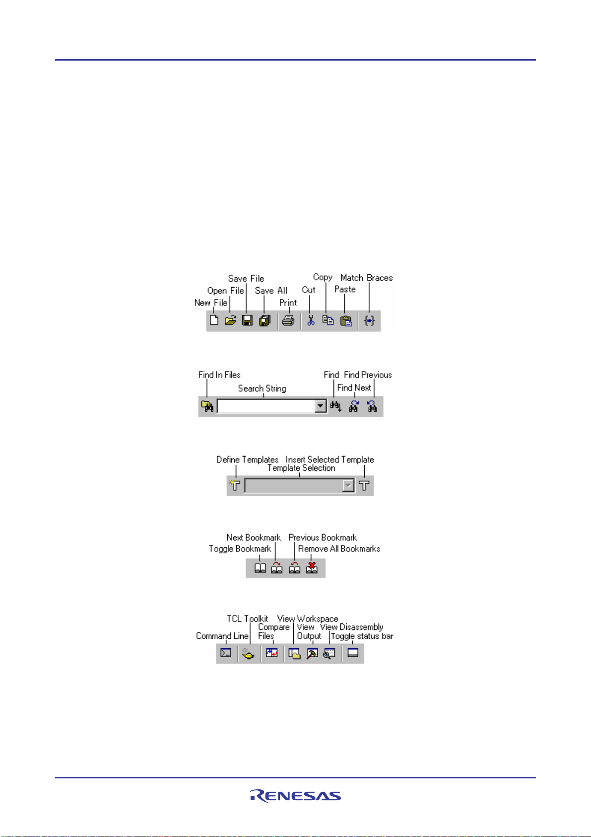
High-performance Embedded Workshop 1. Overview
1.2.3 Toolbars
The toolbars provide a shortcut to the options that you will use the most often. There are twelve default toolbars:
Editor, Search, Templates, Bookmarks, Default Window, Standard, Version Control, Map, Macros, Debug,
Debug Run, and System Tools (as shown in the figures below).
With the default session, the High-performance Embedded Workshop does not initially display buttons of Version
Control and peripheral functions on the toolbar.
If you use a debug-only project “Debugger only – xxxxxx” created by High-performance Embedd ed Wor kshop V.4.01
or a later version, Editor, Search, Templates, Bookmarks, Default Window, and Standard will not be displayed by
default.
Toolbars can be created, modified and removed via [Tools -> Customize] (see section 6.1, Customizing the toolbars,
for further information).
Editor toolbar
Search toolbar
Templates toolbar
Bookmarks toolbar
Default Window toolbar
REJ10J1837-0100 Rev.1.00 Nov. 16, 2008
3
Page 19
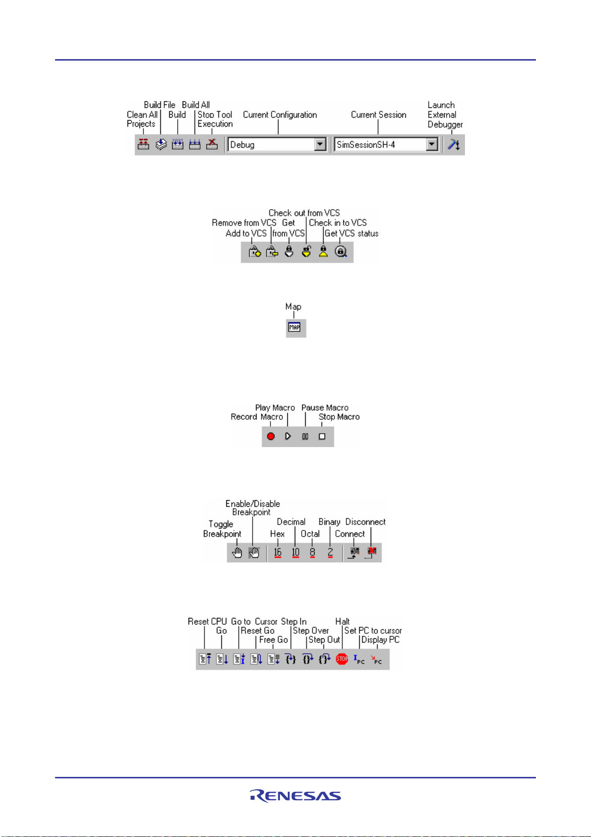
High-performance Embedded Workshop 1. Overview
Standard toolbar
Version Control toolbar
This toolbar is only available when a version control tool is being used in the current project.
Map toolbar
Macros toolbar
You can add a customized button, to which a created macro has been assigned, on the right to the standard macro
buttons on the toolbar as shown below.
Debug toolbar
This toolbar is only available when a session is being used which has a target attached.
Debug Run toolbar
This toolbar is only available when a session is being used which has a target attached.
REJ10J1837-0100 Rev.1.00 Nov. 16, 2008
4
Page 20
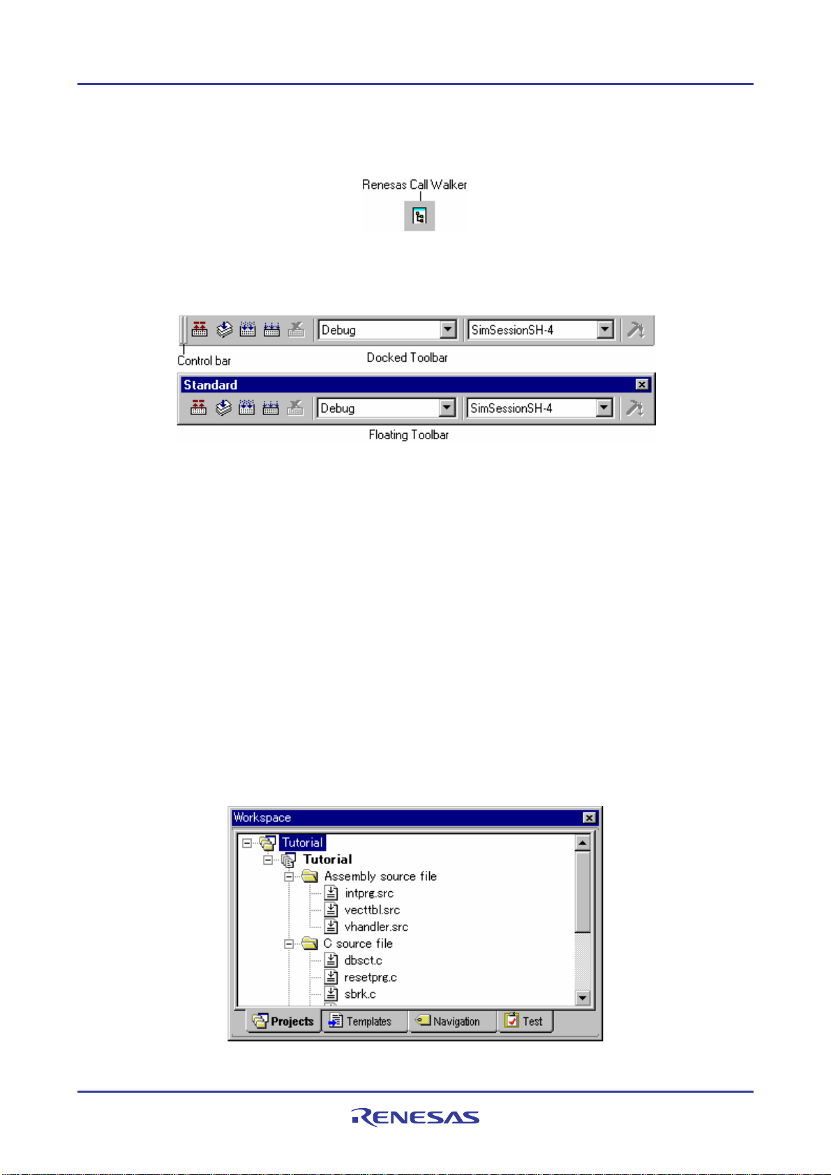
High-performance Embedded Workshop 1. Overview
System Tools toolbar
You can add an external tool button, to which an external tool menu has been assigned, on the right to the system tool
button on the toolbar as shown below.
When the Standard toolbar is docked, it has a Control bar as shown in the figure below. If you want to move the docked
Standard toolbar, click and drag its Control bar to the new location. The figure below shows the Standard toolbar when
it is docked and also when it is floating.
To dock a toolbar
Select one of the following operations:
• Double-click on the title bar of a floating toolbar, OR
• Drag the title bar of a floating toolbar and draw it toward an edge of a docked window, menu bar, toolbar or
the High-performance Embedded Workshop main frame, on whose edge you would like to dock the window,
until the shape of the floating bar changes.
To float a toolbar
Select one of the following operations:
• Double-click on the control bar of a docked toolbar, OR
• Drag the control bar of a docked toolbar and draw it away from the edge of the High-performance Embedded
Workshop main frame and from an edge of the other docked windows, menu bar or toolbars.
1.2.4 Workspace window
The Wor
kspace window has four tabs (Projects, Templates, Navigation, and Test).
REJ10J1837-0100 Rev.1.00 Nov. 16, 2008
5
Page 21
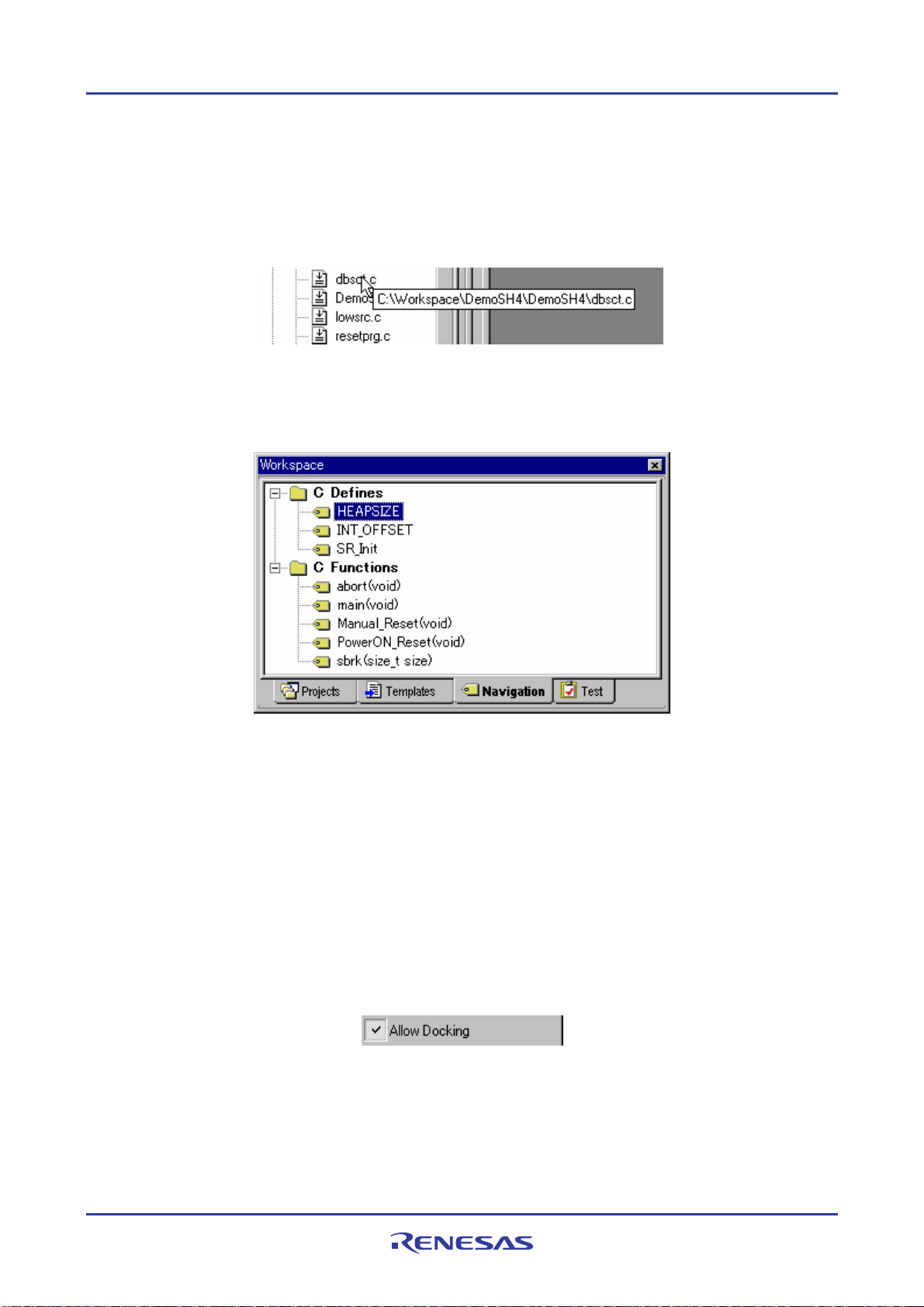
High-performance Embedded Workshop 1. Overview
• Projects tab
Allows you to show the current workspace, projects and files. You can quickly open any project file or dependent file
by double-clicking on its icon. See section 2.2, Configuring the Projects tab of the Workspace window, for more
information on the Projects tab.
If you hover the mouse pointer over a file in the Projects tab then the file’s full path will be displayed in a tool tip.
• Templates tab
Allows you to display template settings. See section 4.11, Templates, for more information about a template.
• Navigation tab
Allows you to provide jumps to various textual constructs within your project’s files. What is actually displayed within
the Navigation tab depends upon what components are currently installed. The figure above shows C macro definitions
(C Defines) and C functions (C Functions) conforming to the ANSI standard. See Chapter 12, Navigation Facilities, for
more information about navigation.
• Test tab
Allows you to setup or view test suites as part of the test-support facility. See Chapter 16, Using the Test Support
Facility, for more information about the test-support facility.
To allow the Workspace window or the Output window docking
Right-click anywhere inside the Workspace window or the Output window. Then a pop-up menu will be displayed.
If the Allow Docking option is checked, docking is allowed. Otherwise, docking is not allowed. Select the Allow
Docking option to check or un-check it.
REJ10J1837-0100 Rev.1.00 Nov. 16, 2008
6
Page 22
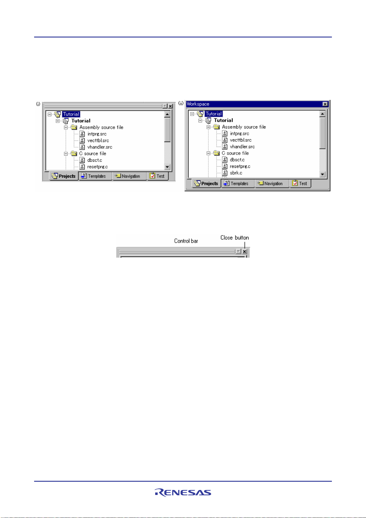
High-performance Embedded Workshop 1. Overview
When the Allow Docking option is checked, you can dock a window, toolbar or menu bar to the edge of the Highperformance Embedded Workshop main window or to the edge of another docked window. You can also float them
‘above’ the other High-performance Embedded Workshop windows or outside the High-per fo rmance Embedded
Workshop main window. Figure (i) below shows a docked “Workspace” window, and figure (ii) below shows a floating
“Workspace” window.
When the Workspace window or the Output window is docked, it has a control bar as shown below.
If you want to move a docked window, click and drag its control bar to the new location.
To dock the Workspace window or the Output window
1. Ensure that the Allow Docking option is checked on the window’s pop-up menu.
2. Select one of the following operations:
• Double-click on the title bar of a floating window, OR
• Drag the title bar of a floating window and draw it toward an edge of a docked window, menu bar or
toolbar, or the High-performance Embedded Workshop main frame, on whose edge you would like to dock
the windows.
To float the Workspace window or the Output window
1. Ensure that the Allow Docking option is checked on the window’s pop-up menu.
2. Select one of the following operations:
• Double-click on the control bar of a docked window, OR
• Drag the control bar of a docked window and draw it away from the edge of the High-performance
Embedded Workshop main frame and from an edge of the other docked windows, menu bar or toolbar.
• Drag the control bar of a docked window while pressing the "CTRL" key.
REJ10J1837-0100 Rev.1.00 Nov. 16, 2008
7
Page 23
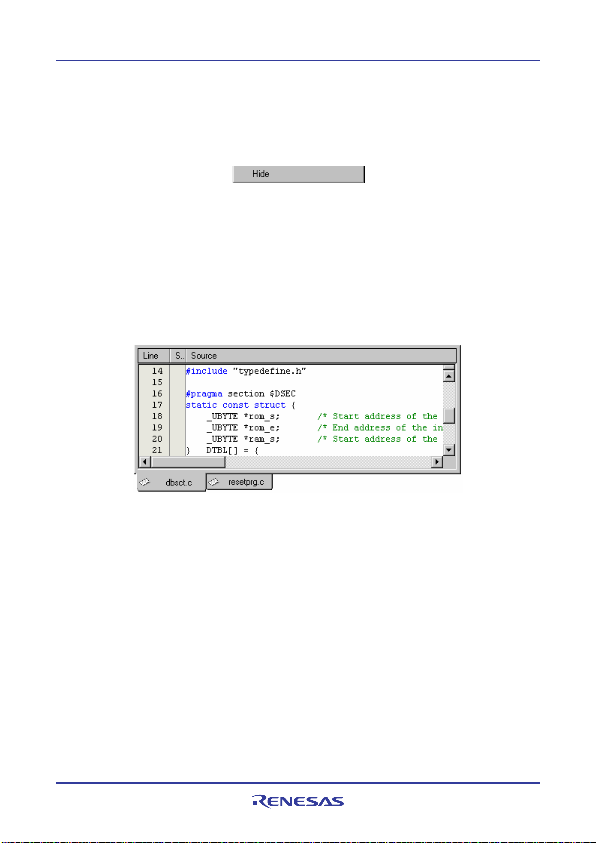
High-performance Embedded Workshop 1. Overview
To hide the Workspace window or the Output window
Select one of the following operations:
• Click on the close button, which is located in the top right corner of the window, OR
• Right-click anywhere inside a floating window and select the Hide option on the pop-up menu.
To show the Workspace window or the Output window
Select [View -> Workspace] or [View -> Output] respectively.
1.2.5 Editor window
e editor window is where you will work with the files of your project. The High-performance Embedded Workshop
Th
allows you to have many files open at one time, to switch between them, to arrange them and to edit them in whichever
order you want to. By default, the editor window is displayed in a notebook style. This means that each file has a
separate tab associated with it to aid in navigating between files (see the figure below).
The editor contains a gutter (column) on the left-hand side of the window. The standard column allows the user to
configure the position of bookmarks and software breakpoints (*) quickly and easily. If you are unsure what purpose a
column has or what the information it is displaying is if you place the mouse pointer over the column a tool tip (pop-up
window) is displayed showing its identity.
The editor window can be customized via the Format Views dialog box, which can be invoked via [Setup -> Format
Views]. This dialog box allows you to configure fonts, colors, tabs and so on for the editor window. It also allows the
user to change the look of other views, which have been installed by High-performance Embedded Workshop. If you
would prefer to use your favorite editor rather than th e High-p erformance Embedd ed Workshop internal editor then
specify your alternative in the Options dialog box, which can be invoked via [Setup -> Options]. For furthe r details on
how to use the editor, see Chapter 4, Using the Editor.
Note:
*. Allows you to set software breakpoints only when the debugger is connected to the session.
REJ10J1837-0100 Rev.1.00 Nov. 16, 2008
8
Page 24
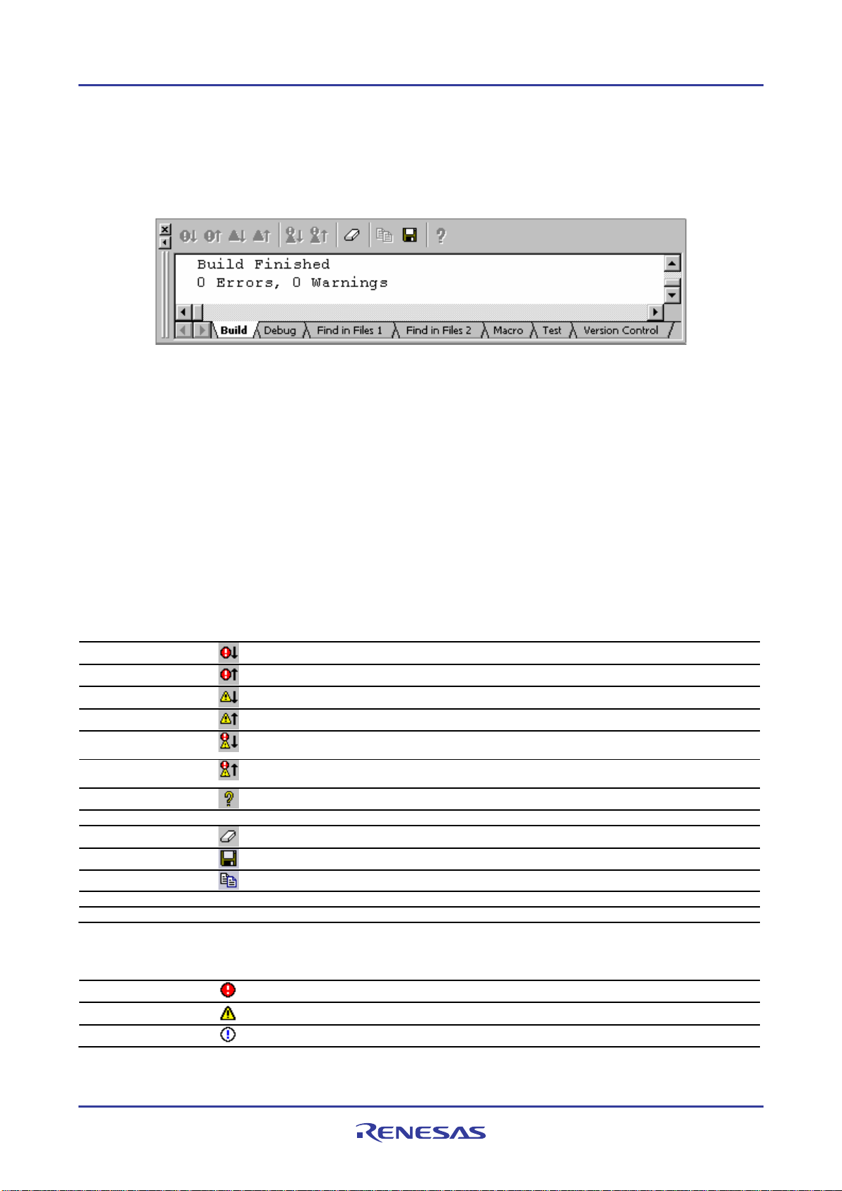
High-performance Embedded Workshop 1. Overview
1.2.6 Output window
The Output window, by default, has seven tabs (Build, Debug, Find in Files 1, Find in Files 2, Macro, Test, and
Version Control) on display.
Build tab
The Build tab shows the output from any build process (e.g. compiler, assembler and so on). If an error is encountered
in a source file, an icon and the error message will be displayed in the Build tab, along with the source file name and
line number.
If you click on a toolbar button or pop-up menu option associated with display of error messages, the line of the error
message will be highlighted and the editor will show the source code of that line (if the line has any source code).
Double-clicking the line of an error message will also show the source code in the editor.
When you attempt an operation to display an error or warning, the status bar shows this error or warning message.
Right-clicking displays a pop-up menu containing available options.
A basic operation is allocated to the toolbar.
The functions of Toolbar display and Customize toolbar are also included in the pop-up menu displayed by right-
clicking the toolbar area.
Pop-up Menu Option Toolbar Button Function
-
-
-
Display next
Error/Warning/Info
Display previous
Error/Warning/Info
Help
Go to Error/Warning/Info - Goes to the associated source line.
Clear Window
Save
Copy
Toolbar display - Shows or hides the toolbar.
Customize toolbar - Customizes toolbar buttons.
Highlights the next occurrence of error and shows the source code in the editor.
Highlights the previous occurrence of error and shows the source code in the editor.
Highlights the next occurrence of warning and shows the source code in the editor.
Highlights the previous occurrence of warning and shows the source code in the editor.
Displays the editor that generated the next build error or warning.
Displays the editor that generated the previous build error or warning.
Shows the help information about the line.
Clears the contents of the window.
Saves the contents of the window into a text file.
Copies the selected contents onto the Windows® clipboard.
The Build tab also shows an icon corresponding to the error message output by build execution.
Icon Name Icon Error Message Level
Build Error
Build Warning
Information
Error
Warning
Information
REJ10J1837-0100 Rev.1.00 Nov. 16, 2008
9
Page 25
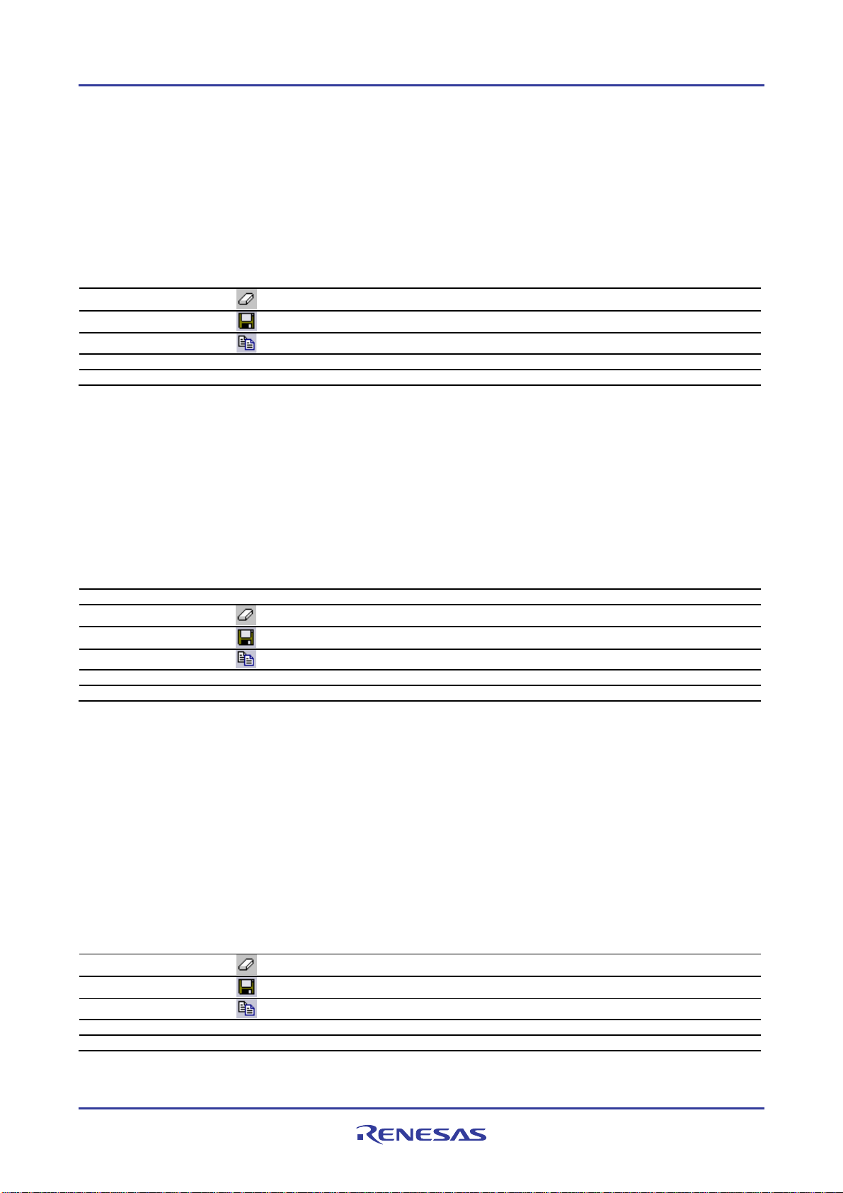
High-performance Embedded Workshop 1. Overview
Debug tab
Shows the output from any debugger process. Any debug component that needs to display information will send its
output to this window.
Right-clicking displays a pop-up menu containing available options.
A basic operation is allocated to the toolbar.
The functions of Toolbar display and Customize toolbar are also included in the pop-up menu displayed by right-
clicking the toolbar area.
Pop-up Menu Option Toolbar Button Function
Clear Window
Save
Copy
Toolbar display - Shows or hides the toolbar.
Customize toolbar - Customizes toolbar buttons.
Clears the contents of the window.
Saves the contents of the window into a text file.
Copies the selected contents onto the Windows® clipboard.
Find in Files 1 and Find in Files 2 tab
Shows the results of the last Find in Files action. To activate find in files, select [Edit -> Find In Files], or click the
Find In Files toolbar button. For further details on using Find in Files, see section 4.4.2, Finding text in multiple files.
Right-clicking displays a pop-up menu containing available options.
A basic operation is allocated to the toolbar.
The functions of Toolbar display and Customize toolbar are also included in the pop-up menu displayed by right-
clicking the toolbar area.
Pop-up Menu Option Toolbar Button Function
Go to Occurrence - Go to the associated source line.
Clear Window
Save
Copy
Toolbar display - Shows or hides the toolbar.
Customize toolbar - Customizes toolbar buttons.
Clears the contents of the window.
Saves the contents of the window into a text file.
Copies the selected contents onto the Windows® clipboard.
Macro tab
Shows the current records of macros (macro-recording support facility). You can view information such as Highperformance Embedded Workshop command-line commands recorded into a High-performance Embedded Workshop
macro file from execution of [Tools -> Macro Recording] to [Tools -> Stop Macro]. It is also possible to view this
information while recording. For details on the macro-recording support facility, see Chapter 15, Using the MacroRecording Support Facility.
Right-clicking displays a pop-up menu containing available options.
A basic operation is allocated to the toolbar.
The functions of Toolbar display and Customize toolbar are also included in the pop-up menu displayed by right-
clicking the toolbar area.
Pop-up Menu Option Toolbar Button Function
Clear Window
Save
Copy
Toolbar display - Shows or hides the toolbar.
Customize toolbar - Customizes toolbar buttons.
Clears the contents of the window.
Saves the contents of the window into a text file.
Copies the selected contents onto the Windows® clipboard.
REJ10J1837-0100 Rev.1.00 Nov. 16, 2008
10
Page 26
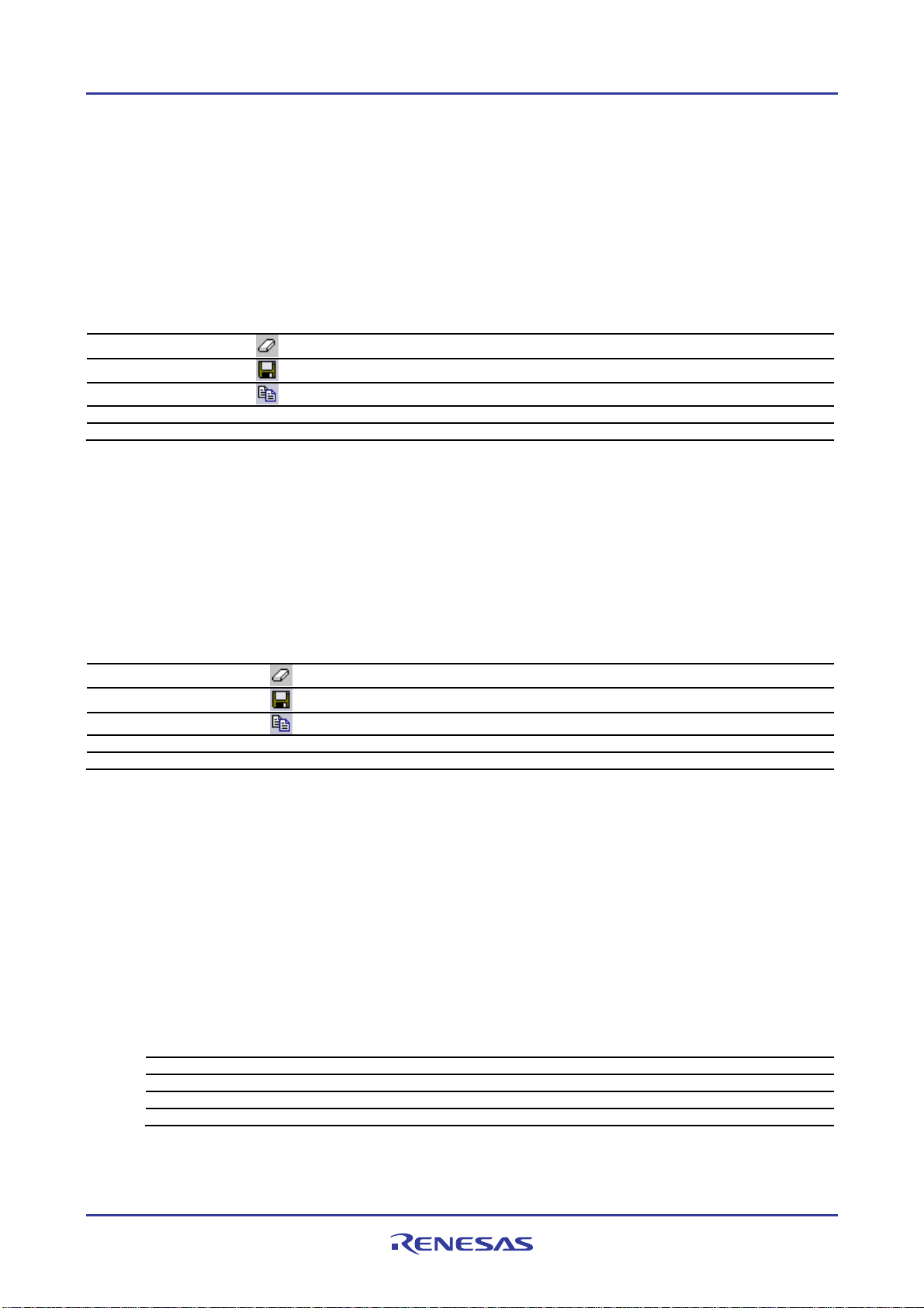
High-performance Embedded Workshop 1. Overview
Test tab
Shows the results and progress of the current test execution (test support facility). The test execution progress shows
the current test being executed and the number of tests remaining. If errors occur then these are displayed in this
window. For details on the test-support facility, see Chapter 16, Using the Test Support Facility.
Right-clicking displays a pop-up menu containing available options.
A basic operation is allocated to the toolbar.
The functions of Toolbar display and Customize toolbar are also included in the pop-up menu displayed by right-
clicking the toolbar area.
Pop-up Menu Option Toolbar Button Function
Clear Window
Save
Copy
Toolbar display - Shows or hides the toolbar.
Customize toolbar - Customizes toolbar buttons.
Clears the contents of the window.
Saves the contents of the window into a text file.
Copies the selected contents onto the Windows® clipboard.
Version Control tab
Shows the results of version control actions. The tab is only displayed if a version control system is in use. For further
details on version control, see Chapter 7, Version Control.
Right-clicking displays a pop-up menu containing available options.
A basic operation is allocated to the toolbar.
The functions of Toolbar display and Customize toolbar are also included in the pop-up menu displayed by right-
clicking the toolbar area.
Pop-up Menu Option Toolbar Button Function
Clear Window
Save
Copy
Toolbar display - Shows or hides the toolbar.
Customize toolbar - Customizes toolbar buttons.
Clears the contents of the window.
Saves the contents of the window into a text file.
Copies the selected contents onto the Windows® clipboard.
Press the "SHIFT+ESC" key, and the Output window closes.
The color of text or background and font shown in the Output window can be customized in the same manner as in
other windows. You can also customize the Build tab of the Output window so that the texts in the lines of error
messages will be highlighted in a color different from that of the texts in other lines.
To customize the current colors
1. Select [Setup -> Format Views] to open the Format Views dialog box.
2. Select the Output item from the tree in the left-hand section of the dialog box and expand it.
3. Select the category for which you wish to change the color from the table below.
Category Foreground Color of the
Color Tab (Default)
Text SYSTEM SYSTEM All tabs All
Build Error Text Black White Build Error
Build Warning Text Black White Build Warning
Information Text Black White Build Information
Background Color of the
Color Tab (Default)
Tab(s) to be
Applied
Type of Output to
be Applied
4. Change the selection in the Foreground and Background lists of the Color tab.
5. Click the OK button.
REJ10J1837-0100 Rev.1.00 Nov. 16, 2008
11
Page 27
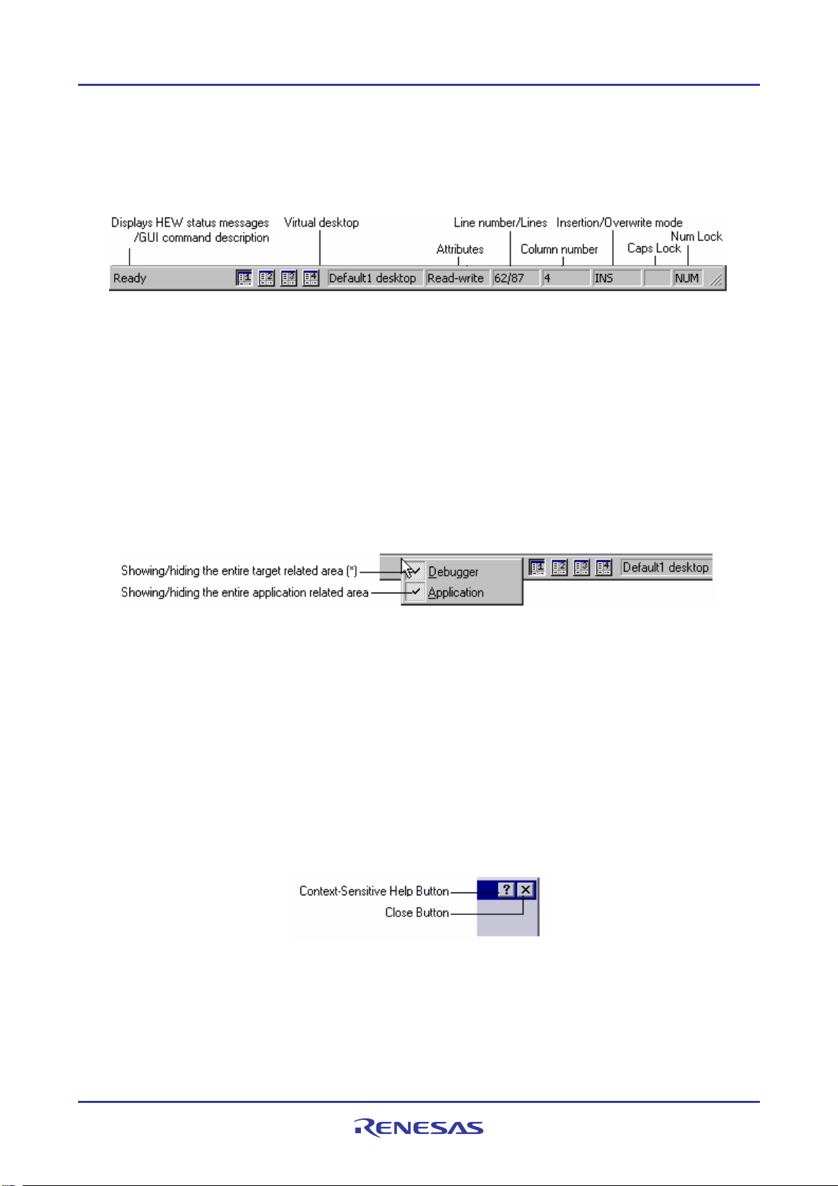
High-performance Embedded Workshop 1. Overview
1.2.7 Status bar
The status bar displays various information about the current state of the High-performance Embedded Workshop. The
figure below shows the status bar.
The customizable status bar feature allows the user to customize the display of the status bar area and its contents. The
status bar will also now show target-related information where required by the specific target being used.
The bottom section of the status bar area shows the standard application-based information as in previous version of
High-performance Embedded Workshop. Abo ve this is the target-related information. The information displayed here is
completely target dependant, and in some cases there may not be any target-related information to display.
The status bar can be switched on and off via [View -> Status Bar]. When any part of the status bar area is visible, this
main menu option will completely switch off the status bar area. When the status bar is completely hidden, this main
menu option will switch on the application-based section of the status bar.
The status bar can also be switched off via the status bar pop-up menu. The pop-up menu allows individual status bar
items to be toggled on and off; including both application and target related areas as well as individual items on each.
The pop-up menu can be displayed by selecting the right-mouse button over the status bar area.
Note:
*. The entire target related area of the status bar is hidden depending on the target being used.
All target related status bar items are switched off, the entire target related area of the status bar will be hidden by
default. This can be re-shown by switching on one or more target related individual status bar items.
1.3 Help system
The Help menu is the rightmost menu on the High-performance Embedded Workshop menu bar. It contains the Help
Topics menu option, which, when selected, takes you to the main High-performance Embedded Workshop help
window.
To obtain help on specific dialogs click the context-sensitive help button, which is located in the top right-hand corner
of each dialog (as shown in the figure below).
When this is clicked, the mouse pointer will change to a pointer with a question mark above it. Whilst the mouse
pointer is in this state, click on the part of the dialog that you require assistance on. Alternatively, select the control for
which you require help, and press the F1 key.
REJ10J1837-0100 Rev.1.00 Nov. 16, 2008
12
Page 28
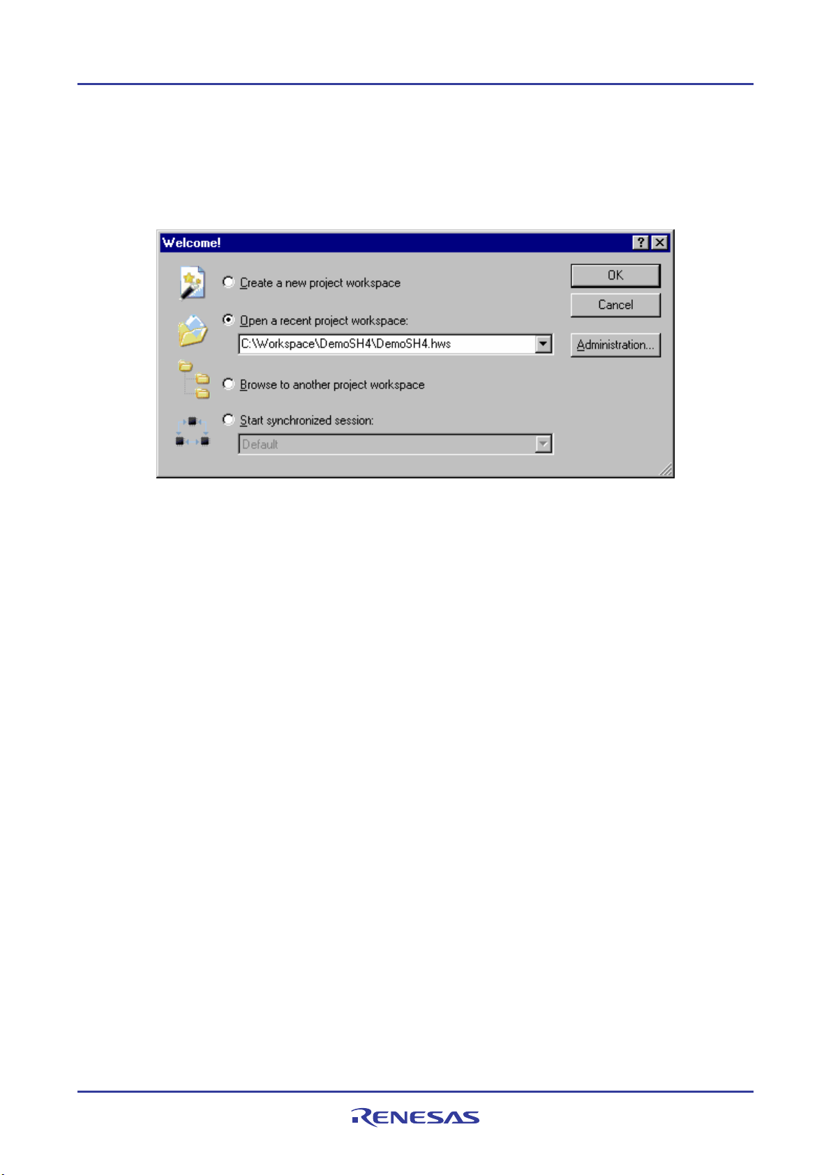
High-performance Embedded Workshop 1. Overview
1.4 Launching the High-performance Embedded Workshop
To initiate the High-performance Embedded Workshop, open the Start menu of Windows®, select Programs, select
Renesas, select High-performance Embedded Workshop, and then select the shortcut of the High-performance
Embedded Workshop. The Welcome! dialog box will be displayed after the start-up screen.
If you have recently used a workspace, Open a recent project workspace is selected by default. Otherwise Create a
new project workspace is selected.
To create a new workspace select the Create a new project workspace button and click the OK button.
To open one of the recent project workspaces select the Open a recent project workspace button, select a workspace
from the drop-down list, and click the OK button. The Recent Workspace list displays the same content as that seen in
the workspace most recently used File list. This list also appears on the File menu.
To open a workspace by specifying a workspace file (".HWS" file), select the Browse to another project workspace
button, and click the OK button.
To open the Synchronized Debug dialog box select the Start synchronized session button and select a configuration
from the drop-down list and click the OK button. This item is only available when a synchronized debugging facility
has been used.
To register or un-register a tool from the High-performance Embedded Workshop, click the Administration button.
Click the Cancel button to use the High-performance Embedded Workshop without opening a workspace.
If you do not wish to open the Welcome! dialog box next time you launch the High-performance Embedded Workshop,
select [Setup -> Options]. The Options dialog box opens. Remove a tick mark from the Display Welcome Dialog
checkbox in the Confirmation tab.
If you do not wish to view the start-up screen when launching the High-performance Embedded Workshop, remove a
tick mark from the Display Splash Screen checkbox in the Confirmation tab of the Options dialog box.
1.5 Creating a new workspace
To create a new workspace
1. Select the Create a new project workspace option from the Welcome! dialog box and click the OK button or
select [File -> New Workspace]. The New Project Workspace dialog box will be displayed.
2. Enter the name of the new workspace into the Workspace Name field. This can be up to 32 characters in
length and contain letters, numbers, and the underscore character. Especially, do not use a minus sign, or a
space. As you enter the workspace name, the High-performance Embedded Workshop will add a sub-directory
and Project Name for you automatically. This can be changed if desired. This allows the workspace and
REJ10J1837-0100 Rev.1.00 Nov. 16, 2008
13
Page 29
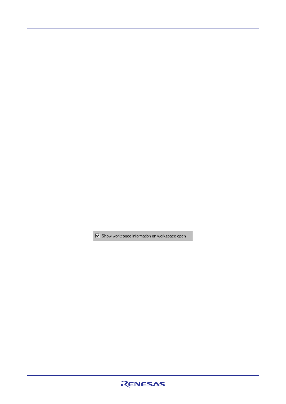
High-performance Embedded Workshop 1. Overview
project name to be different. To select the directory in which you would like to create the workspace, use the
Browse button or type the directory into the Directory field manually.
3. Select the CPU family and Tool chain upon which you would like to base the workspace.
4. When a new workspace is created, the High-performance Embedded Workshop will also automatically create
a project with the name specified in the Project Name field and place it inside the new workspace. The
project types list displays all of the available project types (e.g. Application, Library etc.). Select the type of
project that you want to create from this list. The project types displayed will be all valid types for the current
pair of CPU family and Tool chain. The project types are classified in three classes: toolchain-only, debugonly (Debugger only - xxxxxx), and full project generator that configures both the debugger and toolchain
aspect of the High-performance Embedded Workshop.
5. Click the OK button to create the new workspace and project. This then launches the wizard you have selected
to guide you through the creation process.
Note:
It is not possible to create a workspace if one already exists in the same directory.
1.6 Opening a workspace
To open a workspace
1. Select Browse to another project workspace option from the Welcome! dialog box and click the OK button
or select [File -> Open Workspace]. The Open Workspace dialog box will be displayed.
2. Select the workspace file (".HWS" file) that you want to open.
3. Click the Select button to open the workspace. If the High-performance Embedded Workshop is set up to
display information when a workspace is opened, the Workspace Properties dialog box will be displayed.
Otherwise, the workspace will be opened.
Note that whether the Workspace Properties dialog box is shown depends on the setting of either the Show
workspace information on workspace open check box in the Workspace Properties dial og bo x o r the
Display workspace information dialog on opening workspace check box on the Workspace tab of the Options
dialog box. The Options dialog box can be invoked via [Setup -> Option s]. Click the OK button in the
Workspace Properties dialog box to open the workspace. Click the Cancel button to stop opening the
workspace.
The High-performance Embedded Workshop keeps track of the last workspaces that you have opened and adds them to
the File menu under the Recent Workspaces submenu. This gives you a shortcut to opening workspaces, which you
have used recently.
To open a recently used workspace
Select Open a recent project workspace in the Welcome! dialog box, select the name of the workspace from the
drop-down list, and then click the OK button.
Another way is to select [File -> Recent Workspaces], and then from this submenu select the name of the workspace.
Note:
The High-performance Embedded Workshop only permits one workspace to be open at a time. Consequently, if you
attempt to open a second workspace, the first will be closed before the new one is opened.
REJ10J1837-0100 Rev.1.00 Nov. 16, 2008
14
Page 30
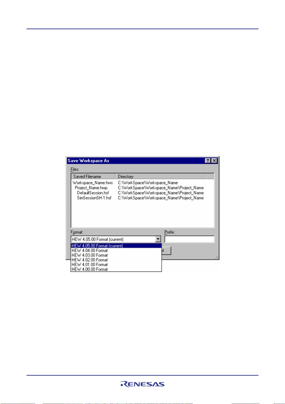
High-performance Embedded Workshop 1. Overview
1.7 Using old workspaces
The High-performance Embedded Workshop can open any workspace that was created on a previous version of the
High-performance Embedded Workshop. This should be automatically upgraded when the workspace is opened. A
back-up version of the initial workspace or project file must be saved in the current directory of the file that has been
upgraded.
1.8 Saving a workspace
The amount of information on workspaces (and projects) to be saved increases as the High-performance Embedded
Workshop is upgraded. Thus the format in which workspaces can be saved is slightly different depending on the version
of the High-performance Embedded Worksh op.
To save a High-performance Embedded Workshop workspace in the current version's format, select [File -> Save
Workspace].
To save the workspace in a previous version's format, select [File -> Save Workspace As]. If the current workspace
has changed since it was last changed, you will be prompted to save it (to the current file and version). The Save
Workspace As dialog box will then be launched:
This contains a list of all the files currently associated with the workspace, a drop-list control containing a list of
available versions (the current version is selected by default) and an edit control where you can enter a short prefix that
will be used to change the name of all the associated files. When the prefix is changed, the File list is updated to display
the new names.
For example, to save the workspace in a format that can be loaded from High-performance Embedded
Workshop V.4.02.00
1. Set the Format drop-down list: HEW 4.02.00 Format
2. Enter Prefix: 402_
3. Click OK.
REJ10J1837-0100 Rev.1.00 Nov. 16, 2008
15
Page 31

High-performance Embedded Workshop 1. Overview
A copy of the workspace will be saved into the current directory (so all the source files, etc. will remain in use) but with
the entered prefix, e.g.:
C:\Workspace\Workspace_Name\402_Workspace_Name.hws
C:\Workspace\Workspace_Name\Projet_Name\402_Projet_Name.hwp
C:\Workspace\Workspace_Name\Projet_Name\402_DefaultSession.hsf
C:\Workspace\Workspace_Name\Projet_Name\402_SimSessionSH-1.hsf
Note that the current workspace (in this example 4.05.00) remains loaded as the working copy.
1.9 Closing a workspace
To close a High-performance Embedded Workshop workspace, select the [File -> Close Workspace] menu option. If
there are any outstanding changes to the workspace or any of its projects you will be requested whether or not you wish
to save them.
1.10 Exiting the High-performance Embedded Workshop
The High-performance Embedded Workshop can be exited by selecting [File -> Exit], pressing ALT+F4, or by
selecting the close option from the system menu (which is opened by clicking the icon at the upper-left corner of the
High-performance Embedded Workshop title bar).
1.11 Component system overview
The High-performance Embedded Workshop allows the user to extend the High-performance Embedded Workshop
functionality by adding additional components to the system. This is achieved by registering the component in the
Tools Administration dialog box. These components can add windows, menus and toolbars to the High-performance
Embedded Workshop system. Examples of the components are the debugger and builder components of Highperformance Embedded Workshop. The debugger component adds all of the menus and toolbars associated with the
debugger and the builder component does the same for the build functionality. The components you have registered in
the system will modify the look and feel of High-performance Embedded Workshop. In some cases you may not have
some of the menus which you can see in this manual. For instance if the builder component is not installed you will not
have the toolchain menu option in the Build menu.
1.12 Management information files of High-performance Embedded Workshop
The High-performance Embedded Workshop has the following files containing management information necessary for
its correct operation.
• A file in which application-level setting is stored
• A file in which the default positions of windows are recorded
• High-performance Embedded Workshop database files
• Component's data files *
• Keyboard shortcut layout files
• Macro information file and newly added macro files
• Custom project-type wizard files
• Syntax highlighting files
• Templates files
• Synchr oni zed debug option configuration files *
REJ10J1837-0100 Rev.1.00 Nov. 16, 2008
16
Page 32

High-performance Embedded Workshop 1. Overview
Note:
*. Support for this function depends on the debugger.
These files are specific to each user account on the host computer. When multiple versions of the High-per formance
Embedded Workshop are installed, the files specific to each High-performance Embedded Workshop are saved for each
user account.
1.13 Overview of Configurations and Sessions
The drop-down list box on the Standard toolbar shows the current configuration and session.
This example shows the configuration and session in which the Renesas SuperH Standard toolchain was selected at
creation of a project and "SH-4 Simulator" was selected as the target debugging platform.
You can switch between different configurations and sessions by selecting one in the drop-down list box.
It is also possible to add or delete configurations or sessions as necessary.
• Configuration
What is config uration?
Configurations are the build option settings (e.g., output of debug information or optimization) having their own names.
The term "configuration" can also be referred to as "build configuration".
In the figure of the Standard toolbar shown as an example, configurations "SimDebug_SH-4", "Debug", and "Release"
are available.
Configurations created by the High-performance Embedded Workshop
When a project is created after selection of the toolchain, the High-performance Embedded Workshop automatically
creates configurations "Debug" and "Release".
REJ10J1837-0100 Rev.1.00 Nov. 16, 2008
17
Page 33

High-performance Embedded Workshop 1. Overview
If you have selected a target debugging platform at creation of the project, the High-performance Embedded Workshop
creates a configuration suitable for the debugging platform. If you have selected "SH-4 Simulator" in Targets at creation
of the project, configuration "SimDebug_SH-4" is created.
Configuration names can be changed when creating a project. Directories corresponding to each of the configurations
are created under the project directory *. These directories have the names of the configurations.
REJ10J1837-0100 Rev.1.00 Nov. 16, 2008
18
Page 34
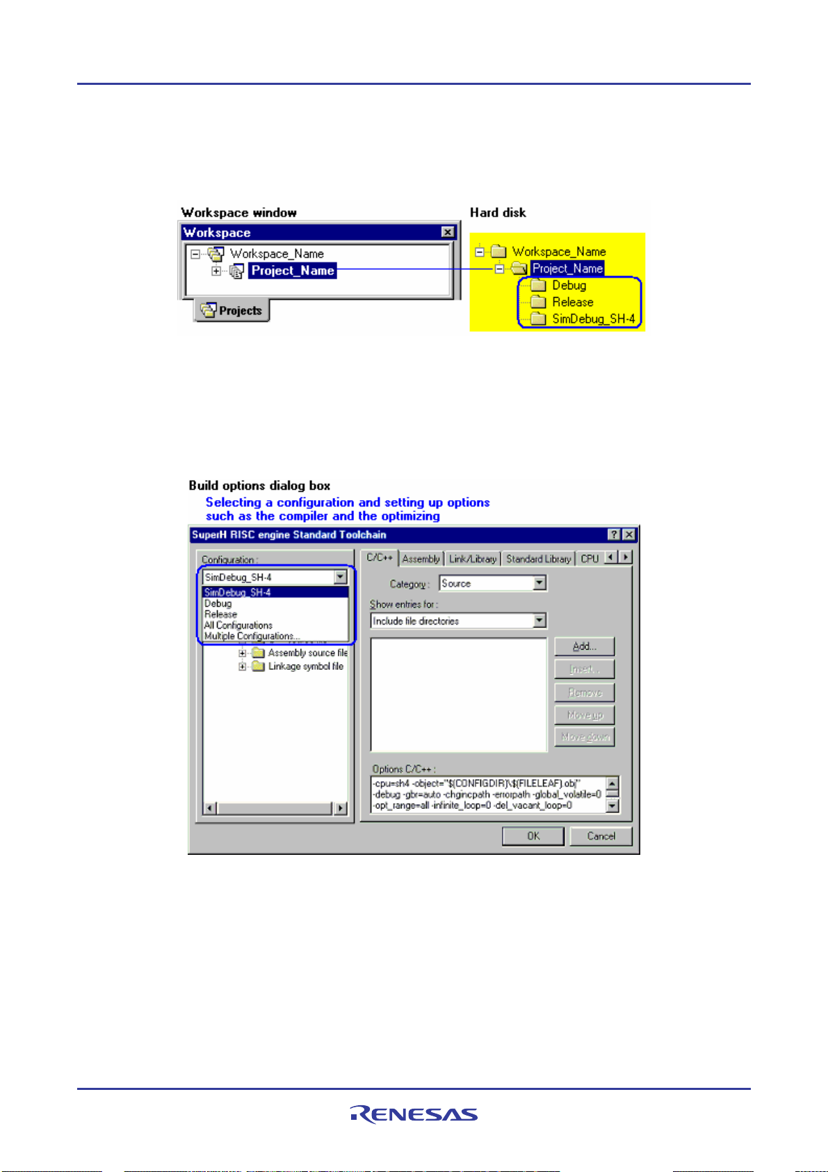
High-performance Embedded Workshop 1. Overview
Note:
*. The project directory having the project name is created under the workspace directory used for creation of a new
workspace.
How to set up build options
To set up build options kept with a configuration, select the configuration from the drop-down list box in the dialog box
for set up build option opened from the Build menu. Options such as the compiler, assembler, and optimizin g linkage
editor can be set up. The figure below shows the dialog box used for setup of build options for the Renesas SuperH
Standard toolchain.
See section 2.7, Build configurations, for more information about a configuration.
• Session
What is session?
Sessions, which have their own names, are the units to manage various settings such as High-performance Embedded
Workshop debugger options * used for debugging with connection to the debugging platform and options specific to the
debugging platform, and information on the Memory and Register windows and their positions. The term "session" can
also be referred to as "debugger session".
REJ10J1837-0100 Rev.1.00 Nov. 16, 2008
19
Page 35
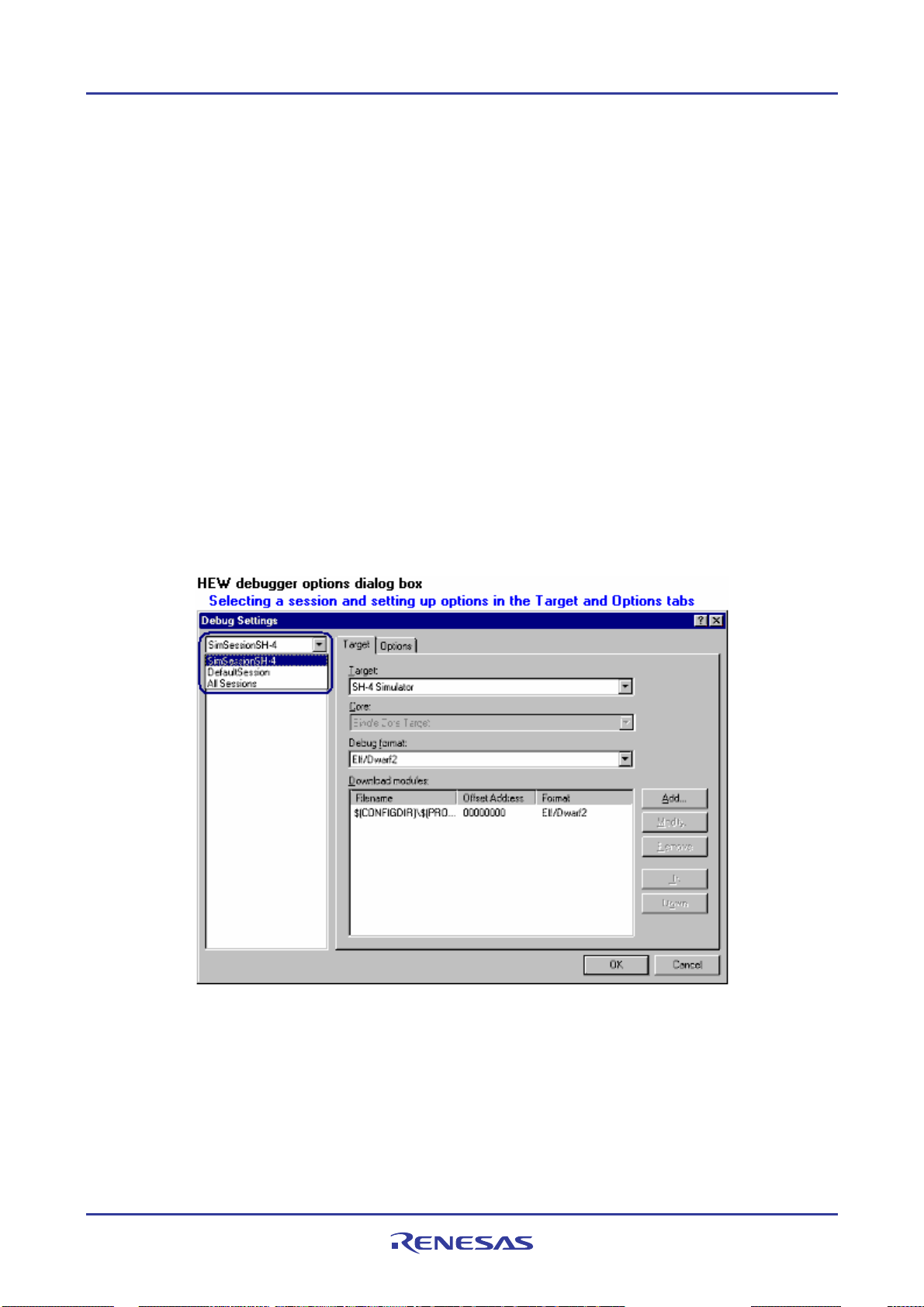
High-performance Embedded Workshop 1. Overview
In the figure of the Standard toolbar shown as an example, sessions "SimSessionSH-4" and "DefaultSession" are
available. Information on each session is saved in an individual file in the High-performance Embedded Workshop
project.
Note:
*. There are various option settings such as the debugging platform to be connected with the High-performance
Embedded Workshop, the object format for debugging, download modules, and the timing of connecting the High-
performance Embedded Workshop with the debugging platform or executing a command batch by the High-
performance Embedded Workshop.
Sessions created by the High-performance Embedded Workshop
When a project is created after selection of the toolchain, the High-performance Embedded Workshop automatically
creates session "DefaultSession". If you have selected a target debugging platform at creation of the project, a session is
automatically created for connecting the High-performance Embedded Workshop with the selected debugging platform.
For example, if you have selected "SH-4 Simulator" in "Target" at creation of a project, session "SimSessionSH-4" is
automatically created.
How to set up High-performance Embedded Workshop debugger options
To set up High-performance Embedded Workshop debugger options kept with a session, select the session from the
drop-down list box in the Debug Settings dialog box opened from the Build menu . Options can be set up in the Target
and Options tabs.
See section 17.1.6, Debugger sessions, for more information about a Debugger sessions.
REJ10J1837-0100 Rev.1.00 Nov. 16, 2008
20
Page 36
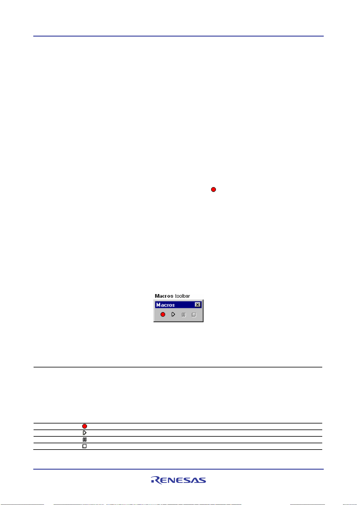
High-performance Embedded Workshop 1. Overview
1.14 Overview of Macro-Recording Support facility and Test Support facility
When coding is finished, the program must be tested. If a problem is found in testing, you will need to correct the
problem and re-test the program. Testing takes a significant number of steps in development of programs.
To ease the process of testing, the High-performance Embedded Works ho p pr o vides the macro-recording support and
test support facilities.
• Macro-recording support facility
The macro-recording support facility allows you to record operations, which are associated with the High-performance
Embedded Workshop system applications *1, build *2, and debugging *3, as High-performance Embedded Workshop
command-line commands or to execute these recorded commands.
Files to record the operations (High-performance Embedded Workshop macro files) are command line batch files that
have “hdc” as the extension and can be modified. These files are stored in the “Macros” folder within the Highperformance Embedded Workshop management information folder under the application data folder for each user
profile. By default, the file Default.hdc is created.
Note, however, that High-performance Embedded Workshop is not capable of recording all operations in the Highperformance Embedded Workshop system corresponding to the High-performance Embedded Workshop command-line
commands. For the operations that can be recorded, a macro record icon (
column of the menu list. This indicates that this operation can be recorded into a High-performance Embedded
Workshop macro file.
Notes:
*1. Changing a project, session, or configuration
*2. Compilation and build
*3. Downloading a module, changing a memory value or register value, setting/deleting a software breakpoint, and
running a program
The macro-recording support facility is available in the Tools menu and on the Macros toolbar.
) is shown in the "Macro Recording"
If the Macros toolbar is hidden, select [Setup -> Customize] to open the Customize dialog box. Select the Macros
checkbox on the Toolbars tab of the Customize dialog box.
Tools Menu Macros Toolbar Function
Macros - Opens the Macro dialog box. This dialog box has the following features and lists the macro
Macro Recording
Play Macro
Stop Macro
REJ10J1837-0100 Rev.1.00 Nov. 16, 2008
21
names recorded in each of the selected High-performance Embedded Workshop macro
files.
- Creating a new blank macro file
- Importing an existing macro file
- Starting a macro record operation
- Starting a macro play function
- Editing a current macro file
- Assigning the selected macro
- Removing the selected macro
Starts a macro record operation.
The Select Macro Function dialog box opens. Choose which macro you wish to execute.
Pauses the current macro operation.
Stops the current macro operation.
Page 37

High-performance Embedded Workshop 1. Overview
The procedure from selection of Record Macro ( ) to that of Stop Macro ( ) consists one macro and one Highperformance Embedded Workshop macro file can record multiple macros (a set of High-performance Embedded
Workshop command-line commands). A macro includes multiple High-performance Embedded Workshop co mmandline commands.
The figure below shows the High-performance Embedded Workshop macro file and macros.
The current records of macros are shown in the Macro tab of the Output window. The "Build" macro in the figure
above is outputted as follows.
See section 1.14.1, Example of test procedures, for an operation procedure.
• Test support facility
The test support facility allows you to create a test image file of the selected test items (test image data), execute a
macro created by the macro-recording support facility or an existing High-performance Embedded Workshop command
batch file, and compare a test image file with the current High-performance Embedded Workshop system. Test image
data can be saved into a test image file (.HIF).
Note, however, that High-performance Embedded Workshop is not capable of acquiring test-image information of all
functions in the High-performance Embedded Workshop system. For the items from which test-image information can
be acquired, see section 16.6, Functions that can be saved as test-image data into test-image files.
The typical test procedure is outlined in the figure below. See section 1.14.1, Example of test procedures, for a test
procedure.
REJ10J1837-0100 Rev.1.00 Nov. 16, 2008
22
Page 38

High-performance Embedded Workshop 1. Overview
The test support facility is available in the Test menu and in the pop-up menu of the Test tab of the workspace window.
The first step towards using the test support facility is to create a test suite (a set of tests). This is available on the Test
menu. Once a test suite is created, following operations can also be done in the Test tab of the workspace window.
Modify the test suite and specify macros to be executed during the test and the test image file for comparison.
Then select some test items to be saved a test image file. Acquire and save test image of the selected test items, which
you wish to use for comparison.
After completion of the test (macros) the selected test items are compared. The result is displayed in the test browser
window.
If there is any difference between the test result and the saved the test image file, the result of the test item is shown as
“FAIL”. You can view the details of the error by double-clicking the line of this test item.
REJ10J1837-0100 Rev.1.00 Nov. 16, 2008
23
Page 39

High-performance Embedded Workshop 1. Overview
1.14.1 Example of test procedures
This page introduces an example of test procedures, which is a sequence through build and debugging using the macrorecording support facility and test support facility.
This example uses a program that sorts ten random data items written in C language, which are typically included in the
Tutorial project in an emulator debugger or in a project for which "Demonstration" has been selected as the project type
in the SuperH family simulator debugger, in ascending/descending order. This example lets you see a difference in data
stored in an array.
Before starting the test in this example, array “a” in the program code must be changed from a local to global variable.
• Before test
First, open a workspace and connect the High-performance Embedded Workshop to the debugging platform.
1. Create a new project workspace or open an existing project workspace. For creation of a project workspace,
see section 17.1.2, Selecting a debugging platform.
2. Select a session, which you wish to use for connection with the debugging platform, from the session list on
the Standard toolbar. For selection of a session, see section 17.1.6 (1), Selecting a session.
After some operations, a Confirmation Request dialog box may appear. If you have executed build all on the entire
program, a Confirmation Request dialog box appears by default aski n g i f you wi sh t o do w nl oa d the pr o gram. To
download the program, click the Yes button.
Since the action of clicking on the buttons in this confirmation dialog box cannot be recorded into macros, this dialog
box will open next time you execute a macro. To continue the macro execution, you should click one of the buttons.
The execution must be continued if you are using the test-support facility, which is used to test a sequence of
operations. For this reason, make the following setting so that the confirmation dialog box will not appear.
In this example, select the Don't ask this question again check box in Confirmation Request dialog box.
Save the High-performance Embedded Workshop environment setting that you wish to use for tests so that the
environment for the tests will always be the same.
1. Select [File -> Save Workspace].
2. Select [File -> Save Session].
You can always use the same environment to start a test by loading the High-performance Embedded Workshop
environment setting that has been saved.
• Preparing a test script to be used in the example of test procedures
In this example, use the macro-recording support facility to record the following combination of operations as Highperformance Embedded Workshop command-line commands into a macro. This macro should be used as a test script at
execution of a test.
REJ10J1837-0100 Rev.1.00 Nov. 16, 2008
24
Page 40

High-performance Embedded Workshop 1. Overview
Classification Operation
Preparation before the running the program
- Initialize values
- Prepare a program
Download the program Download the program for demonstration.
Add variables, run the program, and check
the result
Reload the session.
(See "Step 1 (2)".)
Initialize register values *.
(See "Step 1 (3)".)
Build the program for demonstration *.
(See "Step 1 (4)".)
(See "Step 1 (5)".)
Use the memory fill function to set the memory value of array “a” to 0.
(See "Step 1 (6)".
Reset the CPU.
(See "Step 1 (7)".)
Run the program until a selected line within a main function is reached.
(See "Step 1 (9)".)
Add the array, which stores random data, to the Watch window *.
(See "Step 1 (10)".)
Note:
*. Support for this function depends on the debugger.
• Example of test procedures
Invoke the test support facility and select the data in an array (memory content at the address of an array) as the target
of the test. Save test-image information to the test image file that you wish to use for comparison and modify the
program so that the number of times to store data into the array will be reduced. Execute the test and see that the data
stored in the array has changed. Then modify the program again to restore the number of times to store data and execute
the test. Make sure that data in the array is the same that in the saved test image file.
Step 1: Recording a macro
Step 2: Editing a macro (viewing records)
Step 3: Playing a macro
Step 4: Creating a test suite
Step 5: Editing a test suite
Step 6: Creating a test image file
Step 7: Modifying the program before the test
Step 8: Viewing the test result (unmatched)
Step 9: Modifying the program back and executing the test again
Step 10: Viewing the test result (matched)
1.14.2 Step 1: Recording a macro
is example, use the macro-recording support facility to record the following combination of operations as High-
In th
performance Embedded Workshop command-line commands.
Recorded High-performance Embedded Workshop command-line commands are output to the Macro tab of the
Output window. However, some operations open another tab.
1. Click the Record Macro button (
record icon (
). The message “Recording...” is shown in the Macro tab of the Output window.
) on the Macros toolbar. The mouse pointer is modified to include the
2. Select [File -> Refresh Session].
This records the refresh_session command.
3. Click the Registers button (
) on the CPU toolbar to open the Register window. Double-click the register,
of which you wish to change the value, to invoke the Set Value dialog box. Enter 0 in Value.
This records the register_set command.
REJ10J1837-0100 Rev.1.00 Nov. 16, 2008
25
Page 41

High-performance Embedded Workshop 1. Overview
4. Click the Build button ( ) on the Standard toolbar to build the program for demonstration.
This records the build command.
5. Double-click to download the program for demonstration within the Download modules folder in the Projects
tab of the workspace window.
This records the file_load command.
6. Click the Memory button (
) on the CPU toolbar to invoke the Display Ad dress dialog box. Enter the
address of the data field in Display Address. Then select Fill from the pop-up menu. Enter 0 as the data in the
Fill dialog box.
This records the memory_fill command.
7. Click the Reset CPU button (
) on the Debug Run toolbar to reset the CPU.
This records the reset command.
8. Open a source file including a main function in the editor window.
9. Right-click on the last line of the main function and select Go To Cursor from the pop-up menu.
This records the go_till command.
10. Add the array element "a[6]" storing random data to the Watch window.
This records the watch_add command.
11. Click the Stop Macro button (
) on the Macros toolbar. The mouse pointer returns to be an arrow.
12. The Add New Macro Function dialog box opens. Enter a macro name (e.g., Demo). The me ssage “Fini shed
recording 'Demo'.” is shown in the Macro tab of the Output window.
To view the recorded High-performance Embedded Workshop command-line commands, be sure to select the Macro
tab of the Output window.
REJ10J1837-0100 Rev.1.00 Nov. 16, 2008
26
Page 42

High-performance Embedded Workshop 1. Overview
1.14.3 Step 2: Editing a macro (viewing records)
1. Select [Tools -> Macros] to invoke the Macro dialog box. The High-performance Embedded Workshop
macro file “Default”, in which a macro has been recorded, is listed in Current macro file.
2. Select the macro “Demo” in Macro functions and click the Edit button. The editor window shows the High-
performance Embedded Workshop macro file “Default.hdc”, in which a macro has been recorded.
Within a High-performance Embedded Workshop macro file, the High-performance Embedded Wor ks ho p c om mandline commands of the operations listed below are included between the lines showing information to identify macros.
When a macro includes operations such as running a program, the Debug tab of the Output window shows information
including the cause of a stop. This may cause difference in comparison of test results. To clear the contents of the tabs
in the Output window, the High-performance Embedded Workshop command-line command clear_output_window is
available. It is possible to add the line at the next line of “#Macro Demo-Start” to clear the information in the Debug
tab of the Output window.
clear_output_window debug
Modify the description as required and click the Save File button (
performance Embedded Workshop macro file “Default.hdc”.
REJ10J1837-0100 Rev.1.00 Nov. 16, 2008
27
) on the Editor toolbar. Close the High-
Page 43

High-performance Embedded Workshop 1. Overview
1.14.4 Step 3: Playing a macro
1. Click the Play Macro button (
) on the Macros toolbar. The Select Macro Function dialog box opens.
2. Selecting the macro “Demo” starts playing the recorded commands. The mouse pointer is modified to include
the play icon (
).
3. When the playback of a macro is completed, the mouse cursor returns to be an arrow.
1.14.5 Step 4: Creating a test suite
1. Select [Test
-> Create New Test Suite] to invoke the Create New Test Suite dialog box.
2. Enter “Test_Suite_Demo” in Test suite name.
3. Initially the workspace directory is shown in Directory for test suite. This can be modified as required.
4. Click the OK button.
5. Displays the Test tab of the workspace window. Shows the “Test_Suite_Demo” test-suite icon.
1.14.6 Step 5: Editing a test suite
Select the m
acro recorded at step 1 for running a test.
1. Right-click on the “Test_Su ite_Demo” test-suite icon to display a pop-up menu.
2. Select Edit Test Suite to open the Modify Test Suite dialog box.
3. Click the Add button. The Add New Test dialog box opens.
4. Enter “Test_Demo” in Test name.
REJ10J1837-0100 Rev.1.00 Nov. 16, 2008
28
Page 44

High-performance Embedded Workshop 1. Overview
5. Enter “Demonstration” in Test description.
6. Click the Add button. The Add Test Script dialog box opens.
7. Select the “Demo” checkbox in Select macros to add to test.
8. Click the OK button.
9. Test image file shows the test su ite name entered at step 4, '_', and test name “Test_Demo” entered in Test
name (test suite name_test name). This can be modified as required.
10. Click the OK button. The test “Test_Demo” is added to the Test cases list.
REJ10J1837-0100 Rev.1.00 Nov. 16, 2008
29
Page 45

High-performance Embedded Workshop 1. Overview
11. Click the OK button. The “Test_Demo” test icon appears under the “Test_Suite_Demo” test-suite icon.
1.14.7 Step 6: Creating a test image file
To c
ompare the Memory content at the address of an array or the contents of the Watch window, the range of data
acquisition must be selected.
The test image of a test item is saved to the test image file "Test_Suite_Demo_Test_Demo.hif" specified at step 5.
1. Right-click on the “Test_Demo” test icon to display a pop-up menu.
2. Select Edit Test Image File to invoke the Edit Test Image File dialog box. The title of the dialog box
includes the test name “Test_Demo” and test-image file name “Test_Suite_Demo_Test_Demo.hif”.
3. Select the checkboxes Memory-xxxxxx (under CPU in Available components) and Watch-xxxxxx (under
Symbol).
REJ10J1837-0100 Rev.1.00 Nov. 16, 2008
30
Page 46
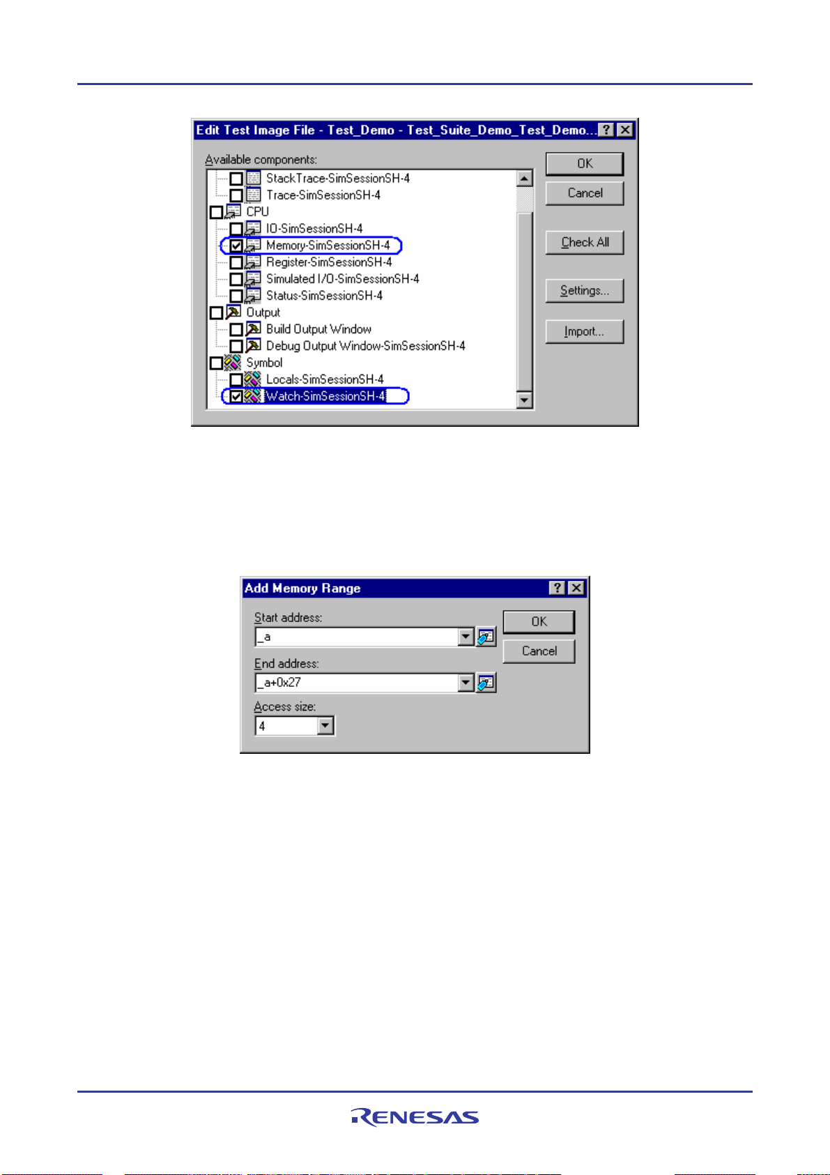
High-performance Embedded Workshop 1. Overview
4. The Memory content at the address of an array is saved into the test-image file. Double-click Memory-xxxxxx
under CPU in Available components. The Edit Test Memory Ranges dialog box opens.
5. Click the Add button to display the Add Memory Range dialog box.
6. Enter the start address of an array in Start address and end address in End address and select the size in
Access size.
7. Click the OK button.
8. Click the OK button in the Edit Test Memory Ranges dialog box.
9. The content of array element "a[6]" in the "Watch1" sheet is saved into the test-image file. Double-click
Watch-xxxxxx under Symbol in Available components of the Edit Comparison Settings dialog box. The
Edit Test Watch dialog box opens.
10. Select the checkbox of "a[6]" in Symbols.
11. Click the OK button.
REJ10J1837-0100 Rev.1.00 Nov. 16, 2008
31
Page 47
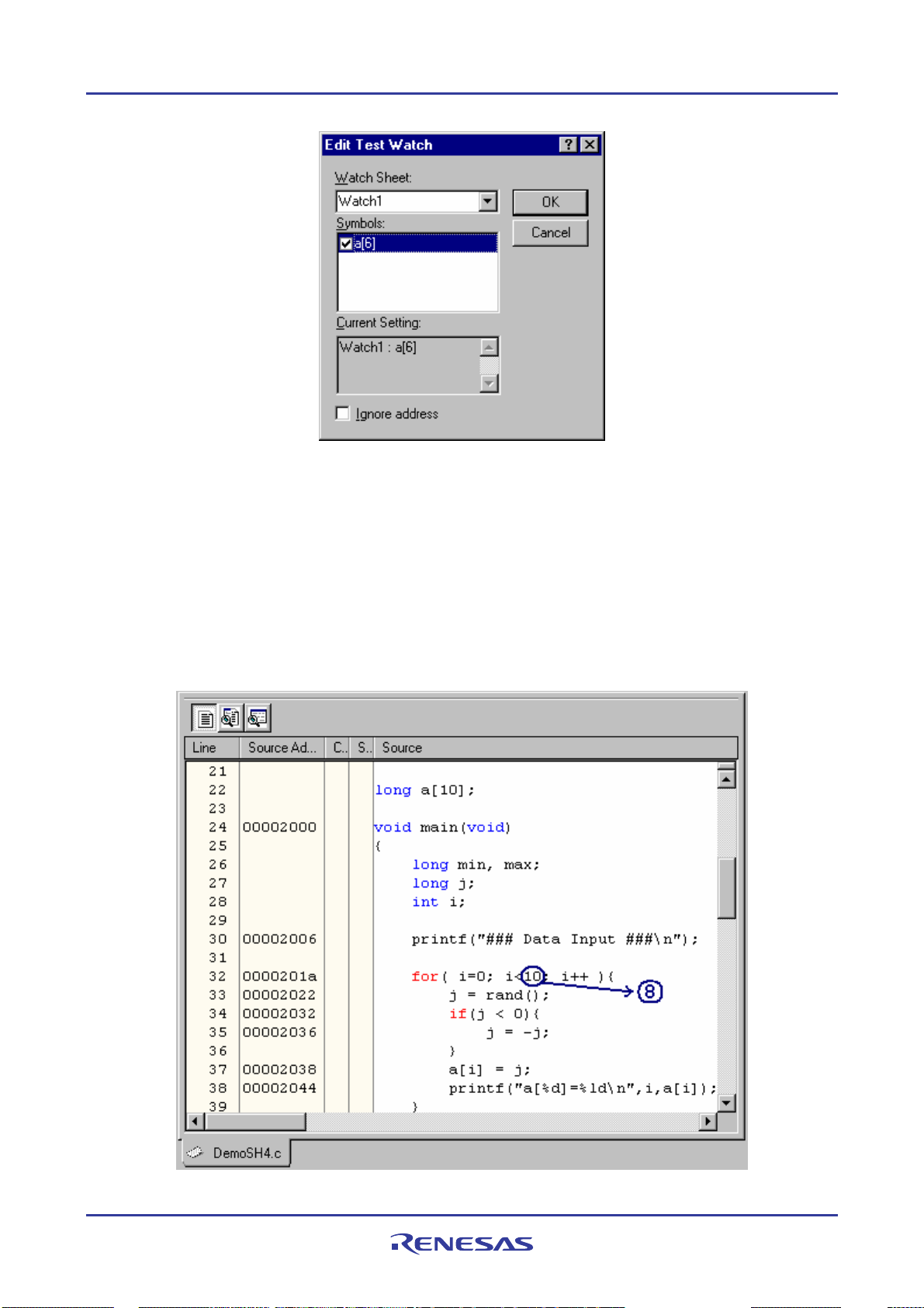
High-performance Embedded Workshop 1. Overview
12. Click the OK button in the Edit Test Image File dialog box.
In the state of current High-performance Embedded Workshop system, the test image specified in test item is acquired,
and the test image is saved to the test image file created at step 5.
1.14.8 Step 7: Modifying the program before the test
is example, the target of the test is a selected range of memory data in arrays. Then modify the program to reduce
In th
the number of times to store data into the array, so that the saved test-image information and the actual memory data
will not match.
REJ10J1837-0100 Rev.1.00 Nov. 16, 2008
32
Page 48

High-performance Embedded Workshop 1. Overview
1. Open a source file including a main function in the editor window and modify the program to reduce the
number of times to store data into the array.
2. Click the Save File button (
) on the Editor toolbar.
3. Right-click on the “Test_Demo” test icon to display a pop-up menu.
4. Select Run Test Case to start the test. The progress and result of the test are shown in the Test tab of the
Output window.
5. When the test is completed, the Test Browser window opens.
1.14.9 Step 8: Viewing the test result (unmatched)
You
can view the test result in the Test Browser window.
1. To view the details of unmatched data, doub le-click a test item with a red icon in the bottom tab.
2. When Symbol - Watch-xxxxxx is double-clicked, for example, the Test Comparison Details dialog box
appears as shown below. This dialog box shows the values of both the saved test-image information
(Src=xxxxxx) and the result of this test (Dest=xxxxxx) regard ing elements in arrays.
REJ10J1837-0100 Rev.1.00 Nov. 16, 2008
33
Page 49

High-performance Embedded Workshop 1. Overview
3. Clicking the Export button sav es the test resu lt into a text file.
4. Click the OK button.
1.14.10 Step 9: Modifying the program back and executing the test again
odify the program to restore the number of times to store data in the array and then execute the test.
M
1. Return th e number from 8 to 10 and build the program.
2. Click the Save File button (
) on the Editor toolbar.
3. Right-click on the “Test_Demo” test icon to display a pop-up menu.
4. Select Run Test Case to start the test.
5. When the test is completed, the Test Browser window opens.
1.14.11 Step 10: Viewing the test result (matched)
can view the test result in the Test Browser window. Make sure that the test result now matches the saved test-
You
image information.
REJ10J1837-0100 Rev.1.00 Nov. 16, 2008
34
Page 50
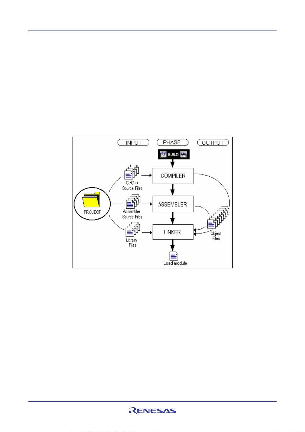
High-performance Embedded Workshop 2. Build Basics
2. Build Basics
This chapter explains the general basic functions of the High-performance Embedded Workshop whilst the more
advanced features can be found in chapter 3, Advanced Build Features.
2.1 The build process
The typical build process is outlined in the figure below. This may not be the exact build process that your installation
of High-performance Embedded Workshop will use, as it depends upon the tools that were provided with your
installation of High-performance Embedded Workshop (you may not have a compiler, for instance). In any case, the
principles are the same – each phase of the build takes a set of project files and builds them; if every file builds
successfully then the next phase is executed.
In the example shown in the figure above, the Compiler is the first phase, the Assembler is the second phase and the
Linker is the third and final phase. During the Compiler phase, the C/C++ source files from the project are compiled in
turn. During the Assembler phase, the assembler source files are assembled in turn. During the Linker phase, all library
files and output files from the Compiler and Assembler phases are linked together to produce the load module.
The build process can be customized in several ways. For instance, you can add your own phases, disable phases, delete
phases and so on. These advanced build issues are left to chapter 3, Advanced Build Features.
REJ10J1837-0100 Rev.1.00 Nov. 16, 2008
35
Page 51

High-performance Embedded Workshop 2. Build Basics
2.2 Configuring the Projects tab of the Workspace window
The Projects tab shows the current workspace, projects and files. You can quickly open any project file or dependent
file by double-clicking on its icon.
Right-clicking on a workspace opens a pop-up menu containing the available options.
Pop-up Menu Option Macro Recording Function
Insert Project - Adds a project to workspace.
Load All Projects - Loads all projects to workspace.
Collapse - Collapses the tree below a workspace icon.
Clean All Projects
Version Control - Executes a version control system.
Configure View - Configures the workspace view.
Properties - Displays workspace properties.
Deletes intermediate and output files from configurations in all projects in
this workspace.
Right-clicking on a project opens a pop-up menu containing the available options.
Pop-up Menu Option Macro Recording Function
Build
Set as Current Project
Remove Project - Removes a project from workspace.
Unload Project
OR
Load Project
Add Files - Adds files to a project.
Remove Files - Removes files from project.
Add Folder - Add folder to a project.
Build
Build All
Clean Current Project
Update All Dependencies - Updates all dependencies.
- Unloads a project
Builds out of date project files
Builds project files, regardless of whether the project files are out of date.
Deletes intermediate and output files from the current configuration in this
project.
Sets this project as the current project.
OR
Loads a project.
REJ10J1837-0100 Rev.1.00 Nov. 16, 2008
36
Page 52
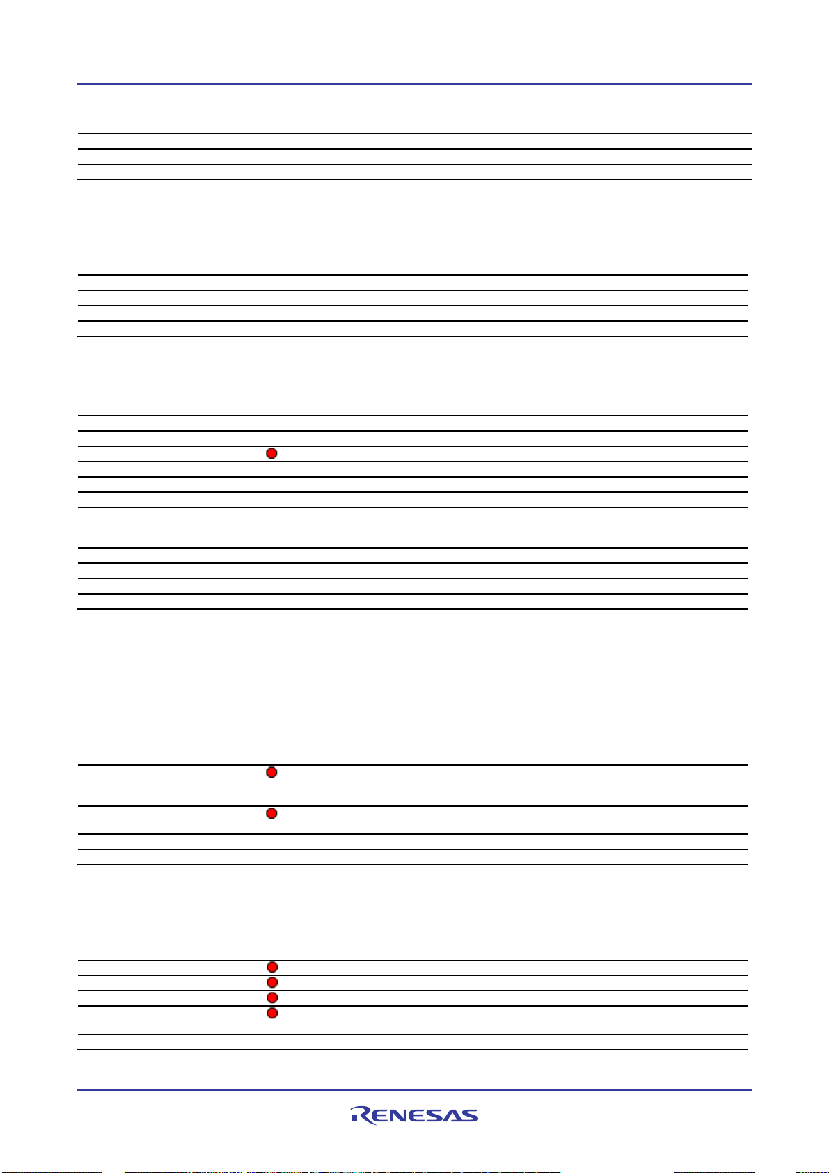
High-performance Embedded Workshop 2. Build Basics
Expand/Collapse - Expands or collapses the tree below a project icon.
Version Control - Executes a version control system.
Configure View - Configures the workspace view.
Properties - Displays project properties.
Right-clicking on a folder (other than Download module and Dependencies) opens a pop-up menu containing the
available options.
Pop-up Menu Option Macro Recording Function
Add Folder - Add a custom folder.
Rename Folder - Rename a folder.
Remove Folder - Remove a folder.
Configure View - Configures the workspace view.
Right-clicking on a project file opens a pop-up menu containing the available options.
Pop-up Menu Option Macro Recording Function
Open <file name> - Opens a file in the High-performance Embedded Workshop editor.
Open <file name> in external editor * - Opens a file in the external editor.
Build <file name>
Build Options - Sets build options.
Add File - Adds files to a project.
Remove File - Removes files from project.
Exclude Build
OR
Include Build
Version Control - Executes a version control system.
Configure View - Configures the workspace view.
Show Differences - Compares files.
Properties - Displays file properties.
- Excludes a project file from build
Builds a file.
OR
Includes a project file in build.
Note:
*. This option is available only when the Use external editor checkbox is selected in the Editor tab of the Options
dialog box opened via [Setup -> Options].
Right-clicking on the Download modules folder opens a pop-up menu containing the available options (Available
when the debugger is connected).
Pop-up Menu Option Macro Recording Function
Download all module
Download A New Module
Debug Settings - Opens the Debug Settings, which allows you to modify the debug settings.
Configure View - Configures the workspace view.
Downloads all modules in the Download modules list on the Target tab of
the Debug Settings dialog box (i.e. download modules shown under the
Download Modules folder in the Projects tab of the workspace window).
Opens the Download Module dialog box, which allows you to add
download modules.
Right-clicking on a download module opens a pop-up menu containing the available options (Available when the
debugger is connected).
Pop-up Menu Option Macro Recording Function
Download
Download (Debug Data Only)
Unload
Download A New Module
Remove - Removes the selected modules.
Downloads modules.
Downloads modules (debug data only).
Unloads modules.
Opens the Download Module dialog box, which allows you to add
download modules.
REJ10J1837-0100 Rev.1.00 Nov. 16, 2008
37
Page 53

High-performance Embedded Workshop 2. Build Basics
Debug Settings - Opens the Debug Settings dialog box, which allows you to modify the
Configure View - Configures the workspace view.
Relocate Module * - Opens a dialog box which allows you to select one directory for relocating
Properties - Shows the selected download module setting in the Download Module
debug settings.
all files retrieved from the download module.
dialog box. This download module setting can be modified. The download
module will be unloaded if it has already been downloaded.
Note:
*. If you use a debug-only project (i.e., "Debugger only - xxxxxx"), this menu option will be displayed.
Right-clicking on a file retrieved from the download module opens a pop-up menu containing the available options
(Available only when you use the debug-only project).
Pop-up Menu Option Macro Recording Function
Open <file name> - Opens a file in the High-performance Embedded Workshop editor.
Add File - Adds files to a project.
Configure View - Configures the workspace view.
Relocated file(s) - Opens a dialog box which allows you to select the same short filename
Properties - Displays file properties.
retrieved from the download module at a new location.
Right-clicking on the Dependencies folder opens a pop-up menu containing the available options.
Pop-up Menu Option Macro Recording Function
Configure View - Configures the workspace view.
Right-clicking on a dependence file opens a pop-up menu containing the available options.
Pop-up Menu Option Macro Recording Function
Version Control - Executes a version control system.
Configure View - Configures the workspace view.
Show Differences - Compares files.
Properties - Displays file properties.
For details on "Current project", "Loaded project" and "Unloaded project", see section 2.12, Setting the current project.
2.3 Project files
In order for the High-performance Embedded Workshop to be ab le to build your application, you must first tell it which
files should be in the project and how each file should be built (see the figure below).
REJ10J1837-0100 Rev.1.00 Nov. 16, 2008
38
Page 54

High-performance Embedded Workshop 2. Build Basics
2.3.1 Adding files to a project
Before
building an application, select files to configure the application.
To add files to a project
1. Files can be added to the active project only. Select one of the following operations to open the Add files to
project 'project name' dialog box:
• Select [Project -> Add Files], OR
• Right-click on the project within the Projects tab of the workspace window and select Add Files from the
pop-up menu, OR
• Press the "Insert" key when the Projects tab of the Workspace window is selected.
2. Select the file(s) you wish to add to the project.
3. A Relative Path checkbox is available at the bottom of this dialog box. Selecting this checkbox allows the
files to be relative project files. These project files are relative to the workspace file and can also be placed
outside the workspace structure. Even if you re-allocate the entire source tree, the High-performance
Embedded Workshop is able to check the relative position of the files to find them. By default, this checkbox
is selected.
4. A Hide Project Files checkbox is available at the bottom of this dialog box. Selecting this checkbox only
shows the files not added to the current project. By default, this checkbox is not selected.
5. Click the Add button.
There are other ways to add files to a project
• Right-clicking on an open file in the Editor window displays a pop-up menu. If the file is already in the
project then the Add File To Project menu option is disabled. Select the Add File To Project menu option to
add the file to the current project.
• In the High-performance Embedded Workshop it is also possible to ‘drag and drop’ files from Windows
Explorer onto the Projects tab of the workspace window. For details, see section 2.3.2, Drag and drop of files
and folders.
®
REJ10J1837-0100 Rev.1.00 Nov. 16, 2008
39
Page 55

High-performance Embedded Workshop 2. Build Basics
Note:
If you add a file that has an unrecognized file type to the project, then the file will be added to the project, but certain
functions will be disabled for this file. When you double-click on a file with an unrecognized file type in the Workspace
window, the open operation is passed to the Windows
default ‘Open’ operation is then carried out as if the file was double-clicked in Windows
®
operating system (instead of opening the file in the editor). The
®
Explorer. To view the
currently defined extensions, use the File Extensions dialog box. See section 2.5, File extensions and file groups, for
further information.
2.3.2 Drag and drop of files and folders
is possible to ‘drag and drop’ files or folders from Windows® Explorer onto the Projects tab of the workspace
It
window. These files or folders can only be dropped onto a project in the active project or a user folder in the active
project. Note, however, that you cannot drag and drop files or folders onto multiple folders.
When you drag and drop files
The behavior depends on the destination.
• A file dropped onto the active project is added into the group folder of the file type. If a suitable group folder
does not exist, the High-performance Embedded Workshop creates it. For example, if you drop the file “test.c”
onto the active project, this file will be added to the group folder “C source file”.
• A file dropped onto a user folder is directly added to this folder. Even if a file with the same name is already in
the folder, the new file can be added to the folder only when these two files have different paths.
• If a file of an unrecognized file type is added to the project, this file is directly added to the project.
To drag and drop folders
Drag and drop of a folder from the Windows ® Explorer opens the Add Files From Folder dialog box, which allows
you to select the files in the folder that you wish to add to the project. This dialog box shows the names of all files
included in the folder that was dropped. Filename and File Type show the full paths of files and file types,
respectively.
REJ10J1837-0100 Rev.1.00 Nov. 16, 2008
40
Page 56

High-performance Embedded Workshop 2. Build Basics
1. In the dialog box, th e files are initially sorted by the file type in alphabetical order. If you click a column
header (of file names or types), the files will be sorted by the file name or type.
2. You can select multiple files by clickin g. If you then click on one of the checkboxes for the selected files or
press the Space key, checkboxes for all of the selected files will be switched ON or OFF (depending on the
previous state).
3. If the Show files in subfolders checkbox is selected, the dialog box also shows the files within subfolders
under the folder that was dropped. Otherwise the dialog box only shows the files within the folder that was
dropped. By default, this checkbox is selected.
4. If the Show source files only checkbox is selected, the dialog box on ly shows the files having the extension
specified for the source files in this project (e.g. C source files). Otherwise the dialog box shows all files. If the
High-performance Embedded Workshop cannot recognize the file type, “Unknown type” will be shown in the
File Type column. By default, this checkbox is selected.
5. If the Create folder structure in project checkbox is selected, files are added to the tree where the folder was
dropped. For example, when a folder “data” containing some files is dropped onto the tree, the files are added
into a user folder “data”, which is newly created.
If the Create folder structure in project checkbox is not selected, when you drop a folder onto a user folder,
files in the folder are added into this user folder. When a folder is dropped onto the active project tree, files in
the folder are added into the group folder of the file type (e.g. a file “main.c” is added into the group folder “C
source file”). If a suitable group folder does not exist, the High-performance Embedded Workshop creates it.
Files of an unknown type dropped onto the project are directly added to the project.
By default, this checkbox is not selected.
6. Clicking the Uncheck All button deselects all checkboxes, while clicking the Check All button selects all
checkboxes.
7. Clicking the OK button adds all selected files, which have tick marks in their checkboxes, to the project. Next
time this dialog box is opened, it shows the most recently used setting.
2.3.3 Removing files from a project
There are
three ways of removing files from a project
• Files can be individually removed from a project,
• A selection of fi l es can be re moved,
• All files can be removed.
To remove a file(s) from a project
1. Select one of the following operations to open the Remove Project Files dialog will be displayed:
• Select [Project -> Remove Files], OR
• Right-click on the project within the Projects tab of the workspace window and select Remove Files from the
pop-up menu.
2. Select the file(s) that you want to remove from the Project files list.
3. Click the Remove button to remove the file(s), or click the Remove All button to remove all files from the list.
4. Click the OK button to remove the files from the project.
REJ10J1837-0100 Rev.1.00 Nov. 16, 2008
41
Page 57

High-performance Embedded Workshop 2. Build Basics
To remove selected files from a project using the Projects tab of the Workspace window
1. Select the files that you want to remove in the Projects tab of the Workspace window. Multiple files can be
selected by holding down the SHIFT or CTRL key.
2. Press Delete.
3. A confirmation dialog box opens for you to select whether or not to delete the selected files from the project.
To delete the selected files, select Yes. Otherwise select No.
If you do not wish to open this confirmation dialog box, select the Don’t ask this question again checkbox.
To open this dialog box again, select [Setup -> Options] to open the Options dialog box. Select the Delete
file from project checkbox on the Confirmation tab. By default, this checkbox is selected.
2.3.4 Excluding a project file from build
le in a project can be excluded from build on a configuration by configuration basis.
A fi
To exclude a project file from build
1. Click on the file that you want excluded from build, in the Projects tab of the Workspace window.
It is also possible to select several files by using a mouse or inputs through the keyboard as follows:
• To select several files
Click the files while pressing the CTRL key.
REJ10J1837-0100 Rev.1.00 Nov. 16, 2008
42
Page 58

High-performance Embedded Workshop 2. Build Basics
• Select several files as a range
Click a file as the start of the range. Then keep pressing the SHIFT key and click another file as the end of
the selected range.
2. Take either of the two ways listed below. A red cross (
) will appear on the file’s icon, and the file will be
excluded from build.
• Select Exclude Build <file>, where <file> is the name of the selected file, from the pop-up menu opened
by right-clicking. <file> is not displayed if several files are selected.
• Select [Build -> Include/Exclude Build].
2.3.5 Including a project file in build
le that has been excluded from build can be included again.
A fi
To include a project file in build
1. Click on a file that has previously been excluded from build, in the Projects tab of the Workspace window.
It is also possible to select several files by using a mouse or inputs through the keyboard as follows:
• To select several files
Click the files while pressing the CTRL key.
• Select several files as a range
Click a file as the start of the range. Then keep pressing the SHIFT key and click another file as the end of
the selected range.
2. Take either of the two ways listed below. The red cross will b e removed from the file’s icon (
), and the file
will be included in build.
• Select Include Build <file>, where <file> is the name of the selected file, from the pop-up menu opened
by clicking the right-mouse button. <file> is not displayed if several files are selected.
• Select [Build -> Include/Exclude Build].
2.4 User folders in the workspace
In the High-performance Embedded Workshop it is possible to add folders to the Projects tab of the workspace window.
This allows you to logically group your files into certain areas within a project. The folder can be set to any name and
this is entered in a dialog box. The operations listed below are not allowed, however, for folders Download modules
and Dependencies that are automatically displayed.
To add a user folder
1. Select the project on the Projects tab of the Workspace window.
2. Right-click and select Add Folder.
3. Enter the name in Folder of the Add Folder dialog box.
4. Click OK.
5. You can now drag and drop files into this folder to group them logically.
To add a sub-folder
1. Select the folder on the Projects tab of the Workspace window.
2. Right-click and select Add Folder.
3. Enter the name in Folder of the Add Folder dialog box
REJ10J1837-0100 Rev.1.00 Nov. 16, 2008
43
Page 59

High-performance Embedded Workshop 2. Build Basics
4. Click OK.
5. You can now drag and drop files into this folder to group them logically.
To drag and drop a folder
Drag a folder in the active project from the Projects tab of the Workspace window.
• If the folder is dropped onto the active project, the folder is directly added into the project.
• If the folder is dropped onto a user fo lder in the active project, the folder is added into the user folder.
You can also drag folders from the Windows® Explorer and drop it into the Projects tab of the workspace window. For
details, see section 2.3.2, Drag and drop of files and folders.
To remove a user folder
1. Select the folder on the Projects tab of the Workspace window.
2. Select one of the following operations (the folder must be empty):
• Press the Delete key.
• Right-click and select Remove Folder from the pop-up menu.
To modify a user folder name
1. Select the folder on the Projects tab of the Workspace window.
2. Right-click and select Rename Folder from the pop-up menu.
3. Enter the new name in Folder of the Rename Folder dialog box.
4. Click OK.
2.5 File extensions and file groups
The High-performance Embedded Workshop can identify files by their extension. The system defines certain
extensions depending upon the tools that are being used. For example, if you are using a compiler then the .c extension
will be in the ‘C source file’ group and will be used as input to the compiler phase. Additionally, the High-performance
Embedded Workshop allows you to define your own extensions. For example, if the project you are developing uses
assembler source files the default extension may be .src. If you would like to use a different extension instead of .src
(e.g. .asm) then you can define a new extension and request that the High-performance Embedded Workshop treats it in
the same way as a .src file.
File extensions and file groups can be viewed and modified via the File Extensions dialog box, which is invoked by
selecting [Project -> File Extensions]. This dialog box displays all the extensions and file groups that are defined
within the current workspace.
REJ10J1837-0100 Rev.1.00 Nov. 16, 2008
44
Page 60
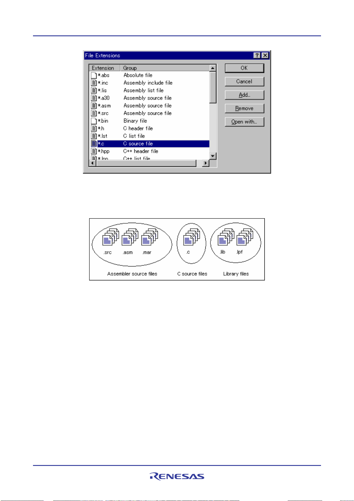
High-performance Embedded Workshop 2. Build Basics
The File Extensions list is divided into two columns. On the left are the file extensions, and on the right are the file
groups associated with the extensions. Many file extensions can belong to the same group. For example, assembler
source files may have several extensions in a single project (e.g.
.src, .asm, .mar etc.).
2.5.1 Associating an application with a file group
In add
ition to opening a file with the editor, the File Extensions dialog box allows you to associate any application with
any file group so that when you double-click on a file in the Projects tab of the Workspace window, the appropriate
application is launched with the file.
REJ10J1837-0100 Rev.1.00 Nov. 16, 2008
45
Page 61
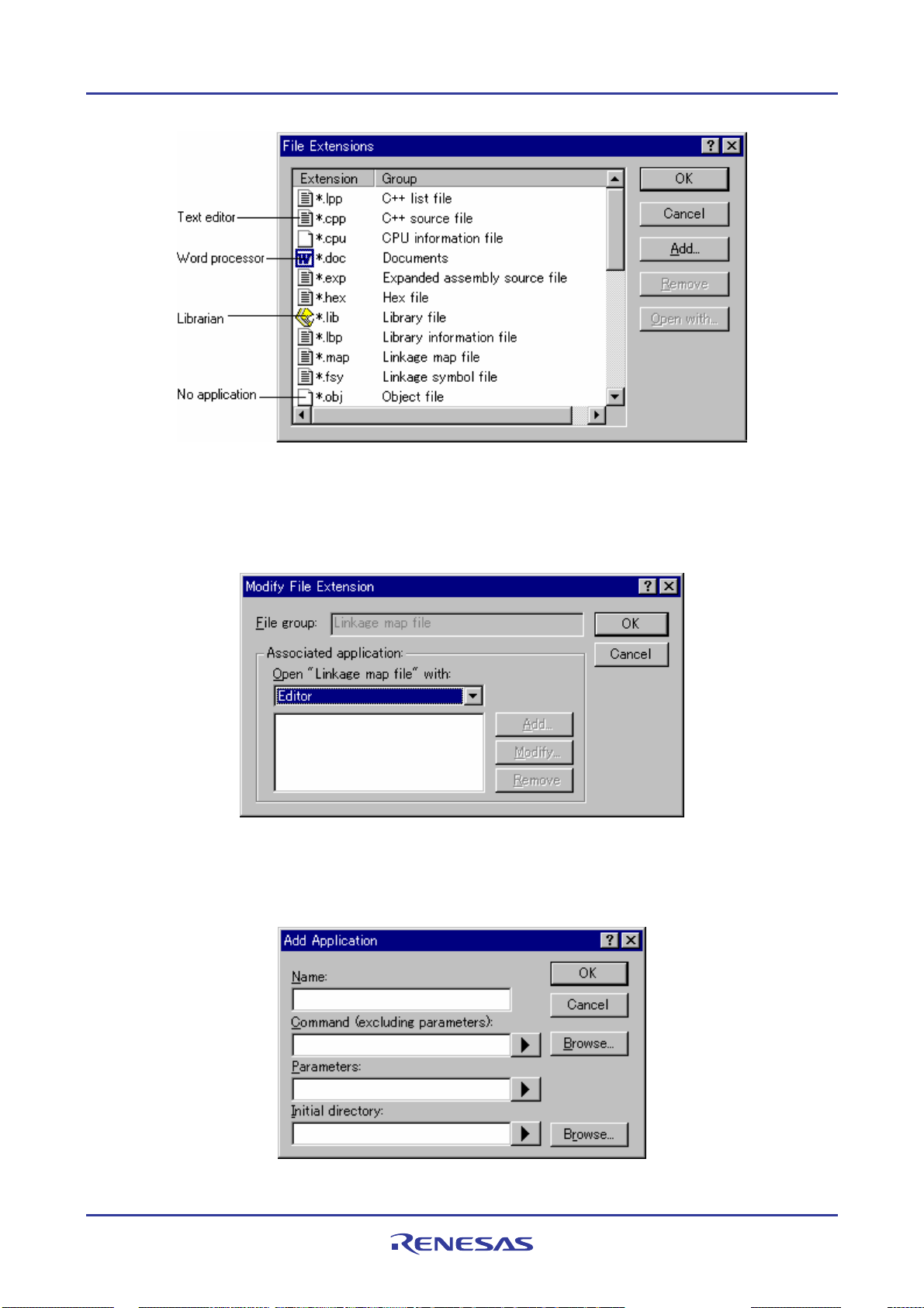
High-performance Embedded Workshop 2. Build Basics
To associate an application with a file group
1. Select [Project -> File Extensio ns]. The File Extensions dialog box opens.
2. Select the file group that you want to associate fro m the file extension s list.
3. Click the Open with button. The Modify File Extension dialog box opens.
4. Select None to remove any association, Editor to open this type of file in the internal/external editor, or select
Other to open this type of file with a specific application. If you select Other, you can either specify a new
application, or select any previously define d application from the drop-down list. Click the Add button to
define a new application. The Add Application dialog box opens.
REJ10J1837-0100 Rev.1.00 Nov. 16, 2008
46
Page 62

High-performance Embedded Workshop 2. Build Basics
Enter the name of the tool into the Name field. Enter the full path to the tool in the Command field (do not
include any parameters). Enter the parameters that are required to open a file into the Parameters field. Be
sure to use the
$(FULLFILE) placeholder to specify the location of the file (see Reference 5, Placeholders, for
more information on placeholders). Enter the initial directory in which you would like the application to run
into the Initial directory field. Click the OK button to finish creating the application. Click the Modify
button to modify an application. The Modify Application dialog box will be displayed. This dialog is the
same as the Add Application dialog box described above except that the Name field is read-only. Modify the
settings as desired and then click the OK button.
5. Click the OK button to set the application for the selected file group.
2.5.2 Creating a new file extension and file group
ou want to manage files that are not, by default, recognized by the High-performance Embedded Workshop (e.g.
If y
documents) then you need to create a new extension and a new file group.
To create a new file extension in a new file group
1. Select [Project -> File Extensio ns]. The File Extensions dialog box opens.
2. Click the Add button. The Add File Extension dialog box opens.
3. Enter the extensio n that you want to define into the File extension field. Use only alphanumeric and an
underscore as characters of a file extension string. The drop-down list contains all extensions that are
undefined in the current project. Selecting one of these extensions will add the text to the file extension field
automatically.
4. Select the Extension belongs to new group option and enter a description that defines this new file group.
5. At this stage it is possible to change the associated application. There are four available choices in the Open
"<extension group>" with drop-down list:
• Editor
• None
• Other
• Windows default
REJ10J1837-0100 Rev.1.00 Nov. 16, 2008
47
Page 63

High-performance Embedded Workshop 2. Build Basics
If Editor is selected, the Open File function in the workspace window causes the file to be opened in the Highperformance Embedded Workshop editor. If None is selected then the Open File operation is disabled when it is
attempted. Selecting Other allows you to configure another tool for the Open File operation. See section 2.5.1,
Associating an application with a file group, for more details. If Windows default is selected then the Open File
function in the Workspace window passes the Open File operation to the Windows
selects the default behavior for this file extension as defined in Windows
®
Explorer.
®
operating system. This then
6. Click the OK button to add the extension to the File Extensions list.
2.5.3 Creating a new file extension
our files use a different extension from those accepted by the High-performance Embedded Workshop for a given
If y
phase (e.g. your assembler source files are
.asm but the High-performance Embedded Workshop only recognizes .src),
then you need to create a new extension and add it to an existing file group. This process is described below.
To create a new file extension in an existing file group
1. Select [Project -> File Extensio ns]. The File Extensions dialog box opens.
2. Click the Add button. The Add File Extension dialog box opens.
3. Enter the extensio n that you want to define into the File extension field. Use only alphanumeric and an
underscore as characters of a file extension string. The drop-down list contains all extensions that are
undefined in the current project. Selecting one of these extensions will add the text to the file extension field
automatically.
4. Select the Extension belongs to an existing group option and select the group to which you would like to add
this new extension.
5. Click the OK button to add the extension to the File Extensions list.
REJ10J1837-0100 Rev.1.00 Nov. 16, 2008
48
Page 64

High-performance Embedded Workshop 2. Build Basics
2.6 Setting build options
Once you have added the necessary files to the project, the next step is to instruct the High-performance Embedded
Workshop on how to build each file. To do this, you will need to select a menu option from the Build menu. The
contents of this menu depend upon which tools you are using.
To set options for a build phase
1. Select the Build menu and select the phase whose options you would like to modify.
2. A dialog box will be displayed allowing you to specify the options.
3. After making your selections, click the OK button to set them.
To obtain further information, use the context-sensitive help button or select the area in which you need assistance and
press F1.
2.7 Build configurations
The High-performance Embedded Workshop allows you to store all of your build options into a build configuration, i.e.
you can ‘freeze’ all of the options and give them a name. Later on, if you select that configuration, all options for all of
the build phases will be restored. These configurations also allow the user to specify debugger settings for a build
configuration. This means that each configuration can be targeted at a different end platform.
The figure below shows three configurations: Default, MyDebug and MyOptimized. In the first configuration,
Default, each phase (compile and assemble) is set to its standard settings. In the second configuration, MyDebug, each
file is being built with debug information switched on. In the third configuration, MyOptimized, each file is being built
with optimization on full and without any debug information. The developer of this project can select any of those
configurations and build them without having to return to the options dialogs to set them again.
REJ10J1837-0100 Rev.1.00 Nov. 16, 2008
49
Page 65

High-performance Embedded Workshop 2. Build Basics
2.7.1 Selecting a build configuration
To select the current configuration
1. Select [Build -> Build Configura tions]. The Build Configurations dialog box opens.
2. Select the build configuration that you want to use from the Current Configuration drop-down list.
3. Click the OK button.
You can also select a different build configuration by selecting it from the Current Configuration drop-down list on the
Standard toolbar.
2.7.2 Adding a new build configuration
To add a new build
configuration
1. Select [Build -> Build Configura tions]. The Build Configurations dialog box opens.
2. Click the Add button. The Add Configuration dialog box opens.
3. Enter the new build configuration name into the Configuration name field. As you enter the new build
configuration name, the directory underneath changes to reflect the configuration directory that will be used.
4. Select one of the existing bu ild configurations, on which you want to base the new build configuration, from
the Based on configuration drop-down list.
5. Click the OK buttons on both dialogs to complete the creation of the new build configuration.
2.7.3 Removing a build configuration
remove a build configuration
To
1. Select [Build -> Build Configura tions]. The Build Configurations dialog box opens.
2. Select the build co nfiguration to remove and click the Remove button.
3. Click the OK button to close the Build Configurations dialog box.
REJ10J1837-0100 Rev.1.00 Nov. 16, 2008
50
Page 66

High-performance Embedded Workshop 2. Build Basics
2.8 Building a project
2.8.1 Building individual files
The High-performance Embedded Workshop lets you build project files individually.
To build an individual file
1. Select the file to build from the Projects tab of the Workspace window.
2. Select one of the following operations:
• Click the Build File toolbar button (
), OR
• Select Build <file> from the pop-up menu, OR
• Select the [Build -> Build File] menu option, OR
• Press CTRL+F7.
All output is redirected to the Build tab of the Output window.
2.8.2 Building a project
The Build
option only compiles or assembles those files that have changed since the last build. Additionally, it will
rebuild source files if they depend upon a file that has changed since the last build. For instance, if the file ‘TEST.C’
#include’s the file ‘HEADER.H’ and the latter has changed since the last build, the file ‘TEST.C’ will be recompiled.
To perform a build operation
Select one of the following operations:
• Click the Build toolba r but t on (
), OR
• Press F7, OR
• Select [Build -> Build], OR
• Right-click on a project in the Projects tab of the Workspace window and select [Build -> Build] from the
pop-up menu.
The Build All option compiles and assembles all source files, irrespective of whether they have been modified or not,
and links all of the new object files produced.
To perform a build all operation
Select one of the following operations:
• Click the Build All toolbar button (
), OR
• Select [Build -> Build All], OR
• Right-click on a project in the Projects tab of the Workspace window and select [Build -> Build All] from
the pop-up menu.
All output from a build or build all operation is redirected to the Build tab of the Output window. Both the Build and
the Build All operations will terminate if any project files produce errors.
REJ10J1837-0100 Rev.1.00 Nov. 16, 2008
51
Page 67
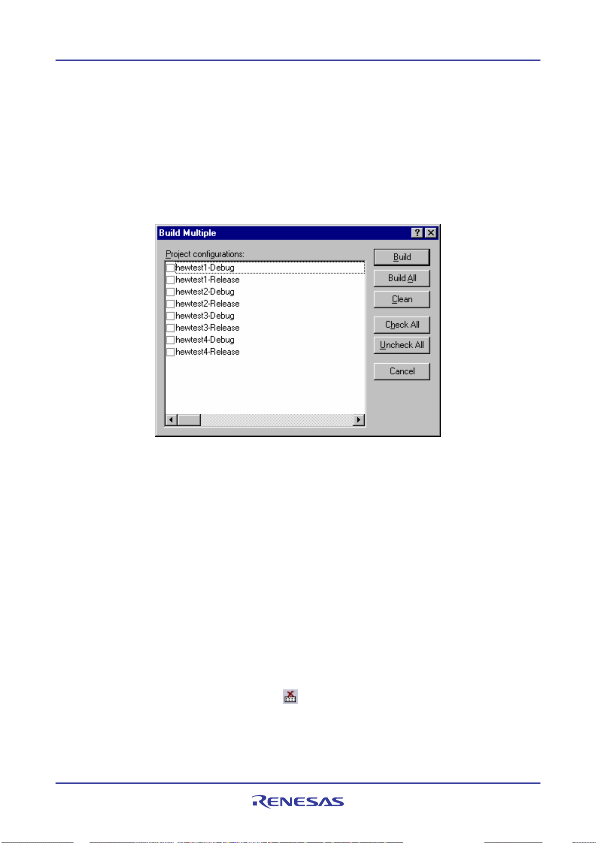
High-performance Embedded Workshop 2. Build Basics
2.8.3 Building multiple projects
The High-performance Embedded Workshop allows you to build multiple projects and configurations at once.
To build multiple projects
1. Select [Build -> Build Multiple]. The Build Multiple dialog box opens.
2. The Build Multiple dialog box gives you the choice of which projects and configurations to build. Select the
check boxes next to the projects and configurations that you want to build. For example, in figure below if you
wanted to build the entire “hewtest2” project you would check the “hewtest2-Debug” and the “hewtest2Release” selections and leave all other check boxes unchecked.
3. When you are happy with your chosen selection, click the Build button and the High-performance Embedded
Workshop will build the selected projects and configurations.
4. If you want to build all of the proj ects, click the Build All button. This will automatically select all projects
and configurations, and build them all.
5. If you also wish to delete intermediate and output files of the selected project or configuration, click the Clean
button. This does not execute the build.
6. Results from the build are displayed in the Build tab of the Output window in the same way as in a normal
build process.
7. If you use the dialog again it will restore the ch ecked status from the last time you used it.
2.8.4 Stopping tool execution
High-performance Embedded Workshop allows you to halt the build process once it is under way.
The
To stop tool execution
Select one of the following operations:
• Click the Stop Tool Execution toolbar button (
), OR
• Select [Build -> Stop Tool Execution].
The ‘Build Stopped by User’ message appears in the Build tab of the Output window.
REJ10J1837-0100 Rev.1.00 Nov. 16, 2008
52
Page 68

High-performance Embedded Workshop 2. Build Basics
Note:
Do NOT assume that any output from the tool you terminated is valid. It is recommended that you delete any output
files produced and ensure that the phase is executed again.
2.8.5 Deleting intermediate and output files produced in building
can delete intermediate and output files (produced in building) included in the current configuration in the project.
You
To delete intermediate and output files included in the current configuration in the project
Select one of the following operations:
• Select [Build -> Clean Current Project], OR
• Right-click on a project in the Projects tab of the workspace window. Select [Build -> Clean Current
Project] from the pop-up menu.
A confirmation dialog opens for you to select whether or not to delete all intermediate and output files produced in
building. To delete all files, select Yes. Otherwise select No or Cancel.
If you do not wish to open this confirmation dialog box, select the Don’t ask this question again checkbox.
To open the confirmation dialog box again
1. Select [Setup -> Options]. The Options dialog box opens.
2. Select the Confirmation tab.
3. Select the Clean project checkbox. This checkbox is selected by default.
4. Click OK.
To delete intermediate and output files in all projects of the workspace
Select one of the following operations:
• Click the Clean All Projects toolbar button (
), OR
• Select [Build -> Clean All Projects], OR
• Right-click on a workspace in the Projects tab of the workspace window. Select [Clean All Projects] from the
pop-up menu.
A confirmation dialog opens for you to select whether or not to delete all intermediate and output files produced in
building. To delete all files, select Yes. Otherwise select No.
REJ10J1837-0100 Rev.1.00 Nov. 16, 2008
53
Page 69

High-performance Embedded Workshop 2. Build Basics
If you do not wish to open this confirmation dialog box, select the Don’t ask this question again checkbox.
To open the confirmation dialog box again
1. Select [Setup -> Options]. The Options dialog box opens.
2. Select the Confirmation tab.
3. Select the Clean workspace checkbox. This checkbox is selected by default.
4. Click OK.
The Build tab in the Output window shows all projects and configurations in which intermediate and output files have
been deleted.
You can select multiple configurations and delete intermediate and output files produced in building. For details, see
section 2.8.3, Building multiple project s.
Note:
The High-performance Embedded Workshop dele te s rel oc a ta ble and absolute files. Linkage list files (".MAP") and
assembly-program list files (".LIS") are not deleted. Also note that the extension for absolute files differs depending on
the selected format.
2.8.6 Configuring the Build tab of the Output window
The Build tab
shows the output from any build process (e.g. compiler, assembler and so on). If an error is encountered
in a source file, an icon and the error message will be displayed in the Build tab, along with the source file name and
line number.
If you click on a toolbar button or pop-up menu option associated with display of error messages, the line of the error
message will be highlighted (with text in white and its background in dark blue) and the editor will show the source
code of that line (if the line has any source code).
Double-clicking the line of an error message will also show the source code in the editor.
When you attempt an operation to display an error or warning, the status bar shows this error or warning message.
You can also customize the Build tab so that the texts in the lines of error messages will be highlighted in a color
different from that of the texts in other lines. The figure below shows the error messages in red and warnings in green as
an example.
REJ10J1837-0100 Rev.1.00 Nov. 16, 2008
54
Page 70
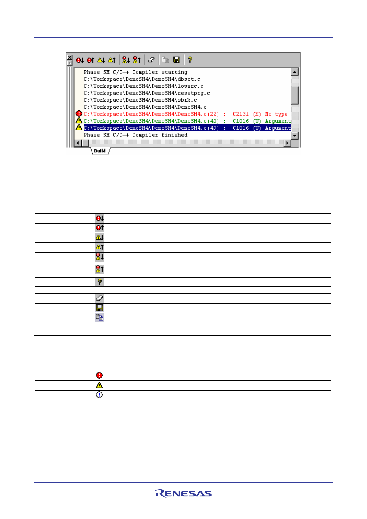
High-performance Embedded Workshop 2. Build Basics
Right-clicking displays a pop-up menu containing available options.
A basic operation is allocated to the toolbar.
The functions of Toolbar display and Customize toolbar are also included in the pop-up menu displayed by right-
clicking the toolbar area.
Pop-up Menu Option Toolbar Button Function
-
-
-
Display next
Error/Warning/Info
Display previous
Error/Warning/Info
Help
Go to Error/Warning/Info - Goes to the associated source line.
Clear Window
Save
Copy
Toolbar display - Shows or hides the toolbar.
Customize toolbar - Customizes toolbar buttons.
Highlights the next occurrence of error and shows the source code in the editor.
Highlights the previous occurrence of error and shows the source code in the editor.
Highlights the next occurrence of warning and shows the source code in the editor.
Highlights the previous occurrence of warning and shows the source code in the editor.
Displays the editor that generated the next build error or warning.
Displays the editor that generated the previous build error or warning.
Shows the help information about the line.
Clears the contents of the window.
Saves the contents of the window into a text file.
Copies the selected contents onto the Windows® clipboard.
The Build tab also shows an icon corresponding to the error message output by build execution.
Icon Name Icon Error Message Level
Build Error
Build Warning
Information
Error
Warning
Information
You can also customize the Build tab of the Output window so that the texts in the lines of error messages will be
highlighted in a color different from that of the texts in other lines.
To customize the current colors
1. Select [Setup -> Format Views] to open the Format Views dialog box.
2. Select the Output item from the tree in the left-hand section of the dialog box and expand it.
REJ10J1837-0100 Rev.1.00 Nov. 16, 2008
55
Page 71
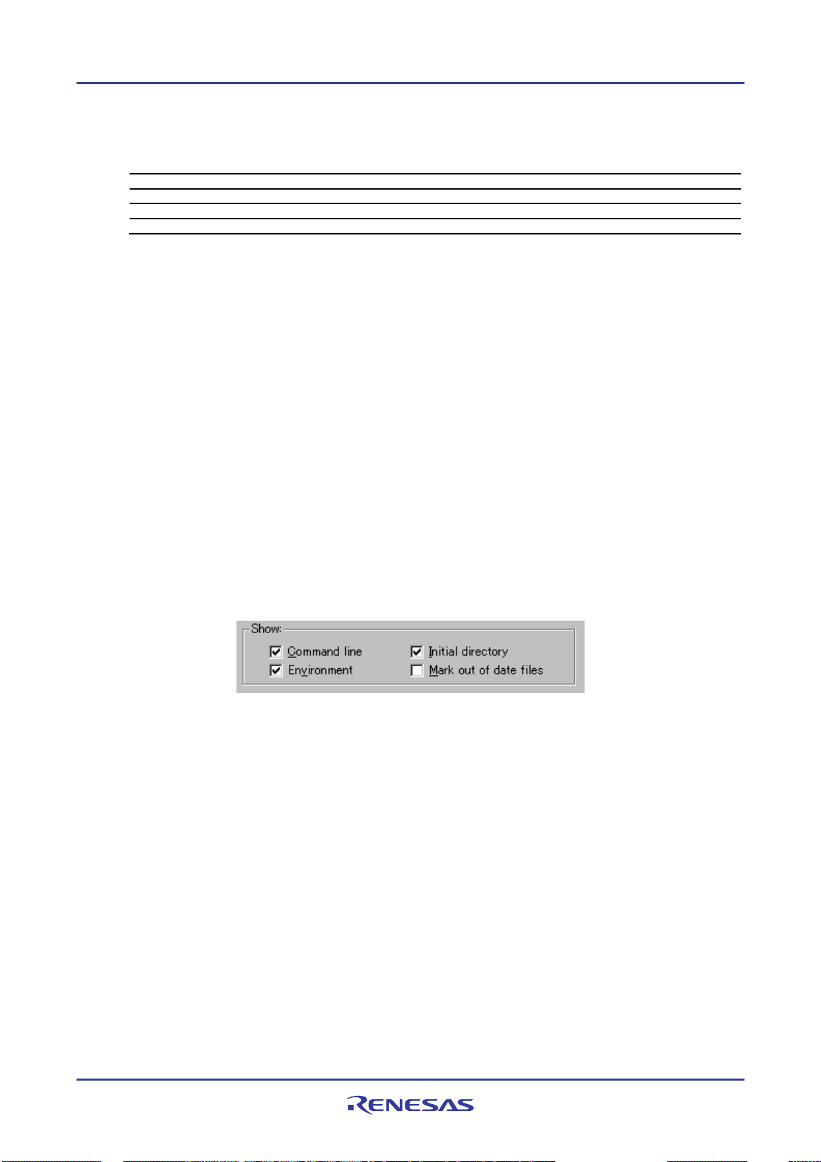
High-performance Embedded Workshop 2. Build Basics
3. Select the category for which you wish to change the color from the table below.
Category Foreground Color of the
Color Tab (Default)
Text SYSTEM SYSTEM All tabs All
Build Error Text Black White Build Error
Build Warning Text Black White Build Warning
Information Text Black White Build Information
Background Color of the
Color Tab (Default)
Tab(s) to be
Applied
Type of Output to be
Applied
4. Change the selection in the Foreground and Background lists of the Color tab.
5. Click the OK button.
2.8.7 Controlling the content of the Build tab of the Output window
It is often u
seful to display extra information (such as the command line options that are being app lied to a file) during a
build. The High-performance Embedded Workshop allows you to specify whether or not you wa nt such opt i o ns
displayed in the Build tab of the output window during a Build, Build All or Build File operation via the Options
dialog box.
To view or hide extra information during a build
1. Select [Setup -> Options]. The Options dialog box opens.
2. Select the Build tab.
3. Set the three check boxes in the Show group as follows:
• Command line controls whether the command line is shown as each tool is executed.
• Environment controls whether the environment is shown as each tool is executed.
• Initial directory controls whether the current directory is shown as each tool is executed.
2.8.8 Displaying out of date files in the Workspace window
Files up
dated later than the file generated by the previous build (i.e. out of date files) are marked in the workspace
window. In the window below the file "demo.c" is out of date.
When you click Build next time these files will be re-built. This is also displayed for dependent projects of the current
project.
The view of these files is updated whenever something that affects the build occurs, e.g. options changing, file
addition, dependencies changing, files modified, etc.
REJ10J1837-0100 Rev.1.00 Nov. 16, 2008
56
Page 72

High-performance Embedded Workshop 2. Build Basics
To display out of date files in the workspace window
1. Select [Setup -> Options]. The Options dialog box opens.
2. Select the Build tab.
3. Check the Mark out of date files check box.
4. Click OK.
2.9 File dependencies
A typical project will contain dependencies between files. For example, a C file may ‘#include’ one or more header files.
In complex projects, source files will include (or depend upon) others and this can quickly become difficult to manage.
However, the High-performance Embedded Workshop provides a dependency scanning mechanism whereby all files in
a project are checked for dependencies. Once complete, the Projects tab of the Workspace window will display an upto-date list with all the project file dependencies.
Initially, the dependencies for all files are contained within the Dependencies folder (although this can be modified by
configuring the projects tab).
REJ10J1837-0100 Rev.1.00 Nov. 16, 2008
57
Page 73

High-performance Embedded Workshop 2. Build Basics
File dependencies in a project are automatically updated at the following operation timings:
Operation Timing Specific Operation
Open workspace
Add a project to workspace Select [Project -> Insert Project]
Set the current project Select [Project -> Set Current Project]
Add files to a project Select [File -> Add Files]
Save files Select [File -> Save]
Build Select [Build -> Build]
Automatic dependency scanning Deselect the Disable automatic dependency scanning checkbox
Select option in the Welcome! dialog box
Select [File -> New Workspace]
Select [File -> Open Workspace]
To prevent automatic scanning of file dependencies in a project
1. Select [Setup -> Options]. The Options dialog box opens.
2. Select the Build tab.
3. Select the Disable automatic dependency scanning checkbox. This checkbox is not selected by default.
4. Click OK.
Note:
Selecting this option clears all file dependencies in a project. To manually update file dependencies in a
project, see "To manually update file dependencies in a project".
REJ10J1837-0100 Rev.1.00 Nov. 16, 2008
58
Page 74

High-performance Embedded Workshop 2. Build Basics
When [Build -> Build] is selected, a confirmation dialog box appears to ask if you wish to update the file dependencies
before executing the build.
If you have not manually updated dependency data, it may be out of date.
When you want dependency data to be updated prior to build, select Yes.
If you select No, it executes "Build" based on current dependency scanning data.
If you do not wish to open this confirmation dialog box, select the Don’t ask this question again checkbox.
To open the confirmation dialog box again
1. Select [Setup -> Options]. The Options dialog box opens.
2. Select the Confirmation tab.
3. Select the Scan Dependencies Prior To Build checkbox. This checkbox is selected by default.
4. Click OK.
To manually update file dependencies in a project
Select one of the following operations:
• Select [Build -> Update All Dependencies], OR
• Right-click on a project in the Projects tab of the Workspace window and select [Build -> Update All
Dependencies] from the pop-up menu.
REJ10J1837-0100 Rev.1.00 Nov. 16, 2008
59
Page 75

High-performance Embedded Workshop 2. Build Basics
2.10 Configuring the Workspace window
If you right-click anywhere inside the Projects tab of the Workspace window, a pop-up menu will be invoked. Select
the Configure View menu option to modify the way in which information is displayed. The following four sections
detail the effect of each option on the Configure View dialog box.
Show Dependencies Under Each File
If you check the Show dependencies under each file checkbox, the dependent files are shown under the including
source file as a flat structure, i.e. the files themselves become folders (as in figure (ii) below). If this option is not
selected then a separate folder contains all dependencies (as in figure (i) below).
Show Standard Library Includes
By default, any dependent files found in standard include paths will not be shown (as in figure (j) below). For example,
in C code, if you write a ‘#include’ statement, such as ‘#include <stdio.h>’, stdio.h will not be listed as a dependent file.
To view such system include files, select the Show standard library includes checkbox (as in figure (jj) below).
REJ10J1837-0100 Rev.1.00 Nov. 16, 2008
60
Page 76
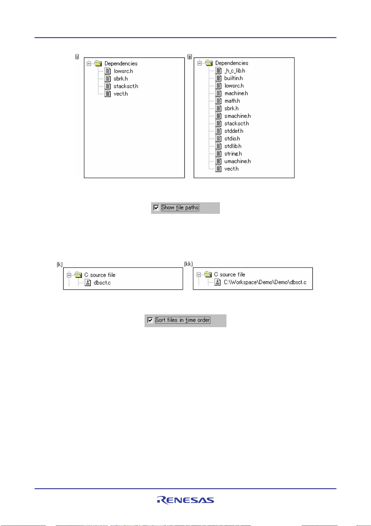
High-performance Embedded Workshop 2. Build Basics
Show File Paths
By default, any files will not be shown with their full path (as in figure (k) below). If the Show file paths checkbox is
selected, all of the files in the Projects tab of the Workspace window are shown with their full path, i.e. from a drive
letter (as in figure (kk) below).
Sorting the workspace window into time stamp order
When Sort files in time order option is selected, the workspace window is then sorted into file time stamp order. The
newest files are located at the top of list with the older files towards the bottom.
If files are updated after selecting this option, manually update the order of these files.
To manually update the file order
Select Refresh Order in the pop-up menu on the Projects tab of the Workspace window.
2.11 Inserting a project into the workspace
When a workspace is created, it contains only one project but, after it is created, you can insert new or existing projects
into the workspace.
REJ10J1837-0100 Rev.1.00 Nov. 16, 2008
61
Page 77

High-performance Embedded Workshop 2. Build Basics
To insert a new project into the workspace
1. Select [Project -> Insert Project]. The Insert Project dialog box opens.
2. Select the New project radio button.
3. Click the OK button. The Insert New Project dialog box opens.
4. Enter the name of the new workspace into the Project Name field. This can be up to 32 characters in length
and contain letters, numbers and the underscore character. Especially, do not use a minus sign, or a space. As
you enter the project name the High-performance Embedded Workshop will add a sub-directory for you
automatically. This can be deleted if desired.
5. Use the Browse bu tton to graphically select the directory in which you would like to create the project.
Alternatively, you can type the directory into the Directory field manually.
6. The project type list d isplays all of the available project types (e.g. Application, Library etc.). Select the type
of project that you want to create from this list.
7. Click the OK button to create the project and insert it into the workspace.
To insert an existing project into a workspace
1. Select [Project -> Insert Project]. The Insert Project dialog box opens.
2. Select the Existing project radio button.
3. Click the Browse b utton to search for the project database file (".HWP" file).
4. Click the OK button to insert the existing project into the workspace.
2.12 Setting the current project
A project can be in three states – the Current project, a Loaded project or an Unloaded project.
Since a workspace can contain many projects, only one of them can be the Current project at any time. This project is
the one that build actions and debug operations can be performed on (e.g. clicking the Build toolbar button will bu ild
the Current project).
To set a project as the current project
Select one of the following operations:
• Select the project that you want to make active from the [Project -> Set Current Project] sub-menu, OR
• Select the project from the Projects tab of the workspace window. Right-click to display the pop-up menu and
select the Set as Current Project option.
If the project is Loaded, it is possible to open the project’s directory and view the files. It is also possible to change the
builder or debugger options for the project. A Loaded project can also have tool executions performed on it from the
Tools menu.
REJ10J1837-0100 Rev.1.00 Nov. 16, 2008
62
Page 78

High-performance Embedded Workshop 2. Build Basics
To unload a project from the workspace
1. Select the Loaded project from the Projects tab of the workspace window.
2. Right-click to display the pop-up menu and select the Unload Project option. It is possible to select multiple
projects in the workspace window to perform this operation.
If the project is Unloaded, its icon appears ‘grayed’ in the Projects tab of the workspace window and no actions can be
performed upon it.
Unloaded projects can be loaded by the following operations.
To load all projects in the workspace
1. Select a workspace in the Projects tab of the workspace window.
2. Right-click to display the pop-up menu and select the Load All Projects option.
To load a project in the workspace
1. Select the Unloaded project from the Projects tab of the workspace window.
2. Right-click to display the pop-up menu and select the Load Project option. It is possible to select multiple
projects in the workspace window to perform this operation.
2.13 Specifying dependencies betw een projects
The projects within a workspace can be dependent upon one another so that when one project is built, all its dependent
projects are built first. This is useful if one project uses another in the workspace. For example, imagine that a
workspace contains two projects. The first project is a library, which is included by an application project. In this case
the library must have been built and up-to-date before the second application can build correctly. To achieve this
situation we can specify the library as a dependent (i.e. child) project of the application project. This would then allow
the library to be built first if it is out-of-date.
When a dependent project is built, the High-performance Embedded Workshop attempts to match the configuration in
the dependent project with that of the current project. This means that if the current configuration is ‘Debug’ then the
High-performance Embedded Workshop will attempt to build the ‘Debug’ configuration in the dependent project. If
this matched configuration does not exist then the High-performance Embedded Workshop will use the configuration
that was last used in the dependent project.
To make projects depend upon another
1. Select [Project -> Dependent Projects]. The Dependent Projects dialog box opens.
2. Select the project to which you would like to add dependents. When you do this, the Dependent projects list
will display all of the projects in the workspace (excluding the selected project).
3. The Dependent projects list has a checkbox for each project listed. Set the associated checkboxes to make
those projects depend upon the selected project.
4. Click on the OK button.
REJ10J1837-0100 Rev.1.00 Nov. 16, 2008
63
Page 79

High-performance Embedded Workshop 2. Build Basics
When there is a project dependent on the current project, the High-performance Embedded Workshop checks whether
building of the dependent project should be executed earlier than that of the current project.
When the current project is a parent, the dependency checking will be performed on its child project.
Even if another project is dependent on the child project, this dependent project will not be checked.
2.14 Removing a project from the workspace
To remove a project from a workspace
1. Select the project that you wish to remove in the Projects tab of the workspace window.
2. Right-click on the selected project to invoke a pop-up menu.
3. Select Remove Project.
Note:
You cannot remove the Current project from the workspace.
2.15 Relative projects paths in the workspace
In the High-performance Embedded Workshop when you add a project you can choose to add the project to the
workspace using a relative path. This allows you to position a file above the workspace directory and it will still be
relocated correctly if you relocate the High-performance Embedded Workshop workspace. The project is always
relative to the workspace so if the project is one directory above the workspace before it is moved the Highperformance Embedded Workshop will try to find the project in the same relative location after the relocation
procedure. This is especially useful if you are using a project shared between more than one workspace.
In older versions of High-performance Embedded Workshop this project would not have been relocated and would
have still tried to access the original file path. The older version of High-performance Embedded Workshop could only
relocate the projects, which were in a sub-directory of the workspace directory. This is still the standard behavior for the
High-performance Embedded Workshop.
To add the project to the workspace using a relative path
1. Select the project in the workspace window.
2. Right-click on the selected project to invoke a pop-up menu.
3. Select Properties.
4. Click the Project file specified as a relative path (in the .HWS file) checkbox to switch the relative file path
feature.
5. Click OK.
REJ10J1837-0100 Rev.1.00 Nov. 16, 2008
64
Page 80

High-performance Embedded Workshop 3. Advanced Build Features
3. Advanced Build Features
This chapter explains the advanced build concepts.
3.1 The build process revisited
“Chapter 2, Build Basics” began by describing the build process in terms of a compiler, an assembler and a linker. This
will be the case for most installations of the High-performance Embedded Workshop. However, if you want to begin
changing the build process (e.g. adding and removing phases) then it is important to understand more about the way in
which a build functions.
3.1.1 What is a build?
uilding a project means applying a set of tools upon certain input files in order to produce the desired output. Thus, we
B
apply a compiler upon C/C++ source files in order to create object files, we apply an assembler upon assembler source
files in order to create object files and so forth. At each step or ‘phase’ of the build, we apply a different tool upon a
different set of input files. The figure below presents a different view of the build process.
The High-performance Embedded Workshop provides the ability to change this build process via its Build Phases
dialog box, which can be accessed by selecting [Build -> Build Phases]. On the left-hand side are the phases that are
defined in the current project.
REJ10J1837-0100 Rev.1.00 Nov. 16, 2008
65
Page 81

High-performance Embedded Workshop 3. Advanced Build Features
The remainder of this chapter details the various functions that the Build Phases dialog box provides.
3.2 Creating a custom build phase
If you want to execute another tool before, during or after a standard build process then this can be achieved by creating
your own (i.e. custom) build phase.
To create a new custom build phase
1. Select [Build -> Build Phases] to invoke the Build Phases dialog box.
2. Click the Add button. This will invoke the New Build Phase wizard dialog box.
3. Follow the 4 steps below. To move forward and backward between steps click the Next > and < Previ o us
buttons respectively.
Step 1
The first step asks whether you want to create an entirely new phase or whether you want to add a system phase. A
system phase is a ‘ready-made’ phase which is already defined within the toolchain you are using (e.g. compiler,
assembler, linker, librarian, etc.) or a utility phase (e.g. file copy, complexity analyzer etc.). The Add an existing
system phase button is inactive if no more system phases are available. Select the Create a new custom phase button
to create your own build phase.
REJ10J1837-0100 Rev.1.00 Nov. 16, 2008
66
Page 82

High-performance Embedded Workshop 3. Advanced Build Features
Step 2
The second step asks what type of phase you would like to create. There are two choices: multiple or single. When a
multiple phase is executed, the command is applied to each file in the project of a certain file group. For example, if you
set the input file group to be C source files then the command will be executed once for each C source file in the
project. A single phase is executed once at most during a build.
The input file group list contains the current file groups defined for the project. It is possible to define multiple input
file groups by selecting the Multiple Groups entry in the input file group list.
REJ10J1837-0100 Rev.1.00 Nov. 16, 2008
67
Page 83

High-performance Embedded Workshop 3. Advanced Build Features
Once this choice has been made the input file group selection is displayed as Multiple Groups. This dialog box allows
the user to choose multiple input file groups for the custom phase being added to the project. To select a file group
check the box next to the file group’s name. One or more file groups can be selected in this dialog box.
Step 3
The third step requests the fundamental information about the new build phase. Enter the name of the phase into the
Phase name field. Enter the location of the program file into the Command field (do not insert any command line
options as these options are specified via the Options menu of the High-performance Embedded Workshop menu bar).
Specify the default options for the phase (i.e. what options you would like new files to take when added to the project)
into the Default Options field. If you have a preferred directory in which you would like this program to run (i.e. where
you want the current working directory to be set to before the tool is executed) then enter it into the Initial directory
field.
REJ10J1837-0100 Rev.1.00 Nov. 16, 2008
68
Page 84

High-performance Embedded Workshop 3. Advanced Build Features
Step 4
The fourth and final step allows you to specify any environment variables that the phase requires.
To add a new environment variable click the Add button (the Environment Variable dialog is displayed). Enter the
variable name into the Variable field and the variable’s value into the Value field and then click the OK button to add
the new variable to the list. To modify an environment variable select the variable from the list and then click the
Modify button. Make the required changes to the Variable and Value fields and then click the OK button to add the
modified variable to the list. To remove environment variables select the variable that you want to remove from the list
and then click the Remove button.
If the tool you are adding can display its output whilst the tool is running then use the Read Output on Fly option. This
will display the tool output as each line of output happens. If this option is set to off then the High-performance
Embedded Workshop will store all output that is being displayed by the tool, and display it in the Output window when
the tool has finished its operation. This can be a problem when the tool is running an operation that might take many
minutes, as it is difficult to see the progress of the current execution.
Note:
Using Read Output on Fly can cause problems when using certain tools on certain operating systems. If you are
having problems with tools locking up or freezing in High-performance Embedded Workshop then un-check the Read
Output on Fly option.
Click the Finish button to create the new phase. By default the new phase is added to the bottom of the Build phase
order list in the Build Order tab of the Build Phases dialog box.
REJ10J1837-0100 Rev.1.00 Nov. 16, 2008
69
Page 85

High-performance Embedded Workshop 3. Advanced Build Features
3.3 Ordering build phases
In a standard build (shown in figure below), you could add a phase at four different positions: before the compiler (1),
before the assembler (2), before the linker (3) or after the linker (4).
You may place your own custom phases or move system phases to any position in the build order. It is important to
remember that if the output of your custom phase can be input into another phase then the phase order must be correct if
the build is to behave as intended.
Select [Build -> Build Phases]. The Build Phases dialog box will be displayed. The build phase dialog box provides
facilities for ordering build phases via the Build Phases dialog box. It has two tabs, which are concerned with the
ordering of phases: Build Order and Build File Order. And then you can click OK button.
3.3.1 Build Order tab
The Build Order tab
) buttons is selected. The check box to the left of each phase indicates whether or not the phase is currently enabled.
(
displays the current order in which phases will be executed when the Build (
) or Build All
A phase can be toggled on/off by checking/unchecking its co rresponding checkbox respectively.
REJ10J1837-0100 Rev.1.00 Nov. 16, 2008
70
Page 86

High-performance Embedded Workshop 3. Advanced Build Features
To change the order of phases (system/custom) in a build or build all operation
1. Select the phase to be moved and then click the Move Up and Move Down buttons to move the phase up and
down respectively.
2. Click the OK button to set the new ordering.
To view the properties of a system phase
1. Select the system phase that you would like to view.
2. Click the Modify button.
3. The Command tab shows general information about the phase. This may include copyright information,
version information and so on.
4. Select the Environment tab to view the environment settings of the phase.
5. Click the OK button to close the dialog box.
To modify a custom phase
1. Select the custom phase that you would like to modify.
2. Click the Modify button. The Modify Phase dialog box will be invok ed with the Command tab selected.
3. Change the contents of Command and Initial directory as appropriate.
4. If there are multiple shot phases, select the file type to execute a phase from the Input file group (for multi-
shot phases only) drop-down list.
5. Select the Don’t check for input file(s) existence before executing checkbox if you don’t want the High-
performance Embedded Workshop to abort the execution of the phase if any of the input files do not exist.
6. Select the Read output on-the-fly checkbox if you want to display build output as it happens, rather than
showing the output at the end of each phase execution.
7. Select the Environment tab to ed it the environment settings for the phase.
REJ10J1837-0100 Rev.1.00 Nov. 16, 2008
71
Page 87

High-performance Embedded Workshop 3. Advanced Build Features
8. Use the Add, Modify and Remove buttons to add, modify and remove environment variables respectively.
9. Select the Output Syntax tab and define the error, warning, and information for the custom phase.
Messages that include filenames can only be handled as syntax. Thus all syntax defined on the Output Syntax
page should include filenames. Always use a placeholder to specify a filename.
When the lines showing error messages in the Build tab of the output window match the definition of Output
Syntax, you can find icons on the left to the error messages and view the source code in the editor.
If the Renesas SuperH C/C++ compiler is used, for example, the following error message may be output to
the Build tab of the output window.
C:\Workspace\SH\SH\resetprg.c(70) : C2225 (E) Undeclared name "a"
To define this error, type the following syntax.
$(FULLFILE)($(LINE))*(E)*
The correspondence between an error message and its syntax is as shown below.
Error Message (Example) Output Syntax (Example) Description
C:\Workspace\SH\SH\resetprg.c $(FULLFILE) Placeholder of the file name with its full path
(70) ($(LINE)) Placeholder of the line number enclosed with parentheses
: C2225 * Wild-card for “:” and error message number
(E) (E) (E) indicating an error
Undeclared name "a" * Wild-card for error message
There are some restrictions on these regular expressions. For example, it is not possible to define two unclear
strings next to each other, such as "**", "*$(FILEDIR)", or "$(FULLFILE)*".
It is also not possible to define ":", "\", and ".", which are commonly used in filenames and directory names,
to separate placeholders for filenames and directory names from other characters, such as
"$(FULLFILE):$(LINE)" or "$(FILENAME).*".
• When "Error" has been selected as the syntax type and the output message matches the definition of the
syntax:
An error icon (
) appears on the left to the message output as the result of building. Double-
clicking on the line displays the corresponding source code in the ed itor.
• When "Warning" has been selected as the syntax type and the output message matches the definition of
the syntax:
A warning icon (
) appears on the left to the message output as the result of building. Double-
clicking on the line displays the corresponding source code in the ed itor.
• When "Other" has been selected as the syntax type and the output message matches the definition of the
syntax:
An information icon (
Double-clicking on the line displays the corresponding source code in the editor.
REJ10J1837-0100 Rev.1.00 Nov. 16, 2008
72
) appears on the left to the message output as the result of building.
Page 88

High-performance Embedded Workshop 3. Advanced Build Features
The total number of errors and warnings will also be displayed in the Build tab of the output window at the
end of a build phase.
10. Use the Add, Modify and Remove buttons to add, modify and remove output syntax line formats respectively.
11. Click the OK button when all modifications have been made.
Note:
You can only change the environment of a system phase via the Tools Administration dialog box.
To remove a custom phase
1. Select the phase to be removed and click the Remove button.
2. Click the OK button to confirm the new settings.
To import a custom phase
1. Click the Import button. The Import Custom Phase dialog box is displayed, which allows you to browse to
an existing project, from which you want to import a custom phase.
2. Choose the location of the project, from which you want to import a custom phase. Once selected, the Import
Phase dialog box is displayed, which lists the custom phases in the imported project.
3. Once you have decided which phase to import, highlight it in the list and click the OK button. The phase will
then be added to the Build Phases dialog box, at the bottom of the build order.
3.3.2 Build File Order tab
ou were to select a C source file from the Workspace window and then activate [Build -> Build File] (or click the
If y
Build File toolbar button (
) you would expect the file to be compiled. Likewise, if you were to select an assembly
source file from the workspace window and then activate [Build -> Build File] you would expect the file to be
assembled. The connection between file group and which phase(s) to execute is managed by the Build File Order tab
of the Build Phases dialog box. The list displays all of the current phases that will be executed when the build file
operation is selected upon the file group shown in the File group list box. In figure below the “C source file” file group
is selected and the “Compiler” and “MyPhase” phases are associated with it. Entries in the Phase order list, of the
Build File Order tab, are added automatically as new entries are added to the Build Order tab.
For example, if you were to add a phase which takes C source files as input then this phase will be automatically added
to the list of phases to execute when a build file operation is applied to a C source file. If you don’t want a certain phase
to execute when [Build -> Build File] is selected then clear the check box to the left of the phase name in the Phase
order list.
REJ10J1837-0100 Rev.1.00 Nov. 16, 2008
73
Page 89
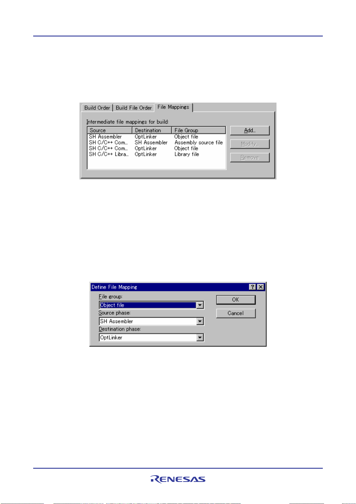
High-performance Embedded Workshop 3. Advanced Build Features
3.3.3 File Mappings tab
By default, the files input to a build phase are only taken from the project, i.e. all project files of the type specified in
the Select input file group drop-down list on the New Build Phase dialog box. Select [Build -> Build Phases]. The
Build Phases dialog box will be displayed. If you would like a build phase to take files output from a previous build
phase (these files are called intermediate files), then you must define this in the File Mappings tab of the Build Phases
dialog box.
A File Mapping means that you would like the output files of a certain type produced by one build phase (referred to as
the Source phase) to another build phase (referred to as the Destination phase). Such intermediate files are then passed
in addition to the project files.
To add a file mapping
1. Click the Add button. The Define File Mapping dialog box opens.
2. Select an existing file group to use for the new mapping from the File group drop-down list.
3. Select the source phase (i.e. the phase that generates the files) from the Source phase drop-down list.
4. Select the destination phase (i.e. the phase that takes these files) from the Destination phase drop-down list.
5. Click the OK button to create the new mapping.
To modify a file mapping
1. Select the mapping to be modified.
2. Click the Modify button. The Define File Mapping dialog box opens.
3. Modify the options as necessary.
4. Click the OK button to commit the changes.
To remove a file mapping
1. Select the mapping to be removed.
2. Click the Remove button.
3. Click the OK button to commit the changes.
REJ10J1837-0100 Rev.1.00 Nov. 16, 2008
74
Page 90

High-performance Embedded Workshop 3. Advanced Build Features
3.4 Setting custom build phase options
Once you have defined a custom phase, you will want to specify the command line options that should be used when it
is executed. Each defined phase has a menu option in the Build menu. To specify options for that phase select it. The
dialog that will be displayed depends on whether the custom phase selected was multiple or single (according to the
selection of phase type when it was created in the New Build Phase wizard).
If the phase selected was multiple then a list of project files is displayed on the left-hand side of the dialog to enable you
to specify the build options on a file by file basis. If the phase selected was single then there is no project file list
displayed. In either case, the three tabs below are available. This is where you can set the options that you want to apply
to the selected file(s). You can also choose which configurations are being viewed. In the configuration list, each
configuration is listed along with a special entry named Multiple configurations. If you select Multiple
configurations then the Select project configurations to modify dialog box is displayed which allows you to select
more than one configuration. This method is used throughout High-performance Embedded Workshop for modifying
multiple configurations at once.
3.4.1 Options tab
is tab allows you to define the command line options that will be passed to the phase. The Command field displays
Th
the command that was entered when you defined the phase. Enter into the Options field the command line arguments
that you would like to pass to the command. If you want to insert a placeholder, select the relevant placeholder from the
Placeholder drop-down list and then click the Insert button. See Reference 5, Placeholders, for more information on
placeholders.
REJ10J1837-0100 Rev.1.00 Nov. 16, 2008
75
Page 91

High-performance Embedded Workshop 3. Advanced Build Features
Note:
An error will be returned when the total number of characters of the command line options exceeds 256.
3.4.2 Output Files tab
This tab is
where you can specify the output files that will be produced by the phase. Before each file is passed into this
phase, the High-performance Embedded Workshop checks that the output files are of a less recent date than the input
file. If so, the phase will be executed for that file (i.e. input files have been modified since the output file or files were
last produced). If the files are up-to-date then the phase will not be executed.
Note:
If no output files are specified, the phase will execute regardless.
To add an output file
1. Click the Add button. The Add Output File dialog box will be invoked.
2. Enter the file path or browse to it using the Browse button.
3. Click the OK button to add this output file to the list.
To modify an output file
1. Select the output file that you would like to modify.
2. Click the Modify button. The Modify Output File dialog box opens.
3. Modify the fields as required.
4. Click the OK button to add the modified entry back to the list.
To remove an output file
1. Select the output file that you would like to remove.
2. Click the Remove button.
An output file’s path can include placeholders.
3.4.3 Dependent Files tab
This tab is
where you can specify the dependent files that are needed by the phase. Before each file is passed into this
phase, the High-performance Embedded Workshop checks that the dependent files are of a more recent date than the
input file. If so, the phase will be executed for that file (i.e. dependent files have been modified since the input files was
last modified). If not, the phase will not be executed.
REJ10J1837-0100 Rev.1.00 Nov. 16, 2008
76
Page 92
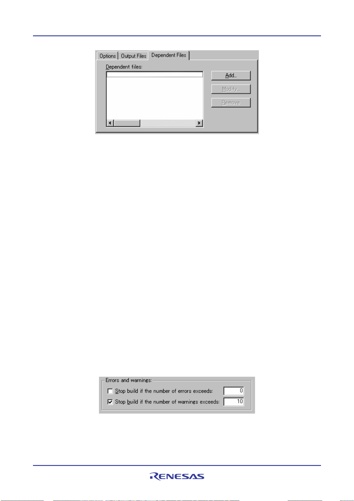
High-performance Embedded Workshop 3. Advanced Build Features
To add a dependent file
1. Click the Add button. The Add Dependent File dialog box opens.
2. Enter the file path or browse to it using the Browse button.
3. Click the OK button to add this output file to the list.
To modify a dependent file
1. Select the dependent file that you would like to modify.
2. Click the Modify button. The Modify Dependent File dialog box opens.
3. Modify the fields as required.
4. Click the OK button to add the modified entry back to the list.
To remove a dependent file
1. Select the dependent file that you would like to remove.
2. Click the Remove button.
A dependent file’s path can include placeholders.
3.5 Controlling the build
By default, the High-performance Embedded Workshop will execute all of the phases in a build and only stop if a fatal
error is encountered. You can change this behavior by setting the controls on the Build tab of the Options dialog box.
Select [Setup -> Options] to display the Options dialog box and then select the Build tab. If you want to stop the build
when a certain number of errors are exceeded then set the Stop build if the number of errors exceeds checkbox and
specify the error count limit in the field to the right. If you want to stop the build when a certain number of warnings are
exceeded then set the Stop build if the number of warnings exceeds checkbox and specify the warning count limit in
the field to the right.
In addition to specifying error and warning count limits, the Build tab also allows you to request that the Command
line, Environment and Initial directory of each execution should be displayed. Check the appropriate check boxes as
necessary.
REJ10J1837-0100 Rev.1.00 Nov. 16, 2008
77
Page 93
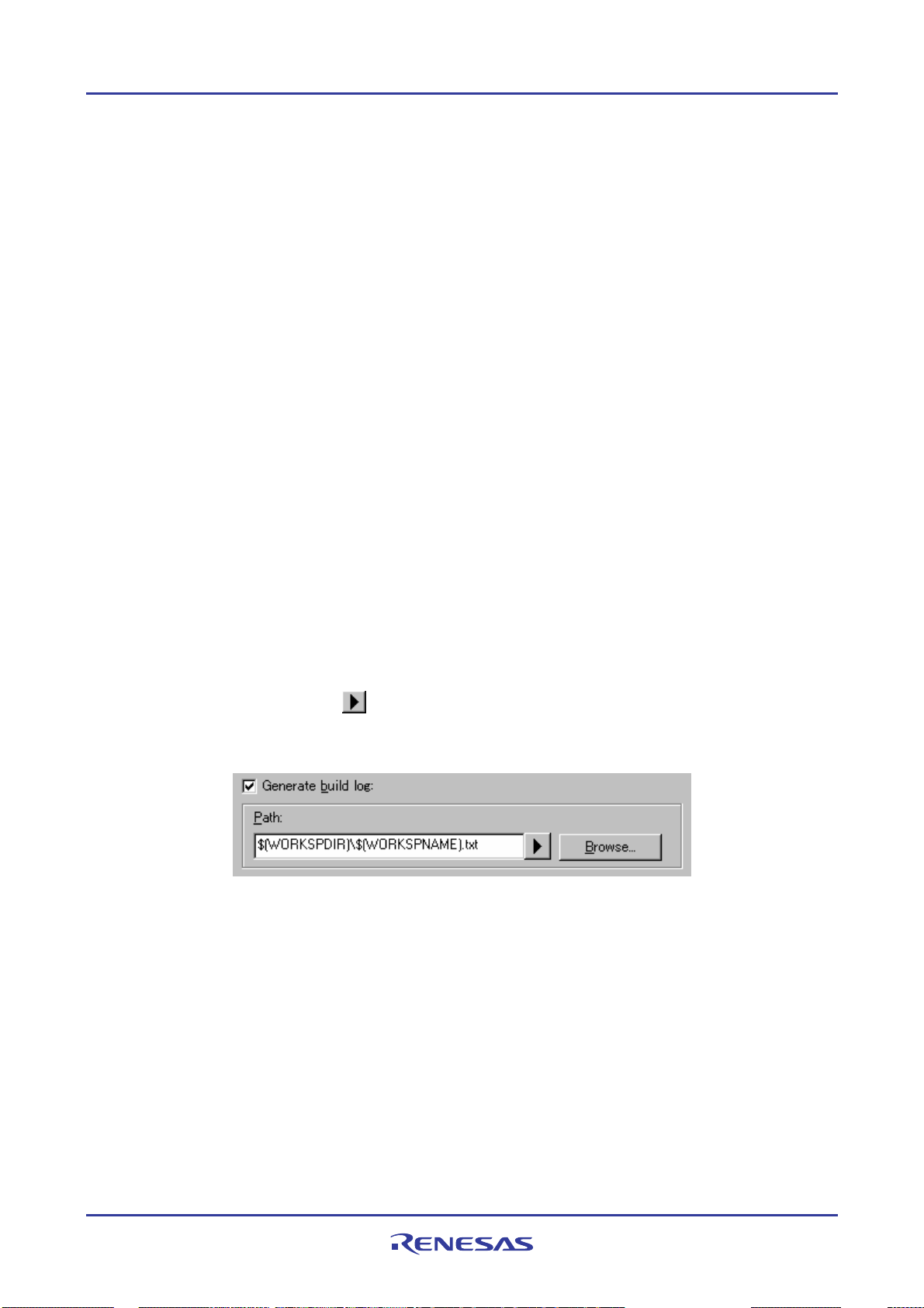
High-performance Embedded Workshop 3. Advanced Build Features
Notes:
• Irrespective of what these controls are set to, the build will always halt if a fatal error is encountered.
• When projects are dependent on one another, building stops if an error occurs in the child project and its parent
project will not be built.
• Note the following descriptions when you check the Stop build if the number of errors exceeds check box and
specify a number to the controls.
i. The build will stop immediately once the maximum number of errors or warnings is exceeded. It will not
continue to the end of the current phase.
ii. When the number of errors in one execution of a tool exceeds the specified number, the number of error
messages displayed on the “Output” window is the specified number plus one. A message saying that the
number of error has exceeded the specified number is NOT displayed on the Output window.
The same things as Stop build if the number of errors exceeds shown above hold also in Stop build if the number of
warnings exceeds. There is no correlation between Stop build if the number of errors exceeds and Stop build if the
number of warnings exceeds. They are independent.
3.6 Logging build output
The High-performance Embedded Workshop allows you to write the results of each build to file.
To specify a log file
1. Select [Setup -> Customize]. The Customize dialog box opens.
2. Select the Log tab.
3. Select the Generate build log checkbox.
4. Enter the full path of the log file into the Path field, or browse to it graphically by click ing the Browse button,
or click the placeholder button (
5. Click the OK button to confirm the new log file settings.
) and select the placeholder from the pop-up menu.
3.7 Changing toolchain version
If two or more versions of the same toolchain are registered in the High-performance Embedded Workshop, you can
choose a version of the toolchain on the Change Toolchain Version dialog box. To invoke the dialog, select [Tools ->
Change Toolchain Version]. Choose one of the versions from the Toolchain versi o n drop-down list and click the OK
button to enforce your choice.
REJ10J1837-0100 Rev.1.00 Nov. 16, 2008
78
Page 94

High-performance Embedded Workshop 3. Advanced Build Features
To show information about toolchain components, select a tool from the Toolchain build phase drop-down list on the
Change Toolchain Version dialog box, and click the Information button. A tool information dialog box will show
you information about the tool. Click the Close button to close the dialog box.
3.8 Generating a makefile
The High-performance Embedded Workshop allows you to generate a makefile associated with your workspace. Highperformance Embedded Workshop is capable of generating hmake, nmake, and gnumake compatible files. The make
tool to execute makefiles is operated in the DOS command prompt and thus the use of makefiles allows you to build
projects without High-performance Embedded Workshop.
The generated makefiles can be executed in the High-performance Embedded Workshop. For details, see section 3.9,
Using a makefile inside the High-performance Embedded Workshop system.
To generate a makefile
1. Open a workspace where you wish to generate a makefile (if the workspace includes two or more projects, the
active project must be one in which you wish to generate a makefile).
2. Select a configuration for generating a makefile.
3. Select [Build -> Generate Makefile]. The Generate Makefile dialog box opens.
REJ10J1837-0100 Rev.1.00 Nov. 16, 2008
79
Page 95

High-performance Embedded Workshop 3. Advanced Build Features
4. Select a makefile type in Generate makefile for.
• the current configuration in the currently active project
• all configurations in the currently active project
• all configurations in all loaded projects in the current workspace
5. Enter the file name in the MakeFile name edit box. To insert a placeholder, place the cursor at the position
where you wish to insert the placeholder, click the placeholder button (
), and select Placeholder from the
pop-up menu. The default makefile names are as follows.
• When "the current configuration in the currently active project" is selected:
$(PROJECTNAME)_$(CONFIGNAME).mak
• When "all configurations in the currently active project" is selected: $(PROJECTNAME).mak
• When "all configurations in all loaded projects in the current workspace" is selected: $(WORKSPNAME).mak
6. Select a makefile format in the Makefile format drop-down list. High-performance Embedded Workshop is
capable of generating GNUMake, HMake and NMake compatible files.
7. In the Relative paths drop-down list, select how directories within the makefile should be expressed.
“Workspace directory and below only” is the default option. See the table below for details.
Option Workspace Directory and below Outside the Workspace Directory
None Absolute path Absolute path
Workspace directory and below only Relative path Absolute path
All Relative path Relative path
Note:
While a SuperH or H8SX, H8S, and H8 family toolchain is in use, this option is fixed to “Workspace
directory and below only”.
8. Selecting the Use static sub-command files checkbox will generate separate command files in the make
destination directory. By default, this checkbox is not selected.
Note:
While a SuperH or H8SX, H8S, and H8 family toolchain is in use, the Use static sub-command files
checkbox has a fixed tick if you have selected GNUMake in Makefile format.
9. Selecting the Scan dependencies whilst building make file checkbox will execu te a dependency scan before
creation of a makefile. This checkbox is selected by default.
10. Click OK.
REJ10J1837-0100 Rev.1.00 Nov. 16, 2008
80
Page 96
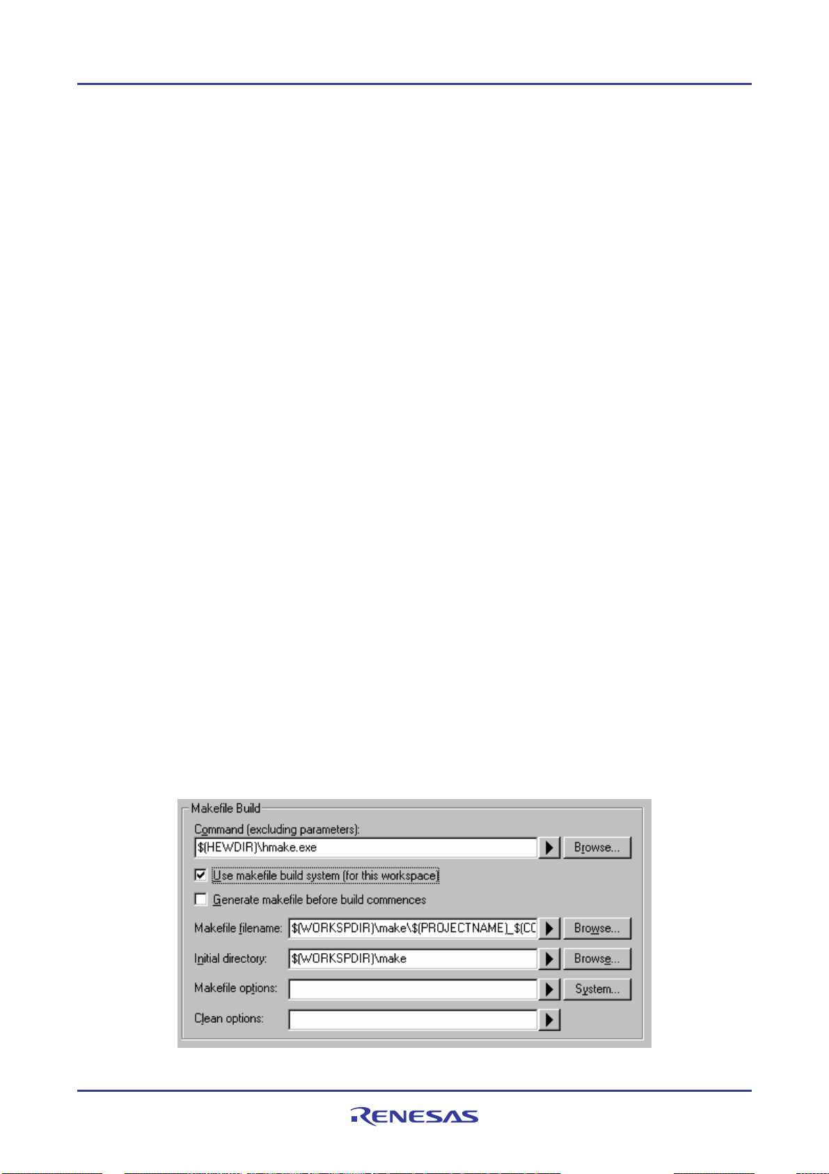
High-performance Embedded Workshop 3. Advanced Build Features
The High-performance Embedded Workshop will create a subdirectory called ’make’ within the current workspace
directory and then generate the makefile into it. The executable HMAKE.EXE, located in the High-performance
Embedded Workshop installation directory, is provided for you to execute the makefiles generated by HMake selected
in Makefile format.
If you wish to modify makefiles, see Reference 13, HMAKE User Guide.
Note:
If the name of the High-performance Embedded Workshop installation directory includes a space, the GNU Make
command may not work correctly when GNU Make is selected as the makefile format with the makefile generating
function.
To execute a makefile (HMake)
1. Open a DOS Command Prompt window and move to the ‘make’ directory where the makefile was generated.
2. Execute HMAKE. Its command line is HMAKE.EXE <makefile>.
Note:
The degree of portability of a generated makefile is entirely dependent upon how portable the project itself is. For
example, any compiler options that include full paths to an output directory or include file directory will mean that,
when given to another user with a different installation, the build will probably fail. In general use placeholders
wherever possible – using a full, specific path should be avoided when possible.
3.9 Using a makefile inside the High-performance Embedded Workshop system
The High-performance Embedded Workshop also allows you to configure the internal build to use a particular make
tool (hmake, nmake, or gmake) as well as the internal High-performance Embedded Workshop system.
The build procedures using makefiles are listed below. nmake and gmake tools must be prepared by the user, while
hmake is installed in the High-performance Embedded Workshop installation directory.
To set-up the internal makefile execution
1. Create a High-performance Embedded Workshop workspace.
2. If you want to use a High-performance Embedded Workshop generated makefile, select [Build -> Generate
Makefile] to generate a makefile. For details, see section 3.8, Generating a makefile.
3. Select [Setup -> Options]. The Options dialog box opens.
4. Click the Build tab.
REJ10J1837-0100 Rev.1.00 Nov. 16, 2008
81
Page 97

High-performance Embedded Workshop 3. Advanced Build Features
5. Enter the make tool name to execute the makefile in the Command (excluding parameters) edit box. The
default is hmake ($(HEWDIR)\hmake.exe).
6. Select the Use makefile build system (for this workspace) checkbox. This means that the makefile should be
executed rather than the internal build.
7. While the Generate makefile before build commences checkbox is selected, the High-performance
Embedded Workshop will generate a makefile before executing the build. This means the makefile will always
be up to date with the High-performance Embedded Workshop project system.
8. Enter the file name in the Makefile filename edit box. The default file name is
“$(WORKSPDIR)\make\$(PROJECTNAME)_$(CONFIGNAME).mak”.
Note: This entry can be left empty if no makefile needs to be specified on the command line.
9. In the Initial directory edit box, enter the current directory where the makefile is to be executed. When this
edit box is empty, the initial directory will default to “$(WORKSPDIR)”.
10. Enter the options for building the makefile in the Makefile options edit box.
11. Enter the options for cleaning the makefile in the Clean options edit box.
12. Click on the OK button.
Once this system is setup the build button, menu and keyboard shortcuts are linked to the makefile tool execution. The
clean all projects button, menu and keyboard shortcut will also be linked to the makefile execution . All output is
directed to the Build tab of the output window as in the case of the normal build. If you are using a build phase
supported by High-performance Embedded Workshop the line of an error message can be double-clicked to jump to the
source files. The help link should also be supported. Note when using the HMAKE.exe system the Build All toolbar
button (
) will pass a command to HMAKE to force a re-build all operation.
To set-up the makefile system environment
By default, the makefile will be executed in the default system environment (the same environment used within Highperformance Embedded Workshop). If this is not desirable, the environment can be configured as described below:
1. In the Build tab, click the System button to the right of the Makefile options controls. This will launch the
Makefile System Environment dialog box:
2. The Inherit system environment checkbox can be used to alter the inheritance of the system environment:
Set: The makefile will be executed in the standard environment. (Default.)
Clear: The makefile will be executed in a fresh environment.
Note:
Only the "SystemRoot" variable will be carried over into the new environment as it is needed to allow program
to run in Windows®.
3. In both cases, additional environment variable can be set using the Environment variables controls. Any
values set here will override the value in the current system environment.
4. Click OK to save the changes, and return to the Options dialog box. Values will not be committed to the
Workspace until the OK button in that dialog is also used.
REJ10J1837-0100 Rev.1.00 Nov. 16, 2008
82
Page 98

High-performance Embedded Workshop 3. Advanced Build Features
3.10 Customizing the High-performance Embedded Workshop linkage order
Modules are usually linked in the alphabetical order in High-performance Embedded Workshop. However, you can
specify the linkage order if you wish to.
Note:
When the SuperH or H8SX, H8S, and H8 family toolchain is in use, the Object order list box shows library files along
with object files. However, only object files matter to the linkage order. The order of library files is only used in
searching for undefined symbols.
To manually change the linkage order
1. Click [Build -> Linkage Order]. The Linkage Order dialog box opens.
2. Select the Use custom linkage order check box.
3. The Object order list box allows you to specify the linkage order of modules. Each module has a different
icon depending on where it originated from. This is shown below:
You can change the linkage order in the following ways.
• To move a single or consecutive modules
Move to top
Move up
Moves the selected module(s) to the top.
Switches the selected module(s) and the
previous module.
REJ10J1837-0100 Rev.1.00 Nov. 16, 2008
83
Page 99

High-performance Embedded Workshop 3. Advanced Build Features
Move down
Switches the selected module(s) and the
next module.
Move to bottom
Moves the selected module(s) to the
bottom.
• To move non-consecutive modules
Move to top
Moves all of the selected modules to the
top.
Group up
Moves all of the selected modules to the
position of the first one among them.
Group down
Moves all of the selected modules to the
position of the last one among them.
Move to bottom
Moves all of the selected modules to the
bottom.
If the top module is selected, the Move to top and Move up buttons will be disabled. If the bottom module is
selected, the Move to bottom and Move down buttons will be disabled.
The current linkage order can be saved in a text format. You can modify the linkage order saved in the file and load it to
apply the new linkage order.
To load the linkage order from a text file
1. Click [Build -> Linkage Order]. The Linkage Order dialog box opens.
2. Select the Use custom linkage order check box.
3. Click on the Import button. The Import Linkage Order dialog box opens.
4. Choose a file and click on the Select button. The Linkage Order Import Report dialog box opens.
5. To load the linkage order saved in the file, click on the Continue button. The listbox will be updated with the
new linkage order.
Note: This will overwrite your current linkage order.
6. Click on the Cancel button to close the dialog box without modifying your current linkage order.
REJ10J1837-0100 Rev.1.00 Nov. 16, 2008
84
Page 100

High-performance Embedded Workshop 3. Advanced Build Features
To save the linkage order in a text file
1. Click [Build -> Linkage Order]. The Linkage Order dialog box opens.
2. Select the Use custom linkage order check box.
3. Click on the Export button. The Export Linkage Order dialog box opens.
4. Choose a file and directory and click on the Save button. The current settings in the list box are saved in the
specified text file.
Example:
# Exported linkage order for project "Project_name" - configuration "Debug"
c:\workspace\workspace_name\project_name\debug\main.obj
c:\workspace\workspace_name\project_name\debug\resetprg.obj
c:\workspace\workspace_name\project_name\debug\intprg.obj
c:\workspace\workspace_name\project_name\debug\runtime_library.lib
c:\workspace\workspace_name\project_name\debug\projectname.lib
c:\workspace\workspace_name\project_name\debug\user_edit_options.lib
Open the file (e.g. in the Editor), modify the linkage order, and then save it in the text format. Follow the
procedures of “To import the linkage order from the text file” to load the new linkage order.
When you are using multiple configurations it is likely that the linkage order will be very similar. To do this effectively
you can copy the current settings in the dialog to other configurations. This is described below:
To copy the linkage order from one configuration to another
1. Click [Build -> Linkage Order]. The Linkage Order dialog box opens.
2. Select the Use custom linkage order check box.
3. Select the configuration you wish to copy in the Current configuration drop-down list. This defaults to the
currently loaded configuration.
4. Click the Copy to button this displays the Select Configuration To Copy To dialog box and asks you which
of the configurations in the current project you wish to copy the current linkage order to.
5. Select a configuration and click OK.
REJ10J1837-0100 Rev.1.00 Nov. 16, 2008
85
 Loading...