


Application Note
R01AN5310EJ0100 Rev.1.00 Page1 of 129
Mar. 15, 2021
RE01B Group
Getting Started Guide to Development Using CMSIS Package
Summary
This application note describes the procedure for developing software using the CMSIS Driver Package for
the RE01B Group. This startup guide will help you understand the basic usage of the driver provided in the
package and how to develop application programs for peripheral functions not supported by the package.
Target Device
• RE01B Group
When using this application note with other Renesas MCUs, careful evaluation is recommended after making
modifications to comply with the alternate MCU.
R01AN5310EJ0100
Rev.1.00
Mar. 15, 2021
✓ The RE01B Group CMSIS package combines the startup code and peripheral function drivers of
the RE01B Group
✓ Chapter 2 describes an overview of the development environment.
✓ Chapter 3 provides an overview of the drivers.
✓ Chapter 4 explains the components and drivers.
✓ Chapter 5 explains basic functions (interrupts, pin settings, etc.).
✓ Chapter 6 explains how to create a user program.
✓ Chapter 7 explains how to create a project.
✓ Chapter 8 explains debugging.
Summary

RE01B Group Getting Started Guide to Development Using CMSIS Package
R01AN5310EJ0100 Rev.1.00 Page 2 of 129
Mar. 15, 2021
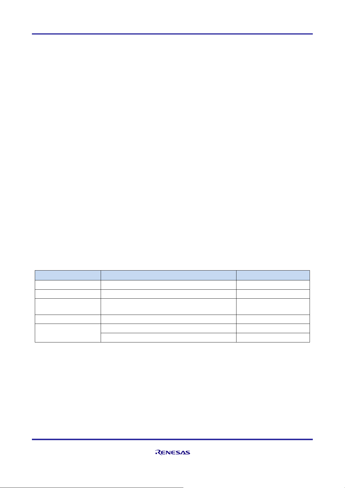
List of Terms
Terms
Description
Address mapping
Assignment of programs and data to specific areas in the MCU’s on-chip memory space
(address space)
Callback function
A function, created by the user, that is called by a driver when a specific event occurs
CMSIS
A software interface standard specified by Arm®. CMSIS stands for Cortex® Microcontroller
Software Interface Standard.
CMSIS-CORE
An MCU startup routine conforming to CMSIS
CMSIS-Driver
A peripheral function driver for a software interface conforming to CMSIS
Doxygen
A documentation generator. When comments are written in the source code in the format
specified by Doxygen, reference documentation is automatically generated from the source
code by Doxygen. (CMSIS provides documentation such as function specifications
generated from the code in HTML format using Doxygen.)
Driver HAL
A driver with specifications exclusive to an MCU vendor (Renesas in the case of this
document)
EWARM
The integrated development environment (IDE) provided by IAR Systems
(EWARM: IAR Embedded Workbench® for Arm®)
ICU
RE01B interrupt controller unit
IRQ number
NVIC external interrupt input number
MTB
MTB (Micro Trace Buffer): Instruction trace method that uses a part of SRAM provided as
an option for CortexM0+
NVIC
Nested vector interrupt controller mounted on Arm Cortex-M0 + etc.
R_CORE
Specifications exclusive to Renesas added to CMSIS-CORE
R_SYSTEM
Drivers exclusive to Renesas for clock switching, interrupt control, etc.
Startup
Activation processing from when the MCU is reset to the jump to the Main function
User’s manual
The MCU manual, available from Renesas

RE01B Group Getting Started Guide to Development Using CMSIS Package
R01AN5310EJ0100 Rev.1.00 Page 3 of 129
Mar. 15, 2021
Table of Contents
1. Package Summary .................................................................................................................... 6
1.1 About this document ................................................................................................................................ 6
1.2 About CMSIS ........................................................................................................................................... 6
1.3 Folder Structure ....................................................................................................................................... 8
1.4 Supported Functions ............................................................................................................................... 9
1.5 Package Features ................................................................................................................................. 10
1.6 Operation Confirmation Environment .................................................................................................... 10
2. Setting up the Development Environment ............................................................................... 12
2.1 Overview of the Project in this Package ................................................................................................ 12
2.2 Debug Environment Using EWARM ..................................................................................................... 13
2.3 e2 studio Version ................................................................................................................................... 20
3. Driver Overview ....................................................................................................................... 23
3.1 Three Types of Files Comprising the Drivers ........................................................................................ 23
3.2 Notation of Driver Name ........................................................................................................................ 23
3.3 Storage Location of Driver-related Files ................................................................................................ 24
3.4 Storage Location of Driver Specifications ............................................................................................. 25
3.4.1 Driver Specifications (PDF Format) .................................................................................................... 25
3.4.2 CMSIS-DSP Library Document (Doxygen Format) ............................................................................. 25
4. Components and Drivers ......................................................................................................... 27
4.1 Drivers Provided by Each Component .................................................................................................. 27
4.2 Common Function Drivers ..................................................................................................................... 29
4.2.1 R_CORE Driver ................................................................................................................................... 29
4.2.2 R_SYSTEM Driver .............................................................................................................................. 30
4.2.3 R_PIN Driver ....................................................................................................................................... 30
4.2.4 R_LPM Driver ...................................................................................................................................... 31
4.3 Peripheral Function Drivers ................................................................................................................... 32
4.3.1 Peripheral Function Drivers (CMSIS-Drive) ........................................................................................ 32
4.3.2 Peripheral Function Drivers (Drive HAL) ............................................................................................. 34
4.4 CMSIS-DSP Component ....................................................................................................................... 36
4.4.1 How to Get DSP Library and Import Procedure to Project .................................................................. 36
5. Basic Functions ....................................................................................................................... 44
5.1 Startup Processing ................................................................................................................................ 44
5.1.1 Pin Settings at Operation Start ............................................................................................................ 46
5.1.2 Clock and Power Control Mode Settings at Start of Operation ........................................................... 47
5.2 Control of Undefined Value Propagation Suppression Function ........................................................... 49
5.2.1 Applicable Power Supply Domains ..................................................................................................... 49

RE01B Group Getting Started Guide to Development Using CMSIS Package
R01AN5310EJ0100 Rev.1.00 Page 4 of 129
Mar. 15, 2021
5.2.2 Driver Functions .................................................................................................................................. 49
5.3 Interrupt Control..................................................................................................................................... 51
5.3.1 Interrupt Vector Table and Entry Functions ........................................................................................ 51
5.3.2 Overview of Interrupt Handling of Peripheral Functions ..................................................................... 52
5.3.3 IRQ Number Allocation ........................................................................................................................ 52
5.3.4 Editing r_system_cfg.h ........................................................................................................................ 54
5.3.5 Processing Related to Interrupts in User Application .......................................................................... 55
5.4 Clock Settings ........................................................................................................................................ 57
5.4.1 Clock Definitions .................................................................................................................................. 57
5.4.2 Driver Functions .................................................................................................................................. 58
5.5 Pin Settings ........................................................................................................................................... 59
5.5.1 Editing pin.c File in Initial Settings ....................................................................................................... 59
5.5.2 Pin Settings in User Application .......................................................................................................... 59
5.5.3 R_Pin Driver Functions ....................................................................................................................... 60
5.5.4 Edit R_PIN Driver Function ................................................................................................................. 61
5.6 Program RAM Placement ...................................................................................................................... 62
5.6.1 RAM Placement Method Using RAM Placement Section ................................................................... 63
5.6.2 Method of RAM Placement Using Forced Inline Expansion ............................................................... 68
6. Creating a User Program ......................................................................................................... 69
6.1 Preparation for User Program Creation ................................................................................................ 69
6.1.1 Preparation for Startup Processing ..................................................................................................... 71
6.1.2 Preparation of Common Function Drivers ........................................................................................... 73
6.1.3 Preparation of Peripheral Function Drivers ......................................................................................... 77
6.2 User Program Creation ......................................................................................................................... 77
6.2.1 Initial Settings ...................................................................................................................................... 79
6.2.2 Control of Peripheral Functions ........................................................................................................... 81
6.2.3 Control of Pins ..................................................................................................................................... 88
6.2.4 Controlling Interrupts ........................................................................................................................... 89
6.3 User Program Creation Example .......................................................................................................... 90
6.3.1 Example of Using a Peripheral Function Driver (USART Communication by SCI) ............................ 90
6.3.2 Example When Peripheral Function Driver is not Used (AGT Asynchronous General-purpose Timer
Application) .......................................................................................................................................... 96
7. Creating a Project .................................................................................................................. 100
7.1 EWARM Version.................................................................................................................................. 100
7.1.1 Setting Target Processor ................................................................................................................... 101
7.1.2 Linker File Setting .............................................................................................................................. 102
7.1.3 Compiler Include Path Settings ......................................................................................................... 103
7.2 e2 studio Version ................................................................................................................................. 104
7.2.1 Setting Toolchain ............................................................................................................................... 104

RE01B Group Getting Started Guide to Development Using CMSIS Package
R01AN5310EJ0100 Rev.1.00 Page 5 of 129
Mar. 15, 2021
7.2.2 Linker File Settings ............................................................................................................................ 105
7.2.3 Include Path Settings ........................................................................................................................ 106
8. Using Debugger for Downloading .......................................................................................... 107
8.1 EWARM Version.................................................................................................................................. 107
8.1.1 J-Link ................................................................................................................................................. 107
8.1.2 I-Jet .................................................................................................................................................... 109
8.2 e2 studio Version ................................................................................................................................. 110
8.2.1 J-Link ................................................................................................................................................. 110
8.3 Securing MTB Region for Debugger ................................................................................................... 114
8.4 Settings when Using Low Power Consumption Mode ........................................................................ 115
8.5 Prohibition of Software Break Setting in the Built-in Flash Memory Area ........................................... 116
8.6 Precautions when Setting a Software Break in the Built-in Flash Memory ......................................... 117
9. Appendix ................................................................................................................................ 118
9.1 List of Interrupts Used by Peripheral Function Drivers........................................................................ 118
9.2 Reference Information: Using printf Function in Operation Confirmation Environment ...................... 119
10. Troubleshooting ..................................................................................................................... 121
10.1 Q: A build error occurs ...................................................................................................................... 121
10.2 Q: When a driver function is executed, a HardFault Error occurs .................................................... 121
10.3 Q: A driver function is being executed, but the peripheral function does not run ............................. 121
10.4 Q: The return value of a driver function is normal, but the expected input or output from a peripheral
function pin cannot be confirmed ........................................................................................................ 122
10.5 Q: Writing to a peripheral function related register was performed, but does not take effect .......... 122
10.6 Q: Writing to clock and power consumption reduction function related registers was performed, but
does not take effect ............................................................................................................................. 122
10.7 Q: The debugger cannot be used to download to the target board .................................................. 123
10.8 Q: The debugger is connected but it does not work ......................................................................... 123
10.9 Q: An interrupt does not occur. ........................................................................................................... 123
11. Notes on Migrating a Program between RE01 Group ........................................................... 124
11.1 Mode Transition Example .................................................................................................................... 124
11.1.1 Transition example 1: Transitioning between boost mode and low leak current mode .................... 125
11.1.2 Transition example 2: Transitioning between normal mode and software standby mode ................ 126
11.1.3 Transition example 3: Transitioning between high-speed mode and low-speed mode .................... 127
12. Reference Documents ........................................................................................................... 128
RE01B Group Getting Started Guide to Development Using CMSIS Package
R01AN5310EJ0100 Rev.1.00 Page 6 of 129
Mar. 15, 2021
1. Package Summary
1.1 About this document
This document focuses on the driver of the general-purpose microcomputer part. Please refer to “r01an5606”
for the Bluetooth part.
1.2 About CMSIS
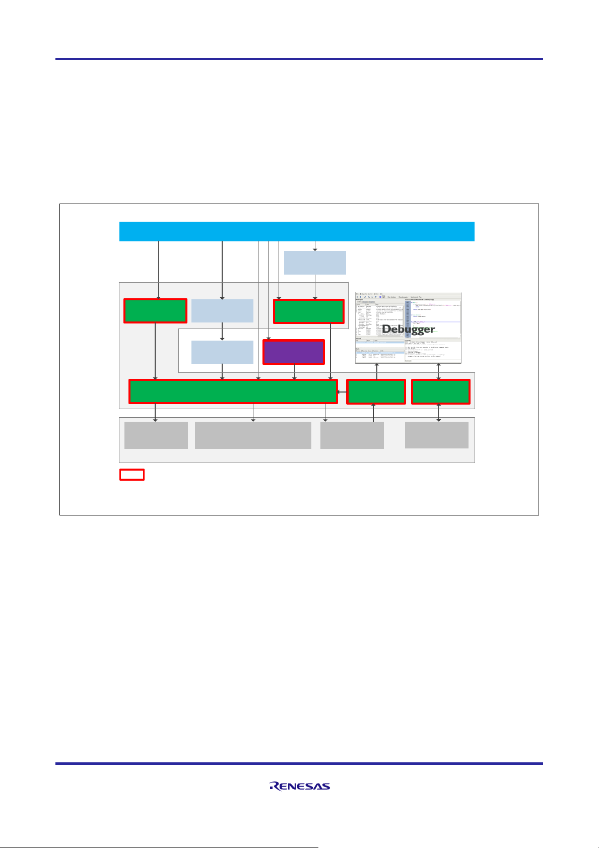
This package includes the components outlined in red in Figure 1-1.
Figure 1-1 CMSIS Overview
CMSIS Software Pack
Microcontroller
Application Code
CMSIS-DSP
CMSIS-RTOS
CMSIS-Driver
Driver HAL
RTOS Kernel
CMSIS-CORE
Processor core and peripheral access
CMSIS-SVD CMSIS-DAP
Cortex
®
CPU Core
Core
Peripherals
Other
Peripherals
CoreSight
TM
debug logic
CMSIS : Cortex® Microcontroller Software Interface Standard
SVD : System View Description
DAP : Debug Access Port
Middleware
: Components included in this package
RE01B Group Getting Started Guide to Development Using CMSIS Package
R01AN5310EJ0100 Rev.1.00 Page 7 of 129
Mar. 15, 2021
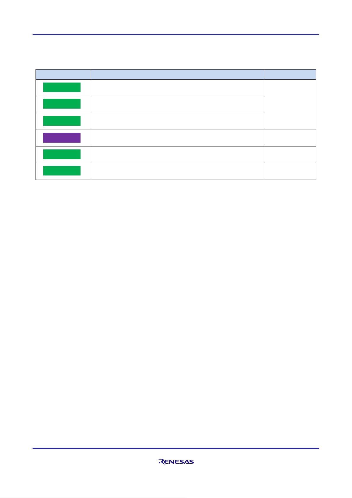
The components included in the package are shown below.
Table 1-1 Bundled Components
Component
Description
Note
Startup processing (Processing from MCU reset release to execution of
main function. Code is provided by Renesas.)
Components of
these headers are
provided by Arm®.
Driver files conforming to Arm® CMSIS standard (code and some
expansion headers are provided by Renesas.)
DSP library (Code and libraries are provided by Arm®.)
Renesas-specific drivers (peripheral function driver not standardized by
CMSIS-Driver) (HAL: Hardware Abstraction Layer)
Peripheral function register information (SVD: System View
Description)
Debugger connection information (DAP: Debug Access Port)
Driver HAL
CMSIS-SVD
CMSIS-CORE
CMSIS-Driver
CMSIS-DAP
CMSIS-DSP
RE01B Group Getting Started Guide to Development Using CMSIS Package
R01AN5310EJ0100 Rev.1.00 Page 8 of 129
Mar. 15, 2021
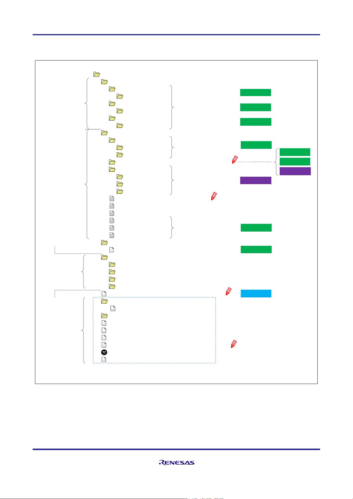
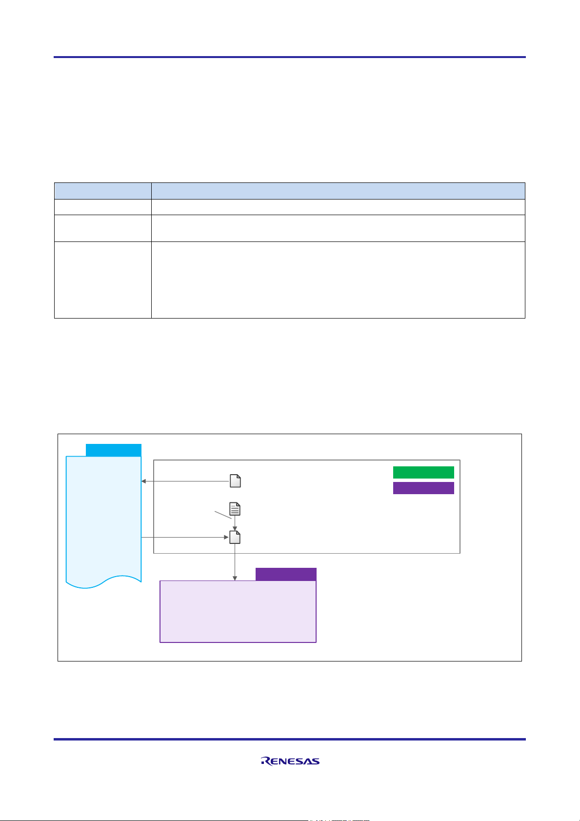
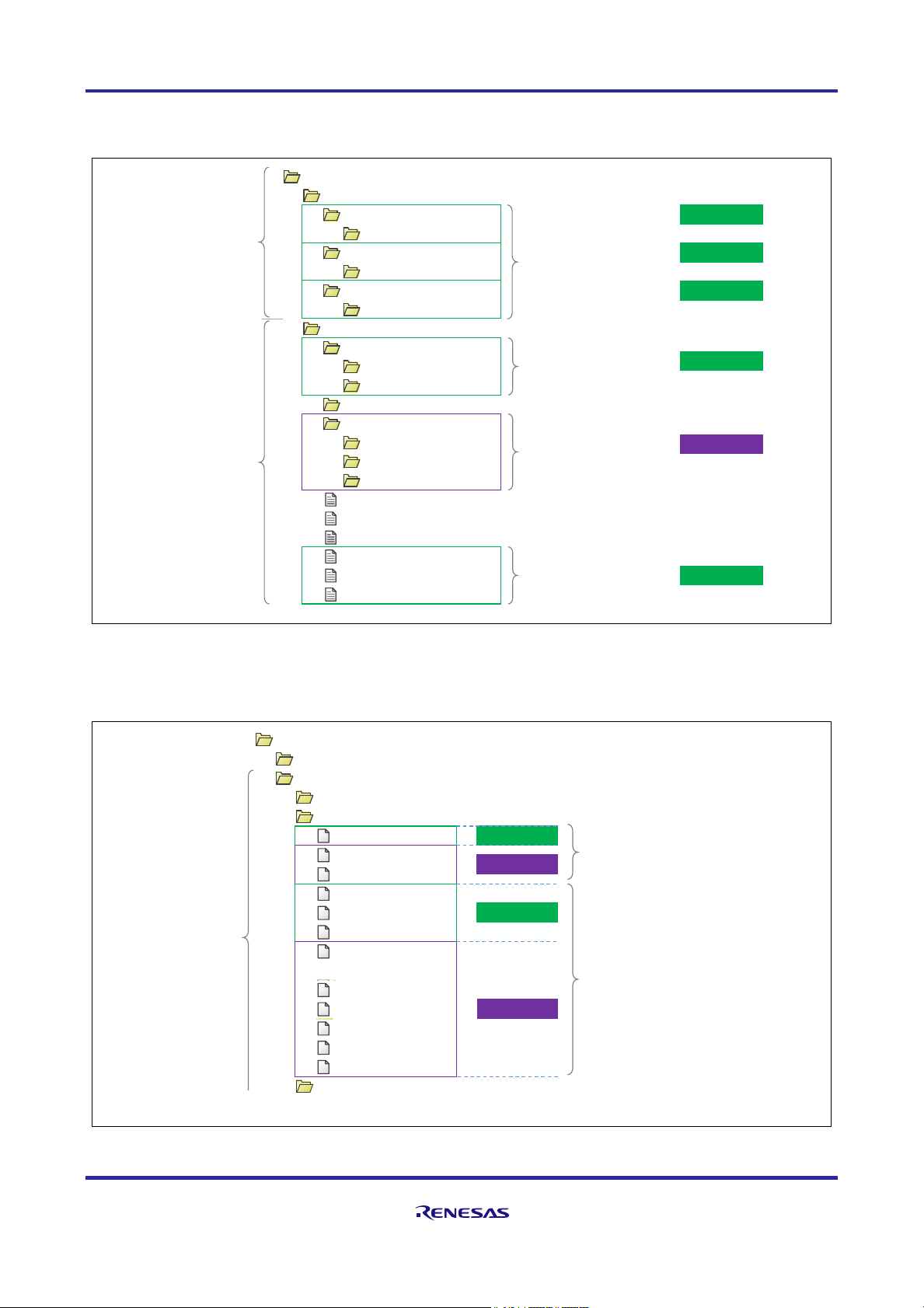
1.3 Folder Structure
The folder structure for this package is indicated in Figure 1-2.
Figure 1-2 CMSIS Driver Package Folder Structure for RE01B Group
RE01B_1500KB_DFP
├
CMSIS
│
├
Core
││└
Include
│
├
Driver
││└
Include
│
└
DSP_Lib
│
└
Include
├
Device
│
├
CMSIS_Driver
││├
Include
││└
Src
│
├
Config
………………│
├
Driver
││├
Include
││├
Lib
││└
Src
│
├
pin.c
……………
…
Pin settings file
│
├
pin.h
……………
…
Pin settings header file
│
├
RE01B_1500KB.h
………
│
├
startup_RE01B_1500KB.c
│
├
system_RE01B_1500KB.c
│
└
system_RE01B_1500KB.h
├
SVD
│
└
RE01B_1500KB.svd
…
…
├
Documents (SVD format)
│
├
Doxygen
│
├
Driver Specification
│
├
Getting_Started
│
└
License
├
main.c
…
├
config
│
└
RE01B_1500KB.icf
├
Flash Debug
├
project.dep
├
project.ewd
├
project.ewp
├
project.ewt
├
project.eww
└
RE01B_1500KB_DFP HardwareDebug.launch
Renesas original drivers
Documents
Cortex®-M0+ CPU
related files
provided by Arm®
Driver header files
Files that need to be edited
by the user
Component
Project files
User application (including startup code)
For EWARM
(IAR compiler)
▼
Register definition file
・ Startup processing
・ Interrupt vector table
▲
Driver files
Register information
Driver compliant with CMSIS
standard (including some
Renesas-specific extended
functions)
Configuration definition file
Driver files
provided by Renesas
Driver HAL
CMSIS-Driver
CMSIS-CORE
App Code
CMSIS-SVD
CMSIS-CORE
CMSIS-Driver
CMSIS-DSP
:
CMSIS-CORE
CMSIS-Driver
Driver HAL
RE01B Group Getting Started Guide to Development Using CMSIS Package
R01AN5310EJ0100 Rev.1.00 Page 9 of 129
Mar. 15, 2021
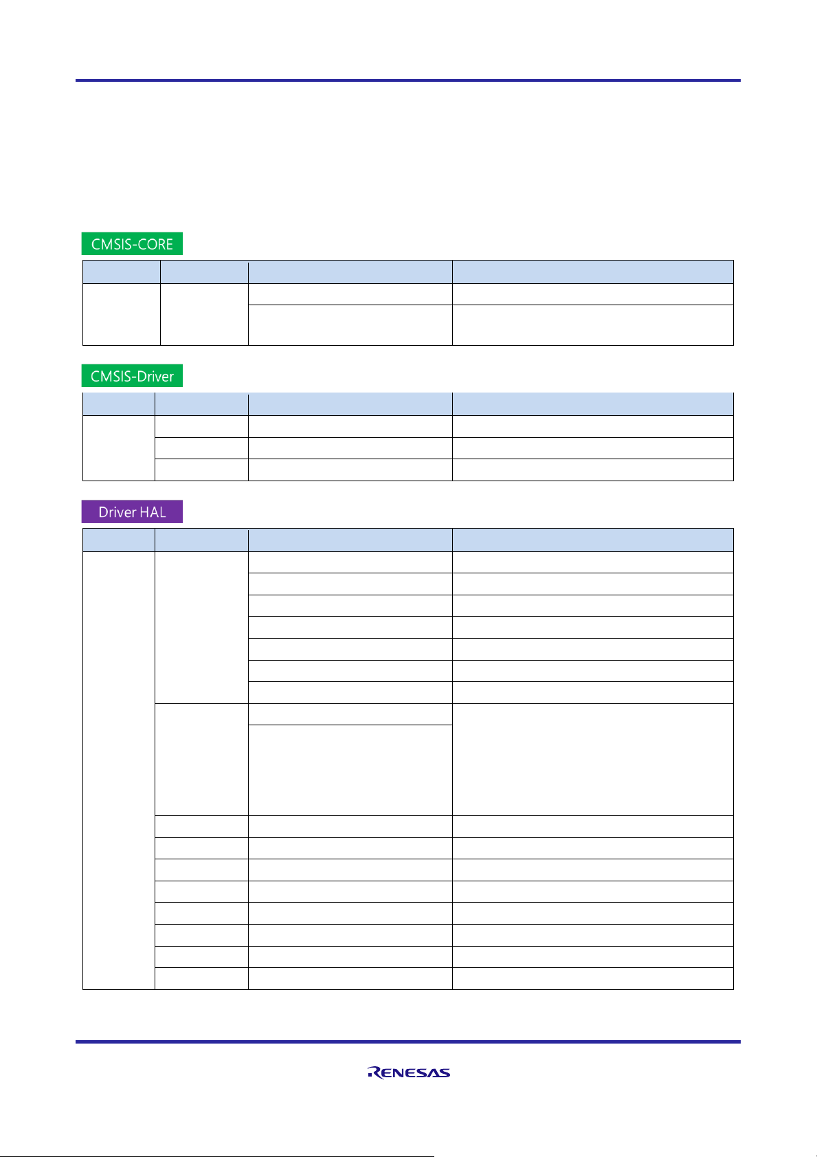
1.4 Supported Functions
The main functions supported by this package are shown below. Driver overviews are presented in chapters
3 and 4. For specifications, refer to the specification for the various drivers included in the package. (For the
storage location, refer to section 3.4, Storage Location of Driver Specifications.)
Details on peripheral functions built into the device are provided in the "User's Manual: Hardware" for each
target device.
Table 1-2 CMSIS-CORE Support Functions
Type
Driver Name
Support Function
Related Hardware Function
Common
function
driver
R_CORE
Interrupt vector table
Interrupt controller unit (ICU)
Startup processing
Clock generation circuit
Power consumption reduction function
Table 1-3 CMSIS-Driver Support Functions
Type
Driver Name
Support Function
Related Hardware Function
Peripheral
function
driver
R_SPI
SPI serial communication
Serial peripheral interface (SPI)
R_I2C
I2C serial communication
I2C bus interface (RIIC)
R_USART
UART serial communication
Serial communication interface (SCIg, SCIi)
Table 1-4 Driver HAL Support Functions
Type
Driver Name
Support Function
Related Hardware Function
Peripheral
function
driver
R_SYSTEM
Clock setting
Clock generation circuit
Power control mode
Power consumption reduction function
Option setting
Option setting memory
Interrupt control
Interrupt controller unit (ICU), NVIC*
Register write protection
Register write protection
RAM expansion of programs
(handled in software)
Hardware resource locking
(handled in software)
R_LPM
I/O power supply domain control
Power consumption reduction function
Power consumption reduction
functions
• Module stopping
• Built-in flash memory power
shutoff, etc.
R_PIN
Pin setting
Multifunction pin controller
R_ADC
14-bit A/D conversion
14-bit A/D converter
R_DMAC
DMA transfer
DMA controller (DMAC)
R_DTC
DTC transfer
Data transfer controller (DTC)
R_FLASH
On-chip flash memory
Flash memory
R_GDT
2D graphic data
2D graphic data conversion circuit (GDT)
R_SMIP
Serial MIP LCD
(handled in software)
R_BLE
BLE5.0 communication
Bluetooth low energy (BLE)
*: Refer to the chapter on NVIC in the Cortex™-M0+ Technical Reference Manual (ARM DDI 0484C).
RE01B Group Getting Started Guide to Development Using CMSIS Package
R01AN5310EJ0100 Rev.1.00 Page 10 of 129
Mar. 15, 2021
1.5 Package Features
This package provides various functions to facilitate application development. The main features of the
package are listed below.
⚫ Driver function change using the configuration definition file
Drivers in the package come with a configuration definition file (header file). By editing the definition
values in the configuration file according to the operating environment, the user can change the operating
conditions of the driver without changing the driver code itself.
For details, see chapter 3, Overview of Drivers.
⚫ Startup processing
The package provides startup processing after reset release until the main function is executed.
For details, see section 5.1, Startup Processing.
⚫ I/O power domain undefined value propagation suppression function
This device has multiple I/O power supply domains. After reset release, the undefined value propagation
suppression function is effective for all IO power domains, with some exceptions. Disable the undefined
value propagation suppression function of the IO power domain that supplies power.
For details, see section 5.2, Control of Undefined Value Propagation Suppression .
⚫ Program placement in RAM
Power consumption of the device can be reduced by shutting off the supply of power to the built-in flash
memory. When running a program expanded in RAM after shutting off the supply of power to the built-in
flash memory, it is necessary to place the desired program in RAM.
For details, see section 5.6,.Program RAM Placement.
1.6 Operation Confirmation Environment
The operation confirmation environment of the package is shown below.
Table 1-5 Operation Confirmation Environment(When using IAR Compiler)
Item
Description
Vendor
MCU
RE01B Group R7F0E01BD2DNB (LQFN64)
Renesas
Target board
EB-RE01B
TESSERA TECHNOLOGY
Integrated development
environment (IDE)
EWARM V8.50.5 or later (IAR Embedded Workbench®
for Arm®)
IAR Systems
Compiler
IAR V8.5 or later※
IAR Systems
Debugger
I-Jet
IAR Systems
J-Link
SEGGER
※A patch may need to be installed depending on the version of EWARM. If necessary, install the patch by
referring to 2.2 Debug Environment Using EWARM.

RE01B Group Getting Started Guide to Development Using CMSIS Package
R01AN5310EJ0100 Rev.1.00 Page 11 of 129
Mar. 15, 2021
Table 1-6 Operation Confirmation Environment(When using GCC Compiler)
Item
Description
Vendor
MCU
RE01B Group R7F0E01BD2DNB (LQFN64)
Renesas
Target board
EB-RE01B
TESSERA TECHNOLOGY
Integrated development
environment (IDE)
e2 studio 2021-01or later
Renesas
Compiler
GCC V.6 GNU 6-2017-q2-update
-
Debugger
J-Link
SEGGER
RE01B Group Getting Started Guide to Development Using CMSIS Package
R01AN5310EJ0100 Rev.1.00 Page 12 of 129
Mar. 15, 2021
2. Setting up the Development Environment
This chapter describes the procedure for running the project provided by the package, using the TESSERA
TECHNOLOGY EB-RE01B and SEGGER J-Link debugger as an example.
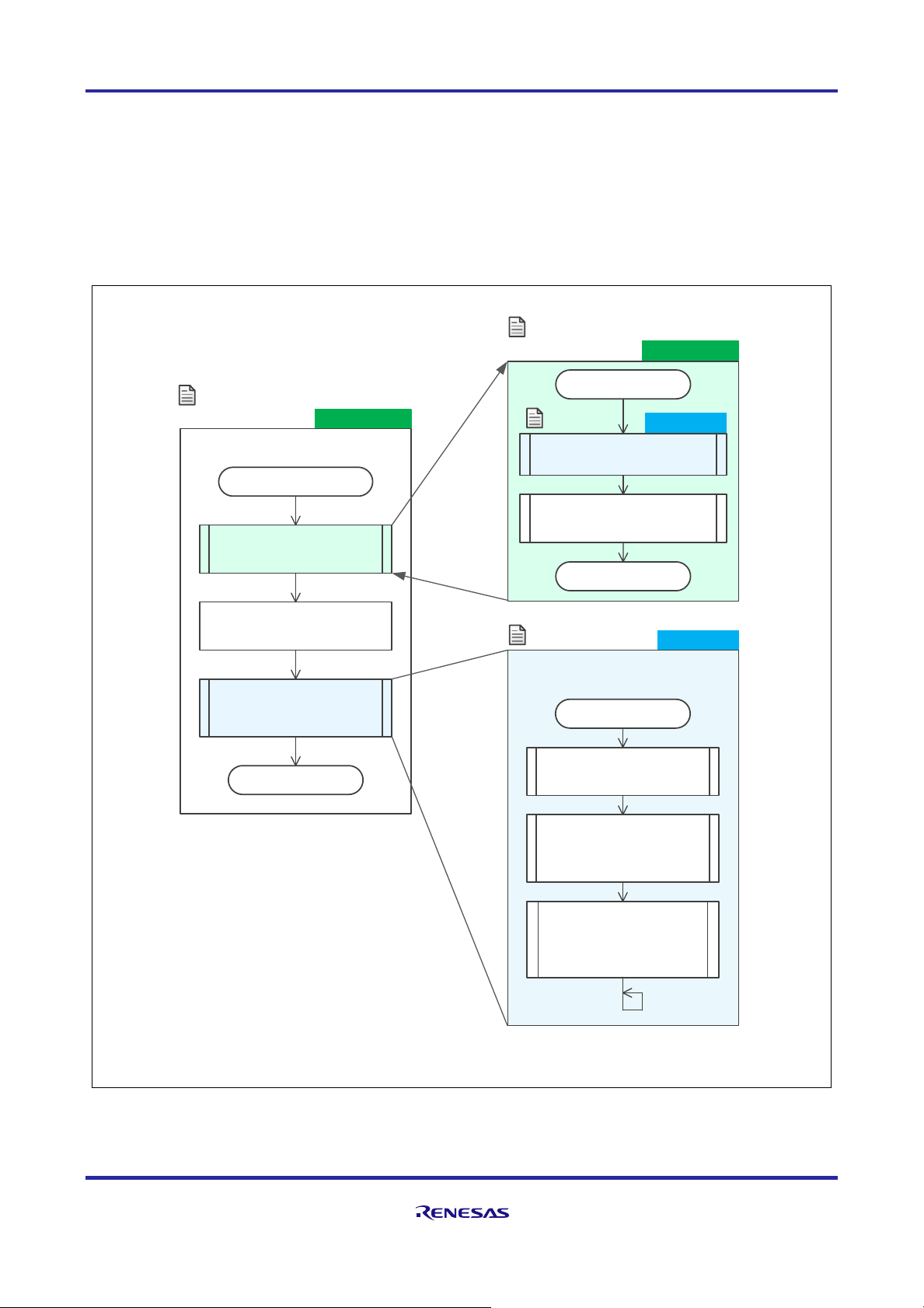
2.1 Overview of the Project in this Package
The outline of the operation flow of the sample program (main.c) included in the project of the package is
shown below. Chapters 3 to 5 explain to how to use each driver, beginning from startup.
Figure 2-1 Program Operation Flow
App Code
App Code
CMSIS-CORE
Reset_Handler function
C run time
Initialize RAM
Initialize system
(SystemInit function)
Execute user program
(main function)
End
Entry function after reset release
*1: Executed by _iar_program_start function
for IAR
(*1)
SystemInit function
Pin setting at start of operation
(BoardInit function)
Clock and power control mode
setting at start of operation
End
CMSIS-CORE
*2: R_LPM_IOPowerSupplyModeSet function
main function
Copy a program to RAM
(R_SYS_CodeCopy function)
Disable undefined value
propagation suppression
function for I/O power supply
domain (*2)
Initialize common function
drivers
(R_SYS_Initialize function)
(R_LPM_Initialize function)
User program included
in this package
startup_RE01B_1500KB.c
system_RE01B_1500KB.c
main.c
main.c
(*1)

RE01B Group Getting Started Guide to Development Using CMSIS Package
R01AN5310EJ0100 Rev.1.00 Page 13 of 129
Mar. 15, 2021
2.2 Debug Environment Using EWARM
The procedure from starting the project using EWARM to debugging is shown below. See Chapters 7 and 8
for details.
① Start up the project.
Figure 2-2 Project Startup File
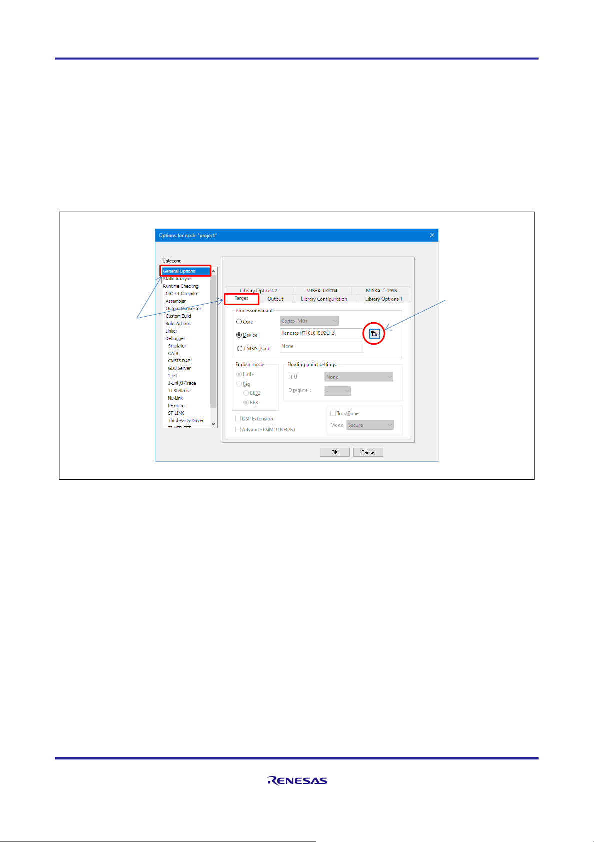
② Check if your EWARM is compatible with RE01B. If you cannot select the RE01B device, you need
to install the patch
Figure 2-3 Displaying Option Screen
├
config
│
└
RE01B_1500KB.icf
├
Flash Debug
├
project.dep
├
project.ewd
├
project.ewp
├
project.ewt
├
project.eww
└
RE01B_1500KB_DFP HardwareDebug.launch
Linker file
For EWARM
(IAR compiler)
Executable file (double-click to launch EWARM)
Select “Project” → ”Options”
RE01B Group Getting Started Guide to Development Using CMSIS Package
R01AN5310EJ0100 Rev.1.00 Page 14 of 129
Mar. 15, 2021
Confirm that R7F0E01BD2DNB is displayed according to the following.
• Device: Renesas → RE0 → RE01B_1500KB → R7F0E01BD2DNB
If R7F0E01BD2DNB does not exist, patch adaptation work is required. Please download the patch
(r20an0596) from the URL below and install it according to the attached document.
Patch download :
https://www.renesas.com/products/microcontrollers-microprocessors/re-cortex-m-ultra-low-power-sotb-
mcus/software-tools
Figure 2-4 Example of Target Processor Setting
Click here and select
the target device from
the menu
Select
“General Options”
and "Target” tab
RE01B Group Getting Started Guide to Development Using CMSIS Package
R01AN5310EJ0100 Rev.1.00 Page 15 of 129
Mar. 15, 2021
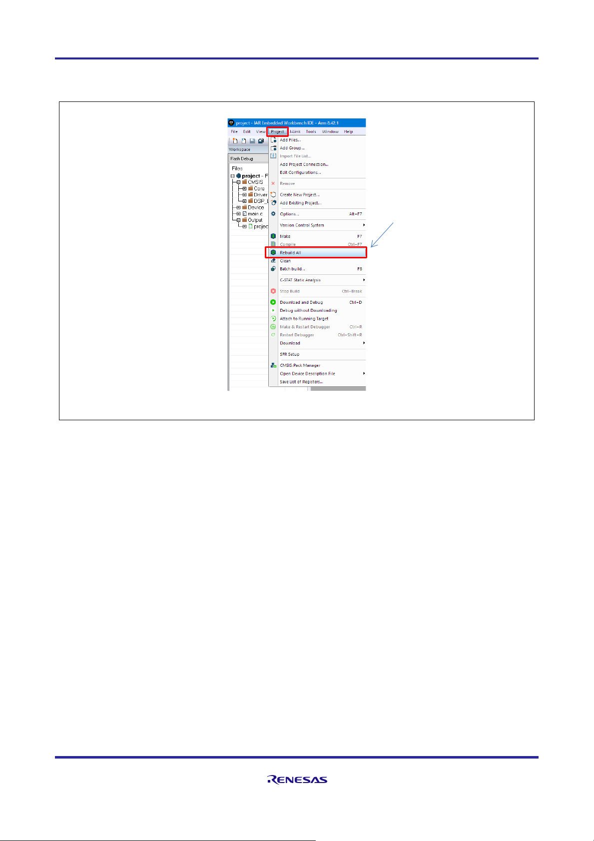
③ Compile (Project → Rebuild All).
Figure 2-5 Compile Menu
Execute "Rebuild All"
RE01B Group Getting Started Guide to Development Using CMSIS Package
R01AN5310EJ0100 Rev.1.00 Page 16 of 129
Mar. 15, 2021
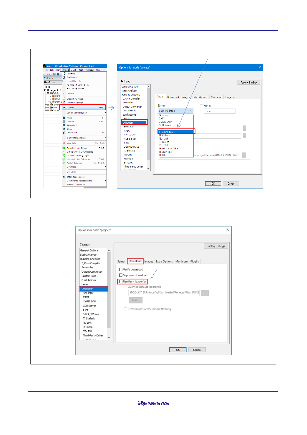
④ Select the debugger and set the options (Project → Option, Category: Debugger).
Figure 2-6 Debugger Selection
Figure 2-7 Debugger Download Options
Select J-Link/J-Trace
Uncheck "Use flash loader"
RE01B Group Getting Started Guide to Development Using CMSIS Package
R01AN5310EJ0100 Rev.1.00 Page 17 of 129
Mar. 15, 2021
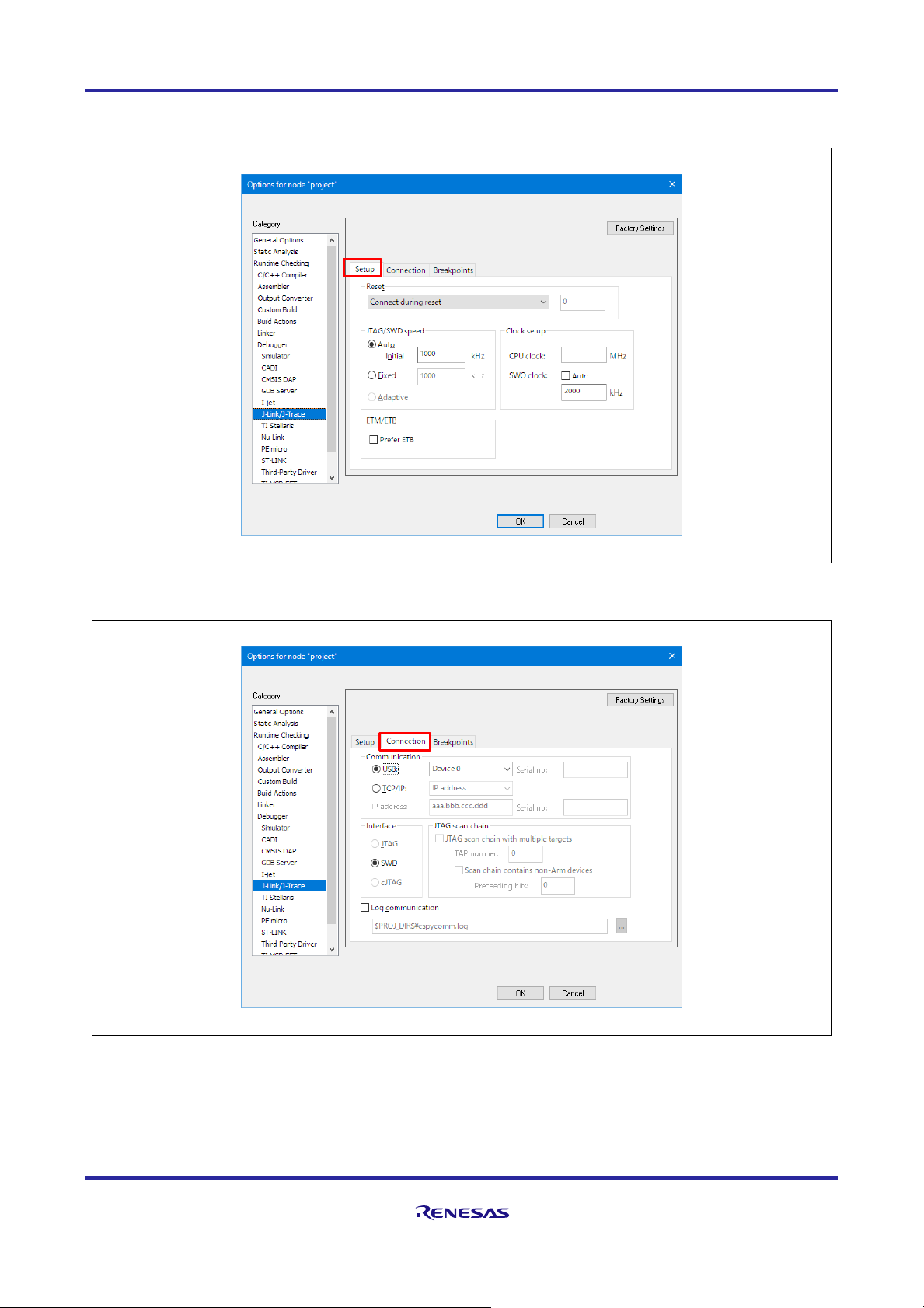
⑤ Set the J-Link/J-Trace Option settings (Category: J-Link/J-Trace).
Figure 2-8 J-Link/J-Trace Setup Options
Figure 2-9 J-Link/J-Trace Connection Options
RE01B Group Getting Started Guide to Development Using CMSIS Package
R01AN5310EJ0100 Rev.1.00 Page 18 of 129
Mar. 15, 2021
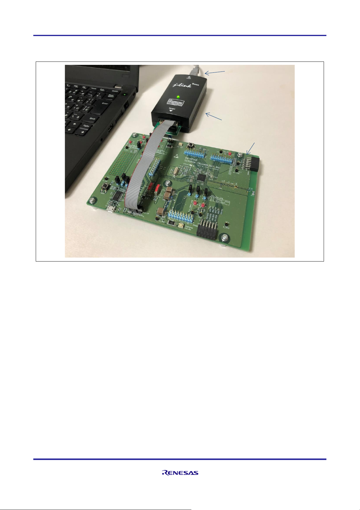
⑥ Connect the board and debugger.
Figure 2-10 Example of Connection Between Board and Debugger
USB Cable
J-Link Debugger
EB-RE01B
Emulator Connector
NOTE:
Set the power supply, jumper, etc.
in advance according to the
documentation of the evaluation board.
RE01B Group Getting Started Guide to Development Using CMSIS Package
R01AN5310EJ0100 Rev.1.00 Page 19 of 129
Mar. 15, 2021
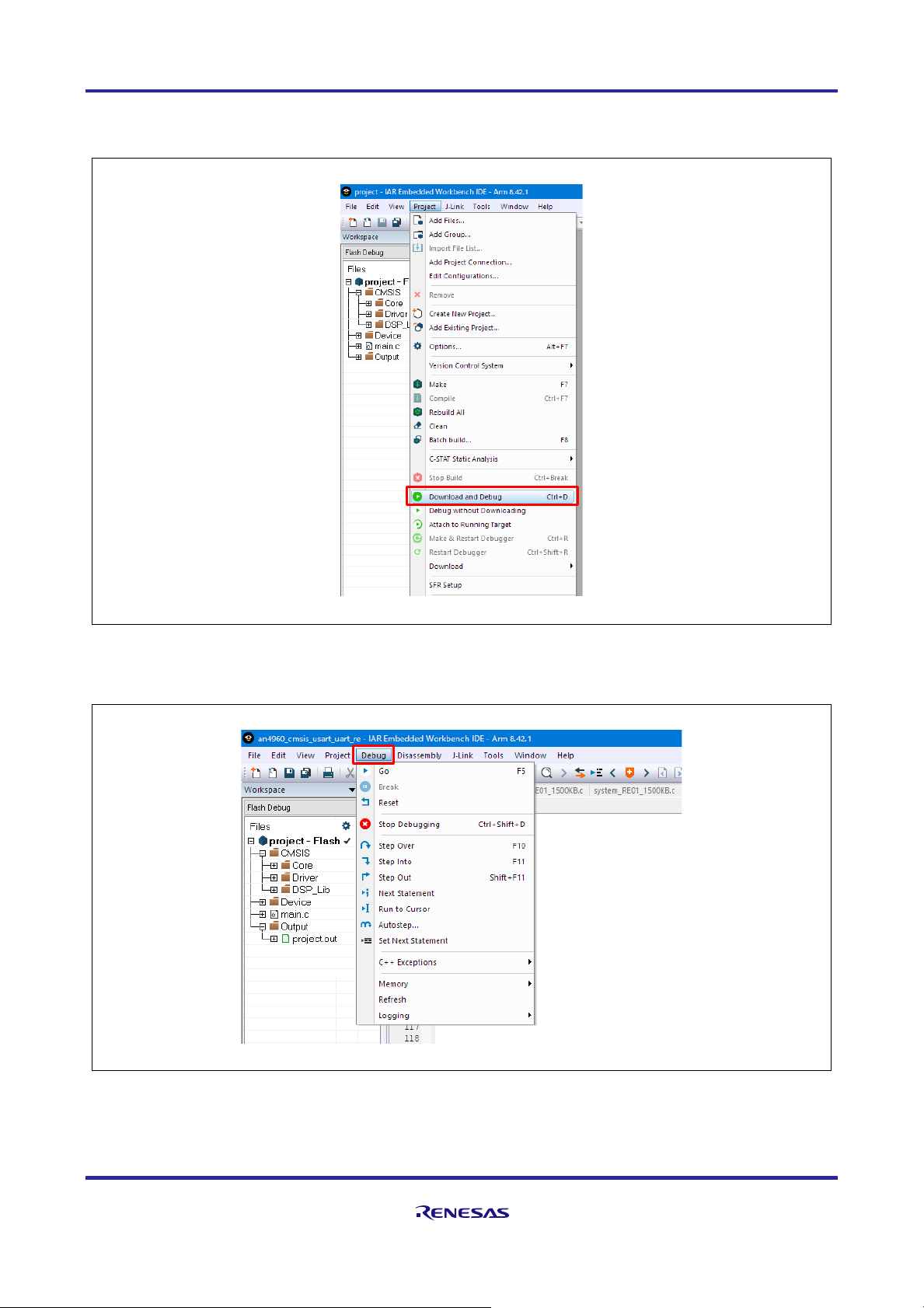
⑦ Download and start up the debugger.
Figure 2-11 Debugger Startup Menu
⑧ Once in Debug Mode, use the menu on the Debug tab to control program execution.
Figure 2-12 Program Execution Control (in Debug Mode)
RE01B Group Getting Started Guide to Development Using CMSIS Package
R01AN5310EJ0100 Rev.1.00 Page 20 of 129
Mar. 15, 2021
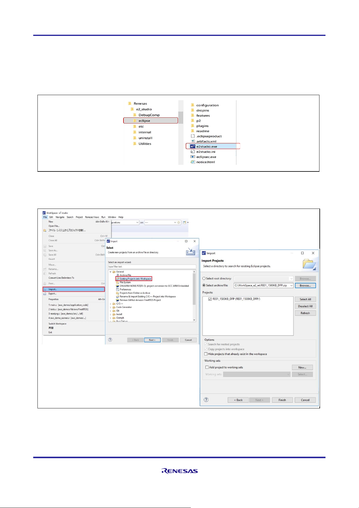
2.3 e2 studio Version
This section describes the method for running a project included with this package.
The following is an example of settings when using the Evaluation Kit board.
Start up the e2 studio
Figure 2-13 e2 studio Startup File
Perform import of a project.
Figure 2-14 Project Import Procedure
RE01B Group Getting Started Guide to Development Using CMSIS Package
R01AN5310EJ0100 Rev.1.00 Page 21 of 129
Mar. 15, 2021
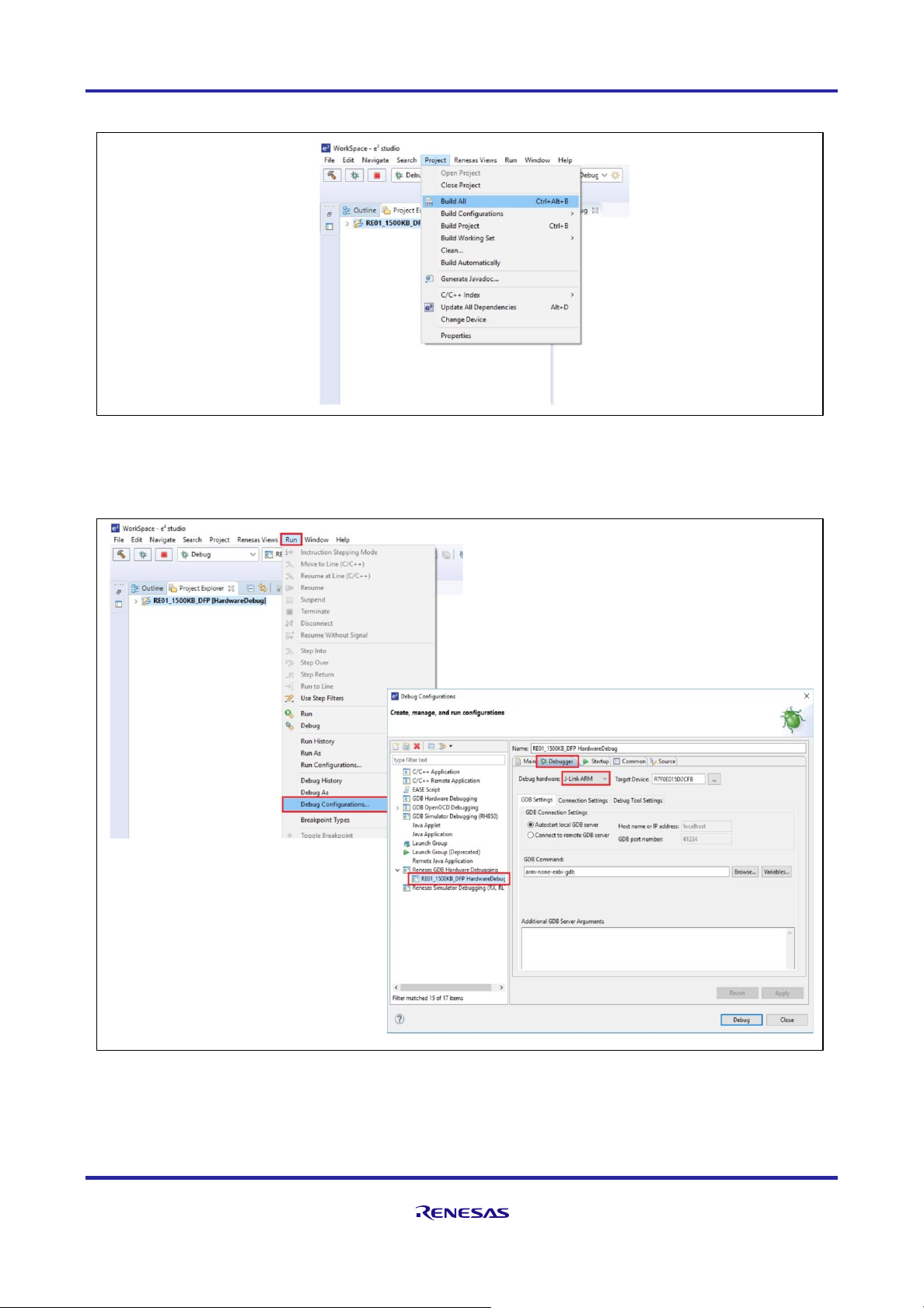
Perform compiling.
Figure 2-15 Compiler Menu
Set J-Link.
Figure 2-16 Procedure for J-Link Settings
RE01B Group Getting Started Guide to Development Using CMSIS Package
R01AN5310EJ0100 Rev.1.00 Page 22 of 129
Mar. 15, 2021
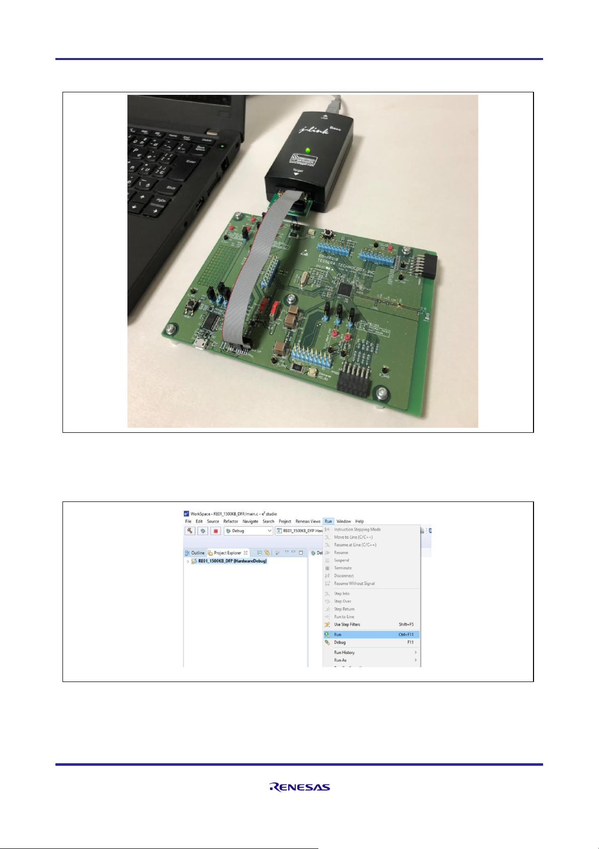
Connection with the board
Figure 2-17 Connection example
Download and start up the debugger
Figure 2-18 Debugger Startup Menu
RE01B Group Getting Started Guide to Development Using CMSIS Package
R01AN5310EJ0100 Rev.1.00 Page 23 of 129
Mar. 15, 2021
3. Driver Overview
This chapter provides an overview of the drivers included in the package.
3.1 Three Types of Files Comprising the Drivers
The drivers included in the package consist of three types of related files: the source file of the driver itself,
the include header, and the configuration definition file (with some exceptions).
Table 3-1 Driver Related Files
Filename
Description
r_***_api.c
Driver source code
r_***_api.h
• Include header for defining necessary when using the driver
• The user must include this file when using the driver.
r_***_cfg.h
• Configuration definition file defining operating conditions for the driver
• The user can edit the definition values in this file according to the operating environment.
(Driver operating conditions can be changed without modifying the driver code.)
• The user need not include this file when using the driver.
• The configuration definition header file (r_core_cfg.h) for the R_CORE driver is used in
startup processing and by the R_SYSTEM driver.
NOTE: In filenames, "***" represents the driver function name.
3.2 Notation of Driver Name
In this document, driver names written in uppercase letters (for example, R_ADC) are generic terms for
drivers that consist of three types of related files.
Figure 3-1 Driver Configuration Example
Include by user
Call driver function
Include in
driver
r_xxx_api.h: Header file
r_xxx_api.c: Driver source file
r_xxx_cfg.h: Configuration definition file
User
Application
App Code
Common function drivers
R_SYSTEM: Interrupt control function
R_PIN: Pin setting function
R_LPM: Module stop function, etc.
Driver HAL
Driver HAL
CMSIS-Driver
R_XXX Driver (Peripheral function XXX)
Example:
"R_ADC driver" is composed of the following files.
⚫ r_adc_api.h: Header file
⚫ r_adc_cfg.h: Configuration definition file
⚫ r_adc_api.c: Driver source file
RE01B Group Getting Started Guide to Development Using CMSIS Package
R01AN5310EJ0100 Rev.1.00 Page 24 of 129
Mar. 15, 2021
3.3 Storage Location of Driver-related Files
The storage locations of driver-related files are shown below. Details are described in chapter 4.
Figure 3-2 Storage Locations of Driver-related Files
The Config folder that stores the configuration definition file is shared by all of the components.
Figure 3-3 Configuration Definition Files in the Config Folder
RE01B_1500KB_DFP
├
CMSIS
│
├
Core
││└
Include
│
├
Driver
││└
Include
│
└
DSP_Lib
│
└
Include
├
Device
│
├
CMSIS_Driver
││├
Include
││└
Src
│
├
Config
……………
…
Configuration definition files (⇒ see another figure)
│
├
Driver
││├
Include
││├
Lib
││└
Src
│
├
pin.c
…………………│├
pin.h
…………………│├
RE01B_1500KB.h
…………│
├
startup_RE01B_1500KB.c
│
├
system_RE01B_1500KB.c
│
└
system_RE01B_1500KB.h
Register definition file
Drivers compliant with
CMSIS standard
Peripheral function drivers
・ Driver compliant with CMSIS
standard (including some
Renesas-specific extended
functions)
Renesas original drivers
・ Peripheral function driver
・ Common function driver
・ Startup processing
・ Interrupt vector table
Component
Cortex®-M0+ CPU
related files
provided by Arm®
Pin setting header file
Pin setting file
Driver files
provided by Renesas
CMSIS-CORE
CMSIS-Driver
CMSIS-CORE
Driver HAL
CMSIS-Driver
CMSIS-DSP
RE01B_1500KB_DFP
├
CMSIS
├
Device
│
├
CMSIS_Driver
│
├
Config
││├
r_core_cfg.h
││├
r_system_cfg.h
││├
r_lpm_cfg.h
││├
r_spi_cfg.h
││├
r_i2c_cfg.h
││├
r_usart_cfg.h
││├
r_adc_cfg.h
││├
r_ble_cfg.h
││├
r_dmac_cfg.h
││├
r_dtc_cfg.h
││├
r_flash_cfg.h
││├
r_gdt_cfg.h
││└
r_smip_cfg.h
│
├
Driver
* The order of the files has been changed for explanation.
Driver files
provided by
Renesas
Component
Peripheral function drivers
Common function drivers
CMSIS-Driver
CMSIS-CORE
Driver HAL
Driver HAL
RE01B Group Getting Started Guide to Development Using CMSIS Package
R01AN5310EJ0100 Rev.1.00 Page 25 of 129
Mar. 15, 2021
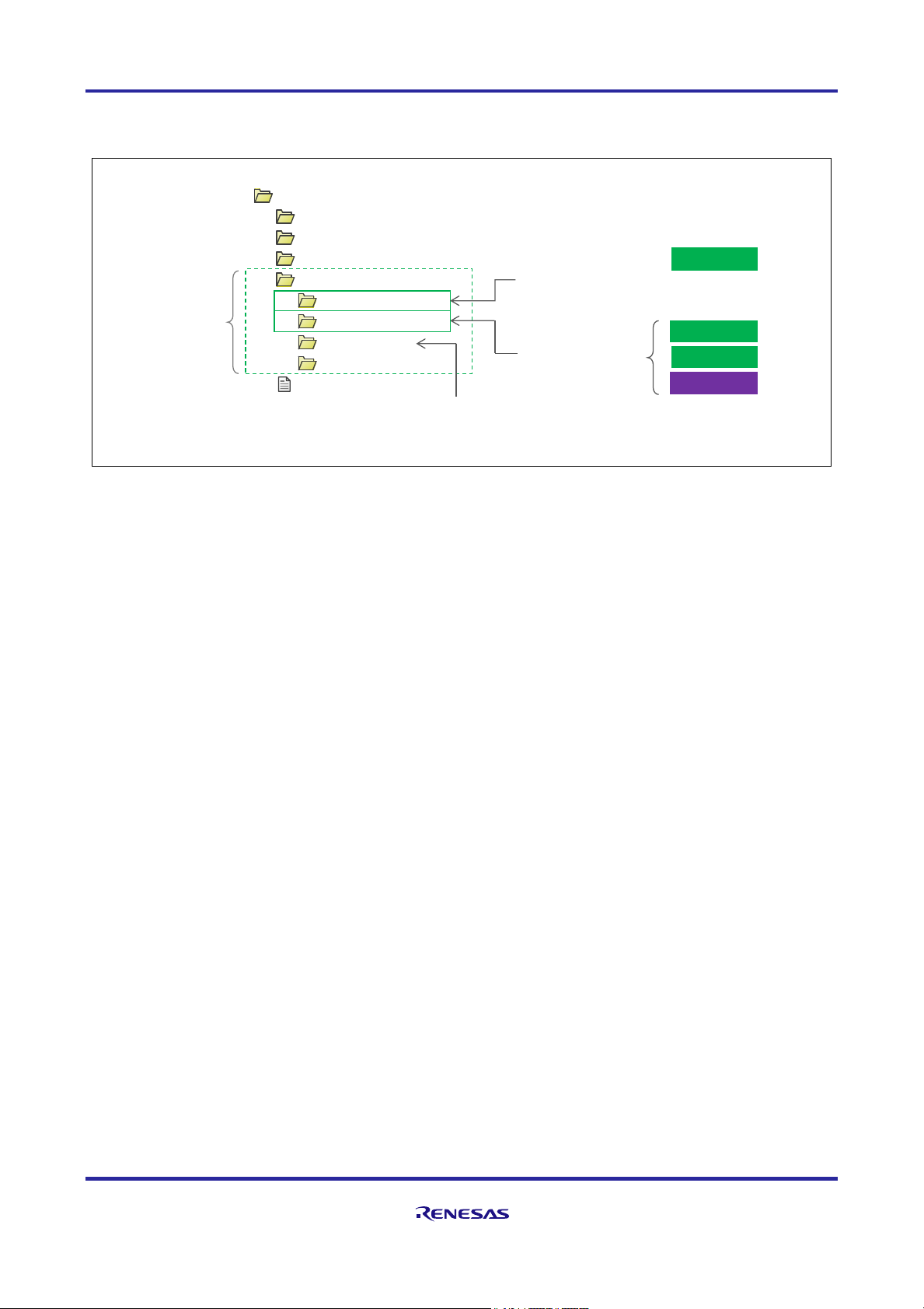
3.4 Storage Location of Driver Specifications
The package contains driver specifications. Specifications for each driver are stored in the Documents folder.
Figure 3-4 Storage Location of Driver Specifications
3.4.1 Driver Specifications (PDF Format)
Specifications for common function drivers and peripheral function drivers are provided in PDF format. These
can be found in the Driver Specification folder within the Documents folder.
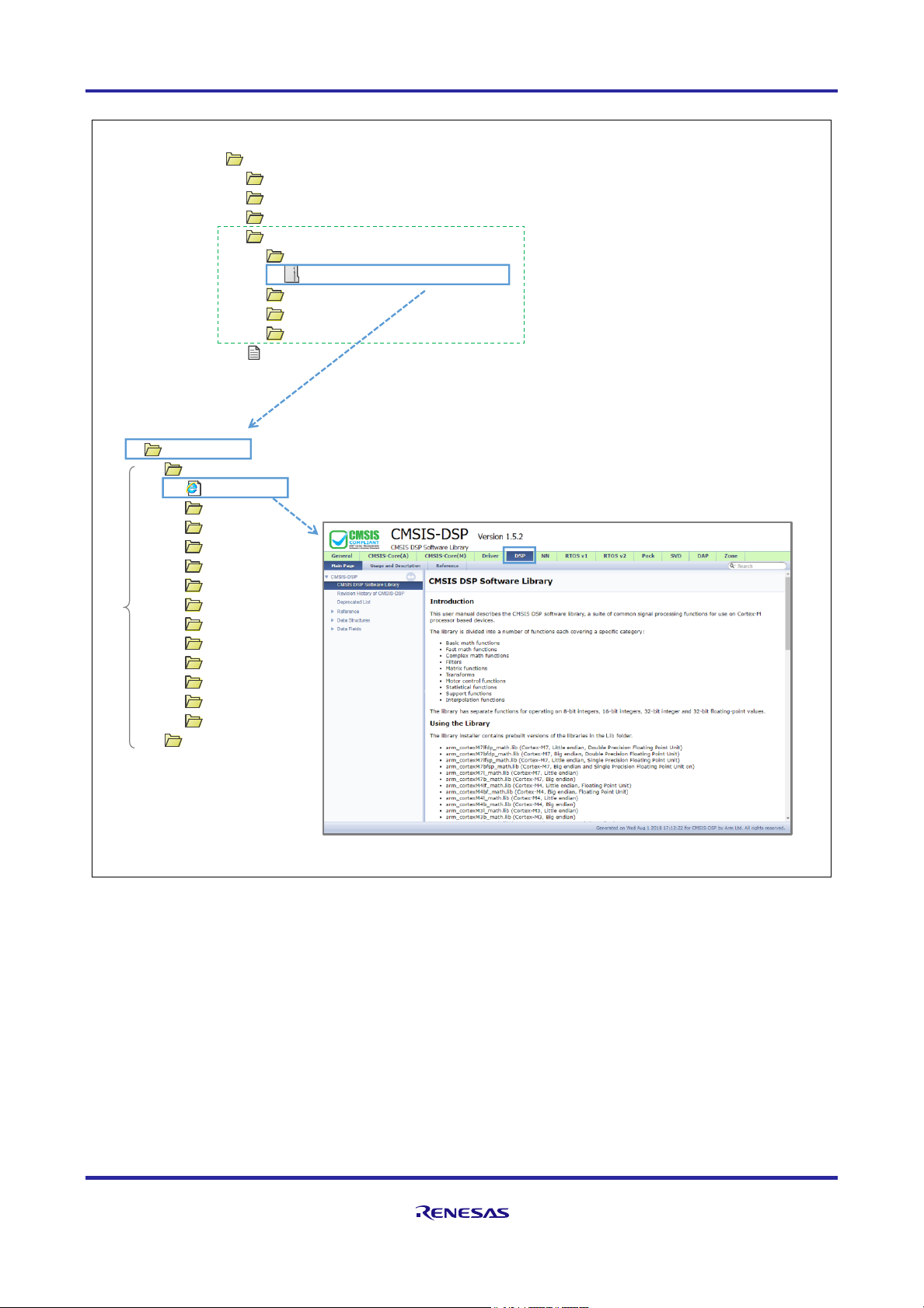
3.4.2 CMSIS-DSP Library Document (Doxygen Format)
Arm CMSIS-DSP library documentation is provided in Doxygen format. Documents are stored in the Doxygen
folder under Documents. In this package, Doxygen-related files are stored compressed, so please unzip them
before using them.
The procedure for displaying the DSP library specifications is shown in Figure 3-5.
RE01B_1500KB_DFP
├
CMSIS
├
Device
├
SVD
├
Documents
│
├
Doxygen
│
├
Driver Specification
│
├
Getting_Started
│
└
License
├
main.c
Component
CMSIS-DSP
Library documents
(Doxygen format)
Getting started guide
(this book)
Documents
Driver specifications
(PDF format)
CMSIS-CORE
CMSIS-Driver
Driver HAL
CMSIS-DSP
RE01B Group Getting Started Guide to Development Using CMSIS Package
R01AN5310EJ0100 Rev.1.00 Page 26 of 129
Mar. 15, 2021
Figure 3-5 Displaying CMSIS-DSP Library Specifications (Doxygen Format)
RE01B_1500KB_DFP
├
CMSIS
├
Device
├
SVD├Documents
│├
Doxygen
││ └
Doxygen_Please_Unzip_here.zip
│├
Driver Specification
│├
Getting_Started
│└
License
├
main.c
Doxygen
├
CMSIS_Documentation
│├
index.html
│├
Core
│├
Core_A
│├
DAP
│├
Driver
│├
DSP
│├
General
│├
NN
│├
Pack
│├
RTOS
│├
RTOS2
│├
SVD
│└
Zone
└
Vendor_Documentation
RE01B Group Getting Started Guide to Development Using CMSIS Package
R01AN5310EJ0100 Rev.1.00 Page 27 of 129
Mar. 15, 2021
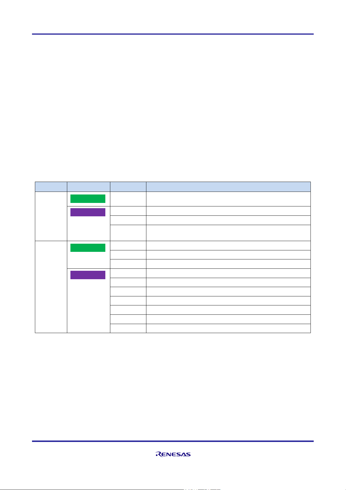
4. Components and Drivers
4.1 Drivers Provided by Each Component
There are two kinds of drivers included in the package: common function drivers and peripheral function
drivers. The relationship between components and drivers is as follows.
⑨ Common function drivers
Common function drivers are provided by two components: CMSIS-CORE and Driver HAL. The common
function driver provides functions such as interrupt management, including reset, startup processing (clock
setting, program RAM allocation, etc.), clock and power management, and interrupt and pin settings for
peripheral functions.
⑩ Peripheral function drivers
Peripheral function drivers are provided by two components: CMSIS-Driver and Driver HAL. Using these
drivers simplifies the operation of peripheral functions by the user application.
Table 4-1 Components and Drivers
Category
Component
Driver
Driver Overview
Common
Function
Drivers
R_CORE
Interrupt vector table, startup processing
R_SYSTEM
Clock setting, interrupt setting, program RAM expansion
R_PIN
Pin settings
R_LPM
IO power domain undefined value propagation suppression
function, setting the low power consumption mode
Peripheral
Function
Drivers
R_SPI
SPI serial communication
R-I2C
I2C serial communication (with Renesas-specific extensions)
R_USART
USART serial communication (with Renesas-specific extensions)
R_ADC
14-bit AD conversion
R_DMAC
DMA transfer
R_DTC
DTC transfer
R_FLASH
Built-in flash memory
R_GDT
2D graphics data conversion circuit (GDT)
R_SMIP
Serial MIP LCD
R_BLE
BLE5.0 communication
CMSIS-Driver
CMSIS-CORE
Driver HAL
Driver HAL
RE01B Group Getting Started Guide to Development Using CMSIS Package
R01AN5310EJ0100 Rev.1.00 Page 28 of 129
Mar. 15, 2021
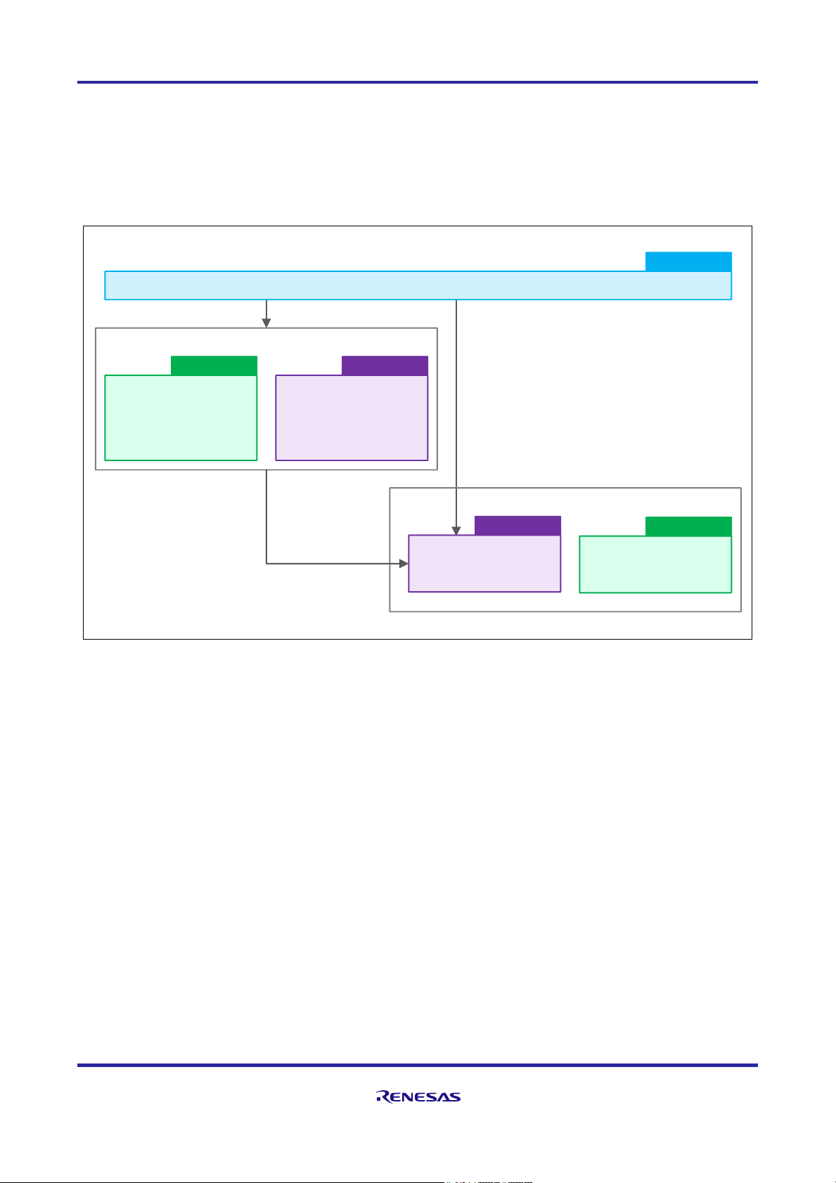
The peripheral function driver calls and executes the common function driver function from within the driver.
If a peripheral driver is not used, use the register name definition file (RE01B_1500KB.h) to directly operate
the peripheral function registers of the device. The common function driver function is also executed from the
user application.
The operation overview of the common function drivers and peripheral function drivers is shown below.
Figure 4-1 Operation Overview of Common Function Driver and Peripheral Function Driver
Peripheral function drivers
When the peripheral function driver is
not used, the user directly executes
the common function driver function
Driver HAL
Peripheral function drivers
(R_ADC, R_DMAC, R_DTC,
R_FLASH, R_GDT,
R_SMIP, R_BLE)
Driver HAL
Peripheral function drivers
(R_I2C, R_SPI, R_USAR)
CMSIS-Driver
User Application
App Code
CMSIS-CORE
Common function drivers
R_SYSTEM driver
R_PIN driver
R_LPM driver
R_CORE driver
Interrupt vector table
Startup processing

RE01B Group Getting Started Guide to Development Using CMSIS Package
R01AN5310EJ0100 Rev.1.00 Page 29 of 129
Mar. 15, 2021
4.2 Common Function Drivers
4.2.1 R_CORE Driver
R_CORE is a driver provided by the CMSIS-CORE component. The outline of the R_CORE driver is shown
below.
Table 4-2 Overview of R_CORE driver
Driver Name
Function
Description
R_CORE
Interrupt vector table
• An interrupt vector table is provided that manages entry function
addresses when reset release or an IRQ or other interrupt occurs.
• (For details, see section 5.3, Interrupt Control.)
Startup processing
• The entry function called after reset release performs startup processing
before executing the main function.
• In this package, in addition to startup defined in CMSIS-CORE, initial
settings for the operation clock and power control mode are made
according to the settings in r_core_cfg.h.
• (For details, see section 5.1, Startup Processing.)
The R_CORE driver has a configuration definition file (r_core_cfg.h) in the Config folder, and the user can
edit the definition values according to the operating environment. The files related to the R_CORE driver are
shown below.
Table 4-1 Files Related to R_CORE Driver
Driver Name
Related Files
Overview of Related Files
R_CORE
startup_RE01B_1500KB.c
R_CORE Startup source file
system_RE01B_1500KB.c
R_CORE System initialization source file
system_RE01B_1500KB.h
R_CORE System initialization header file
r_core_cfg.h
R_CORE Configuration definition file
Figure 4-2 Files Related to R_CORE Driver
RE01B_1500KB_DFP
├
CMSIS
│
├
Core
││└
Include
│
├
Driver
│
└
DSP_Lib
├
Device
│
├
CMSIS_Driver
│
├
Config
││├
r_core_cfg.h
││├
: :
│
├
Driver
│
├
pin.c
│
├
pin.h
│
├
RE01B_1500KB.h
│
├
startup_RE01B_1500KB.c
│
├
system_RE01B_1500KB.c
│
└
system_RE01B_1500KB.h
Startup processing
Component
Driver header files
Common function driver
Cortex®-M0+ CPU
related files
provided by Arm®
Driver files
provided by Renesas
Configuration definition file
CMSIS-CORE

RE01B Group Getting Started Guide to Development Using CMSIS Package
R01AN5310EJ0100 Rev.1.00 Page 30 of 129
Mar. 15, 2021
4.2.2 R_SYSTEM Driver
R_SYSTEM is a driver provided by the Driver HAL component. The outline of the R_SYSTEM driver is shown
below.
Table 4-2 Overview of R_SYSTEM Driver
Driver Name
Function Overview
R_SYSTEM
Clock settings
• Provide functions to set the clock.
• (For details, refer to 5.4 Clock Setting)
Interrupt settings
• Provide functions and definition files for interrupt control.
• (For details, Refer to 5.3 Interrupt Control)
Program expansion in
RAM area
• Provides a function to copy the program assigned to the RAM section
to the RAM area.
• For details on program RAM allocation, refer to section 5.6, Program
RAM Placement.
The R_SYSTEM driver has a configuration definition file in the Config folder, and the user can edit the
definition values according to the operating environment. The files related to the R_SYSTEM driver are shown
below. Some functions of the R_SYSTEM driver refer to the configuration file (r_core_cfg.h) of the R_CORE
driver.
Table 4-3 Files Related to R_SYSTEM Driver
Driver Name
Related Files
Overview of Related Files
R_SYSTEM
r_system_api.c
R_SYSTEM driver source file
r_system_api.h
R_SYSTEM driver header file
r_system_cfg.h
R_SYSTEM configuration definition file
4.2.3 R_PIN Driver
R_PIN is a driver provided by the Driver HAL component. The outline of the R_PIN driver is shown below.
Table 4-4 Overview of R_PIN Driver
Driver Name
Function Overview
R_PIN
Pin settings
• Functions for controlling the pins used for peripheral functions are
provided.
• (For details, refer to section 5.5, Pin Settings)
Table 4-5 Files Related to R_PIN Driver
Driver Name
Related Files
Overview of Related Files
R_PIN
pin.c
Pin setting file
pin.h
Pin setting header file

RE01B Group Getting Started Guide to Development Using CMSIS Package
R01AN5310EJ0100 Rev.1.00 Page 31 of 129
Mar. 15, 2021
4.2.4 R_LPM Driver
R_LPM is a driver provided by the Driver HAL component. The outline of the R_LPM driver is shown below.
Table 4-6 Overview of R_LPM Driver
Driver Name
Function Overview
R_LPM
Settings of the undefined
value propagation
suppression function
• A function is provided for controlling the undefined value
propagation suppression function in the IO power domain.
• (For details, refer to section 5.2 Control of Undefined Value
Propagation Suppression in I/O Power Supply Domains.)
Setting the low power
consumption mode
• Provides a function to control the low power mode.
The R_LPM driver has a configuration definition file in the Config folder, and the user can edit the definition
values according to the operating environment. The files related to the R_LPM driver are shown below.
Table 4-7 Files Related to R_LPM Driver
Driver Name
Related Files
Overview of Related Files
R_LPM
r_lpm_api.c
R_LPM driver source file
r_lpm_api.h
R_LPM driver header file
r_lpm_cfg.h
R_LPM configuration definition file
Figure 4-3 Files Related to Common Function Drivers (R_SYSTEM, R_PIN, R_LPM)
RE01B_1500KB_DFP
├
CMSIS
├
Device
│
├
CMSIS_Driver
│
├
Config
││├
r_system_cfg.h
││├
r_lpm_cfg.h
│
│:│
├
Driver
││├
Include
│││
├
r_system_api.h
│││
├
r_lpm_api.h
│││
:
││├
Lib
││└
Src
││├
r_system
│││
└
r_system_api.c
││├
r_lpm
│││
└
r_lpm_api.c
│
│:│
├
pin.c Pin settings file
│
├
pin.h Pin settings header file
Driver source files
Driver header files
Configuration definition files
Driver files
provided by Renesas
Common function driver
Component
Driver HAL

RE01B Group Getting Started Guide to Development Using CMSIS Package
R01AN5310EJ0100 Rev.1.00 Page 32 of 129
Mar. 15, 2021
4.3 Peripheral Function Drivers
The CMSIS-Driver component provides peripheral function drivers developed by Renesas in compliance with
the CMSIS standard.
4.3.1 Peripheral Function Drivers (CMSIS-Drive)
The following is an overview of the peripheral drivers provided by the CMSIS-Driver component.
Table 4-3 Overview of Peripheral Function Drivers (CMSIS-Driver)
Driver Name
Function Overview
Provision of Renesas-
specific Extended Function
R_SPI
SPI communication or clock synchronous communication by SPI
No
R_I2C
Serial communication using I2C bus interface (RIIC)
Yes
R_USART
Asynchronous and synchronous serial communication by SCI
Yes
The related file consists of the header provided by Arm, the code provided by Renesas, and some extended
headers. Each driver has a configuration definition file in the Config folder, and the user can edit the definition
values according to the operating environment.
In addition, some of the drivers in the CMSIS-Driver component have extended functions. When using a
driver that has a Renesas-specific extended function, the extended header file should be included. Because
the standard header file is included in the extension header file, it is not necessary to include the standard
header file.
Table 4-4 Files Related to Peripheral Function Driver (CMSIS-Driver)
Driver Name
Related Files
Overview of Related Files
R_SPI
Driver_SPI.h
CMSIS Driver standard header file
r_spi_cmsis_api.c
Driver source file
r_spi_cmsis_api.h
Driver header file
r_spi_cfg.h
Configuration definition file
R_I2C
Driver_I2C.h
CMSIS Driver standard header file
R_Driver_I2C.h
CMSIS Driver extended header file
r_i2c_cmsis_api.c
Driver source file
r_i2c_cmsis_api.h
Driver header file
r_i2c_cfg.h
Configuration definition file
R_USART
Driver_USART.h
CMSIS Driver standard header file
R_Driver_USART.h
CMSIS Driver extended header file
r_usart_cmsis_api.h
Driver header file
r_usart_cfg.h
Configuration definition file
(Common)
pin.c (*)
Pin settings file
pin.h (*)
Pin settings header file
*: The pin.c and pin.h files are files related to the R_PIN driver (common function driver).

RE01B Group Getting Started Guide to Development Using CMSIS Package
R01AN5310EJ0100 Rev.1.00 Page 33 of 129
Mar. 15, 2021
Figure 4-4 Files Related to Peripheral Function Driver (CMSIS-Driver)
RE01B_1500KB_DFP
├
CMSIS
│
├
Core
│
├
Driver
││└
Include
│
└
DSP_Lib
├
Device
│
├
CMSIS_Driver
││├
Include
│││
├
R_Driver_I2C.h
│││
├
R_Driver_USART.h
│││
├
r_i2c_cmsis_api.h
│││
├
r_spi_cmsis_api.h
│││
└
r_usart_cmsis_api.h
││└
Src
││├
r_i2c_cmsis_api.c
││├
r_spi_cmsis_api.c
││└
r_usart_cmsis_api.c
│
├
Config
││├
r_spi_cfg.h
││├
r_i2c_cfg.h
││├
r_usart_cfg.h
││├
: :
│
├
Driver
│
├
pin.c
│
├
pin.h
│
├
:
:
: Files to include
Driver files
provided by Renesas
Configuration definition files
Pin settings header file
Pin settings file
Cortex®-M0+ CPU
related files
provided by Arm®
Component
Driver source files
Renesas specific extension header files
CMSIS standard header files provided by Arm
Peripheral function driver
CMSIS-Driver

RE01B Group Getting Started Guide to Development Using CMSIS Package
R01AN5310EJ0100 Rev.1.00 Page 34 of 129
Mar. 15, 2021
4.3.2 Peripheral Function Drivers (Drive HAL)
The Driver HAL component provides drivers and headers developed by Renesas. An outline of the peripheral
function drivers (Driver HAL) is shown below.
Table 4-5 Overview of Peripheral Function Drivers (Driver HAL)
Driver Name
Function Overview
R_ADC
Driver for using 14-bit A/D converter (S14AD)
R_DMAC
Driver for DMA transfer
R_DTC
Driver for DTC transfer
R_FLASH
Rewriting of built-in flash memory using self-programming (*1)
R_GDT
Driver for image processing (reduction, rotation, color synthesis, etc.) using GDT
R_SMIP
Driver to control MIP-LCD (*2)
R_BLE
Bluetooth low energy (BLE) module communication driver
*1: Function to rewrite built-in flash memory during execution in single-chip mode
*2: MIP-LCD (Memory In Pixel LCD): LCD that displays still images even when there is no input
The R_LPM driver has a configuration definition file in the Config folder, and the user can edit the definition
values according to the operating environment.
For driver HAL peripheral function driver related files, refer to the specifications of each driver. As an example,
the files related to the R_ADC driver are shown below.
Table 4-6 Peripheral Function Driver (Driver HAL) Related Files (Example of R_ADC Driver)
Driver Name
Related Files
Overview of Related Files
R_ADC
r_adc_api.c
R_ADC driver source file
r_adc_api.h
R_ADC driver header file
r_adc_cfg.h
R_ADC configuration definition file
(Common)
pin.c (*)
Pin settings file
pin.h (*)
Pin settings header file
*: The pin.c and pin.h files are files related to the R_PIN driver (common function driver).

RE01B Group Getting Started Guide to Development Using CMSIS Package
R01AN5310EJ0100 Rev.1.00 Page 35 of 129
Mar. 15, 2021
Figure 4-5 Files Related to Peripheral Function Drivers (Driver HAL)
RE01B_1500KB_DFP
├
CMSIS
├
Device
│
├
CMSIS_Driver
│
├
Config
││├
r_adc_cfg.h
││├
r_ble_cfg.h
││├
r_dmac_cfg.h
││├
r_dtc_cfg.h
││├
r_flash_cfg.h
││├
r_gdt_cfg.h
││├
r_i2c_cfg.h
││├
r_spi_cfg.h
││├
r_usart_cfg.h
│
│:│
├
Driver
││├
Include
│││
├
r_adc_api.h
│││
├
r_ble_api.h
│││
├
r_dmac_api.h
│││
├
r_dma_common_api.h
│││
├
r_dtc_api.h
│││
├
r_flash_api.h
│││
├
r_flash_lowlevel.h
│││
├
r_flash_re01b_1500kb.h
│││
├
r_gdt_api.h
│││
├
r_smip_api.h
│││:││├
Lib
││└
Src
││├
r_adc
│││
└
r_adc_api.c
││├
r_ble
│││
└
r_ble_api.c
││├
r_dmac
│││
└
r_dmac_api.c
││├
r_dtc
│││
└
r_dtc_api.c
││├
r_ehc
│││
└
r_ehc.c
││├
r_flash
│││
├
r_flash_api.c
│││
└
r_flash_lowlevel.c
││├
r_gdt
│││
└
r_gdt_api.c
││├
r_smip
│││
└
r_smip_api.c
│
│
: :
│
├
pin.c
│
├
pin.h
Pin settings file
Pin settings header file
Driver files
provided by Renesas
DMAC / DTC common driver header file
Configuration definition files
Component
Driver source files
Peripheral function driver
Driver header files
Driver HAL

RE01B Group Getting Started Guide to Development Using CMSIS Package
R01AN5310EJ0100 Rev.1.00 Page 36 of 129
Mar. 15, 2021
4.4 CMSIS-DSP Component
The CMSIS-DSP is a component consisting only of headers provided by Arm.
Figure 4-6 Files Related to CMSIS-DSP
4.4.1 How to Get DSP Library and Import Procedure to Project (1) 4.5.1.1 EWARM version
The DSP library provided by Arm includes some functions with a large code size, and there is a problem in
that compiling is not possible when using the EWARM free evaluation version license (a version which limits
the code size). This problem can be solved using a library generated by compiling DSP source code within
the CMSIS package.
The following describes how to generate a library from DSP source code in the CMSIS package provided by
Arm and import it into the project.
(1) Preparation of necessary files (when using EWARM)
Download the CMSIS package provided by Arm and unpack it anywhere on your PC.
[Reference] Arm CMSIS: https://www.arm.com/ja/why-arm/technologies/cmsis
See Figure 4-7 for the location of the required files. The left side of the figure shows the CMSIS package
provided by Arm, and the right side shows the project of this package. (Replace the version of the CMSIS
package shown in the figure with the version you use.)
Double-click “arm_cortexM_math.eww” in the Arm CMSIS package to launch the project.
Confirm that "Cortex-M0" is selected for the processor in the project options, and execute
compilation. The DSP library "iar_cortexM0l_math.a" will be generated.
Copy the DSP header files "arm_common_tables.h", "arm_const_structs.h", "arm_math.h" and the
generated DSP library "iar_cortexM0l_math.a" into the project of the package.
RE01B_1500KB_DFP
├
CMSIS
│
├
Core
│
├
Driver
│
└
DSP_Lib
│
└
Include
├
Device
├
SVD
├
Documents
Component
Driver header files
Cortex®-M0+ CPU
related files
provided by Arm®
CMSIS-DSP

RE01B Group Getting Started Guide to Development Using CMSIS Package
R01AN5310EJ0100 Rev.1.00 Page 37 of 129
Mar. 15, 2021
Figure 4-7 Copying the DSP Library (for IAR Compiler)
CMSIS_5-5.6.0
├
CMSIS
│
├
Core
│
├
CoreValidation
│
├
Core_A
│
├
DAP
│
├
Documentation
│
├
DoxyGen
│
├
Driver
│
├
DSP
│
├
DSP_Lib_TestSuite
│
├
Examples
│
├
Include
│
├
arm_common_tables.h
│
├
arm_const_structs.h
│
└
arm_math.h
│
├
Lib
│
├
Projects
│
├
ARM
│
├
GCC
│
└
IAR
│
├
arm_cortexM_math.ewp
│
├
arm_cortexM_math.eww
│
├
arm_cortexM_math_Build.bat
│
├
ReleaseM0LE
│
│
├
Exe
│
│
├
iar_cortexM0l_math.a
│
│
: :
│
│
├
List
│
│
└
Ocj
│
└
settings
│ : │
├
PythonWrapper
│
└
Source
│
├
NN
│
├
Pack
│
├
RTOS
│
├
RTOS2
│
└
Utilities
├
Device
└
docs
<CMSIS package provided by Arm®>
<This package>
EWARM project
executable file
Create Lib/IAR folder in CMSIS
folder and copy library
Component
Copy header files
RE01B_1500KB_DFP
├
CMSIS
│
├
Core
│
├
Driver
│
├
DSP_Lib
││└
Include
│
└
Lib
│
└
IAR
├
Device
├
SVD
├
Documents
├
config
└
Flash Debug
CMSIS-DSP

RE01B Group Getting Started Guide to Development Using CMSIS Package
R01AN5310EJ0100 Rev.1.00 Page 38 of 129
Mar. 15, 2021
(2) Add the DSP library to EWARM to build the target files.
Figure 4-8 Addition of Build Target Files in EWARM (1/2)
① Add the "Lib / IAR" folder created under the CMSIS folder to the project group.
Add Group
Right-click on the
CMSIS folder

RE01B Group Getting Started Guide to Development Using CMSIS Package
R01AN5310EJ0100 Rev.1.00 Page 39 of 129
Mar. 15, 2021
Figure 4-9 Addition of Build Target Files in EWARM (2/2)
② Add DSP library (iar_cortexM0l_math.a) file
Select Library/Object Files
Add Files

RE01B Group Getting Started Guide to Development Using CMSIS Package
R01AN5310EJ0100 Rev.1.00 Page 40 of 129
Mar. 15, 2021
(3) Setting project options
Add the following settings in the “Preprocessor” options of the compiler.
• Add "$PROJ_DIR$¥CMSIS¥DSP_Lib¥Include" (folder path where DSP header file was stored)
to the include directories.
• Add "ARM_MATH_CM0PLUS" to the defined symbols.
Figure 4-10 shows the EWARM option setting screen.
Figure 4-10 Compiler - Preprocessor Option Settings (EWARM)

RE01B Group Getting Started Guide to Development Using CMSIS Package
R01AN5310EJ0100 Rev.1.00 Page 41 of 129
Mar. 15, 2021
(2) 4.5.1.2 e2 studio version
See Figure 4-11 for the locations of the files. In Figure 4-11, the CMSIS package provided by Arm® is on the
left, and on the right is a project in this package (RE01B_1500KB_DFP).
The version of the CMSIS package is set as 5.4.0, but this should be changed appropriately according to the
version being used.
Copy the DSP header files "arm_common_tables.h," "arm_const_structs.h" and "arm_math.h" and the DSP
library "iar_cortexM0l_math.a" into the project of this package.
Figure 4-11 DSP Library Copying (for GCC Compiler)
Copy
(header)
Copy
(Library)

RE01B Group Getting Started Guide to Development Using CMSIS Package
R01AN5310EJ0100 Rev.1.00 Page 42 of 129
Mar. 15, 2021
Make the following settings in project properties.
Add the folder path in which the DSP header files are stored to the include paths.
• Add "ARM_MATH_CM0PLUS" to the preprocessor.
• Add the DSP filename and the folder path in which the DSP library files are stored to the library.
For property settings in e2 studio, see Figure 4-12 to Figure 4-14.
Figure 4-12 e2 studio Include Path Settings

RE01B Group Getting Started Guide to Development Using CMSIS Package
R01AN5310EJ0100 Rev.1.00 Page 43 of 129
Mar. 15, 2021
Figure 4-13 Preprocessor Setting in e2 studio
Figure 4-14 Library Setting in e2 studio

RE01B Group Getting Started Guide to Development Using CMSIS Package
R01AN5310EJ0100 Rev.1.00 Page 44 of 129
Mar. 15, 2021
5. Basic Functions
This chapter describes the following basic functions provided by the package.
5.1 Startup Processing
- Pin setting at the start of operation
- Clock/power control mode setting at the start of operation
5.2 IO Power Domain Undefined Value Propagation Suppression Control
5.3 Interrupt Control
5.4 Clock Setting
5.5 Pin Settings
5.6 Program RAM Allocation
5.1 Startup Processing
When using this package, a Reset_Handler function, which is registered as an entry function after reset
release, is called. The Reset_Handler function executes startup processing before execution of the main
function.
Startup processing mainly involves the following processing:
Pin setting at the start of operation (BoardInit function)
Setting of the clock and power control mode at the start of operation (execution of the
System_clock_init function based on the definition of r_core_cfg.h)
Startup processing is performed prior to execution of the main function. Therefore, when executing the main
function, the hardware registers may have been changed from the values at reset.
The flow of startup processing is shown in Figure 5-1.

RE01B Group Getting Started Guide to Development Using CMSIS Package
R01AN5310EJ0100 Rev.1.00 Page 45 of 129
Mar. 15, 2021
Figure 5-1 Operation Flow of Startup Processing
CMSIS-CORE
App Code
Reset_Handler function
C run time
Initialize RAM
Initialize system
(Call SystemInit function)
Execute user program
(main function)
Control by peripheral
function driver
End
Call
Reset_Handler
*1: Executed by _iar_program_start function
for IAR
CMSIS-CORE
Startup
processing
(Renesas
original)
Startup
processing
(Defined by
CMSIS-CORE)
Driver HAL
CMSIS-Driver
SystemInit function
Clock and power control
mode setting at
start of operation
(system_clock_init function)
End
User creates BoardInit
function according to the
operating environment
The system_clock_init
function sets the clock and
power control mode
according to the settings in
the configuration definition
file "r_core_cfg.h"
main.c
[R-CORE driver]
startup_RE01 B_1500KB.c
(Interrupt vector table)
CMSIS-CORE
main.c
App Code
Pin setting at
start of operation
(BoardInit function)
[R-CORE driver]
system_RE01 B_1500KB.c
[R-CORE driver]
startup_RE01 B_1500KB.c
(*1)
(*1)

RE01B Group Getting Started Guide to Development Using CMSIS Package
R01AN5310EJ0100 Rev.1.00 Page 46 of 129
Mar. 15, 2021
5.1.1 Pin Settings at Operation Start
In startup processing, a BoardInit function created by the user is executed. When pin settings must be made
at an early stage after reset release, the BoardInit function should be created and pin processing performed.
Table 5-1 shows an overview of this function, and Figure 5-2 shows a creation example.
Table 5-1 Overview of BoardInit Function
Item
Features
Function format
void BoardInit(void)
Explanation /
Supplement
• User-created functions that are executed in startup processing before the main function is
executed
• Since the BoardInit function provides a Weak function with the R_CORE driver, no compile
error will occur even if the user does not create this function.
Figure 5-2 Example of Creating a Pin Setting Function (BoardInit Function) at Start of Operation
main.c File (Excerpt)
/***************************************************************************************************** ******
* Function Name: BoardInit
* Description : This is reference to perform BoardInit process.
* This function is called by SystemInit() function in system_RE01B_1500KB.c file.
* Arguments : none
*
Return Value : none
************************************************************************************************************/
void BoardInit(void)
{
/**** This function performs at beginning of start-up after released reset pin ****/
/**** Please set pins here if your board is needed pins setting at the device start-up. ****/
/* PORT5 Settings: Set P506(LED2) and P500(Load Switch IC Control) to output */
/* PODR: Port Output Data
b15-b10 (PODR15-00): Low */
PORT5->PODR = 0x0000;
/* PDR: Port Direction
b15-b07 (PDR15-07) : Input
b6 (PDR06) : Output
b5-b1 (PDR05-01) : Input
b0 (PDR00) : Output */
PORT5->PDR = 0x0041;
} /* End of BoardInit */
At the start of operation, set the following as output port (Low)
・ P506: LED (lights up orange)
・ P500: CONTROL terminal of load switch IC (output prohibited)

RE01B Group Getting Started Guide to Development Using CMSIS Package
R01AN5310EJ0100 Rev.1.00 Page 47 of 129
Mar. 15, 2021
5.1.2 Clock and Power Control Mode Settings at Start of Operation
In the startup process, the system_clock_init function initializes the clock and power control modes according
to the settings in the r_core_cfg.h file. Users should edit the defined values in r_core_cfg.h according to the
operating environment.
Table 5-2 Edited Contents of r_core_cfg.h
Item
Content
Settings
Clock and power control mode at the start of operation
Defined value
For the definition name and definition value, refer to chapter 5.4 Clock Settings.
Execution function
system_clock_init function (in system_RE01B_1500KB.c file)
Figure 5-3 shows an example of setting the clock and power control mode selected by the initial value of
r_core_cfg.h as the mode at the start of operation, and Figure 5-4 shows an example of editing r_core_cfg.h.
Table 5-3 Clock and Power Control Mode (Setting Example)
System / Peripheral Clock
Clock Source
Low Power Consumption Function
System
clock
System clock division
/Peripheral clock
division (ICLK/PCLKA)
Peripheral
clock division
(PCLKB)
Sub-clock
MOCO
HOCO
LOCO
Power supply
mode
Power control
mode
MOCO
(2MHz)
1 division
(2MHz)
1 division
(2MHz)
Stop
Oscillation
Stop
Stop
ALLPWON
NORMAL
(High-Speed)
Figure 5-3 Block Diagram of Clock Generation Circuit (Setting Example in Bold Red Line)
Stop
HOCO
MOCO
LOCO
ICLK/PCLKA
PCLKB
Stop
Stop

RE01B Group Getting Started Guide to Development Using CMSIS Package
R01AN5310EJ0100 Rev.1.00 Page 48 of 129
Mar. 15, 2021
Figure 5-4 Editing Example of Clock and Power Control Mode at Start of Operation
r_core_cfg.h File(in \Device\Config Folder)Excerpt
/*******************************************************************************************************//**
* @brief System clock source select(SCKSCR.CKSEL)@n
* ICLK/PCLKA:PCLKB = N:1 (N : integer number)@n
* 0 = High-speed on-chip oscillator@n
* 1 = Medium-speed on-chip oscillator (default)@n
* 2 = Low-speed on-chip oscillator@n
* 3 = Main clock oscillator@n
* 4 = Sub clock oscillator@n
* 5 = PLL circuit@n
**********************************************************************************************************/
#define SYSTEM_CFG_CLOCK_SOURCE (1)
/*******************************************************************************************************//**
* @brief ICLK and PCLKA frequency division ratio select(SCKDIVCR.ICK)@n
* The following frequency relationship is required between ICLK/PCLKA and PCLKB@n
* ICLK/PCLKA:PCLKB = N:1 (N : integer number)@n
* 0 = /1 (default)@n
* 1 = /2@n
* 2 = /4@n
* 3 = /8@n
* 4 = /16@n
* 5 = /32@n
* 6 = /64@n
**********************************************************************************************************/
#define SYSTEM_CFG_ICK_PCKA_DIV (0)
/*******************************************************************************************************//**
* @brief PCLKB frequency division ratio select(SCKDIVCR.PCKB)@n
* The following frequency relationship is required between ICLK/PCLKA and PCLKB@n
* ICLK/PCLKA:PCLKB = N:1 (N : integer number)@n
* 0 = /1 (default)@n
* 1 = /2@n
* 2 = /4@n
* 3 = /8@n
* 4 = /16@n
* 5 = /32@n
* 6 = /64@n
**********************************************************************************************************/
#define SYSTEM_CFG_PCKB_DIV (0)
/*******************************************************************************************************//**
* @brief Power control mode select@n
* 0 = Boost mode (BOOST)@n
* 1 = Normal mode (High-speed) (NORMAL) (Default)@n
* 2 = Normal mode (Low-speed) (NORMAL)@n
* 3 = Normal mode (Subosc-speed) (NORMAL)@n
* 4 = Low-Leakage-Current mode (VBB)@n
**********************************************************************************************************/
#define SYSTEM_CFG_POWER_CONTROL_MODE (1)
Source clock selection of system clock
Selection of division ratio of system clock (ICLK)
and peripheral function clock (PCLKA)
Peripheral function clock (PCLKB)
division ratio selection
Selects power control mode

RE01B Group Getting Started Guide to Development Using CMSIS Package
R01AN5310EJ0100 Rev.1.00 Page 49 of 129
Mar. 15, 2021
5.2 Control of Undefined Value Propagation Suppression Function
This device has multiple I/O power domains and can supply / cut off power for each domain. In addition, there
is an indefinite value propagation suppression function that suppresses the propagation of indefinite values
from domains to which power is not supplied.
After the reset is released, the undefined value propagation suppression function of all I/O power domains
except the IOVCC domain is effective, and the pins cannot be used even if power is supplied to the I/O power
domain. The user must control this function according to the connection status of each power supply.
• Undefined value propagation suppression function is enabled:
→ Power is not supplied to the target domain
• Undefined value propagation suppression function is disabled:
→ Power is supplied to the target domain
5.2.1 Applicable Power Supply Domains
Hardware functions and pins allocated to different I/O power supply domains are shown in Table 5-4. For
power supply domains applicable to the pins, refer to the “User's Manual: Hardware, List of Pins and Pin
Functions” for the target device.
Table 5-4 Hardware Functions and Pins Allocated to I/O Power Supply Domains
I/O Power Supply Domain
Hardware Function and Pin
IOVCC
All hardware functions and pins except those listed below
AVCC0
• 14-bit A/D converter (S14AD)
• Temperature sensor circuit (TEMPS)
IOVCC0
I/O functions allocated to port 8
IOVCC1
I/O functions allocated to ports 3, 6, 7
IOVCC2
I/O functions allocated to port 1
IOVCC3
I/O functions allocated to port 5
5.2.2 Driver Functions
The R_LPM driver provides a control function for the indefinite value propagation suppression function. An
overview of the function is shown below.
Table 5-5 Overview of R_LPM_IOPowerSupplyModeSet Function
Item
Content
Driver Name
R_LPM driver
Function Format
R_LPM_IOPowerSupplyModeSet()
Explanation
• Specify the domain to which power is to be supplied by the argument, and disable the
undefined value propagation suppression function for that domain.
• To set to all power supply mode (ALLPWON mode), specify "0x00" (disable the undefined
value propagation suppression function for all power domains except IOVCC) as an
argument.

RE01B Group Getting Started Guide to Development Using CMSIS Package
R01AN5310EJ0100 Rev.1.00 Page 50 of 129
Mar. 15, 2021
Figure 5-5 Control Example of Undefined Value Propagation Suppression Function
main.c File Excerpt
/***********************************************************************************************************
* Outline : main function
* Function Name: main
* Description : This routine demonstrates the use of R_LPM API call.
* Arguments : none
* Return Value : none
***********************************************************************************************************/
int main()
{
R_SYS_CodeCopy();
R_SYS_Initialize();
/* Initialize LPM Function Driver. */
/* This function needs to be called before call R_LPM_IOPowerSupplyModeSet function. */
R_LPM_Initialize();
/* Set power supply for domains */
result = R_LPM_IOPowerSupplyModeSet(~LPM_IOPOWER_SUPPLY_IOVCC0);
if ( 0 != result)
{
demo_error();
}
while(1)
{
data++;
}
return 0;
} /* End of function main() */
Initialize R_LPM driver
・ Use the bit operator to specify
the domain to be powered by the
argument.
・ For the domain name, refer to the
header file (r_lpm_api.h) of the
R_LPM driver.

RE01B Group Getting Started Guide to Development Using CMSIS Package
R01AN5310EJ0100 Rev.1.00 Page 51 of 129
Mar. 15, 2021
5.3 Interrupt Control
5.3.1 Interrupt Vector Table and Entry Functions
In this package, multiple drivers perform interrupt control. A vector table that defines entry functions when an
interrupt occurs is provided by the R_CORE driver. Depending on the type of interrupt, either an R_CORE
driver or an R_SYSTEM driver prepares an entry function when an interrupt occurs.
Figure 5-6 shows the relationship between the interrupt vector table and the entry function.
Figure 5-6 Interrupt Vector Table and Entry Functions
* The R_SYS driver contains entry functions for interrupts IRQ0 to IRQ31.
Execute user-created
callback function
Execute user-created
callback function
r_system_api.c
(in \Device\Driver\Src Folder)
[R_CORE driver]
startup_RE01B_1500KB.c (in \Device Folder)
[R_SYS driver]
Entry function for interrupt
Entry function for reset
(Reset_Handler function)
[R_CORE driver]
system_RE01B_1500KB.c(in \Device Folder)
Interrupt vector table

RE01B Group Getting Started Guide to Development Using CMSIS Package
R01AN5310EJ0100 Rev.1.00 Page 52 of 129
Mar. 15, 2021
5.3.2 Overview of Interrupt Handling of Peripheral Functions
This package provides an R_SYSTEM driver with a configuration definition file (r_system_cfg.h) that
associates each peripheral function interrupt with an IRQ number.
In the initial state, all peripheral function interrupts are set to "No IRQ assigned", so when using interrupts,
check the IRQ numbers available for the peripheral functions to be used and edit the defined values in
r_system_cfg.h.
Entry functions for interrupts from peripheral functions are provided in the R_SYSTEM driver
(r_system_api.c). The user creates a callback function, and registers the created callback function with the
function provided by the R_SYSTEM driver (or peripheral function driver when using a peripheral function
driver).
The flow of setting for interrupts is as follows. (→ See section 5.3.3.)
Check the IRQ number that can be used by the peripheral function that uses the interrupt.
Edit the definition value of r_system_cfg.h. (→ See section 5.3.4.)
Prepare an interrupt callback function in the user application and register the callback function with
the R_SYSTEM driver function. (→ See section 5.3.5.) However, when using the peripheral
function driver, the user application does not need to execute the interrupt control function of the
R_SYSTEM driver.
According to the IRQ number set in r_system_cfg.h, the interrupt control function of the
R_SYSTEM driver is executed in the peripheral function driver.
5.3.3 IRQ Number Allocation
When using interrupts in this device, interrupts from peripheral functions must be allocated to IRQ numbers.
Using as an example a case in which interrupts from AGT1 (AGT1_AGTI) are used, peripheral function
interrupts and connections with the NVIC are illustrated in Figure 5-7.
Figure 5-7 Peripheral Function Interrupt and NVIC Connection Image
NVIC
Event number
managed for
each group
IRQ 0
IRQ 8
IRQ 16
IRQ 24
CPU
Cortex-M0+
NVIC:Nested Vectored Interrupt Controller
Group 0
:
:
CORE
Group 7
:
:
IELSR 8
IELSR 16
IELSR 24
DMAC
DMAC0_INT
IELSR 0
IELSR register
(total 32)
Interrupt Controller Unit (ICU)
IELSR xx
︙
IRQ total 32
(IRQ 0~31)
:
:
ICU event link selection
0x02
Event number is
specified by
IELS [4: 0]
0x06
AGT
AGT1_AGTI
Interrupt source
of peripheral
function
These four
interrupts can be
used in group 0
IRQ 31

RE01B Group Getting Started Guide to Development Using CMSIS Package
R01AN5310EJ0100 Rev.1.00 Page 53 of 129
Mar. 15, 2021
For the IRQ numbers that can be connected to interrupts from peripheral functions, refer to the “User’s
Manual: Hardware, Interrupt Controller Unit (ICU)” section of the target device.
Figure 5-8 shows how to confirm the IRQ numbers to which each peripheral function interrupt can be
connected based on the description in the user's manual (example: AGT1_AGTI).
Figure 5-8 How to Confirm the IRQ Number
Excerpt from User's Manual: Hardware Interrupt Controller Unit (ICU)
From the above User's Manual: Hardware, Interrupt Controller Unit (ICU), followings can be confirmed.
① The AGT1_AGTI interrupt belongs to ICU group 0 and the AGT1_AGTI interrupt event number in group 0 is 0x06
(interrupts in group 0 can be connected to IRQ0, IRQ8, IRQ16, and IRQ24)
② The AGT1_AGTI interrupt belongs to ICU group 4 and the AGT1_AGTI interrupt event number in group 4 is 0x06
(interrupts in group 4 can be connected to IRQ4, IRQ12, IRQ20, and IRQ28)

RE01B Group Getting Started Guide to Development Using CMSIS Package
R01AN5310EJ0100 Rev.1.00 Page 54 of 129
Mar. 15, 2021
5.3.4 Editing r_system_cfg.h
The R_SYSTEM driver provides definitions relating the peripheral function interrupts to IRQ numbers in
r_system_cfg.h. In the initial state, all of the peripheral function interrupts are set to "no IRQ allocation". When
using interrupts, the definition values in r_system_cfg.h should be edited according to the operating
environment.
Figure 5-9 shows an example in which the AGT1 interrupt AGT1_AGTI is assigned to IRQ0.
Table 5-6 Definition of IRQ number in r_system_cfg.h File
Item
Content
Description
Associates IRQ numbers with peripheral function interrupts. The same IRQ number cannot be
assigned to multiple interrupts.
Definition name
SYSTEM_CFG_EVENT_NUMBER_XXX ("XXX" is the peripheral function interrupt name)
Defined value
• SYSTEM_IRQ_EVENT_NUMBER_NOT_USED: Interrupt not allocated to IRQ (initial value)
• SYSTEM_IRQ_EVENT_NUMBERn: Interrupt allocated to IRQn (n = 0 to 31)
Figure 5-9 Assignment Example of IRQ Number
r_system_cfg.h File (in \Device\Config Folder)
/*******************************************************************************************************************//**
* @name IRQ_EVENT_LINK_NUMBER_CONFIG_PART_1
* Definition of IRQ event link number configuration part 1
* Please select one of the IRQ event numbers SYSTEM_IRQ_EVENT_NUMBER0/8/16/24 or
* SYSTEM_IRQ_EVENT_NUMBER4/12/20/28 for the following interrupt events.@n
* Do not duplicate the IRQ event link number.
* And, the Error Handlers had better be set smaller event link number
* than those peripheral Transmit and Receive Handlers.
**********************************************************************************************************************/
/* @{ */
#define SYSTEM_CFG_EVENT_NUMBER_PORT_IRQ0 (SYSTEM_IRQ_EVENT_NUMBER_NOT_USED) /*!< Numbers 0/4/8/12/16/20/24/28 only */
#define SYSTEM_CFG_EVENT_NUMBER_DMAC0_INT (SYSTEM_IRQ_EVENT_NUMBER_NOT_USED) /*!< Numbers 0/4/8/12/16/20/24/28 only */
#define SYSTEM_CFG_EVENT_NUMBER_DTC_COMPLETE (SYSTEM_IRQ_EVENT_NUMBER_NOT_USED) /*!< Numbers 0/4/8/12/16/20/24/28 only */
#define SYSTEM_CFG_EVENT_NUMBER_ICU_SNZCANCEL (SYSTEM_IRQ_EVENT_NUMBER_NOT_USED) /*!< Numbers 0/4/8/12/16/20/24/28 only */
#define SYSTEM_CFG_EVENT_NUMBER_LVD_LVD1 (SYSTEM_IRQ_EVENT_NUMBER_NOT_USED) /*!< Numbers 0/4/8/12/16/20/24/28 only */
#define SYSTEM_CFG_EVENT_NUMBER_AGT1_AGTI (SYSTEM_IRQ_EVENT_NUMBER0) /*!< Numbers 0/4/8/12/16/20/24/28 only */
#define SYSTEM_CFG_EVENT_NUMBER_WDT_NMIUNDF (SYSTEM_IRQ_EVENT_NUMBER_NOT_USED) /*!< Numbers 0/4/8/12/16/20/24/28 only */
#define SYSTEM_CFG_EVENT_NUMBER_ADC140_ADI (SYSTEM_IRQ_EVENT_NUMBER_NOT_USED) /*!< Numbers 0/4/8/12/16/20/24/28 only */
#define SYSTEM_CFG_EVENT_NUMBER_ADC140_WCMPM (SYSTEM_IRQ_EVENT_NUMBER_NOT_USED) /*!< Numbers 0/4/8/12/16/20/24/28 only */
Event names in the r_system_cfg.h file correspond
to the user's manual
Rewrite this from "_NOT_USED" to
"IRQ number" to be used (here,
specify IRQ0)
For AGT1_AGTI, available IRQ numbers are
group 0 (0, 8, 16, 24) or group 4 (4, 12, 20, 28)

RE01B Group Getting Started Guide to Development Using CMSIS Package
R01AN5310EJ0100 Rev.1.00 Page 55 of 129
Mar. 15, 2021
5.3.5 Processing Related to Interrupts in User Application
The processing related to interrupts in the user application differs depending on whether or not the peripheral
function driver is used.
(1) When using a peripheral function driver to control interrupts
There is no need to execute the interrupt control function of the R_SYSTEM driver in the user application.
The following two actions are performed by the user.
• Editing of r_system_cfg.h definition values (refer to section 5.3.4, Editing r_system_cfg.h)
• Registering a callback function created by the user using the function of the peripheral function
driver
By editing the values defined in r_system_cfg.h according to the operating environment, the interrupt control
function of the R_SYSTEM driver will be executed in the peripheral function driver according to the IRQ
number set in r_system_cfg.h. For details on the interrupts of the various drivers, refer to the specifications of
the relevant driver.
The list of interrupts used by the driver is shown in chapter 9. Appendix. Also, an example of interrupt
processing when using a peripheral function driver is shown in section 6.3.1, Example of Using a Peripheral
Function Driver (USART Communication by SCI).
(2) When controlling interrupts without using a peripheral function driver
Execute the interrupt control function of the R_SYSTEM driver (r_system_api.c) in the user application. Edit
the defined values in r_system_cfg.h according to the operating environment and use them to set the IRQ
number of the interrupt control function.
The main interrupt control functions of the R_SYSTEM driver are shown below.
Table 5-7 Overview of Interrupt Functions in R_SYSTEM Driver
Function Name
Argument
Content
R_SYS_IrqEventLinkSet
• 1st argument: IRQ number (IRQn)
• 2nd argument: Event number of the
peripheral function interrupt
• 3rd argument: Callback function address
Connects a peripheral function
interrupt and an IRQn, and
registers a callback function
R_SYS_IrqStatusClear
• 1st argument: IRQ number (IRQn)
Clears the IRQn status flag
R_NVIC_ClearPendingIRQ
• 1st argument: IRQ number (IRQn)
Clears the IRQn interrupt
pending state
R_NVIC_SetPriority
• 1st argument: IRQ number (IRQn)
• 2nd argument: Priority (0: high to 3: low)
Sets the IRQn interrupt priority
level
R_NVIC_EnableIRQ
• 1st argument: IRQ number (IRQn)
Enables IRQn interrupts
Functions starting with "R_NVIC" perform the same processing as the NVIC control functions provided by
Arm. These are functions that have been redefined as forced inline functions so that the interrupt control
function can be used even after the built-in flash memory is turned off when using the low power consumption
mode. (These can be used in modes other than low power consumption mode.)
An example of processing when the peripheral function driver is not used is shown in section 6.3.2, Example
When Peripheral Function Driver is not Used (AGT Asynchronous General-purpose Timer Application).

RE01B Group Getting Started Guide to Development Using CMSIS Package
R01AN5310EJ0100 Rev.1.00 Page 56 of 129
Mar. 15, 2021
Figure 5-10 Interrupt Control
CMSIS-CORE
Driver HAL
R_SYSTEM driver(r_system_api.c)
R_SYS_IrqEventLinkSet function IELn_IRQHandler function
R_SYS_IrqStatusClear function
R_NVIC_EnableIRQ function
R_NVIC_SetPriority function
R_NVIC_ClearPendingIRQ function
Driver HAL
CMSIS-Driver
User Application
App Code
Vector table
R-CORE driver
(startup_RE01B_1500KB.c)
User-created callback function
Interrupt
occurrence
Common function drivers
Peripheral function driversPeripheral function drivers
Definition of association between
peripheral function interrupts and
IRQ numbers
r_system_cfg.h
When the peripheral
function driver is not used,
the user directly executes
the common function
driver function.

RE01B Group Getting Started Guide to Development Using CMSIS Package
R01AN5310EJ0100 Rev.1.00 Page 57 of 129
Mar. 15, 2021
5.4 Clock Settings
5.4.1 Clock Definitions
In the R_CORE driver, clock definitions are prepared in r_core_cfg.h. The definition values in r_core_cfg.h
should be edited according to the operating environment. The clock definition in r_core_cfg.h is referenced
from the startup process by the R_CORE driver and from the R_SYSTEM driver that provides functions to
operate the clock from the user application.
Clock-related definitions in r_core_cfg.h are shown in Figure 5-11.
Figure 5-11 Clock-Related Definitions in r_core_cfg.h
Sets main clock state on start of
operation
Sets HOCO state on start of operation
Sets MOCO on start operation
Sets LOCO on start of operation
Sets subclock state on start of operation
Sets PLL circuit state on start of operation
Sets system clock on start of operation
Sets division ratio for ICLK and PCLKA
on start of operation
Sets division ratio for PCLKB on start of
operation
Sets power control mode on start of
operation
Settings referenced on using main clock
Setting referenced on using HOCO
Settings referenced on using subclock
Settings referenced on using PLL circuit
From R_CORE detailed specification(\Documents\Driver Specification Directory)

RE01B Group Getting Started Guide to Development Using CMSIS Package
R01AN5310EJ0100 Rev.1.00 Page 58 of 129
Mar. 15, 2021
5.4.2 Driver Functions
The R_SYSTEM driver (r_system_api.c) provides functions for controlling the clock from the user application.
The clock control functions control the clock according to the settings in r_core_cfg.h.
Some of the clock control functions of the R_SYSTEM driver are shown below as examples. (Refer to the
R_SYSTEM driver specification for the clock control function.)
Table 5-8 Example of R_SYSTEM Clock Control Function
Function Name
Content
R_SYS_MainOscSpeedClockStart function
Starts oscillation of the main clock.
R_SYS_MainOscSpeedClockStop function
Stops the main clock.
R_SYS_SystemClockMOSCSet function
Sets the main clock to the system clock.
Sets the flash access cycle to 0 wait.

RE01B Group Getting Started Guide to Development Using CMSIS Package
R01AN5310EJ0100 Rev.1.00 Page 59 of 129
Mar. 15, 2021
5.5 Pin Settings
5.5.1 Editing pin.c File in Initial Settings
This device enables selection of pins to be used by peripheral functions, interrupts, and general I/O ports
from among multiple pins. The R_PIN driver provides functions in pin.c to set the pins used by peripheral
functions.
After the reset is released, the pins are set to general-purpose input ports, except for some pins. If the
peripheral functions of the device use external pins, edit the functions in the pin.c file according to the operating
environment.
Editing of pin.c is required regardless of whether the peripheral function driver provided by the package is
used or not. (The only difference is whether the functions in pin.c are called directly from the user application
or from the peripheral function driver.)
5.5.2 Pin Settings in User Application
The method of setting pins from the user application differs depending on whether the peripheral function
driver provided by the package is used or when the user creates a driver.
(1) When setting pins using a peripheral function driver
Since the R_PIN pin control function is executed in the peripheral function driver, there is no need to execute
the R_PIN driver pin setting function in the user application. (However, when using external terminals for
peripheral functions, pin.c must be edited as a preliminary preparation.)
(2) When setting pins without using a peripheral function driver
Use the R_PIN driver (pin.c) pin setting function (_Pinse_ function, _Pinclr_ function) in the user application
to control the pins.
Figure 5-12 Calling the Pin Control Function
Common function drivers
Driver HAL
Driver HALCMSIS-Driver
User Application
App Code
Pin control register
R_***_Pinset_*** function
R_***_Pinclr_*** function
R_PIN driver
(pin.c)
Peripheral function driversPeripheral function drivers
When the peripheral function
driver is not used, the user
directly executes the common
function driver function.

RE01B Group Getting Started Guide to Development Using CMSIS Package
R01AN5310EJ0100 Rev.1.00 Page 60 of 129
Mar. 15, 2021
5.5.3 R_Pin Driver Functions
The R_PIN driver (pin.c file) provides pin setting functions that are used by peripheral functions. The R_PIN
driver function is a function that the user edits according to the operating environment and uses. Each function
describes the settings of the pins that can be used by peripheral functions.
Table 5-9 R_PIN Driver Functions
Function Name
Content
R_XXX_Pinset_YYY function
(XXX: Peripheral function name, YYY: Channel/function name)
Sets pins used by peripheral functions.
R_XXX_Pinclr_YYY function
(XXX: Peripheral function name, YYY: Channel/function name)
Sets pins that are no longer used by peripheral
functions to general-purpose I/O ports.
Since the objects in the pin.c file are located in RAM, the pin setting function can be used even after the builtin flash memory is turned off in low power consumption mode. For details on the RAM allocation of objects,
refer to section 5.6, Program RAM Placement.
Pins used by peripheral functions are shown in Table 5-10. For details on pin assignments, refer to “Functions
assigned to each multiplexed pin” in the Multi-Function Pin Controller (MPC) chapter in the User’s Manual:
Hardware.
Table 5-10 External Pins Used by Device Peripherals
Device Peripheral
Corresponding
Driver
Peripheral
Name
Channel/
Function Name
Pin Function
Pin interrupt
―
ICU
NMI
NMI
CH (0, 1, 5~7)
IRQ 0, 1, 5~7, IRQn_DS (n=1, 2)
General PWM timer (GPT)
―
GPT
CHn (n=0, 3)
GTIOCnA (n=0, 3)
GTIOCnB (n=0, 3)
COM (common)*
GTETRGA, GTETRGB
Asynchronous generalpurpose timer (AGT)
―
AGT
CHn (n=0, 1)
AGTEEn (n=0, 1), AGTOB1
Serial communication interface
(SCIg, SCIi)
R_USART
SCI
CHn (n=2, 3, 9)
RXDn, TXDn (n=2, 3, 9),
CTSn, SCKn(n=2, 3)
Serial peripheral interface
(SPI)
R_SPI
RSPI
CH1
MISOB, MOSIB, RSPCKB,
SSLBn (n=2, 3)
I2C bus interface (RIIC)
R_I2C
RIIC
CH1
SCL1, SDA1
Clock frequency accuracy
measurement circuit (CAC)
―
CAC ― (No external clock input)
14-bit A/D converter (S14AD)
R_ADC
S14AD
―
ADTRG0, AN0nn (nn=00~03,
22, 27, 28)
Key interrupt function
―
KINT
―
KRMnn (nn=02, 07)
Real-time clock
―
RTC ― RTCIC2, RTCOUT
Clock correction circuit
―
CCC ― CCCOUT
8-bit timer
―
TMR ― TMCIn, TMOn, TMRIn (n=0, 1)
Clock generation circuit
―
CLKOUT
―
CLKOUT32
*: The "peripheral function name" and "channel/function name" of function names are opposites.
R_COM_Pinset_GPT, R_COM_Pinclr_GPT, R_OPS_Pinset_GPT, R_OPS_Pinclr_GPT

RE01B Group Getting Started Guide to Development Using CMSIS Package
R01AN5310EJ0100 Rev.1.00 Page 61 of 129
Mar. 15, 2021
5.5.4 Edit R_PIN Driver Function
The user must edit the R_PIN driver function (pin.c) according to the operating environment. Figure 5-13
shows an example of editing the R_PIN driver function when the transmit / receive data pins of the serial
communication interface SCI2 are used by assigning them to the following ports.
• P609: TXD2
• P608: RXD2
For details on pin assignment, refer to the “Functions assigned to each multiplexed pin” in the Multi-Function
Pin Controller (MPC) chapter in the User’s Manual: Hardware.
Figure 5-13 Editing Example of R_PIN Driver (pin.c File) Functions
pin.c File(in \Device Folder)Excerpt
/**************************************************************************//**
* @brief This function sets Pin of SCI2
*******************************************************************************/
/* Function Name : R_SCI_Pinset_CH2 */
void R_SCI_Pinset_CH2(void) // @suppress("API function naming") @suppress("Function length")
{
/* Disable protection for PFS function (Set to PWPR register) */
R_SYS_RegisterProtectDisable(SYSTEM_REG_PROTECT_MPC);
/* CTS2 : P103 */
PFS->P103PFS_b.ASEL = 0U; /* 0: Do not use as an analog pin, 1: Use as an analog pin. */
PFS->P103PFS_b.ISEL = 0U; /* 0: Do not use as an IRQn input pin, 1: Use as an IRQn input pin. */
:
:
/* TXD2 : P609 */
PFS->P609PFS_b.ASEL = 0U; /* 0: Do not use as an analog pin, 1: Use as an analog pin. */
PFS->P609PFS_b.ISEL = 0U; /* 0: Do not use as an IRQn input pin, 1: Use as an IRQn input pin. */
/* When using SCI in I2C mode, set the pin to NMOS Open drain. */
//// PFS->P609PFS_b.NCODR = 1U; /* 0: CMOS output, 1: NMOS open-drain output. */
//// PFS->P609PFS_b.PCODR = 0U; /* 0: CMOS output, 1: PMOS open-drain output. */
PFS->P609PFS_b.PSEL = R_PIN_PRV_SCI_PSEL_04;
PFS->P609PFS_b.PMR = 1U; /* 0: Use the pin as a general I/O port,
1: Use the pin as a peripheral module. */
:
:
/* RXD2 : P608 */
PFS->P608PFS_b.ASEL = 0U; /* 0: Do not use as an analog pin, 1: Use as an analog pin. */
PFS->P608PFS_b.ISEL = 0U; /* 0: Do not use as an IRQn input pin, 1: Use as an IRQn input pin. */
/* When using SCI in I2C mode, set the pin to NMOS Open drain. */
//// PFS->P608PFS_b.NCODR = 1U; /* 0: CMOS output, 1: NMOS open-drain output. */
//// PFS->P608PFS_b.PCODR = 0U; /* 0: CMOS output, 1: PMOS open-drain output. */
PFS->P608PFS_b.PSEL = R_PIN_PRV_SCI_PSEL_04;
PFS->P608PFS_b.PMR = 1U; /* 0: Use the pin as a general I/O port,
1: Use the pin as a peripheral module. */
:
:
}/* End of function R_SCI_Pinset_CH2() */
Set P608 to RXD2_C of SCI (remove the comment symbol
at the beginning of the line)
Set P609 to TXD2_C of SCI (remove the comment symbol
at the beginning of the line)

RE01B Group Getting Started Guide to Development Using CMSIS Package
R01AN5310EJ0100 Rev.1.00 Page 62 of 129
Mar. 15, 2021
Figure 5-14 Confirming Pins that Can be Used for Peripheral Functions
(Example of SCI: RXD2, TXD2)
5.6 Program RAM Placement
This device can reduce power consumption by shutting off the power supply of the built-in flash memory. To
execute the program after turning off the power to the built-in flash memory, the program must be placed in
RAM.
The following describes how to place the target program in the RAM used in this package.
RAM placement using a RAM placement section
• This is the method performed by each driver; placement locations are set in function units according
to RAM placement definitions in the configuration definition header.
• Only the R_PIN driver sets placement locations in object units.
• This method can be used even for standard functions.
RAM placement using forced inline expansion
• This method is performed using interrupt control functions in the R_SYSTEM driver beginning with
"R_NVIC".
• When execution is from programs placed in RAM, inline expansion to RAM is performed, but when
execution is from programs placed in the built-in flash memory, inline expansion to the built-in flash
memory is performed.
Excerpt from User's Manual: Hardware Multi-function Pin Controller (MPC)

RE01B Group Getting Started Guide to Development Using CMSIS Package
R01AN5310EJ0100 Rev.1.00 Page 63 of 129
Mar. 15, 2021
5.6.1 RAM Placement Method Using RAM Placement Section
The procedures for setting RAM placement using a RAM placement section are explained.
Define the RAM placement sections in a linker file (sections defined in this package are shown in
Figure 5-15).
Allocate the target program to the RAM placement section
After reset release, transfer the program assigned to the RAM placement section to RAM.
Figure 5-15 Memory Mapping When Using RAM Placement Sections
(1) Definition of RAM placement sections in a linker file
Table 5-11 shows the RAM placement sections defined in the linker file included in this package.
Table 5-11 RAM Placement Sections
Section Name
Description
Allocation Circumstances
.ramobj
Section for RAM placement of objects
R_PIN driver
.ramdata
Section for RAM placement of variables
Variables used by driver functions
.ramfunc
Section for RAM placement of functions
Driver functions
.ramvect
Section for RAM placement of vector table
Vector table
The R_PIN driver allocates the object file pin.o to .ramobj in the linker file. Do not change the file name of
pin.c because pin.o is specified in the linker file.
The settings in the linker file included with this package are shown in Figure 5-16.
Reserved
Reserved
Unique ID
Temperatu re sensor calibra tion data register
Reserved
EHC resistance value monitor register
Reserved
SRAM
[256 Kbytes]
MTB* area[1 Kbyte]
Code flash memory
(program flash area)
Option-setting memory
Code flash memory
(program flash area)
[1.5 Mbytes]
Code flash memory
(program flash area)
Option-setting memory
SRAM
[256 Kbytes]
Transfer the program
assigned to the RAM
placement section to RAM.
Code flash memory
(option-setting memory)
Reserved
Memory mirror area
Reserved
0000 0400h
0000 0000h
0018 0000h
0000 043Ch
0100 A168h
0000 A150h
0280 0000h
0200 0000h
2004 0000h
2000 0000h
.ramfunc_init
.intvec
.ramdata_init
.ramobj_init
Memory Map Section/block memory mapping
in this package
︙
︙
︙
.ramfunc_init
.ramdata_init
.ramobj_init
︙
︙
︙
.ramvect
Change the interrupt
vector table offset to the
start address of the
.ramvect section
NOTE: Each section/block name
is assigned when using EWARM
2000 0400h
2000 0000h
*: MTB (Micro Trace Buffer)
Instruction tracing method
using a part of SRAM
provided as an option in
CortexM0+
R_SYS_CodeCopy
function

RE01B Group Getting Started Guide to Development Using CMSIS Package
R01AN5310EJ0100 Rev.1.00 Page 64 of 129
Mar. 15, 2021
Figure 5-16 Setting Example of Linker File (RE01B_1500KB.icf for EWARM)
RE01B_1500KB.icf File(For EWARM: in \config Folder)
define symbol __ICFEDIT_region_IROM2_start__ = 0x0000043C;
define symbol __ICFEDIT_region_IROM2_end__ = 0x0017FFFF;
define symbol __ICFEDIT_region_EROM1_start__ = 0x0;
define symbol __ICFEDIT_region_EROM1_end__ = 0x0;
define symbol __ICFEDIT_region_EROM2_start__ = 0x0;
define symbol __ICFEDIT_region_EROM2_end__ = 0x0;
define symbol __ICFEDIT_region_EROM3_start__ = 0x0;
define symbol __ICFEDIT_region_EROM3_end__ = 0x0;
define symbol __ICFEDIT_region_IRAM1_start__ = 0x20000400; // Change the starting address of RAM for the MTB.
define symbol __ICFEDIT_region_IRAM1_end__ = 0x2003FFFF;
define symbol __ICFEDIT_region_IRAM2_start__ = 0x00000000;
:
define block CSTACK with alignment = 8, size = __ICFEDIT_size_cstack__ { };
define block HEAP with alignment = 8, size = __ICFEDIT_size_heap__ { };
define block .ramvect with alignment = 256, size = 0x400 { };
define block .ramobj_init
{
/* If you need RAM allocation per file, add "XXXX.o" to this definition. */
ro code section *_init object pin.o,
ro data section *_init object pin.o,
:
};
:
define block .ramobj
{
/* If you need RAM allocation per file, add "XXXX.o" to this definition. */
rw code object pin.o,
rw data object pin.o,
:
};
:
// for sram copy
initialize manually with packing = none { section .ramfunc };
initialize manually with packing = none { section .ramdata };
initialize manually with packing = none
{
/* If you need RAM allocation per file, add "XXXX.o" to this definition. */
ro object pin.o,
rw object pin.o,
:
};
:
initialize manually with packing = none { section .ehc_ramfunc };
/* Place ".intvec" section at ROM address __ICFEDIT_intvec_start__(=0x00000000). */
place at address mem:__ICFEDIT_intvec_start__ { readonly section .intvec };
/* Place ".ramfunc_init" section and ".ramobj_init" section in ROM */
place in IROM_region { readonly, section .ramfunc_init, block .ramobj_init, section .ramdata_init, section .ehc_ramfunc_init };
place in EROM_region { readonly section application_specific_ro };
/* Place ".ramfunc" section and ".ramobj" section in RAM */
place in IRAM_region { first block .ramvect, readwrite, block CSTACK, block HEAP, section .ramfunc, block .ramobj, section .ehc_ramfunc };
/* Place ".ramdata" section in RAM */
place in IRAM_region { section .ramdata };
place in ERAM_region { readwrite section application_specific_rw };
place in OptionSetting_region{section .OptionSetting};
place in OptionSettingID_region{section .OptionSettingID};
place in OptionSettingAWS_region{section .OptionSettingAWS};
Move the beginning of the RAM section 1
KB backward, to reserve the first 1 KB of
RAM for MTB
Place .ramvect in block
Place .ramobj_init containing the
initial value data of each object in
the block
Place a .ramobj containing each
object in a block
Place .ramfunc, .ramdata in the section
where initial value data is not compressed
Each object does not compress initial
value data
Specify .ramfunc_init, .ramobj_init,
.ramdata_init in built-in flash memory area
Specify .ramvect block at the top of RAM area (+ 1KB)
Specify .ramfunc section in RAM area
Specify .ramobj block in RAM area
Specify .ramdata section in RAM area

RE01B Group Getting Started Guide to Development Using CMSIS Package
R01AN5310EJ0100 Rev.1.00 Page 65 of 129
Mar. 15, 2021
(2) Allocation of target program to RAM placement section
To place the program in RAM, specify the target program in the RAM placement section. The driver included
in this package has a mechanism to make it easy to specify the section for RAM allocation of each driver
function.
① Method for setting the driver in the RAM placement section
Each driver specifies an arbitrary program in the RAM placement section according to the definition value in
the configuration definition file.
Table 5-12 Program RAM Placement Definition (r_system_cfg.h File)
Item
Content
Description
Sets whether a driver function is placed in RAM
Definition name
XXX_CFG_SECTION_YYY
XXX: Driver name, YYY: Function name (all uppercase)
Definition values
• SYSTEM_SECTION_CODE: Function allocation to a section for built-in flash memory code
• SYSTEM_SECTION_RAM_FUNC: Function allocation to a section for RAM placement
Figure 5-17 Example of Setting Section to Place Driver Function (r_system_cfg.h File)
r_system_cfg.h File (in \Device\Config Folder)
/*******************************************************************************************************************//**
* @name R_SYSTEM_API_LOCATION_CONFIG
* Definition of R_System API location configuration.
* Please select "SYSTEM_SECTION_CODE" or "SYSTEM_SECTION_RAM_FUNC".
**********************************************************************************************************************/
/* @{ */
#define SYSTEM_CFG_SECTION_R_SYS_INITIALIZE (SYSTEM_SECTION_CODE) /*!< R_SYS_Initialize() section */
#define SYSTEM_CFG_SECTION_R_SYS_BOOSTSPEEDMODESET (SYSTEM_SECTION_CODE) /*!< R_SYS_BoostSpeedModeSet() section */
#define SYSTEM_CFG_SECTION_R_SYS_HIGHSPEEDMODESET (SYSTEM_SECTION_RAM_FUNC) /*!< R_SYS_HighSpeedModeSet() section */
#define SYSTEM_CFG_SECTION_R_SYS_LOWSPEEDMODESET (SYSTEM_SECTION_RAM_FUNC) /*!< R_SYS_LowSpeedModeSet() section */
#define SYSTEM_CFG_SECTION_R_SYS_32KHZSPEEDMODESET (SYSTEM_SECTION_RAM_FUNC) /*!< R_SYS_32kHzSpeedModeSet() section */
#define SYSTEM_CFG_SECTION_R_SYS_SPEEDMODEGET (SYSTEM_SECTION_RAM_FUNC) /*!< R_SYS_SpeedModeGet() section */
#define SYSTEM_CFG_SECTION_R_SYS_SYSTEMCLOCKHOCOSET (SYSTEM_SECTION_RAM_FUNC) /*!< R_SYS_SystemClockHOCOSet() section */
#define SYSTEM_CFG_SECTION_R_SYS_SYSTEMCLOCKMOCOSET (SYSTEM_SECTION_RAM_FUNC) /*!< R_SYS_SystemClockMOCOSet() section */
#define SYSTEM_CFG_SECTION_R_SYS_SYSTEMCLOCKLOCOSET (SYSTEM_SECTION_RAM_FUNC) /*!< R_SYS_SystemClockLOCOSet() section */
#define SYSTEM_CFG_SECTION_R_SYS_SYSTEMCLOCKMOSCSET (SYSTEM_SECTION_RAM_FUNC) /*!< R_SYS_SystemClockMOSCSet() section */
: : :
Place R_SYS_HighSpeedModeSection
function in RAM
Places R_SYS_Initialize function
in built-in flash memory

RE01B Group Getting Started Guide to Development Using CMSIS Package
R01AN5310EJ0100 Rev.1.00 Page 66 of 129
Mar. 15, 2021
② Method for setting user application in RAM placement section
The function and variable prototype declaration "__attribute__ ((section (" xxxx ")))" can be used to
specify an arbitrary program in a RAM placement section.
The following shows an example of setting variables and functions in arbitrary sections.
• Variable sample_data: Variable placement in section ".ramdata" for RAM placement
• Function sample_func: Function placement in section ".ramfunc" for RAM placement
◼ Setting example to specify section using __attribute__((section(“xxx”)))
static const int32_t sample_data __attribute__ ((section(“.ramdata”)));
static void sample_function(void) __attribute__ ((section(“.ramfunc”)));
◼ Setting example using __attribute__ ((noinline)) to suppress function inlining
Depending on the compiler optimization, there are cases in which a function is inline-expanded and is not
placed in RAM as expected. Use "__attribute__ ((noinline)" to suppress inlining for functions that need
to prevent inline expansion.
static void sample_function(void) __attribute__ ((section(“.ramfunc””))) __attribute__ ((noinline));
③ Method of specifying standard functions in RAM placement section
Commands that the CPU cannot support as standard, such as the standard functions of stdio.h, division,
floating-point operations and the like, are executed using standard functions included with the compiler. The
following shows how to specify standard functions in the RAM placement section.
Standard functions are generated as object files (*.o). These object files are allocated to the RAM placement
section (.ramobj) in a linker file. A section for adding objects is provided in advance in the linker script of this
package.
The pin.o file is assigned to the RAM placement section in the same way. Add the object file to be allocated
to the RAM placement section referring to pin.o.

RE01B Group Getting Started Guide to Development Using CMSIS Package
R01AN5310EJ0100 Rev.1.00 Page 67 of 129
Mar. 15, 2021
(3) RAM expansion of the program allocated to the RAM placement section after reset release
After reset release, the R_SYS_CodeCopy function of the R_SYSTEM driver is executed to expand the
desired program in RAM. An overview of this function and an example of its use are shown below.
Table 5-13 Overview of R_SYS_CodeCopy Function
Item
Content
Function name
R_SYS_CodeCopy function
Description
Function that expands the function allocated to the RAM placement section from built-in flash
memory to RAM
Execution timing
• The R_SYS_CodeCopy function should be executed only once after reset release and
before executing the function allocated to the section for RAM placement. (Calling the
function multiple times is unnecessary.)
• This function should be executed before executing the initialization function of the
R_SYSTEM driver R_SYS_Initialize.
Figure 5-18 Example of Using a Function to Expand a Program in RAM
main.c File (Excerpt)
/***********************************************************************************************************
* Outline : main function
* Function Name: main
* Description : This routine demonstrates the use of R_LPM API call.
* Arguments : none
* Return Value : none
***********************************************************************************************************/
int main()
{
R_SYS_CodeCopy();
R_SYS_Initialize();
R_LPM_Initialize();
:
:
while(1)
{
; /* main loop */
}
return 0;
} /* End of function main() */
Expands RAM placement section area in RAM
* The above R_SYS_CodeCopy function is
executed before this R_SYS_Initialize function

RE01B Group Getting Started Guide to Development Using CMSIS Package
R01AN5310EJ0100 Rev.1.00 Page 68 of 129
Mar. 15, 2021
5.6.2 Method of RAM Placement Using Forced Inline Expansion
Because inline functions are sometimes not inline-expanded due to compiler optimizations, use the method
described here tof force inline expansion.
When executed from a program placed in RAM, forced inline expansion can be used to reliably expand a
program in RAM.
This method is used in the function whose name starts with "R_NVIC" in the R_SYSTEM driver
(r_system_api.c). Similar NVIC functions exist in the standard functions of CMSIS, but if the program needs
to be located in RAM, use a Renesas original function whose name starts with “R_NVIC”.
When using forced inline expansion, refer to the settings of the R_SYSTEM driver.
Figure 5-19 Setting Example for Forced Inline Expansion of Function
r_system_api.h File(in \Device\Driver\Include Folder)
/* Function Name : R_NVIC_EnableIRQ */
/*********************************************************************************************************//**
* @brief Enable Interrupt
* @details Enables a device specific interrupt in the NVIC interrupt controller.
* @param[in] IRQn Device specific interrupt number.
* @note IRQn must not be negative.
************************************************************************************************************/
__STATIC_FORCEINLINE void R_NVIC_EnableIRQ(IRQn_Type IRQn) /* @suppress("Function declaration") */
/* @suppress("Source file naming") */
{
/* Execute only RE01B_1500KB specific interrupt numbers. */
if ((int32_t)(IRQn) >= 0)
{
/* Enables a device specific interrupt in the NVIC interrupt controller. */
NVIC->ISER[0U] = (uint32_t)(1UL << (((uint32_t)(int32_t)IRQn) & 0x1FUL));
}
} /* End of function R_NVIC_EnableIRQ() */
Function whose name starts
with "R_NVIC"
Forced inline expansion of function

RE01B Group Getting Started Guide to Development Using CMSIS Package
R01AN5310EJ0100 Rev.1.00 Page 69 of 129
Mar. 15, 2021
6. Creating a User Program
This chapter describes the steps required to execute the sample program shown in 6.3 Example of Creating
a User Application.
6.1 Preparation for User Program Creation
When creating a user program, preparation such as creating specific functions and editing the configuration
definition headers of drivers is necessary. Here the preparation required prior to program execution is
explained.
Prior to program execution, preparation should be performed according to the operating environment.
Table 6-1 Preparation for User Program Creation
Item
(Section)
When Using the
Peripheral Function Drivers
When not Using
Peripheral Function Drivers
Preparation for
startup processing
(6.1.1)
(1) Pin setting at operation start (User-created function: BoardInit function) ··· ①
(2) Definition of clock and power control mode at operation start ··· ②
Preparation of
common function
drivers (6.1.2)
(1) Definition of IRQ number ··· ③
(2) Setting pins used for peripheral functions ··· ④
(3) Definition of operating conditions of common function driver ··· ⑤
(4) Definition of clock used by R_SYSTEM driver ··· ⑥
Preparation of
peripheral function
drivers (6.1.3)
Definitions of operating conditions of
peripheral function drivers ··· ⑦
―

RE01B Group Getting Started Guide to Development Using CMSIS Package
R01AN5310EJ0100 Rev.1.00 Page 70 of 129
Mar. 15, 2021
Figure 6-1 Files for Editing in Preparation for User Program Creation
RE01B_1500KB_DFP
├
CMSIS
├
Device
│
├
CMSIS_Driver
││├
Include
⑥
││└
Src
│
├
Config
③
││├
r_core_cfg.h
││├
r_system_cfg.h
││├
r_lpm_cfg.h
││├
r_adc_cfg.h
││├
r_dmac_cfg.h
│
│
: :
│
├
Driver
│
├
pin.c ④
│
├
pin.h
│
├
RE01B_1500KB.h
│
├
startup_RE01B_1500KB.c
│
├
system_RE01B_1500KB.c
│
└
system_RE01B_1500KB.h
├
SVD
├
Documents
├
main.c ①
⑦
6.1.3 Preparation of Peripheral Function Drivers
(When using the peripheral function driver)
6.1.2 (2) Setting Pins Used for Peripheral Functions
6.1.1 (1) Pin Settings at Operation Start (BoardInit
function)
⑤
6.1.2 (3) Definition of Operating Conditions of
Common Function Driver
Relevant description chapters
②
6.1.1 (2) Definition of Clock and Power Control
Mode at Operation Start
6.1.2 (4) Definition of Clock Used by R_SYSTEM driver
6.1.2 (1) Definition of IRQ number

RE01B Group Getting Started Guide to Development Using CMSIS Package
R01AN5310EJ0100 Rev.1.00 Page 71 of 129
Mar. 15, 2021
6.1.1 Preparation for Startup Processing
Several definitions and functions are used in the startup processing performed immediately after reset
release and before the execution of the main function. These should be edited or created according to the
operating environment.
(1) Pin settings at operation start
In startup processing, the user-created function BoardInit is executed. After reset release, if the pin setting is
required at an early stage, execute the BoardInit function to set the pins. For initial pin settings, see section
5.1.1, Pin Settings at Operation Start.
A setting example with the BoardInit function is shown in Figure 6-2.
Figure 6-2 Example of Pin Setting at Operation Start (BoardInit Function in main.c File)
main.c File (Excerpt)
/***********************************************************************************************************
* Function Name: BoardInit
* Description : This is reference to perform BoardInit process.
* This function is called by SystemInit() function in system_RE01B_1500KB.c file.
* Arguments : none
*
Return Value : none
************************************************************************************************************/
void BoardInit(void)
{
/**** This function performs at beginning of start-up after released reset pin ****/
/**** Please set pins here if your board is needed pins setting at the device start-up. ****/
/* PORT5 Settings: Set P506(LED2) and P500(Load Switch IC Control) to output */
/* PODR: Port Output Data
b15-b10 (PODR15-00): Low */
PORT5->PODR = 0x0000;
/* PDR: Port Direction
b15-b07 (PDR15-07) : Input
b6 (PDR06) : Output
b5-b1 (PDR05-01) : Input
b0 (PDR00) : Output */
PORT5->PDR = 0x0041;
} /* End of BoardInit */
At the start of operation, set the following as output port (Low)
・ P506: LED (lights up orange)
・ P500: CONTROL terminal of load switch IC (output prohibited)

RE01B Group Getting Started Guide to Development Using CMSIS Package
R01AN5310EJ0100 Rev.1.00 Page 72 of 129
Mar. 15, 2021
(2) Definition of clock and power control mode at operation start
In startup processing, initial settings for the clock and power control mode are made according to the settings
in r_core_cfg.h. The definition values in r_core_cfg.h should be edited according to the operating environment.
For settings in r_core_cfg.h, see section 5.4 Clock Settings.
An example of settings of the clock and power control mode at operation start is shown in Figure 6-3.
Figure 6-3 Example of Settings of Clock and Power Control Mode at Operation Start
r_core_cfg.h File (in \Device\Config Folder)
/************************************************************************************** *****************//**
* @brief System clock source select(SCKSCR.CKSEL)@n
* ICLK/PCLKA:PCLKB = N:1 (N : integer number)@n
* 0 = High-speed on-chip oscillator@n
* 1 = Medium-speed on-chip oscillator (default)@n
* 2 = Low-speed on-chip oscillator@n
* 3 = Main clock oscillator@n
* 4 = Sub clock oscillator@n
* 5 = PLL circuit@n
**********************************************************************************************************/
#define SYSTEM_CFG_CLOCK_SOURCE (1)
/*******************************************************************************************************//**
* @brief ICLK and PCLKA frequency division ratio select(SCKDIVCR.ICK)@n
* The following frequency relationship is required between ICLK/PCLKA and PCLKB@n
* ICLK/PCLKA:PCLKB = N:1 (N : integer number)@n
* 0 = /1 (default)@n
* 1 = /2@n
* 2 = /4@n
* 3 = /8@n
* 4 = /16@n
* 5 = /32@n
* 6 = /64@n
**********************************************************************************************************/
#define SYSTEM_CFG_ICK_PCKA_DIV (0)
/****************************************************************************************** *************//**
* @brief PCLKB frequency division ratio select(SCKDIVCR.PCKB)@n
* The following frequency relationship is required between ICLK/PCLKA and PCLKB@n
* ICLK/PCLKA:PCLKB = N:1 (N : integer number)@n
* 0 = /1 (default)@n
* 1 = /2@n
* 2 = /4@n
* 3 = /8@n
* 4 = /16@n
* 5 = /32@n
* 6 = /64@n
**********************************************************************************************************/
#define SYSTEM_CFG_PCKB_DIV (0)
/*******************************************************************************************************//**
* @brief Power control mode select@n
* 0 = Boost mode (BOOST)@n
* 1 = Normal mode (High-speed) (NORMAL) (Default)@n
* 2 = Normal mode (Low-speed) (NORMAL)@n
* 3 = Normal mode (Subosc-speed) (NORMAL)@n
* 4 = Low-Leakage-Current mode (VBB)@n
**********************************************************************************************************/
#define SYSTEM_CFG_POWER_CONTROL_MODE (1)
Select MOCO (Mid-speed OCO)
for system clock source
Select division ratio 1 for
system clock (ICLK) and
peripheral function clock (PCLKA)
Select division ratio 1 for
peripheral function clock ( PCLKB)
Select NORMAL mode (High-Speed)
for power control mode

RE01B Group Getting Started Guide to Development Using CMSIS Package
R01AN5310EJ0100 Rev.1.00 Page 73 of 129
Mar. 15, 2021
6.1.2 Preparation of Common Function Drivers
Regarding interrupts, pin settings and other common functions, driver functions and configuration definition
headers should be edited according to the operating environment.
(1) Definition of IRQ number
When using interrupts, interrupts from peripheral functions must be allocated to IRQ numbers.
The definition values of the IRQ numbers for each interrupt in r_system_cfg.h should be edited according to
the operation environment. For settings of IRQ numbers, see section 5.3.3, IRQ Number Allocation.
An example of IRQ number settings when using AGT1 is shown in Figure 6-4.
Figure 6-4 Example of IRQ Number Settings (AGT1_AGTI is assigned to IRQ0)
r_system_cfg.h File (in \Device\Config Folder)
/*******************************************************************************************************************//**
* @name IRQ_EVENT_LINK_NUMBER_CONFIG_PART_1
* Definition of IRQ event link number configuration part 1
* Please select one of the IRQ event numbers SYSTEM_IRQ_EVENT_NUMBER0/8/16/24 or
* SYSTEM_IRQ_EVENT_NUMBER4/12/20/28 for the following interrupt events.@n
* Do not duplicate the IRQ event link number.
* And, the Error Handlers had better be set smaller event link number
* than those peripheral Transmit and Receive Handlers.
**********************************************************************************************************************/
/* @{ */
#define SYSTEM_CFG_EVENT_NUMBER_PORT_IRQ0 (SYSTEM_IRQ_EVENT_NUMBER_NOT_USED) /*!< Numbers 0/4/8/12/16/20/24/28 only */
#define SYSTEM_CFG_EVENT_NUMBER_DMAC0_INT (SYSTEM_IRQ_EVENT_NUMBER_NOT_USED) /*!< Numbers 0/4/8/12/16/20/24/28 only */
#define SYSTEM_CFG_EVENT_NUMBER_DTC_COMPLETE (SYSTEM_IRQ_EVENT_NUMBER_NOT_USED) /*!< Numbers 0/4/8/12/16/20/24/28 only */
#define SYSTEM_CFG_EVENT_NUMBER_ICU_SNZCANCEL (SYSTEM_IRQ_EVENT_NUMBER_NOT_USED) /*!< Numbers 0/4/8/12/16/20/24/28 only */
#define SYSTEM_CFG_EVENT_NUMBER_LVD_LVD1 (SYSTEM_IRQ_EVENT_NUMBER_NOT_USED) /*!< Numbers 0/4/8/12/16/20/24/28 only */
#define SYSTEM_CFG_EVENT_NUMBER_AGT1_AGTI (SYSTEM_IRQ_EVENT_NUMBER0) /*!< Numbers 0/4/8/12/16/20/24/28 only */
#define SYSTEM_CFG_EVENT_NUMBER_WDT_NMIUNDF (SYSTEM_IRQ_EVENT_NUMBER_NOT_USED) /*!< Numbers 0/4/8/12/16/20/24/28 only */
#define SYSTEM_CFG_EVENT_NUMBER_ADC140_ADI (SYSTEM_IRQ_EVENT_NUMBER_NOT_USED) /*!< Numbers 0/4/8/12/16/20/24/28 only */
#define SYSTEM_CFG_EVENT_NUMBER_ADC140_WCMPM (SYSTEM_IRQ_EVENT_NUMBER_NOT_USED) /*!< Numbers 0/4/8/12/16/20/24/28 only */
Event names in the r_system_cfg.h file
correspond to the user's manual
Replace "_NOT_USED" with "IRQ number"
to be used.
Here, it is assigned to IRQ0 (= NUMBER0).
For AGT1_AGTI, selectable IRQ numbers are
group 0 (0, 8, 16, 24) or group 4 (4, 12, 20, 28)

RE01B Group Getting Started Guide to Development Using CMSIS Package
R01AN5310EJ0100 Rev.1.00 Page 74 of 129
Mar. 15, 2021
(2) Setting pins used for peripheral functions
The processing of pin setting functions in pin.c should be edited according to the operating environment. For
editing the pin setting functions, see section,5.5.4, Edit R_PIN Driver Function.
An example of setting pins used by peripheral functions is shown in Figure 6-5.
Figure 6-5 Example of Setting Pins Used for Peripheral Functions
pin.c File(in \Device Folder)Excerpt
/**************************************************************************//**
* @brief This function sets Pin of SCI2
*******************************************************************************/
/* Function Name : R_SCI_Pinset_CH2 */
void R_SCI_Pinset_CH2(void) // @suppress("API function naming") @suppress("Function length")
{
/* Disable protection for PFS function (Set to PWPR register) */
R_SYS_RegisterProtectDisable(SYSTEM_REG_PROTECT_MPC);
/* CTS2 : P103 */
PFS->P103PFS_b.ASEL = 0U; /* 0: Do not use as an analog pin, 1: Use as an analog pin. */
PFS->P103PFS_b.ISEL = 0U; /* 0: Do not use as an IRQn input pin, 1: Use as an IRQn input pin. */
:
:
/* TXD2 : P609 */
PFS->P609PFS_b.ASEL = 0U; /* 0: Do not use as an analog pin, 1: Use as an analog pin. */
PFS->P609PFS_b.ISEL = 0U; /* 0: Do not use as an IRQn input pin, 1: Use as an IRQn input pin. */
/* When using SCI in I2C mode, set the pin to NMOS Open drain. */
//// PFS->P609PFS_b.NCODR = 1U; /* 0: CMOS output, 1: NMOS open-drain output. */
//// PFS->P609PFS_b.PCODR = 0U; /* 0: CMOS output, 1: PMOS open-drain output. */
PFS->P609PFS_b.PSEL = R_PIN_PRV_SCI_PSEL_04;
PFS->P609PFS_b.PMR = 1U; /* 0: Use the pin as a general I/O port,
1: Use the pin as a peripheral module. */
:
:
/* RXD2 : P608 */
PFS->P608PFS_b.ASEL = 0U; /* 0: Do not use as an analog pin, 1: Use as an analog pin. */
PFS->P608PFS_b.ISEL = 0U; /* 0: Do not use as an IRQn input pin, 1: Use as an IRQn input pin. */
/* When using SCI in I2C mode, set the pin to NMOS Open drain. */
//// PFS->P608PFS_b.NCODR = 1U; /* 0: CMOS output, 1: NMOS open-drain output. */
//// PFS->P608PFS_b.PCODR = 0U; /* 0: CMOS output, 1: PMOS open-drain output. */
PFS->P608PFS_b.PSEL = R_PIN_PRV_SCI_PSEL_04;
PFS->P608PFS_b.PMR = 1U; /* 0: Use the pin as a general I/O port,
1: Use the pin as a peripheral module. */
:
:
}/* End of function R_SCI_Pinset_CH2() */
Set P608 to RXD2_C of SCI (remove the comment symbol
at the beginning of the line)
Set P609 to TXD2_C of SCI (remove the comment symbol
at the beginning of the line)

RE01B Group Getting Started Guide to Development Using CMSIS Package
R01AN5310EJ0100 Rev.1.00 Page 75 of 129
Mar. 15, 2021
(3) Definition of operating conditions of common function drivers
The R_SYSTEM driver and R_LPM driver have the configuration definition headers r_system_cfg.h and
r_lpm_cfg.h which define operating conditions. The definition values in the configuration definition header
should be edited according to the operating environment.
An example of settings of common function driver operating conditions is shown in Figure 6-6.
Figure 6-6 Example of Settings of Common Function Driver Operating Conditions
r_system_cfg.h File (in \Device\Config Folder)
/************************************************************************************************************//**
* @brief Parameter check enable@n
* 0 = Disable@n
* 1 = Enable (default)@n
***************************************************************************************************************/
#define SYSTEM_CFG_PARAM_CHECKING_ENABLE (1)
/************************************************************************************************************//**
* @brief Entering the critical section by masking interrupt@n
* 0 = Disable@n
* 1 = Enable (default)@n
* If this setting is enabled, it masks the interrupt by the R_SYSTEM API and enters the critical section.
* If not, the user need to use R_SYS_EnterCriticalSection() or R_SYS_ExitCriticalSection() to
* enter the critical section in the user application.
****************************************************************************************************************/
#define SYSTEM_CFG_ENTER_CRITICAL_SECTION_ENABLE (1)
/************************************************************************************************************//**
* @brief Register protection enable setting@n
* 0 = Disable@n
* 1 = Enable (default)@n
* If this setting is enabled, register protection is enable and disable by the R_SYSTEM API.
* If not, the user need to use R_SYS_RegisterProtectEnable() or R_SYS_RegisterProtectDisable() to
* perform protection settings in the user application.
***************************************************************************************************************/
#define SYSTEM_CFG_REGISTER_PROTECTION_ENABLE (1)
:
:
:
/************************************************************************************************************//**
* @name R_SYSTEM_API_LOCATION_CONFIG
* Definition of R_System API location configuration.
* Please select "SYSTEM_SECTION_CODE" or "SYSTEM_SECTION_RAM_FUNC".
***************************************************************************************************************/
/* @{ */
#define SYSTEM_CFG_SECTION_R_SYS_INITIALIZE (SYSTEM_SECTION_CODE) /*!< R_SYS_Initialize() section */
#define SYSTEM_CFG_SECTION_R_SYS_BOOSTSPEEDMODESET (SYSTEM_SECTION_CODE) /*!< R_SYS_BoostSpeedModeSet() section */
#define SYSTEM_CFG_SECTION_R_SYS_HIGHSPEEDMODESET (SYSTEM_SECTION_RAM_FUNC) /*!< R_SYS_HighSpeedModeSet() section */
#define SYSTEM_CFG_SECTION_R_SYS_LOWSPEEDMODESET (SYSTEM_SECTION_RAM_FUNC) /*!< R_SYS_LowSpeedModeSet() section */
#define SYSTEM_CFG_SECTION_R_SYS_32KHZSPEEDMODESET (SYSTEM_SECTION_RAM_FUNC) /*!< R_SYS_32kHzSpeedModeSet() section */
#define SYSTEM_CFG_SECTION_R_SYS_SPEEDMODEGET (SYSTEM_SECTION_RAM_FUNC) /*!< R_SYS_SpeedModeGet() section */
Enable parameter check
Enable critical section
Enable register write protect control
Place R_SYS_Initialize function in
built-in flash memory
Place R_SYS_HighSpeedModeSetfunction
in RAM

RE01B Group Getting Started Guide to Development Using CMSIS Package
R01AN5310EJ0100 Rev.1.00 Page 76 of 129
Mar. 15, 2021
(4) Definition of clock used by R_SYSTEM driver
A clock control function of the R_SYSTEM driver sets the clock according to the settings in r_core_cfg.h. The
definition values in r_core_cfg.h should be edited according to the operating environment. For settings in
r_core_cfg.h, see section 5.4.1, Clock . The clock definitions in r_core_cfg.h are also referenced in startup
processing.
An example of clock settings used by the R_SYSTEM driver is shown in Figure 6-7.
Figure 6-7 Example of Clock Settings Used by R_SYSTEM Driver
r_core_cfg.h File (in \Device\Config Folder)
/************************************************************************************************* ******//**
* @brief Sub clock oscillator operation@n
* 0 = Sub clock is not to be used.@n
* 1 = Sub clock is to be used.@n
**********************************************************************************************************/
#define SYSTEM_CFG_SOSC_ENABLE (0)
/*******************************************************************************************************//**
* @brief Sub clock oscillator drive capability (SOMCR.SODRV)@n
* 0 = Standard CL@n
* 1 = Low CL@n
**********************************************************************************************************/
#define SYSTEM_CFG_SOSC_DRIVE (0)
/******************************************************************************************* ************//**
* @brief Sub clock oscillator noise filter (SOMCR.SONFSTP)@n
* 0 = Noise filter is to be used.@n
* 1 = Noise filter is not to be used.@n
**********************************************************************************************************/
#define SYSTEM_CFG_SOSC_NF_STOP (1)
/*************************************************************************************************** ****//**
* @brief PLL circuit operation@n
* 0 = PLL is not to be used.@n
* 1 = PLL is to be used.@n
**********************************************************************************************************/
#define SYSTEM_CFG_PLL_ENABLE (1)
/*******************************************************************************************************//**
* @brief PLL input frequency division ratio select(PLLCCR.PLIDIV)@n
* 0 = /1@n
* 1 = /2@n
* 2 = /3@n
* 3 = /4@n
**********************************************************************************************************/
#define SYSTEM_CFG_PLL_DIV (1)
/*******************************************************************************************************//**
* @brief PLL frequency multiplication factor select(PLLCCR.PLLMUL)@n
* 0 = Setting prohibited@n
* 1 = *2@n
* 2 = *3@n
* ...@n
* 7 = *8@n
**********************************************************************************************************/
#define SYSTEM_CFG_PLL_MUL (1)
Select standard CL for sub-clock oscillator drive capability
Stop subclock oscillator noise filter
Divide main clock oscillation frequency by 2
for use as PLL circuit input frequency
Multiply PLL circuit frequency by 2
Use PLL circuit

RE01B Group Getting Started Guide to Development Using CMSIS Package
R01AN5310EJ0100 Rev.1.00 Page 77 of 129
Mar. 15, 2021
6.1.3 Preparation of Peripheral Function Drivers
Each driver has a configuration definition header r_xxx_cfg.h (where "xxx" is the driver function name) that
defines operating conditions. The definition values in r_xxx_cfg.h file should be edited according to the
operating environment.
6.2 User Program Creation
When creating a user program, there are settings that are necessary in order to use peripheral functions.
In this package, when using peripheral functions not supported by drivers, a program with the relevant
functions must be created. Functions that use drivers and functions that do not use drivers may coexist in the
same project without causing problems.
When using peripheral functions, the required processing differs when using peripheral function drivers and
when not using peripheral function drivers. The following is a summary and explanation of the section numbers.
Table 6-2 User Program Initial Settings and Required Control when Using Peripheral Functions
Item
(Section)
When Using
Peripheral Function Drivers
When not Using
Peripheral Function Drivers
Related Functions and Files
Initial
settings
(6.2.1)
(1) Include common function driver headers
See Figure 6-8 ① for relevant files
(2) RAM placement of desired programs
R_SYS_CodeCopy function
(3) Power supply to I/O power supply domains
R_LPM_IOPowerSupplyModeSet
function
Peripheral
functions
control
(6.2.2)
(1) Include peripheral function driver
headers
―
See Figure 6-8 ② for relevant files
(2) Declaration of peripheral function
driver instances
―
―
―
(3) Include register definition
headers
See Figure 6-8 ③ for relevant files
―
(4) Module stop control
R_LPM_ModuleStart function
R_LPM_ModuleStop function
―
(5) Register write protect control
R_SYS_RegisterProtectDisable
function
R_SYS_RegisterProtectEnable
function
―
(6) Resource lock control
R_SYS_ResourceLock function
Pin
control
(6.2.3)
―
(1) Include R_PIN driver headers
See Figure 6-8 ④ for relevant files
―
(2) Pin control
R_***_Pinset_*** function (*)
R_***_Pinclr_*** function (*)
Interrupt
control
(6.2.4)
―
(1) Interrupt control
R_NVIC_EnableIRQ function
R_NVIC_SetPriority function
R_NVIC_ClearPendingIRQ function
R_SYS_IrqEventLinkSet function
R_SYS_IrqStatusClear function etc.
NOTE: "***" differs depending on the driver and function used.

RE01B Group Getting Started Guide to Development Using CMSIS Package
R01AN5310EJ0100 Rev.1.00 Page 78 of 129
Mar. 15, 2021
Figure 6-8 Files to be Included When Creating a User Application
RE01B_1500KB_DFP
├
CMSIS
│
├
Core
│
├
Driver
││└
Include
││├
Driver_SPI.h
│
│
: :
│
└
DSP_Lib
├
Device
│
├
CMSIS_Driver
││├
Include
│││
├
R_Driver_USART.h
│││
: :
││└
Src
│
├
Config
│
├
Driver
││├
Include
│││
├
r_system_api.h ①
│││
├
r_lpm_api.h
│││
├
r_adc_api.h
│││
: :
││├
Lib
││└
Src
│
├
pin.c
│
├
pin.h
│
├
RE01B_1500KB.h
│
├
startup_RE01B_1500KB.c
│
├
system_RE01B_1500KB.c
│
└
system_RE01B_1500KB.h
③
Relevant description chapters
②
④
6.2.2 (3) Including Register Definition Headers
(Required only when not using peripheral function driver)
6.2.3 (1) Including R_PIN driver header
(Required only when not using peripheral function driver)
6.2.1 (1) Include Common Function Driver Header Files
6.2.2 (1) Including Peripheral Function Driver Headers
(Required only when using the peripheral function driver)

RE01B Group Getting Started Guide to Development Using CMSIS Package
R01AN5310EJ0100 Rev.1.00 Page 79 of 129
Mar. 15, 2021
6.2.1 Initial Settings
In the initial settings, the R_SYSTEM driver and R_LPM driver functions are used. The user application
should include the header files of the R_SYSTEM driver and R_LPM driver and make the initial settings.
(1) Include common function driver header files
• Include r_system_api.h to use the R_SYSTEM driver.
• Include r_lpm_api.h to use the R_LPM driver.
•
Figure 6-9 Include Common Function Driver Header Files
(2) RAM expansion of desired programs
In this device, power consumption can be reduced by shutting off power to the built-in flash memory. When
running a program expanded in RAM after having shut off power to the built-in flash memory, the
R_SYS_CodeCopy function should be executed at the beginning of the user program to expand the desired
program in RAM.
RAM placement of a program cannot be realized by this processing alone. For details, see section 5.6,
Program RAM Placement.
(3) Control of the I/O power supply domain undefined value propagation suppression function
After reset release, the undefined value propagation suppression function is enabled for all I/O power supply
domains other than IOVCC. By executing the R_LPM_IOPowerSupplyModeSet function of the R_LPM driver,
power supply to any IO power domain can be turned on (the undefined value propagation suppression function
is disabled).
For information about the I/O power supply domain, see section 5.2, Control of Undefined Value Propagation
Suppression .
This setting cannot be made by a peripheral function driver. It should be performed by the user program.
main.c File (Excerpt)
/***********************************************************************************************************
* Includes <System Includes>, "Project Includes"
***********************************************************************************************************/
#include "RE01B_1500KB.h"
#include "r_core_cfg.h"
#include "r_system_api.h"
#include "r_lpm_api.h"
: :
/***********************************************************************************************************
* Function Name: main
***********************************************************************************************************/
int main()
{
uint32_t data;
:
Include header files for common function
drivers (R_SYS and R_LPM)

RE01B Group Getting Started Guide to Development Using CMSIS Package
R01AN5310EJ0100 Rev.1.00 Page 80 of 129
Mar. 15, 2021
Figure 6-10 Example of Program RAM Expansion and IO Power Domain Setting
main.c File (Excerpt)
:
/***********************************************************************************************************
* Function Name: main
* Description : main function.
* Arguments : none
* Return Value : none
***********************************************************************************************************/
int main()
{
uint32_t data;
R_SYS_CodeCopy();
R_SYS_Initialize();
R_LPM_Initialize();
R_LPM_IOPowerSupplyModeSet(0x00);
while(1)
{
data++;
}
return 0;
}
Initialization of common function drivers
(R_SYS and R_LPM)
RAM expansion of RAM placement section
Supply power to all IO domains
(Disables undefined value propagation
suppression function)

RE01B Group Getting Started Guide to Development Using CMSIS Package
R01AN5310EJ0100 Rev.1.00 Page 81 of 129
Mar. 15, 2021
6.2.2 Control of Peripheral Functions (1) Including peripheral function driver headers
Each driver has a header file that makes necessary definitions in order to use the driver. The header file of
a peripheral function driver to be used should be included.
Some of the drivers of CMSIS-Driver support Renesas-specific expansion functions. When using the
following drivers of CMSIS-Driver, the extended header should be included. (When the extended header is
included, it is not necessary to include the standard header.)
Table 6-3 Header File and Corresponding Storage Folders
Header File
Storage Folder
Component
Driver_SPI.h
¥CMSIS¥Driver¥Include
R_Driver_I2C.h
(Supporting Renesas-specific expansion functions)
¥Device¥CMSIS_Driver¥Include
R_Driver_USART.h
(Supporting Renesas-specific expansion functions)
r_xxx_api.h
xxx is a symbol for peripheral function or common function
Example: r_adc_api.h, r_dmac_api.h ... etc.
¥Device¥Driver¥Include
Figure 6-11 Header File Storage Folders
⚫ This process is necessary only when using a peripheral function driver (it is not necessary when not using a
peripheral function driver).
RE01B_1500KB_DFP
├
CMSIS
│
├
Core
│
├
Driver
││└
Include
│
└
DSP_Lib
├
Device
│
├
CMSIS_Driver
││├
Include
││└
Src
│
├
Config
│
├
Driver
││├
Include
││├
Lib
││└
Src
├
SVD
Driver files
provided by Renesas
Cortex®-M0+ CPU
related files
provided by Arm®
Peripheral function driver header file storage folder
Drivers compliant with
CMSIS standard
Component
Drivers compliant with
CMSIS standard (including
some Renesas-specific
extended functions)
Renesas original drivers
Driver HAL
CMSIS-Driver
CMSIS-Driver
Driver HAL
CMSIS-Driver

RE01B Group Getting Started Guide to Development Using CMSIS Package
R01AN5310EJ0100 Rev.1.00 Page 82 of 129
Mar. 15, 2021
Figure 6-12 Example of Including the Peripheral Function Driver Header File
main.c File (Excerpt from Section 6.3.1, USART usage example)
/***********************************************************************************************************
* Includes <System Includes>, "Project Includes"
***********************************************************************************************************/
#include "RE01B_1500KB.h"
#include "r_core_cfg.h"
#include "r_system_api.h"
#include "r_lpm_api.h"
#include "R_Driver_USART.h"
extern ARM_DRIVER_USART Driver_USART4;
static ARM_DRIVER_USART *gsp_sci4_dev = &Driver_USART4;
static uint8_t gs_send_data[] = "Press Enter to receive a message\r\n";
static void usart_callback(uint32_t event);
/***********************************************************************************************************
* Macros
***********************************************************************************************************/
#define UART_BUS_SPEED (9600) /* UART bus speed(bps) */
/***********************************************************************************************************
* Function Name: main
* Description : main function.
* Arguments : none
* Return Value : none
***********************************************************************************************************/
int main()
{
uint32_t data;
R_SYS_CodeCopy();
R_SYS_Initialize();
R_LPM_Initialize();
R_LPM_IOPowerSupplyModeSet(0x00);
/* USART Driver Sample */
gsp_sci4_dev->Initialize(usart_callback))
gsp_sci4_dev->PowerControl(ARM_POWER_FULL))
gsp_sci4_dev->Control((ARM_USART_MODE_ASYNCHRONOUS | /* UART (Asynchronous) */
ARM_USART_DATA_BITS_8 | /* 8 Data bits */
ARM_USART_PARITY_NONE | /* No Parity */
ARM_USART_STOP_BITS_1 | /* 1 Stop bit */
ARM_USART_FLOW_CONTROL_NONE) /* No Flow Control */
,UART_BUS_SPEED))
gsp_sci4_dev->Control(ARM_USART_CONTROL_TX,1);
gsp_sci4_dev->Send(&gs_send_data[0], sizeof(gs_send_data));
while(1)
{
; /* Intentionally empty braces. */
}
return 0;
} /* End of function main() */
Include the header file of the peripheral
function driver to be used

RE01B Group Getting Started Guide to Development Using CMSIS Package
R01AN5310EJ0100 Rev.1.00 Page 83 of 129
Mar. 15, 2021
(2) Instance declaration for peripheral function drivers
In some drivers, instances are provided by channel. When using these drivers, function pointers within an
instance can be used to execute each driver function. For information on how to execute each driver function,
refer to the driver specifications.
Figure 6-13 Example of Using Instance Declaration of Peripheral Function Drive
⚫ This process is necessary only when using a peripheral function driver (it is not necessary when not using a
peripheral function driver).
main.c File (Excerpt from Section 6.3.1, USART usage example)
/***********************************************************************************************************
* Includes <System Includes>, "Project Includes"
***********************************************************************************************************/
#include "RE01B_1500KB.h"
#include "r_core_cfg.h"
#include "r_system_api.h"
#include "r_lpm_api.h"
#include "R_Driver_USART.h"
extern ARM_DRIVER_USART Driver_USART4;
static ARM_DRIVER_USART *gsp_sci4_dev = &Driver_USART4;
static uint8_t gs_send_data[] = "Press Enter to receive a message\r\n";
static void usart_callback(uint32_t event);
/***********************************************************************************************************
* Macros
***********************************************************************************************************/
#define UART_BUS_SPEED (9600) /* UART bus speed(bps) */
/***********************************************************************************************************
* Function Name: main
* Description : main function.
* Arguments : none
* Return Value : none
******************************************************************************************* ****************/
int main()
{
uint32_t data;
R_SYS_CodeCopy();
R_SYS_Initialize();
R_LPM_Initialize();
R_LPM_IOPowerSupplyModeSet(0x00);
/* USART Driver Sample */
gsp_sci4_dev->Initialize(usart_callback))
gsp_sci4_dev->PowerControl(ARM_POWER_FULL))
gsp_sci4_dev->Control((ARM_USART_MODE_ASYNCHRONOUS | /* UART (Asynchronous) */
ARM_USART_DATA_BITS_8 | /* 8 Data bits */
ARM_USART_PARITY_NONE | /* No Parity */
ARM_USART_STOP_BITS_1 | /* 1 Stop bit */
ARM_USART_FLOW_CONTROL_NONE) /* No Flow Control */
,UART_BUS_SPEED))
gsp_sci4_dev->Control(ARM_USART_CONTROL_TX,1);
gsp_sci4_dev->Send(&gs_send_data[0], sizeof(gs_send_data));
while(1)
{
; /* Intentionally empty braces. */
}
return 0;
} /* End of function main() */
Define external declaration to allow R_USART driver
(channel 4) instance to be used by this driver
Set address of R_USART driver instance to
pointer variable for easy change of channels
Execute R_USART driver initialization function
(ARM_USART_Initialize function is executed)

RE01B Group Getting Started Guide to Development Using CMSIS Package
R01AN5310EJ0100 Rev.1.00 Page 84 of 129
Mar. 15, 2021
(3) Including register definition headers
Using register definition headers, hardware register write/read operations can be performed using the register
name rather than an address. When using a register definition header, RE01B_1500KB.h should be included.
Figure 6-14 Example of Using the Register Definition File (RE01B_1500KB.h)
⚫ This processing is necessary only when not using a peripheral function driver. (When a peripheral function driver
is used, this processing is performed in the driver.)
main.c File (Excerpt from Section 6.3.2, AGT Usage Example)
/***********************************************************************************************************
* Includes <System Includes>, "Project Includes"
***********************************************************************************************************/
#include "RE01B_1500KB.h"
#include "r_core_cfg.h"
#include "r_system_api.h"
#include "r_lpm_api.h"
#include "pin.h"
/***********************************************************************************************************
* Private global variables and functions
***********************************************************************************************************/
static void agt_callback(void);
/***********************************************************************************************************
* Function Name: main
***********************************************************************************************************/
int main()
{
R_SYS_CodeCopy();
R_SYS_Initialize();
R_LPM_Initialize();
R_LPM_IOPowerSupplyModeSet(LPM_IOPOWER_SUPPLY_NONE);
/* AGT1 Initialize */
R_LPM_ModuleStart(LPM_MSTP_AGT1);
R_SYS_ResourceLock(SYSTEM_LOCK_AGT1);
AGT1->AGTMR1_b.TCK = 0; /* Set subclock as count source */
AGT1->AGTMR1_b.TMOD = 1; /* Set operating mode as pulse output mode */
AGT1->AGTMR2_b.CKS = 0; /* Set count source clock frequency division ratio to 1/1 */
AGT1->AGTMR2_b.LPM = 0; /* Set as normal mode */
AGT1->AGTIOC_b.TEDGSEL= 0; /* Set I/O polarity switch to inverted output */
AGT1->AGTIOC_b.TOE = 1; /* Enable AGTOn output */
AGT1->AGT = 0xCCC; /* Set counter register (100 ms) */
/* Initialize pin for AGT1 */
R_AGT_Pinset_CH0();
/* Interrupt Settings */
R_SYS_IrqStatusClear (SYSTEM_CFG_EVENT_NUMBER_AGT1_AGTI);
R_NVIC_ClearPendingIRQ (SYSTEM_CFG_EVENT_NUMBER_AGT1_AGTI);
R_NVIC_SetPriority (SYSTEM_CFG_EVENT_NUMBER_AGT1_AGTI, 0);
R_NVIC_EnableIRQ (SYSTEM_CFG_EVENT_NUMBER_AGT1_AGTI);
R_SYS_IrqEventLinkSet (SYSTEM_CFG_EVENT_NUMBER_AGT1_AGTI, 0x6, agt_callback);
/* Start AGT1 counting */
AGT1->AGTCR_b.TSTART = 1;
while(1)
{
; /* Intentionally empty braces. */
}
return 0;
} /* End of function main() */
Include register definition file
Operation by register name instead of address is possible

RE01B Group Getting Started Guide to Development Using CMSIS Package
R01AN5310EJ0100 Rev.1.00 Page 85 of 129
Mar. 15, 2021
(4) Module stop control
This device has a module stop function except for some peripheral functions. After reset release, all module
stop functions other than DMA/DTC are enabled (peripheral functions are stopped).
When using the peripheral functions in the user application, disable the module stop function (to enable
peripheral functions) using the R_LPM_ModuleStart function before accessing the peripheral function
registers.
• R_LPM_ModuleStart function: Enables peripheral function module
• R_LPM_ModuleStop function: Disables peripheral function module (Initial state: except for
DMA/DTC)
Figure 6-15 Example of Module Stop Control
⚫ This processing is necessary only when not using a peripheral function driver. (When a peripheral function driver
is used, this processing is performed in the driver.)
main.c File (Excerpt from Section 6.3.2, AGT usage example)
/***********************************************************************************************************
* Includes <System Includes>, "Project Includes"
***********************************************************************************************************/
#include "RE01B_1500KB.h"
#include "r_core_cfg.h"
#include "r_system_api.h"
#include "r_lpm_api.h"
#include "pin.h"
/***********************************************************************************************************
* Private global variables and functions
********************************************************************************************************** */
static void agt_callback(void);
/***********************************************************************************************************
* Function Name: main
***************************************************************************************** ******************/
int main()
{
R_SYS_CodeCopy();
R_SYS_Initialize();
R_LPM_Initialize();
R_LPM_IOPowerSupplyModeSet(LPM_IOPOWER_SUPPLY_NONE);
/* AGT1 Initialize */
R_LPM_ModuleStart(LPM_MSTP_AGT1);
R_SYS_ResourceLock(SYSTEM_LOCK_AGT1);
AGT1->AGTMR1_b.TCK = 0; /*Set subclock as count source*/
AGT1->AGTMR1_b.TMOD = 1; /*Set operating mode as pulse output mode*/
AGT1->AGTMR2_b.CKS = 0; /*Set count source clock frequency division ratio to 1/1*/
AGT1->AGTMR2_b.LPM = 0; /*Set as normal mode*/
AGT1->AGTIOC_b.TEDGSEL= 0; /*Set I/O polarity switch to inverted output*/
AGT1->AGTIOC_b.TOE = 1; /*Enable AGTOn output*/
AGT1->AGT = 0xCCC; /* Set counter register (100 ms) */
:
:
while(1)
{
; /* Intentionally empty braces. */
}
return 0;
} /* End of function main() */
Include header file of R_LPM driver.
Start the operation of the target module (AGT1)
with the R_LPM_ModuleStart function.
(Refer to r_lpm_api.h for module name.)

RE01B Group Getting Started Guide to Development Using CMSIS Package
R01AN5310EJ0100 Rev.1.00 Page 86 of 129
Mar. 15, 2021
(5) Register write protect control
Some of the registers of this device have a write protect function. After reset release, all registers have the
write protect function enabled (are protected from writing to the registers). Thus, when a user program writes
to a register, before performing the register write operation, the R_SYS_RegisterProtectDisable function
should be used to disable protection.
• R_SYS_RegisterProtectDisable function: Disables protection
• R_SYS_RegisterProtectEnable function: Enables protection (initial state)
Figure 6-16 Example of Register Write Protect Control
⚫ This processing is necessary only when not using a peripheral function driver. (When a peripheral function driver
is used, this processing is performed in the driver.)
⚫ When register write protect control is disabled in the configuration definition header for the driver, this processing
is not performed within the driver, and so processing should be performed in the user program.
/******************************************/
/* GPIO Initialize
/******************************************/
/*Disable register write protection*/
R_SYS_RegisterProtectDisable(SYSTEM_REG_PROTECT_MPC);
/*Set LED0 pin setting*/
PFS->P009PFS_b.PMR = 0;
/*Set level as low*/
PFS->P009PFS_b.PODR = 0x0;
/*Set as output pin*/
PFS->P009PFS_b.PDR = 1;
/*Enable register write protection*/
R_SYS_RegisterProtectEnable(SYSTEM_REG_PROTECT_MPC);
︙
Disables protection
(Here, operates MPC register)
When processing is completed, enables protection
Processing to be performed by
releasing protection

RE01B Group Getting Started Guide to Development Using CMSIS Package
R01AN5310EJ0100 Rev.1.00 Page 87 of 129
Mar. 15, 2021
(6) Resource lock control
The R_SYSTEM driver provides a resource lock function to detect conflicts between hardware functions.
When using a peripheral function, the R_SYS_ResourceLock function should be used to lock resources.
• R_SYS_ResourceLock function: Locks a resource
• R_SYS_ResourceUnlock function: Unlocks a resource (initial state)
Figure 6-17 Example of Hardware Resource Lock Control
⚫ This processing is necessary only when not using a peripheral function driver. (When a peripheral function driver
is used, this processing is performed in the driver.)
main.c File (Excerpt from Section 6.3.2, AGT usage example)
/***********************************************************************************************************
* Includes <System Includes>, "Project Includes"
***********************************************************************************************************/
#include "RE01B_1500KB.h"
#include "r_core_cfg.h"
#include "r_system_api.h"
#include "r_lpm_api.h"
#include "pin.h"
/***********************************************************************************************************
* Private global variables and functions
***********************************************************************************************************/
static void agt_callback(void);
/***********************************************************************************************************
* Function Name: main
***************************************************************************************** ******************/
int main()
{
R_SYS_CodeCopy();
R_SYS_Initialize();
R_LPM_Initialize();
R_LPM_IOPowerSupplyModeSet(LPM_IOPOWER_SUPPLY_NONE);
/* AGT1 Initialize */
R_LPM_ModuleStart(LPM_MSTP_AGT1);
R_SYS_ResourceLock(SYSTEM_LOCK_AGT1);
AGT1->AGTMR1_b.TCK = 0; /*Set subclock as count source*/
AGT1->AGTMR1_b.TMOD = 1; /*Set operating mode as pulse output mode*/
:
:
Locks AGT1 hardware resource

RE01B Group Getting Started Guide to Development Using CMSIS Package
R01AN5310EJ0100 Rev.1.00 Page 88 of 129
Mar. 15, 2021
6.2.3 Control of Pins
A user application can use the pin setting functions of the R_PIN driver to set pins. The R_PIN driver provides
pin setting functions that are used by peripheral functions.
(1) Including R_PIN driver header
The R_PIN driver has a header file that creates the necessary definitions to use the driver. When using the
R_PIN driver to make pin settings, the pin.h file should be included.
(2) Pin control
The R_PIN driver function (pin.c) is a function that the user edits and uses according to the operating
environment. Each function describes the settings of the pins that can be used by peripheral functions. In the
user application, control the pin settings using the R_PIN driver function.
Table 6-4 R_PIN Driver Function
Function Name
Content
R_XXX_Pinset_YYY function
(XXX: Peripheral function name, YYY: Channel/function name)
Sets pins used by peripheral functions.
R_XXX_Pinclr_YYY function
(XXX: Peripheral function name, YYY: Channel/function name)
Sets pins that are no longer used by peripheral
functions to general-purpose I/O ports
Figure 6-18 Example of Pin Control
⚫ This processing is necessary only when not using a peripheral function driver. (When a peripheral function driver
is used, this processing is performed in the driver.)
⚫ When using external pins for peripheral functions, it is necessary to edit pin.c according to the operating
environment, regardless of whether the peripheral function driver is used or not.
main.c File (Excerpt from Section 6.3.2, AGT usage example)
/***********************************************************************************************************
* Includes <System Includes>, "Project Includes"
***********************************************************************************************************/
#include "RE01B_1500KB.h"
#include "r_core_cfg.h"
#include "r_system_api.h"
#include "r_lpm_api.h"
#include "pin.h"
static void agt_callback(void);
/***********************************************************************************************************
* Function Name: main
***********************************************************************************************************/
int main()
{
R_SYS_CodeCopy();
R_SYS_Initialize();
R_LPM_Initialize();
R_LPM_IOPowerSupplyModeSet(LPM_IOPOWER_SUPPLY_NONE);
:
/* AGT1 Initialize */
R_LPM_ModuleStart(LPM_MSTP_AGT1);
R_SYS_ResourceLock(SYSTEM_LOCK_AGT1);
/* Initialize pin for AGT1 */
R_AGT_Pinset_CH1();
:
Include R_PIN driver header file (pin.h)
Sets pin used in AGT1
(This R_AGT_Pinset_CH1 function is in the pin.c file.)

RE01B Group Getting Started Guide to Development Using CMSIS Package
R01AN5310EJ0100 Rev.1.00 Page 89 of 129
Mar. 15, 2021
6.2.4 Controlling Interrupts
When using interrupts, an interrupt from a peripheral function must be allocated to an IRQ number. The
r_system_cfg.h file, which defines IRQ numbers, is included in r_system_api.h.
When using interrupts, settings must be made for each of the peripheral functions, ICU, and NVIC. This
section shows examples of interrupt settings for the ICU and NVIC. Interrupt settings for peripheral functions
should be set in the registers of the peripheral functions. For details on interrupt settings, see section 5.3,
Interrupt Control.
Figure 6-19 Example of Interrupt Control
⚫ This processing is necessary only when not using a peripheral function driver. (When a peripheral function driver
is used, this processing is performed in the driver.)
main.c File (Excerpt from Section 6.3.2, AGT Usage Example)
/***********************************************************************************************************
* Includes <System Includes>, "Project Includes"
***********************************************************************************************************/
#include "RE01B_1500KB.h"
#include "r_core_cfg.h"
#include "r_system_api.h"
#include "r_lpm_api.h"
#include "pin.h"
/***********************************************************************************************************
* Private global variables and functions
***********************************************************************************************************/
static void agt_callback(void);
/***********************************************************************************************************
* Function Name: main
***********************************************************************************************************/
int main()
{
R_SYS_CodeCopy();
R_SYS_Initialize();
R_LPM_Initialize();
R_LPM_IOPowerSupplyModeSet(LPM_IOPOWER_SUPPLY_NONE);
/* AGT1 Initialize */
R_LPM_ModuleStart(LPM_MSTP_AGT1);
R_SYS_ResourceLock(SYSTEM_LOCK_AGT1);
:
:
/* Initialize pin for AGT1 */
R_AGT_Pinset_CH1();
/* Interrupt Settings */
R_SYS_IrqStatusClear (SYSTEM_CFG_EVENT_NUMBER_AGT1_AGTI);
R_NVIC_ClearPendingIRQ (SYSTEM_CFG_EVENT_NUMBER_AGT1_AGTI);
R_NVIC_SetPriority (SYSTEM_CFG_EVENT_NUMBER_AGT1_AGTI, 0);
R_NVIC_EnableIRQ (SYSTEM_CFG_EVENT_NUMBER_AGT1_AGTI);
R_SYS_IrqEventLinkSet (SYSTEM_CFG_EVENT_NUMBER_AGT1_AGTI, 0x06, agt_callback);
:
:
} /* End of function main() */
Clears interrupt status
Clears pending interrupt
Sets interrupt priority
Enables interrupt
Registers the callback function (agt_callback) created by
the user.
The argument 0x06 indicates the AGT1_AGTI event
number for the interrupt to be used.
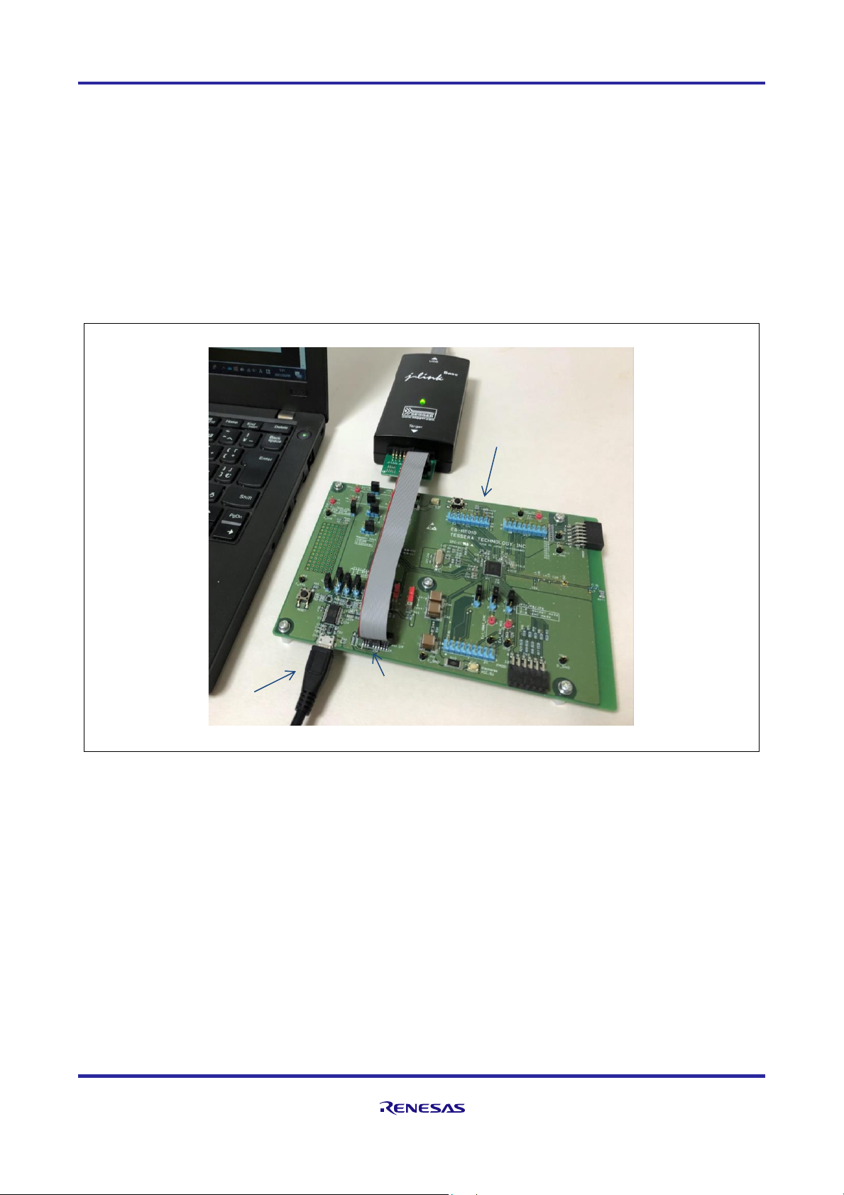
RE01B Group Getting Started Guide to Development Using CMSIS Package
R01AN5310EJ0100 Rev.1.00 Page 90 of 129
Mar. 15, 2021
6.3 User Program Creation Example
6.3.1 Example of Using a Peripheral Function Driver (USART Communication by SCI) (1) Application overview
This software performs serial communication (transmission only) using SCI. Since a serial-USB converter IC
(no programming required) is mounted on the evaluation board, the data sent from SCI is converted to USB
and displayed on terminal software on a PC.
Execute the sample code, and confirm that LED2 (orange) is turned on by the BoardInit function and the sent
character string is repeatedly displayed on the terminal screen of the PC.
(2) Sample code execution image
(3) Procedure up to execution
This application uses the "R_USART" peripheral function driver. In the main.c file, include the extension
header file provided by Renesas. Pin settings are required because the external pins TXD2 and RXD2 of SCI2
are used.
• Creating a main.c file (including necessary header files, main function, callback function, BoardInit
function executed at startup)
• [Preparation] Editing of pin.c file (P609 → TXD2, P608 → RXD2 settings)
• [Preparation] Editing of r_system_cfg.h file (setting of SCI2 transmission completion interrupt)
In this example, there is no need to edit r_usart_cfg.h. Note that the above settings are the minimum settings
required to execute this application. When applying this to other applications, refer to the driver specifications
and enter the necessary settings.
LED2 (orange) lights up
as a result of the BoardInit
function
Serial-USB converter IC
(no programming required)
USB cable for data communication
(Micro USB Type-B connector
on the evaluation board side)

RE01B Group Getting Started Guide to Development Using CMSIS Package
R01AN5310EJ0100 Rev.1.00 Page 91 of 129
Mar. 15, 2021
(4) Create sample code and edit related files ◼ main.c file (1/3)
(continued on next page)
/******************************************************************************************
* Main function: USART sample program
******************************************************************************************/
#include "RE01B_1500KB.h"
#include "r_core_cfg.h"
#include "r_system_api.h"
#include "r_lpm_api.h"
#include "R_Driver_USART.h"
extern ARM_DRIVER_USART Driver_USART2;
static ARM_DRIVER_USART *gsp_sci2_dev = &Driver_USART2;
static uint8_t send_data[]="Hello World! "; /* Transmit buffer */
static void usart_callback(uint32_t event);
bool send_comp_flag = true;
/*****************************************************************
* Main function
*****************************************************************/
int main()
{
uint32_t wait_count;
R_SYS_CodeCopy();
R_SYS_Initialize();
R_LPM_Initialize();
R_LPM_IOPowerSupplyModeSet(0x00);
/***********************************************
* USART(SCI2) settings
***********************************************/
/** Initialize USART and set callback function **/
gsp_sci2_dev->Initialize(usart_callback);
/** Initialize USART PowerControl **/
gsp_sci2_dev->PowerControl(ARM_POWER_FULL);
/** Initialize USART transmition settings **/
gsp_sci2_dev->Control((ARM_USART_MODE_ASYNCHRONOUS | /* Asynchronous mode */
ARM_USART_DATA_BITS_8 | /* 8 Data bits */
ARM_USART_PARITY_NONE | /* No Parity */
ARM_USART_STOP_BITS_2 | /* 2 Stop bit */
ARM_USART_FLOW_CONTROL_NONE) /* No Flow Control */
,9600);
gsp_sci2_dev->Control(ARM_USART_CONTROL_TX,1); /* Enable transmission */
Includes header file of common function driver
and R_USART driver (extended function)
Declaration to use instance of
R_USART driver channel 2
Initial settings
Registers the callback function created by the user
with the driver initialization function (when setting
by instance, it is not necessary to specify the USART
resource in the argument)
Releases the USART module stop
Communication
mode settings

RE01B Group Getting Started Guide to Development Using CMSIS Package
R01AN5310EJ0100 Rev.1.00 Page 92 of 129
Mar. 15, 2021
◼ main.c file (2/3)
(continued on next page)
/***********************************************
* USART transmission loop
***********************************************/
while(1)
{
if(true == send_comp_flag) /* Waiting for transmission completion */
{
send_comp_flag = false; /* Clear flag */
gsp_sci2_dev->Send(&send_data[0], sizeof(send_data));
for (wait_count=0 ; wait_count < 0x400000; wait_count++);
}
}
return 0;
} /*end of main */
/*****************************************************************
* Usart_callback function (USART event interrupt)
*****************************************************************/
static void usart_callback(uint32_t event)
{
switch( event ) /* Check event */
{
case ARM_USART_EVENT_SEND_COMPLETE:
{
send_comp_flag = true; /* Set flag */
}
break;
case ARM_USART_EVENT_RECEIVE_COMPLETE:
{
/* Describe processing when receiving is completed */
}
break;
default:
{
/* Resume reception when a reception error occurs */
}
break;
}
} /* End of usart_callback */
Clears the transmission completion flag
and transmit data
Sets the transmission complete flag
in the interrupt callback function
Transmission interval

RE01B Group Getting Started Guide to Development Using CMSIS Package
R01AN5310EJ0100 Rev.1.00 Page 93 of 129
Mar. 15, 2021
◼ main.c file (3/3)
◼ P506 and P500 ports of the evaluation board set by the BoardInit function
(* Refer to the evaluation board documentation for details.)
/******************************************************************************************
* BoardInit function for start-up
* PORT5 Settings: Set P506(LED2) and P500(Load Switch IC Control) to output
******************************************************************************************/
void BoardInit(void)
{
/* PODR: Port Output Data
b15-b10 (PODR15-00): Low */
PORT5->PODR = 0x0000;
/* PDR: Port Direction
b15-b07 (PDR15-07) : Input
b6 (PDR06) : Output
b5-b1 (PDR05-01) : Input
b0 (PDR00) : Output */
PORT5->PDR = 0x0041;
} /* End of BoardInit */
/* End of File */
P500
Load switch
IN OUT
GND
CONTROL
TCK107
P506
LED2 (orange)
Lights up when P506 Low output
IC4
At the start of operation, set the following as output ports (Low)
・ P506: LED (lights up orange)
・ P500: CONTROL terminal of load switch IC (output prohibited)

RE01B Group Getting Started Guide to Development Using CMSIS Package
R01AN5310EJ0100 Rev.1.00 Page 94 of 129
Mar. 15, 2021
◼ [Preparation] Editing of the pin.c File
Set TXD2 to P609 and RXD2 to P608. (TXD2 can also be set to P102 or P501, and RXD2 can be set to
P101 or P502, but put a "//" symbol at the beginning of those settings and comment out.)
◼ Circuit around TXD2 and RXD2 of evaluation board (outline)
(* Refer to the evaluation board documentation for details.)
/**************************************************************************//**
* @brief This function sets Pin of SCI2.
*******************************************************************************/
/* Function Name : R_SCI_Pinset_CH2 */
void R_SCI_Pinset_CH2(void)
{
/* Disable protection for PFS function (Set to PWPR register) */
R_SYS_RegisterProtectDisable(SYSTEM_REG_PROTECT_MPC);
/* TXD2 : P609 */
PFS->P609PFS_b.ASEL = 0U; /* 0: Do not use as an analog pin, 1: Use as an analog pin. */
PFS->P609PFS_b.ISEL = 0U; /* 0: Do not use as an IRQn input pin, 1: Use as an IRQn input pin. */
/* When using SCI in I2C mode, set the pin to NMOS Open drain. */
// PFS->P609PFS_b.NCODR = 1U; /* 0: CMOS output, 1: NMOS open-drain output. */
// PFS->P609PFS_b.PCODR = 0U; /* 0: CMOS output, 1: PMOS open-drain output. */
PFS->P609PFS_b.PSEL = R_PIN_PRV_SCI_PSEL_04;
PFS->P609PFS_b.PMR = 1U; /* 0: Use the pin as a general I/O port, 1: Use the pin as a peripheral module. */
/* RXD2 : P608 */
PFS->P608PFS_b.ASEL = 0U; /* 0: Do not use as an analog pin, 1: Use as an analog pin. */
PFS->P608PFS_b.ISEL = 0U; /* 0: Do not use as an IRQn input pin, 1: Use as an IRQn input pin. */
/* When using SCI in I2C mode, set the pin to NMOS Open drain. */
// PFS->P608PFS_b.NCODR = 1U; /* 0: CMOS output, 1: NMOS open-drain output. */
// PFS->P608PFS_b.PCODR = 0U; /* 0: CMOS output, 1: PMOS open-drain output. */
PFS->P608PFS_b.PSEL = R_PIN_PRV_SCI_PSEL_04;
PFS->P608PFS_b.PMR = 1U; /* 0: Use the pin as a general I/O port, 1: Use the pin as a peripheral module. */
R_SYS_RegisterProtectEnable(SYSTEM_REG_PROTECT_MPC);
}/* End of function R_SCI_Pinset_CH4() */
To USB
Port
P609/SCI_TXD2
P608/SCI_RXD2
Serial-USB
conversion IC
JP10
1
3
2
1
3
2
JP11
LED3 (red)
LED4 (yellow-green)
IC3
FT232RL
RXD
TXD
USBDM
USBDP
micro USB Type-B
connector
Set P609 to TXD2
Set P608 to RXD2

RE01B Group Getting Started Guide to Development Using CMSIS Package
R01AN5310EJ0100 Rev.1.00 Page 95 of 129
Mar. 15, 2021
◼ [Preparation] Editing of r_system_cfg.h File (Setting of SCI Transmission Completion Interrupt)
/**************************************************************************************************************//**
* @name IRQ_EVENT_LINK_NUMBER_CONFIG_PART_2
* Definition of IRQ event link number configuration part 2
* Please select one of the IRQ event numbers SYSTEM_IRQ_EVENT_NUMBER1/9/17/25 or
* SYSTEM_IRQ_EVENT_NUMBER5/13/21/29 for the following interrupt events.@n
* Do not duplicate the IRQ event link number.
* And, the Error Handlers had better be set smaller event link number
* than those peripheral Transmit and Receive Handlers.
*****************************************************************************************************************/
/* @{ */
// Omitted
#define SYSTEM_CFG_EVENT_NUMBER_GPT1_UDF (SYSTEM_IRQ_EVENT_NUMBER_NOT_USED) /*!< Numbers 5/13/21/29 only */
#define SYSTEM_CFG_EVENT_NUMBER_GPT3_CCMPB (SYSTEM_IRQ_EVENT_NUMBER_NOT_USED) /*!< Numbers 5/13/21/29 only */
#define SYSTEM_CFG_EVENT_NUMBER_GPT5_CCMPB (SYSTEM_IRQ_EVENT_NUMBER_NOT_USED) /*!< Numbers 5/13/21/29 only */
#define SYSTEM_CFG_EVENT_NUMBER_SCI1_AM (SYSTEM_IRQ_EVENT_NUMBER_NOT_USED) /*!< Numbers 5/13/21/29 only */
#define SYSTEM_CFG_EVENT_NUMBER_SCI2_TXI (SYSTEM_IRQ_EVENT_NUMBER5) /*!< Numbers 5/13/21/29 only */
#define SYSTEM_CFG_EVENT_NUMBER_SCI4_TXI (SYSTEM_IRQ_EVENT_NUMBER_NOT_USED) /*!< Numbers 5/13/21/29 only */
#define SYSTEM_CFG_EVENT_NUMBER_SCI9_TXI (SYSTEM_IRQ_EVENT_NUMBER_NOT_USED) /*!< Numbers 5/13/21/29 only */
#define SYSTEM_CFG_EVENT_NUMBER_SPI1_SPTI (SYSTEM_IRQ_EVENT_NUMBER_NOT_USED) /*!< Numbers 5/13/21/29 only */ /* @} */
// Omitted
Assign SCI2_TXI
to IRQ5

RE01B Group Getting Started Guide to Development Using CMSIS Package
R01AN5310EJ0100 Rev.1.00 Page 96 of 129
Mar. 15, 2021
6.3.2 Example When Peripheral Function Driver is not Used (AGT Asynchronous General-purpose
Timer Application)
(1) Overview of sample code
This sample code blinks LED2 by timer interrupt using AGT1. When the peripheral function driver is not used,
the division ratio of the peripheral clock (PCLKB) can be set by the R_CORE driver, but the clock division ratio
in the AGT must be set by directly operating the AGT register. Interrupts are set using the function of the
R_SYSTEM driver.
In this sample code, the output pin of the AGT timer is not used, and when a timer interrupt occurs, the LED
is blinked by the port control, so editing pin.c is unnecessary. Execute the sample code and confirm that LED2
(orange) blinks at the interval set in the AGT timer.
(2) Sample code execution image
(3) Procedure up to execution
By including the register definition file "RE01B_1500KB.h" in the main.c file, hardware registers can be
accessed by register name instead of address. LED2 is controlled by the port, so no pin setting is required.
• Creating a main.c file (including necessary header files, main function, callback function, BoardInit
function executed at startup)
• [Preparation] Editing of r_system_cfg.h file (setting of AGT1 timer interrupt)
• [Preparation] Editing of r_core_cfg.h file (setting of division ratio of peripheral clock PCLKB)
Note that the above settings are the minimum settings required to execute this application. When applying
to other applications, refer to the driver specifications and make the necessary settings.
LED2 blinks at set time
intervals

RE01B Group Getting Started Guide to Development Using CMSIS Package
R01AN5310EJ0100 Rev.1.00 Page 97 of 129
Mar. 15, 2021
(4) Create sample code and edit related files ◼ main.c File (1/2)
(continued on next page)
/******************************************************************************************
* Main function: AGT sample program
******************************************************************************************/
#include "RE01B_1500KB.h"
#include "r_core_cfg.h"
#include "r_system_api.h"
#include "r_lpm_api.h"
#include "pin.h"
static void agt_callback(void);
/* main function */
int main (void)
{
R_SYS_CodeCopy();
R_SYS_Initialize();
R_LPM_Initialize();
R_LPM_IOPowerSupplyModeSet(LPM_IOPOWER_SUPPLY_NONE);
/***********************************************
* AGT1 settings
***********************************************/
R_LPM_ModuleStart( LPM_MSTP_AGT1 );
R_SYS_ResourceLock( SYSTEM_LOCK_AGT1 );
AGT1->AGTMR1_b.TCK = 1; /* Count source = PCLKB(500kHz)/8 = 62.5kHz */
AGT1->AGTMR1_b.TMOD = 0; /* Timer mode *
AGT1->AGTMR2_b.LPM = 0; /* Low power - normal mode */
AGT1->AGT = 0x7A12; /* 0.5s = 16us x 31250(0x7A12) */
/***********************************************
* AGT1 Interrupt settings
***********************************************/
R_SYS_IrqStatusClear(SYSTEM_CFG_EVENT_NUMBER_AGT1_AGTI);
R_NVIC_ClearPendingIRQ(SYSTEM_CFG_EVENT_NUMBER_AGT1_AGTI);
R_NVIC_SetPriority(SYSTEM_CFG_EVENT_NUMBER_AGT1_AGTI,0);
R_NVIC_EnableIRQ(SYSTEM_CFG_EVENT_NUMBER_AGT1_AGTI);
R_SYS_IrqEventLinkSet(SYSTEM_CFG_EVENT_NUMBER_AGT1_AGTI, 0x06, agt_callback);
/***********************************************
* AGT1 Start (main loop)
***********************************************/
PORT5->PODR = 0x0040; /* LED2 off */
AGT1->AGTCR_b.TSTART=1; /* AGT1 Counter Start */
while (1) ; /* main loop */
return 0;
} /* End of main */
Include required header files
(Include RE01B_1500KB.h to operate
by register name)
Initial setting
Cancel AGT1 module stop functionAGT1,
Hardware resource lock
Write directly to AGT
registers using register
definition file
Set interrupt for AGT1_AGTI
using R_SYS driver
Sets up event links and registers
user-created callback functions

RE01B Group Getting Started Guide to Development Using CMSIS Package
R01AN5310EJ0100 Rev.1.00 Page 98 of 129
Mar. 15, 2021
◼ main.c File (1/2)
◼ [Preparation] Editing of r_system_cfg.h File (Timer Interrupt)
/*****************************************************************
* agt_callback function (AGT1 timer interrupt)
*****************************************************************/
static void agt_callback (void)
{
AGT1->AGTCR_b.TUNDF = 0; /* AGT1 Underflow clear */
PORT5->PODR ^= 0x0040; /* LED2 blinking */
AGT1->AGTCR_b.TSTART = 1; /* AGT1 Counter Re-start */
return;
} /* End of function agt_callback */
// Omitted below: For the BoardInit function, refer to the USART application example
/**********************************************************************//**
* @name IRQ_EVENT_LINK_NUMBER_CONFIG_PART_1
* Definition of IRQ event link number configuration part 1
* Please select one of the IRQ event numbers SYSTEM_IRQ_EVENT_NUMBER0/8/16/24 or
* SYSTEM_IRQ_EVENT_NUMBER4/12/20/28 for the following interrupt events.@n
* Do not duplicate the IRQ event link number.
* And, the Error Handlers had better be set smaller event link number
* than those peripheral Transmit and Receive Handlers.
**********************************************************************/
/* @{ */
#define SYSTEM_CFG_EVENT_NUMBER_PORT_IRQ0 (SYSTEM_IRQ_EVENT_NUMBER_NOT_USED)
#define SYSTEM_CFG_EVENT_NUMBER_DMAC0_INT (SYSTEM_IRQ_EVENT_NUMBER_NOT_USED)
#define SYSTEM_CFG_EVENT_NUMBER_DTC_COMPLETE (SYSTEM_IRQ_EVENT_NUMBER_NOT_USED)
#define SYSTEM_CFG_EVENT_NUMBER_ICU_SNZCANCEL (SYSTEM_IRQ_EVENT_NUMBER_NOT_USED)
#define SYSTEM_CFG_EVENT_NUMBER_LVD_LVD1 (SYSTEM_IRQ_EVENT_NUMBER_NOT_USED)
#define SYSTEM_CFG_EVENT_NUMBER_AGT1_AGTI (SYSTEM_IRQ_EVENT_NUMBER0)
#define SYSTEM_CFG_EVENT_NUMBER_WDT_NMIUNDF (SYSTEM_IRQ_EVENT_NUMBER_NOT_USED)
#define SYSTEM_CFG_EVENT_NUMBER_ADC140_ADI (SYSTEM_IRQ_EVENT_NUMBER_NOT_USED)
#define SYSTEM_CFG_EVENT_NUMBER_ADC140_WCMPM (SYSTEM_IRQ_EVENT_NUMBER_NOT_USED)
// Omitted
/* @} */
User-created callback function
(Clear underflow, invert LED output,
restart timer)
Assigns AGT1_AGTI
to IRQ0

RE01B Group Getting Started Guide to Development Using CMSIS Package
R01AN5310EJ0100 Rev.1.00 Page 99 of 129
Mar. 15, 2021
◼ [Preparation] Editing of r_core_cfg.h File (Setting of PCLKB Division Ratio)
◼ AGT Clock Setting Overview
(* For details, refer to the target device User's Manual: Hardware.)
// Excerpt
/**********************************************************************************************//**
* @brief PCLKB frequency division ratio select(SCKDIVCR.PCKB)@n
* The following frequency relationship is required between ICLK/PCLKA and PCLKB@n
* ICLK/PCLKA:PCLKB = N:1 (N : integer number)@n
* 0 = /1 (default)@n
* 1 = /2@n
* 2 = /4@n
* 3 = /8@n
* 4 = /16@n
* 5 = /32@n
* 6 = /64@n
*************************************************************************************************/
#define SYSTEM_CFG_PCKB_DIV (6)
AGTMR1 register
TCK[2:0]
AGT register
AGTLCLK
AGTSCLK
16bit counter
AGTMR2 register
CKS[2:0]
Divider
000
001
011
100
101
110
AGT0
Underflow
PCLKB
PCLKB/8
PCLKB/2
Prescaler
1,2,4,8,~
128
1/1
1/2
1/4
1/64
:
:
PCKB[2:0]
Peripheral
module clock B
PCLKB
Asynchronous general-
purpose timer (AGT)
Clock generation
circuit
CKSEL[2:0]
:
:
:
main clock
sub clock
HOCO
MOCO
LOCO
R_SYS driver makes settings
based on the contents of
r_core_cfg.h
The user makes settings
by directly operating the
peripheral function registers
Oscillation
source selector
Division
ratio selector
Count
source selector
Settings for using PCLKB (divided by 64)
as the AGT clock source

RE01B Group Getting Started Guide to Development Using CMSIS Package
R01AN5310EJ0100 Rev.1.00 Page 100 of 129
Mar. 15, 2021
7. Creating a Project
This chapter describes the method for changing settings according to the operating environment after starting
the project included with this package.
7.1 EWARM Version
Double-click the executable file included in this package and start the project on EWARM.
Figure 7-1 Project Executable File (EWARM)
The project settings are set on the project option screen. See Figure 7-2 to display the option screen.
Figure 7-2 Displaying Option Screen (EWARM)
├
config
│
└
RE01B_1500KB.icf
├
Flash Debug
├
project.dep
├
project.ewd
├
project.ewp
├
project.ewt
├
project.eww
└
RE01B_1500KB_DFP HardwareDebug.launch
Linker file
For EWARM
(IAR compiler)
Executable file (double-click to launch EWARM)
Select “Project” → ”Options”
 Loading...