

Page 1
Application Note
Renesas RA Family
RA AWS MQTT/TLS Cloud Connectivity Solution
Introduction
This application note describes IoT Cloud connectivity solution in general, provides a brief introduction to IoT
Cloud providers like Amazon Web Services (AWS), and covers the FSP MQTT/TLS module and its features.
The application example provided in the package uses AWS IoT Core. The detailed steps in this document
show first-time AWS IoT Core users how to configure the AWS IoT Core platform to run this application
example.
This application note enables developers to effectively use the FSP MQTT/TLS modules in end-product
design. Upon completion of this guide, developers will be able to add the “AWS MQTT Client”, “Mbed TLS”,
“Secure sockets on WiFi” using Silex Wi-Fi modules; and “secure sockets on FreeRTOS plus TCP” using
Ethernet interface, configure them correctly for the target application, and write code using the included
application example code as a reference for efficient starting point.
References to detailed API descriptions, and other application projects that demonstrate more advanced
uses of the module, are in the FSP User’s Manual (available at: https://renesas.github.io/fsp/
as a valuable resource in creating more complex designs.
This MQTT/TLS AWS Cloud Connectivity solution is supported on the EK-RA6M3 (Both Ethernet and Wi-Fi )
and EK-RA6M4 (Wi-Fi support only) kits.
), which serves
Applies to:
• RA6M4 MCU Group
• RA6M3 MCU Group
• RA6M2 MCU Group
• RA6M1 MCU Group
Required Resources
To build and run the MQTT/TLS application example, the following resources are needed.
Development tools and software
2
• e
studio ISDE v20.10.0 or later (renesas.com/us/en/software-tool/e-studio)
• Flexible Software Package ( FSP) 2.2.0 or later (renesas.com/us/en/software-tool/flexible-software-
package-fsp)
• SEGGER J-Link® USB driver (renesas.com/synergy/jlinksynergy).
• SEGGER RTT Viewer V 6.95a (https://www.segger.com/products/debug-probes/j-link/tools/rtt-viewer/)
• SEGGER SWO Viewer (https://www.segger.com/products/debug-probes/j-link/tools/j-link-swo-viewer/)
Hardware
• Renesas RA™ EK-RA6M3 kit (renesas.com/ra/ek-ra6m3
• Renesas RA™ EK-RA6M4 kit (renesas.com/ra/ek-ra6m4).
• Renesas Silex PmodTM based Wi-Fi Module (renesas.com/wi-fi-pmod).
Note: The Silex PmodTM module is not included in the EK-RA6M3 or EK-RA6M4 kit and must be
ordered separately.
®
• PC running Windows
Edge, Mozilla Firefox, or Safari).
• Micro USB cables (included as part of the kit)
10; and an installed web browser (Google Chrome, Internet Explorer, Microsoft
).
R11AN0453EU0105 Rev.1.05 Page 1 of 1
Feb.11.21
Page 2

Renesas RA Family RA AWS MQTT/TLS Cloud Connectivity Solution
Prerequisites and Intended Audience
This application note assumes that the user is adept in operating the Renesas e2 studio ISDE with Flexible
Software Package (FSP). If not, we recommend they read and follow procedures in the FSP User Manual
sections for ‘Starting Development’ including ‘Debug the Blinky Project’. Doing so enables familiarization with
2
studio and FSP and validates proper debug connection to the target board. In addition, this application
e
note assumes prior knowledge of MQTT/TLS and its communication protocols.
The intended audience is users who want to develop applications with MQTT/TLS modules using Renesas
™
RA6 MCU Series.
RA
2
Note: If you are a first time user of e
on your system in order to run the Blinky Project and to get familiar with the e
studio and FSP, we highly recommend you install e2 studio and FSP
2
studio and FSP
development environment before proceeding to the next sections.
Prerequisites
1. Access to online documentation available in the Cloud Connectivity References section.
2. Access to latest documentation for identified Renesas Flexible Software Package.
3. Prior knowledge of operating e
2
studio and built-in (or standalone) RA Configurator.
4. Access to associated hardware documentation such as User Manu als , Schematics, and so forth.
Using this Application Note
Section 1 of this document covers the General Overview of the Cloud Connectivity, AWS IOT Core, MQTT
and TLS Protocols and Device certificates and Keys used in the Cloud Connectivity.
Sections 2 to 5 cover the usage of FSP configurator to add the MQTT Client, Secure Sockets, Integrated
TLS client and MQTT components to the project.
Section 6.1 and 6.2 co ver Clou d con nec tivi t y Applic ati on Project architecture, its sof tware components
overview.
Section 6.3 covers the step by step procedure to recreate the bundled Application Project using the FSP
Configurator.
Note: For a quick validation using the provided application project, you can skip the above sections a nd go
to section 6.5 for instructions on importing, building and running the Application project on the EK
board. Users are still required to provide necessary user credentials for the application as described
in sections 6.4, 6.5, and 6.6 before validatio n can be d one using the steps described in the section
6.7.
Section 6.4 covers the Cloud side configuration required to run the Application Project.
Section 6.5 covers the importing, building, and running the Application Project on the EK board.
Section 6.6 covers the User specific credentials to run the application.
Section 6.7 covers the validation of the Application Project from Board and from the Cloud.
R11AN0453EU0105 Rev.1.05 Page 2 of 2
Feb.11.21
Page 3

Renesas RA Family RA AWS MQTT/TLS Cloud Connectivity Solution
Contents
1. Introduction to Components for Cloud Connectivity ................................................................. 4
1.1 General Overview .................................................................................................................................... 4
1.2 Cloud Service Provider ............................................................................................................................ 4
1.3 AWS IoT Core ......................................................................................................................................... 5
1.4 MQTT Protocol Overview ........................................................................................................................ 5
1.5 TLS Protocol Overview ............................................................................................................................ 5
1.6 Device Certificates, CA, and Keys .......................................................................................................... 6
2. AWS MQTT Client with RA FSP .............................................................................................. 6
3. Secure Sockets Implementation .............................................................................................. 8
4. Mbed TLS ................................................................................................................................ 9
5. MQTT Module APIs Usage .................................................................................................... 10
6. Cloud Connectivity Application Example ................................................................................ 10
6.1 Overview ................................................................................................................................................ 10
6.2 MQTT/TLS Application SW Architecture Overview ............................................................................... 12
6.3 Creating the Application Project using the FSP Configurator ............................................................... 13
6.4 MQTT/TLS Configuration ...................................................................................................................... 21
6.4.1 IoT Cloud Configuration (AWS) ........................................................................................................... 25
6.4.2 Creating a Device on AWS IoT Core................................................................................................... 26
6.4.3 Generating Device Certificate and Keys ............................................................................................. 32
6.4.4 Creating a Policy for a Device ............................................................................................................. 36
6.4.5 Connecting the Certificate to the Policy .............................................................................................. 38
6.5 Running the MQTT/TLS Application Example ...................................................................................... 40
6.5.1 Importing, Building and Loading the Project ....................................................................................... 40
6.5.2 Loading the Executable Binary into the Target MCU .......................................................................... 41
6.5.3 Powering up the Board ........................................................................................................................ 41
6.6 Connecting to AWS IoT ......................................................................................................................... 42
6.6.1 Wi-Fi Credentials ................................................................................................................................. 42
6.6.2 AWS IoT Credentials ........................................................................................................................... 42
6.7 Verifying the Application Pr oj ect ............................................................................................................ 43
7. MQTT/TLS Module Next Steps .............................................................................................. 45
8. Cloud Connectivity References .............................................................................................. 45
9. Known Issues ........................................................................................................................ 46
Revision History ............................................................................................................................ 48
R11AN0453EU0105 Rev.1.05 Page 3 of 3
Feb.11.21
Page 4
Renesas RA Family RA AWS MQTT/TLS Cloud Connectivity Solution
1. Introduction to Components for Cloud Connectivity
1.1 General Overview
The Internet-of-Things (IoT) is a global infrastructure for the information society, enabling advanced services
by interconnecting (physical and virtual) things based on existing and evolving int e roper ab le inf ormation and
communication technologies. The ‘things’ in this definition are objects in the physical world (physical objects)
or information world (virtual) that can be identified and integrated into communication networks. In the
context of the IoT, a ‘device’ is a piece of equipment with the mandatory capabilities of communication and
the optional capabilities of sensing, actuation, data capture, data storage and data processing [1].
Communication is often performed with providers of network-hosted services, infrastructure, and business
applications to process/analyze the generated data and manage the devices. Such providers are called
Cloud Service Providers. While there are many manufacturers for devices and cloud service providers, for
the context of this application note, the device is a Renesas RA Microcontroller (MCU) connecting to services
provided by Amazon Web Services (AWS) for IoT.
1.2 Cloud Se r vice P r ovider
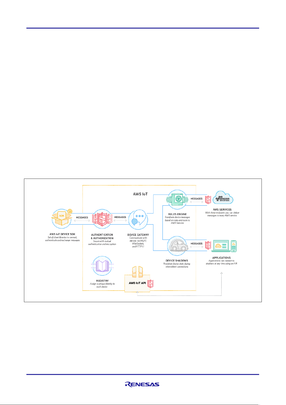
AWS IoT is a platform that enables users to connect devices to AWS Services and other devices, secure
data and interactions, process and act upon device data, and enable applications to interact with devices
even when they are offline. As a Cloud Service Provider, AWS IoT provides the ability to:
• Connect and manage devices.
• Secure device connections and data .
• Process and act upon device data.
• Read and set device state at any time.
The following Figure 1 summarizes the features provided by AWS IoT [2]
Figure 1. AWS IoT Features, Service Components, and Data Flow Diagram
A key feature provided by AWS is the AWS IoT Software Development Kit (SDK) written in C to allow
devices such as sensors, actuators, embedded micro-controllers, or smart appliances; to connect,
authenticate, and exchange messages with AWS IoT using the MQTT, HTTP, or WebSocket’s protocols.
This application note focuses on configuring and using the AWS IoT Device SDK and the included MQTT
protocol available through the Renesas Flexible Software Package (FSP) for Renesas RA MCUs.
R11AN0453EU0105 Rev.1.05 Page 4 of 4
Feb.11.21
Page 5
Renesas RA Family RA AWS MQTT/TLS Cloud Connectivity Solution
Secure Crypto Hardw are A c c elerati on
Supported
Key Format Supported
AES, ECC, RSA
Hash
SHA-256
Cipher
AES
Public Key Cryptography
ECC, ECDSA, RSA
Message Authentication Code (MAC)
HKDF
1.3 AWS IoT Core
AWS IoT Core is a managed cloud service that lets connected devices easily and securely interact with
cloud applications and other devices. AWS IoT Core can support billions of devices and trillions of
messages. It can process and route messages to AWS endpoints and to other devices reliably and securely.
With AWS IoT Core, customer applications can keep track of all devices, all the time, even when they are
not connected [3].
AWS IoT Core addresses security concerns for the infrastructure by implementing mutual authentication and
encryption. AWS IoT Core provides automated configuration and authentication upon a device’s first
connection to AWS IoT Core, as well as end-to-end encryption throughout all points of connection, so that
data is never exchanged between devices and AWS IoT Core without proven identity [3].
This application note focuses on complementing the security needs of AWS IoT Core through installing a
proven identity for the RA MCU by storing a X.509 certificate and asymmetric cryptography keys in Privacy
Enhanced Mail (PEM) format in the on-board flash. The RA MCU has on-chip security features, such as Key
Wrapping, to protect the private key associated with the public key and the certificate associated with the
1
device
Cryptography Engine (SCE) and API available through the FSP. The SCE is used to accelerate symmetric
encryption/decryption of data between the connected device and AWS IoT, allowing the ARM Cortex-M
processor to perform other application specific computations.
. Additionally, RA MCUs can also generate asymmetric keys using features of the Secure
1.4 MQTT Protoc ol Overview
Message Queuing Telemetry Transport (MQTT) is featured in this application note as it is a lightwe ig h t
communication protocol specifically designed to tolerate intermittent connections, minimize the code footprint
on devices, and reduce network bandwidth requirements. MQTT uses a publish/subscribe architecture which
is designed to be open and easy to implement, with up to thousands of remote clients capable of being
supported by a single server. These characteristics make MQTT ideal for use in constrained environments
where network bandwidth is low or where there is high latency and with remote devices that might have
limited processing capabilities and memory [4]. The RA MCU device in this application note implements a
MQTT Client which communicates with AWS IoT and exchanges example telemetry information, such as
MCU temperature, and MCU GPIO status.
1.5 TLS Pr otoc ol Overview
The primary goal of the Transport Layer Security (TLS) protocol is to provide privacy and data integrity
between two communicating applications [5] or endpoints. AWS IoT mandates use of secure
communication. Consequentially, all traffic to and from AWS IoT is sent securely using TLS [6]. TLS protocol
version 1.2 or later is used to ensure the confidentiality of the application protocols supported by AWS IoT. A
variety of TLS Cipher Suites are supported [7] . This application note configures the RA Flexible Software
Package for the MCU based device to provide the following capabilities and AWS IoT negotiates the
appropriate TLS Cipher Suite configuration to maximize security.
Table 1. TLS Capabilities in RA FSP
On top of these above supported features, Mbed Crypto middleware also supports a variety of features
which can be enabled through the RA Configurator. Refer to the FSP UM section for the Crypto Middleware
(rm_psa_crypto).
1
This application note does not focus on using Key Wrapping for securely storing the private key for devices
deployed in a production environment.
R11AN0453EU0105 Rev.1.05 Page 5 of 5
Feb.11.21
Page 6
Renesas RA Family RA AWS MQTT/TLS Cloud Connectivity Solution
1.6 Device Certificates, CA, and Keys
Device certificates, Certificate Authorities, and Asymmetric Key Pairs create the foundation for trust needed
for a secure environment. The background information on these commonly used components in AWS is as
follows:
A digital certificate is a document in a known format that provides information about the identity of a device.
X.509 is a standard that includes the format definition for public-key certificate, attribute certificate, certificate
revocation list (CRL) and attribute certificate revocation list (ACRL) [8]. X.509 defined certificate formats
(X.509 Certificate) are commonly used on the internet and in AWS IoT for authenticating a remote
entity/endpoint, that is, a Client and/or Server . In this appl ic ati on note , an X.509 certificate and asymmetric
cryptography key pair (public and private keys) are generated from AWS IoT and installed (during binary
compilation) into the RA MCU device running the MQTT Client to establish a known identity. In addition, a
root Certification Authority (CA) certificate is also downloaded and used by the device to authenticate the
connection to the AWS IoT gateway.
Certification authority (CA) certificates are certificates that are issued by a CA to itself or to a second CA for
2
the purpose of creating a defined relationship between the two CAs
. The root CA certificate allows devices
to verify that they're communicating with AWS IoT Core and not another server impersonating AWS IoT
Core.
The public and private keys downloaded from AWS IoT use RSA algorithms for encryption, decryption,
3
signing and verification
. These key pairs, and certificates are used together in the TLS process to:
1. Verify device identity.
2. Exchange symmetric keys, for algorithms such as AES, for encrypting and decrypting data transfers
between endpoints.
2. AWS MQTT Client with RA FSP
The AWS MQTT library included in RA FSP can connect to either AWS MQTT or to any third party MQTT
broker such as Mosquitto [9]. The complete documentation for the library can be found on the AWS IoT
Device SDK C: MQTT website [10]. Primary features supported by the library are:
• MQTT connections over TLS to an AWS IoT Endpoint or Mosquitto server or any MQTT broker.
• Non-secure MQTT connections to Mosquitto servers.4
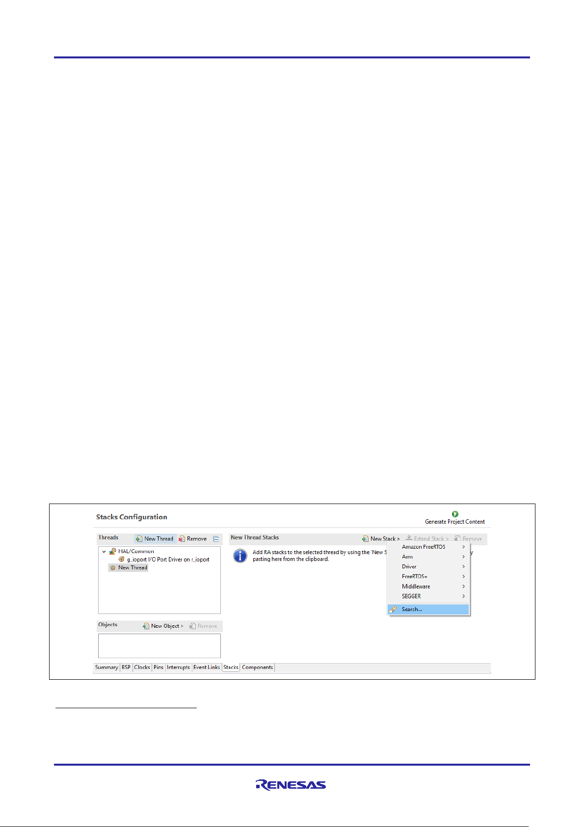
The AWS MQTT Client can be directly imported into a Thread Stack and is configured through the RA
Configuration Perspective. To add the AWS MQTT Client to a new thread, open the Configuration.xml with
the RA Configuration. While ensuring that the correct thread is selected on the left, use the tab for Stacks >
New Stack > Search and search for the keyword AWS MQTT Client.
Figure 2. AWS MQTT Client Module Selection
2
The root CA certificate provided by AWS IoT is signed by Digital Guardian.
3
Public Key length used is 2048 bits.
4
Recommended for local server testing and not for production/deployment.
R11AN0453EU0105 Rev.1.05 Page 6 of 6
Feb.11.21
Page 7
Renesas RA Family RA AWS MQTT/TLS Cloud Connectivity Solution
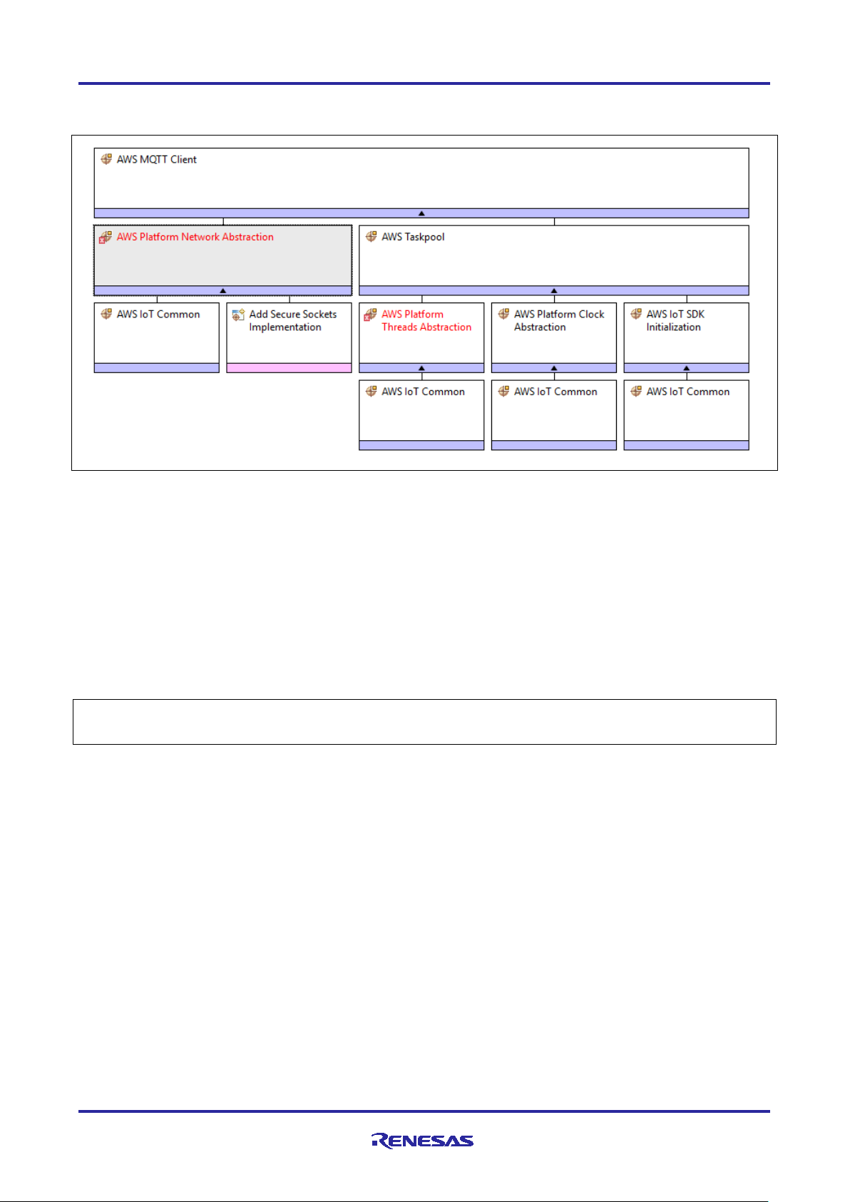
Adding the AWS MQTT Client Stack results in the default configuration with some unmet dependencies, as
shown below.
Figure 3. AWS MQTT Client Stack View
While the AWS MQTT Client stack shown contains a lot of dependencies and configurable properties, most
default settings can be used as-is. The following changes are needed to meet all unmet dependencies
(marked in red) for the AWS MQTT Client stack added to a new project (as shown above):
1. Enable Mutex and Recursive Mutex usage support as needed by IoT SDK and FreeRTOS in the created
Thread properties.
2. Optionally, adjust the AWS IoT Common properties for ‘IoT Thread Stack Size’ and ‘IoT Network Receive
Task Stack Size’.
Upon completion of the two steps above, the AWS MQTT Client is ready to accept a Secure Socket
Implementation, which has dependencies on using a TLS Session and an underlying TCP/IP
implementation.
Additional documentation on the AWS MQTT Client is available in the FSP User’s Manual under RA Flexible
Software Package Documentation > API Reference > Modules > AWS MQTT.
R11AN0453EU0105 Rev.1.05 Page 7 of 7
Feb.11.21
Page 8
Renesas RA Family RA AWS MQTT/TLS Cloud Connectivity Solution
3. Secure Sockets Implementation
The AWS Secure Sockets module provides an API that is based on the widely used BSD Sockets. While the
RA FSP contains a Secure Socket Implementation for both Wi-Fi and Ethernet, this application and app note
focuses on the use of an external Silex SX-ULPGN Pmod Wi-Fi module and on-board Ethernet.
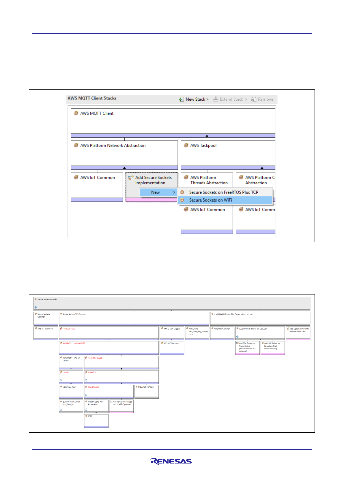
Secure Sockets can be added to the Thread Stack by clicking on Add Secure Sockets Implementation >
New > Secure Sockets on WiFi or Secure Sockets on FreeRTOS Plus TCP (for Ethernet).
Figure 4. Adding Secure Socket to the MQTT Client Module
Upon addition, the needed stack is complete and has unmet dependencies for the dependent modules. In
this case, the flash file system for the persistent storage is needed. This can be added by clicking on Add
AWS PKCS11 PAL > New > AWS PKCS11 PAL on LittleFS.
The added stack has unmet configuration for the sub-components, highlighted in red in the next Figure 5 that
should be addressed.
Figure 5. Expanded Secure Socket Module
R11AN0453EU0105 Rev.1.05 Page 8 of 8
Feb.11.21
Page 9
Renesas RA Family RA AWS MQTT/TLS Cloud Connectivity Solution
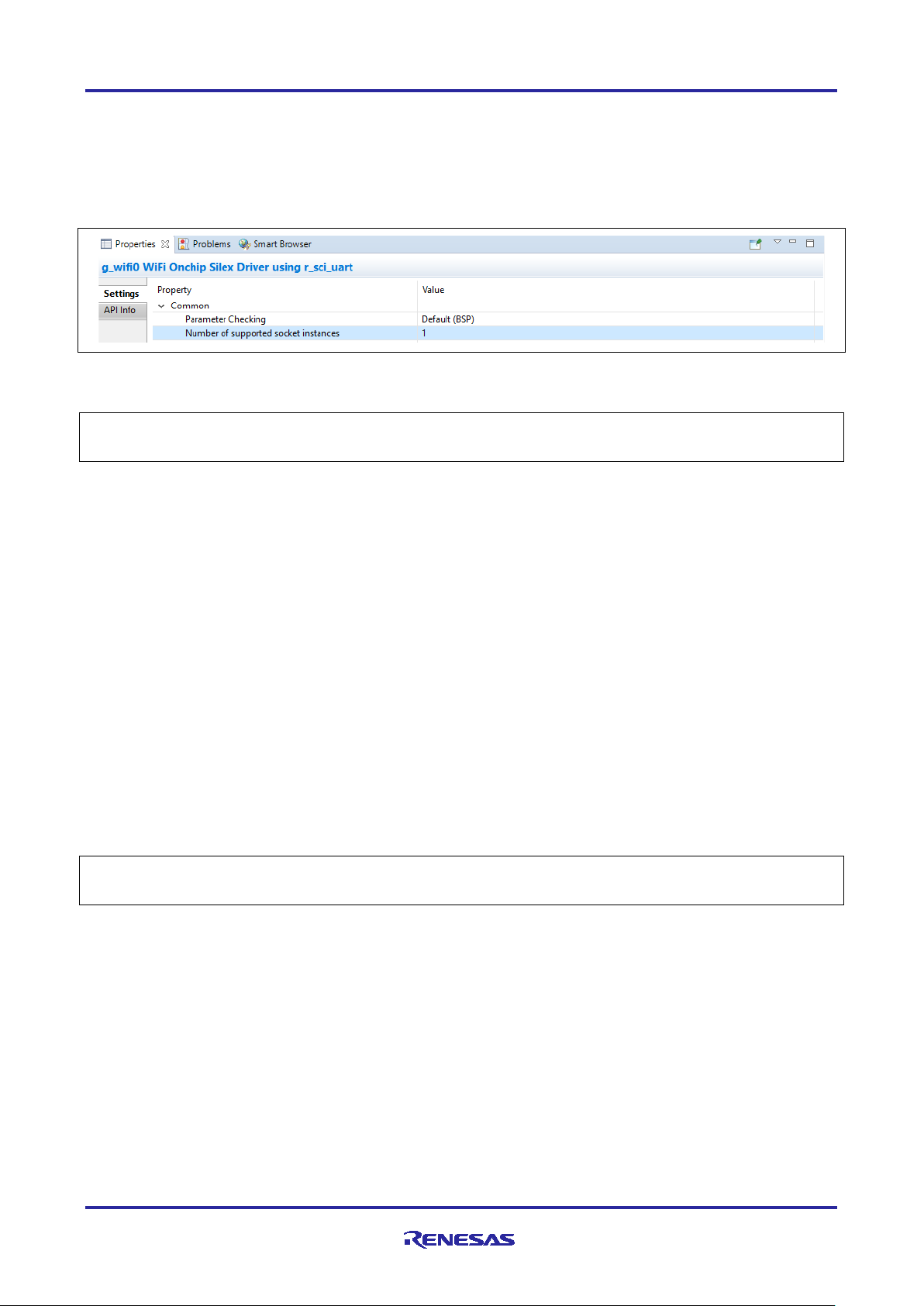
Satisfying most unmet dependencies as identified by the RA Configurator is recommended, however, some
are optional. For example, in the Wi-Fi application project, it uses one socket/UART for communication with
the Silex Wi-Fi Pmod. As a result, the property for Number of supported sockets instances should be set
to 1. This property is found by under Common Properties for Wi-Fi on-chip Silex Driver.
Note: To support multiple socket instances on this Wi-Fi module, a second UART on the Module needs to
be enabled. For the purpose of this Application Note, one socket is enough.
Figure 6. Socket Instances Selection
Remaining unmet dependencies which need to be addressed are related to the TLS stack discussed next.
Additional documentation on the AWS MQTT Client is available in the FSP User’s Manual under RA Flexible
Software Package Documentation > API Reference > Modules > AWS Secure Sockets.
4. Mbed TLS
mbed TLS is ARM's implementation of the TLS protocols as well as the cryptographic primitives required by
those implementations. mbed TLS is also solely used for its cryptographic features even if the TLS/SSL
portions are not used.
Secure Socket TLS Support uses FreeRTOS+TLS which eventually uses mbed TLS. Use of mbed TLS
requires configuration and operation of Mbed Crypto module which in turn operates the SCE on the MCU.
The following underlying mandatory changes are needed to a project using the Secure Sockets on
FreeRTOS+TLS module:
1. Use FreeRTOS heap implementation scheme 4 (first fit algorithm with coalescence algorithm) or scheme
5 (first fit algorithm with coalescence algorithm with heap spanning over multiple non adjacent/noncontiguous memory regions) [11].
2. Enable support for dynamic memory allocation in FreeRTOS.
3. Enable mbed TLS platform memory allocation layer.
4. Enable the mbed TLS generic threading Layer that handles default locks and mutexes for the user and
abstracts the threading layer to use an alternate thread-library.
5. Enable Elliptic Curve Diffie Helleman library.
6. Change FreeRTOS Total Heap Size to a value greater than 0x1500.
Additional documentation on the AWS MQTT Client is available in the FSP User’s Manual under RA Flexible
Software Package Documentation > API Reference > Modules > Crypto Middleware (rm_psa_crypto).
R11AN0453EU0105 Rev.1.05 Page 9 of 9
Feb.11.21
Page 10
Renesas RA Family RA AWS MQTT/TLS Cloud Connectivity Solution
API
Description
IotMqtt_Connect
Establish a new MQTT connection.
IotMqtt_Init
One-time initialization function for the MQTT library.
IotMqtt_IsSubscribed
Check if an MQTT connection has a subscription for a topic
filter.
IotMqtt_OperationType
Returns a string that describes an IotMqttOperationType_t.
IotMqtt_Publish
Publishes a message to the given topic name and receive an
asynchronous notification when the publish completes
IotMqtt_ReceiveCallback
Network receive callback for the MQTT library.
IotMqtt_strerror
Returns a string that describes an IotMqttError_t.
IotMqtt_Subscribe
Subscribes to the given array of topic filters and receive an
asynchronous notification when the subscribe completes.
IotMqtt_TimedSubscribe
Subscribes to the given array of topic filters with a timeout.
IotMqtt_TimedUnsubscribe
Unsubscribes from a given array of topic filters with a timeout.
IotMqtt_Unsubscribe
Unsubscribes from the given array of topic filters and receive
an asynchronous notification when the unsubscribe completes.
IotMqtt_Wait
Waits for an operation to complete.
IotMqtt_Disconnect
Closes an MQTT connection
5. MQTT Module APIs Usage
The AWS MQTT Client is documented online [12]. The following table lists APIs provided by AWS MQTT
Client that are used as a part of the Application Example.
Table 2. MQT T Module APIs
6. Cloud Connectivity Application Example
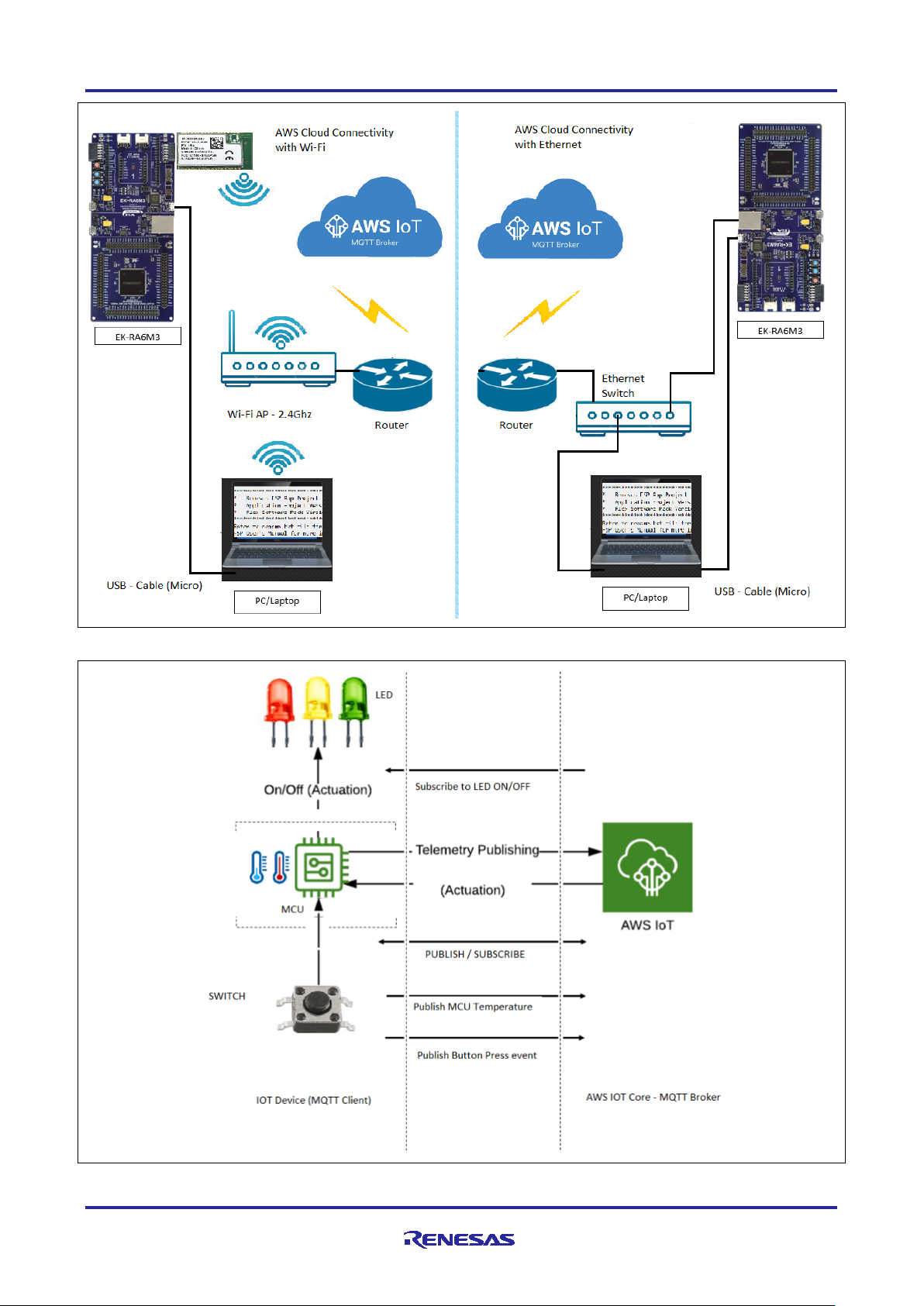
6.1 Overview
This application project demonstrates the usage of APIs available through the Renesas FSP-integrated
modules for Amazon IoT SDK C, mbed TLS module, Amazon FreeRTOS and HAL Drivers operating on
Renesas RA MCUs. Network connectivity is established using Ethernet or the Silex Pmod Wi-Fi Module. The
application running on a Renesas Evaluation Kit also serves as a reference system for the operation of
MQTT Client, mbed TLS/Crypto, Wi-Fi Module configuration, Ethernet configuration, using the FSP
configurator. The application may be used as a starting point for inspiring other customized Cloud-based
solutions using Renesas RA MCUs. In addition, it marginally demonstrates the operation and setup of cloud
services available through the cloud service provider.
The upcoming sub-sections show step-by-step creation of a device and security credentials policies as
required by the AWS IOT on the cloud side to communicate with the end devices. The example,
accompanying this documentation, demonstrates Subscribe and Publish messaging between and MQTT
Client and MQTT Broker, periodic publication of temperature data, asynchronous publication of “User Push
Button” event from the MCU to the Cloud. The device is also subscribed to receive actuation events (LED
ON/OFF) from the Cloud, thereby showing two-way control.
R11AN0453EU0105 Rev.1.05 Page 10 of 10
Feb.11.21
Page 11
Renesas RA Family RA AWS MQTT/TLS Cloud Connectivity Solution
Figure 7. Application Projects High-level Overview for Wi-Fi and Ethernet
Figure 8. MQTT Publish/Subscribe to/from AWS IoT Core
R11AN0453EU0105 Rev.1.05 Page 11 of 11
Feb.11.21
Page 12
Renesas RA Family RA AWS MQTT/TLS Cloud Connectivity Solution
No.
Filename
Purpose
1
src/application_thread_entry.c
Contains data structures functions and main thread
used in Cloud Connectivity application.
2
src/common_utils.h
Contains macros, data structures, and functions
commonly used across the project.
3
src/hal_entry.c
Unused file automatically generated by FSP. This
file is used for non-RTOS based projects.
4
src/itm_write.c
Re-routes logging information to Cortex-M
Instrumentation Trace Macrocell.
5
src/mqtt_interface.c
Contains data structures and functions used in mqtt
interface for Cloud Connectivity.
6
src/mqtt_interface.h
Accompanying header for exposing functionality
provided by mqtt_interface.c.
7
src/SEGGER_RTT/SEGGER_RTT.c
Implementation of SEGGER real-time transfer
8
src/SEGGER_RTT/SEGGER_RTT.h
9
src/SEGGER_RTT/SEGGER_RTT_Conf.h
10
src/SEGGER_RTT/SEGGER_RTT_printf.c
11
src/usr_config.h
To customize the user configuration to run the
application.
12
src/usr_hal.c
Contains data structures and functions used for the
associated utilities.
13
src/usr_hal.h
Accompanying header for exposing functionality
provided by usr_hal.c.
14
src/usr_wifi.c
Contains data structures and functions used to
Application Project.
15
src/usr_wifi.h
Accompanying header for exposing functionality
based Application Project.
16
src/usr_app.h
Accompanying header file for the
application_thread.
17
src/usr_network.c
Contains data structures and functions used to
Module. This file is for the Ethernet specific usage.
19
src/usr_network.h
Accompanying header for exposing functionality
Ethernet specific usage.
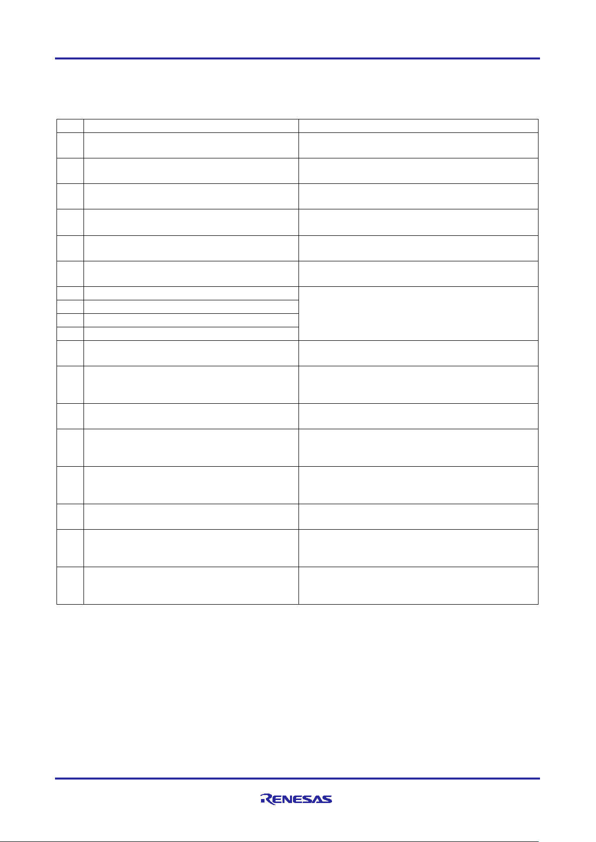
6.2 MQTT/TLS Application SW Architecture Overview
The following files from this application project serve as a reference
Table 3. Fi les Used in Application Project
(RTT) which allows real-time communication on
targets which support debugger memory accesses
while the CPU is running.
Hardware Abstraction Layer initialization and
operate the Wi-Fi module. This file For WiFi based
provided by usr_wifi.c. This file For WiFi
operate the FreeRTOS TCP/IP and Ethernet
provided by usr_network.c. This file is for the
R11AN0453EU0105 Rev.1.05 Page 12 of 12
Feb.11.21
Page 13
Renesas RA Family RA AWS MQTT/TLS Cloud Connectivity Solution
Step
Intermediate Steps
1
Project Creation:
File → New → C/C ++ Pr oject
2
Project Template:
Templates for New RA C/C++ Project →
Renesas RA C/C++ Project → Next
3
e2 studio - Project Configuration (RA
Project Name (Name for the Project)
Note: Input your desired name for the project -> Next
4
Device Selection →
FSP Version: 2.2.0
Board: EK-RA6M3
Device: R7FA6M3AH3CFC
Language: C
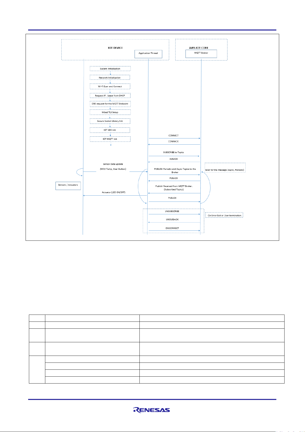
Figure 9. Application Example Implementation Details
Note: For Ethernet application example implementation in the Figure 9. “Wi-Fi scan and connect block” is
not applicable.
6.3 Crea ti ng the Application Project using the FSP Configurator
Complete steps to create the Project from the start using the e2 studio and FSP configurator. The table below
shows the step-by-step process in creating the Project. It is assumed that the user is familiar with the
2
studio and FSP configurator. Launch the installed e2 studio for the FSP.
e
Table 4. Step-by-step Details for Creating the Application Project for Ethernet and Wi-Fi (EK-RA6M3)
C Executable Project) →
R11AN0453EU0105 Rev.1.05 Page 13 of 13
Feb.11.21
Page 14
Renesas RA Family RA AWS MQTT/TLS Cloud Connectivity Solution
Step
Intermediate Steps
5
Select Tools
Toolchain: GNU ARM Embedded (Default)
Toolchain version: (9.2.1.20191025)
Debugger: J-Link ARM
Next→
6
Build Artifact and RTOS Selection
Artifact Selection: Executable
RTOS Selection : FreeRTOS → Next
Project Template
Project Template Selection: FreeRTOS – Minimal – Static
Allocation → Finish
7
Stacks Tab (Part of the FSP
Configurator)→
Threads → New Thread
8
Config Thread Properties→
Symbol: application_thread
Name: Application Thread
Stack size: 8192 Bytes
Priority: 3
Thread Context: NULL
Memory Allocation: Static
9
Generic RTOS configs under thread (Additional configuration on top of the Default Config
provided by FSP)
Common → General
Use Mutex: Enabled
Use Recursive Mutexes: Enabled
Max Task Name Len: 32
Common → Memory Allocation
Support Dynamic Allocation: Enabled
Total Heap Size: 0x20000
10
Add the Heap Implementation in HAL/Common
New Stack →
FreeRTOS → Memory Management→ Heap 4
11
Adding the MQTT Client Module to the Thread
Note: Now the Newly created thread (Application thread) is ready to add new Stack (Here the MQTT
New Stack →
FreeRTOS → Libraries → AWS MQTT Client
12
Configuring the “AWS IoT Common” Module (Additional configuration on top of the Default
Config provided by FSP)
Properties → Common →
Platform Name: "AWS Cloud Connectivity".
Note: Few of the sections in this table are specific to Wi-Fi and Ethernet Implementation. Other
sections are common to both Wi-Fi and Ethernet. They are listed here for quick reference.
Common to both Wi-Fi and Ethernet :
Step number : 1-12, 14,15
Specific to Ethernet:
Step number : 13b,19,20,21
Specific to Wi-Fi:
Step number : 13a,16,17,18,23
13
Adding the Secure Socket Implementation. Implementation is available for 1) Wi-Fi (“Secure
Socket on WiFi”) or 2) Ethernet (“Secure Socket on FreeRTOS Plus TCP”).
13a
If your Application is with Wi-Fi
Implementation →
New → “Secure Socket on WiFi”
13b
If your Application is with Ethernet, add
New → “Secure Socket on FreeRTOS Plus TCP”
14
Adding Persistent storage support for AWS PKCS11 and resolve the error in the configurator
by selecting the Heap size in the BSP Tab
Add AWS PKCS11 PAL module →
New → AWS PKCS11 PAL on LittleFS
BSP Tab → RA Common→
Heap size : 0x1000
Client is added)
Module, add Secure Sockets for Wi-Fi
Secure Sockets for Ethernet
Implementation →
Note: For Ethernet application Total Heap Size: 0x40000
R11AN0453EU0105 Rev.1.05 Page 14 of 14
Feb.11.21
Page 15
Renesas RA Family RA AWS MQTT/TLS Cloud Connectivity Solution
Step
Intermediate Steps
15
Some dependency related to TLS Support are needed to be resolved to remove the error in the
FSP configurator by modifying the “Mbed Crypto” Property Settings.
Common → Platform →
MBEDTLS_PLATFORM_MEMORY : Define
Common → General →
MBEDTLS_THREADING_C : Define
Common → General →
MBEDTLS_THREADING_ALT : Define
Common → Public Key Cryptography
(PKC)→
ECC → MBEDTLS_ECDH_C : Define
16
Resolve the dependency for the Wi-Fi on-chip Silex Driver using “r_sci_uart” Module.
Configuring the Wi-Fi on-chip Silex Driver using r_sci_uart
Common →
Number of supported Socket instances: 1
Module Reset Port: 08
Module Reset Pin: 00
17
UART Driver r_sci_uart configuration
Note: This is only applicable for Wi-Fi application project.
Common →
FIFO Support: Enable
DTC Support: Enable
Flow control Support: Disable
Module Driver →
General → Channel: 9 (For PMOD 1)
Baud → Baud Rate: 115200
Flow Control →
Flow Control → Pin control: Disabled
Flow Control → RTS Port: Disabled
Flow Control → RTS Pin: Disabled
Interrupts→
Interrupts →
Transmit Data Empty Interrupt Priority: Priority 5
Interrupts →
Interrupts →
Error Interrupt Priority: Priority 5
18
Add DTC driver to complete the DTC Driver support for th e UART.
Add DTC driver for Transmission →
New → Transfer Driver on r_dtc
Add DTC driver for Reception →
New → Transfer Driver on r_dtc
19
FreeRTOS + TCP Configuration
same, except few of the default configuration needs to be changed
Common →
DHCP callback function → Enable
Note: This is only applicable for Wi-Fi application project.
Note: For Multiple socket connection using this Wi-Fi Module, 2 UARTS needs to be used. Even
though the Wi-Fi Module provides 2 UARTs (For Multiple Sockets) The Pmod connector only exposes
1 UART connectivity.
Therefore, in this case, if the requirement is to use in the multi socket mode, proper wiring needs to be
taken care to route the UART connection the Wi-Fi Module.
Note: In case of MQTT Connectivity example project, the connections can be managed with 1 Socket
connection only, and hence the socket instance is chosen as 1.
UART driver needs to be configured based on the data transmission and receive requirements
such as speed, FIFO, DTC support, Flow control, handling of UART interrupts etc.
CTS/RTS Selection: RTS(CTS is disabled)
Receive Interrupt Priority: Priority 5
Transmit End Interrupt Priority: Priority 5
Note: This is only applicable for Wi-Fi application project.
Note: This is only applicable for Ethernet application project. Most of the Default settings remain the
R11AN0453EU0105 Rev.1.05 Page 15 of 15
Feb.11.21
Page 16

Step
Intermediate Steps
Let TCP use windowing mechanism → Enable
20
Ethernet Driver Configuration
General →
Flow control functionality → Enable
Buffers →
Number of Tx Buffers → 4
Number of Rx Buffers → 4
21
Ether PHY Driver
Module g_ether_phy0 →
PHY LSI Address → 1
22
Adding the HAL Modules as required for the Application Project: Here, ADC, Timer0, Timer1,
read respectively.
HAL/Common Stacks → New Stack
Driver→ Input → External IRQ Driver on r_icu
Property Settings for r_icu
Name: pushButtonS1
Channel: 13
Trigger: Rising
Digital Filtering: enabled
Digital Filtering Sample Clock (PCLK/64)
Pin Interrupt Priority: Priority 10
Callback: pb_callback
HAL/Common Stacks → New Stack
Driver → Input → External IRQ Driver on r_icu
Property Settings for r_icu
Name: pushButtonS2
Channel: 12
Trigger: Rising
Digital Filtering: enabled
Digital Filtering Sample Clock (PCLK/64)
Pin Interrupt Priority: Priority 10
Callback: pb_callback
HAL/Common Stacks → New Stack
Driver → Timers → Timer Driver on r_gpt
Property Settings for r_gpt → General
Name: gpt
Channel: 0
Mode: Periodic
Period: 30
Period Unit: Seconds
Interrupts:
Callback: NULL
Overflow/Crest Interrupt Priority: Priority 10
HAL/Common Stacks → New Stack
Driver → Timers → Timer Driver on r_gpt
Property Settings for r_gpt → General
Name: g_hb_timer
Channel: 1
Mode: Periodic
Period: 1000
Period Unit: MilliSeconds
Interrupts:
Callback: g_hb_timer_cb
Overflow/Crest Interrupt Priority: Priority 10
HAL/Common Stacks → New Stack
Drivers → System → ELC Driver on r_elc
Property Settings for r_elc → Module
g_elc Driver on r_elc
Name: g_elc
HAL/Common Stacks → New Stack
Drivers → Analog → ADC Driver on r_adc
Property Settings for r_adc → General
Name: adc
Unit: 0
Resolution: 12-bit
Renesas RA Family RA AWS MQTT/TLS Cloud Connectivity Solution
External IRQ and ELC Modules are used for MCU Temperature, 30 Seconds periodic timer, 1
second Periodic Heartbeat Monitor Timer, P ush button switches, and Event linking of ADC Data
R11AN0453EU0105 Rev.1.05 Page 16 of 16
Feb.11.21
Page 17

Renesas RA Family RA AWS MQTT/TLS Cloud Connectivity Solution
Step
Intermediate Steps
Alignment: Right
Clear after read: On
Mode: Single Scan
Double-trigger: Disable d
Property Settings for r_adc → Input →
Channel Scan Mask : Temperature Sensor
Property Settings for r_adc → Interrupt
→
Normal/Group A Trigger: GPT0 COUNTER
OVERFLOW(overflow)
Callback: adc_mcu_temp_callback
Scan End Interrupt Priority: Priorit y 10
23
Modifying the Pin configuration as required for the Application Projects (UART related Pins,
used, so disable it.
Pins Tab in the FSP configurator →
Peripherals→ Graphics: GLCDC → GLCDC0
Operation Mode: Disabled
Peripherals → Connectivity: SCI → SCI9
Pin Group Selection: _A only
Operation Mode: Custom
TXD_MOSI : P203
RXD_MISO: P202
SCK : None
CTS_RTS_SS: None
SDA: None
SCL: None
24
Modifying the BSP Settings - RA Common for (Main stack and Heap Settings)
Property Settings for RA Common
Main stack size(bytes) : 0x1000
Heap size (bytes) : 0x1000
25
Adding FreeRTOS Objects for the Application (Topic Queue needs to be created for the
application – Message Queue)
Stacks Tab → Objects →
New Object → Queue
Property Settings for the Queue
Symbol: g_topic_queue
Item Size (Bytes): 64
Queue Length (Items): 16
Memory Allocation: Static
Step
Intermediate Steps
1
Project Creation:
File → New → C/C++ Project
2
Project Template:
Templates for New RA C/C++ Project →
Renesas RA C/C++ Project → Next
3
e2 studio - Project Configuration
(Renesas RA C/C++ Project) →
Project Name (Name for the Project)
4
Device Selection →
FSP Version: 2.2.0
Board: EK-RA6M4
Device: R7FA6M4AF3CFB
RTOS: FreeRTOS
Flow Control Pins, Disable Multi functionality pins as needed to use alternative pin functions).
Note: The GLCDC Pins are shared with SCI9 (PMOD 1), In this Application Project GLCDC is not
Table 5. Step-by-step Details for Creating the Application Project on RA6M4 (for Wi-Fi)
(Input the name of the project in the Window)
R11AN0453EU0105 Rev.1.05 Page 17 of 17
Feb.11.21
Page 18

Renesas RA Family RA AWS MQTT/TLS Cloud Connectivity Solution
Step
Intermediate Steps
5
Language
Language: C
6
Select Tools
Toolchain: GNU ARM Embedded (Default)
Toolchain version: (9.2.1.20191025)
Debugger: J-Link ARM
7
Project Type Selection
Flat (Non-TrustZone) Project→ Next
8
Build Artifact and RTOS Selection
Build Artifact Selection : Exec utab le
9
Project Template Selection
FreeRTOS – Minimal – Static Allocation → Finish
10
Stacks Tab (Part of the FSP
Configurator)→
Threads → New Thread
11
Config Thread Properties→
Symbol: application_thread
Name: Application thread
Stack size: 8192 Bytes
Priority: 1
Thread Context: NULL
Memory Allocation: Static
12
Generic RTOS configs under thread (Additional configuration on top of the Default Config
provided by FSP)
Common → General
Use Mutex: Enabled
Max Task Name Len : 32
Use Mutexes: Enabled
Use Recursive Mutexes: Enabled
Common → Memory Allocation
Support Dynamic Allocation: Enabled
Total Heap Size: 0x2b000
13
Add the Heap Implementation in HAL/Common
New Stack →
FreeRTOS → Memory Management→ Heap 4
14
Adding the MQTT Client Module to the Thread
Note: Now the Newly created thread (Application thread) is ready to add new Stack (Here the MQTT
New Stack →
FreeRTOS → Libraries → AWS MQTT Client
15
Configuring the “AWS IoT Common” Module (Additional configuration on top of the Default
Config provided by FSP)
Properties → Common →
Platform Name: "AWS Cloud Connectivity".
16
Adding the Secure Socket Implementation. Implementation is available for 1) Wi-Fi (“Secure
Socket on WiFi”) or 2) Ethernet (“Secure Socket on FreeRTOS Plus TCP”).
16a
If your Application is with Wi-Fi
Implementation →
New → “Secure Socket on WiFi”
17
Adding Persistent storage support for AWS PKCS11 and resolve the error in the configurator
by selecting the Heap size in the BSP Tab
Add AWS PKCS11 PAL module →
New → AWS PKCS11 PAL on LittleFS
BSP Tab → RA Common→
Heap size : 0x1000
18
Some dependency related to TLS Support are needed to be resolved to remove the error in the
FSP configurator by modifying the “Mbed Crypto” Property Settings.
Common → Platform →
MBEDTLS_PLATFORM_MEMORY : Define
Common → General →
MBEDTLS_THREADING_C : Define
Common → General →
MBEDTLS_THREADING_ALT : Define
Common → Public Key Cryptography
(PKC)→
ECC → MBEDTLS_ECDH_C : Define
Next→
RTOS Selection: FreeRTOS → Next
Client is added)
Module, add Secure Sockets for Wi-Fi
R11AN0453EU0105 Rev.1.05 Page 18 of 18
Feb.11.21
Page 19

Renesas RA Family RA AWS MQTT/TLS Cloud Connectivity Solution
Step
Intermediate Steps
19
Resolve the dependency for the Wi-Fi on-chip Silex Driver using “r_sci_uart” Module.
Configuring the Wi-Fi on-chip Silex Driver using r_sci_uart
Common →
Number of supported Socket instances: 1
Module Reset Port: 03
Module Reset Pin: 11
20
UART Driver r_sci_uart configuration
Note: This is only applicable for Wi-Fi application project.
Common →
FIFO Support: Enable
DTC Support: Enable
Flow control Support: Disable
Module Driver →
General → Channel: 9 (For PMOD 1)
Baud → Baud Rate: 115200
Flow Control →
CTS/RTS Selection: RTS(CTS is disabled)
UART Communication mode: RS232
Flow Control → Pin control: Disabled
Flow Control → RTS Port: Disabled
Flow Control → RTS Pin: Disabled
Interrupts→
Interrupts →
Transmit Data Empty Interrupt Priority: Priority 5
Interrupts →
Transmit End Interrupt Priority: Priority 5
Interrupts →
Error Interrupt Priority: Priority 5
21
Add DTC driver to complete the DTC Driver support for th e UART.
Add DTC driver for Transmission →
New → Transfer Driver on r_dtc
Add DTC driver for Reception →
New → Transfer Driver on r_dtc
22
Adding the HAL Modules as required for the Application Project: Here, ADC, Timer0, Timer1,
read respectively.
HAL/Common Stacks → New Stack
Driver→ Input → External IRQ Driver on r_icu
Property Settings for r_icu
Name: pushButtonS1
Channel: 10
Trigger: Rising
Digital Filtering: enabled
Digital Filtering Sample Clock (PCLK/64)
Note: This is only applicable for Wi-Fi application project.
Note: For Multiple socket connection using this Wi-Fi Module, 2 UARTS needs to be used. Even
though the Wi-Fi Module provides 2 UARTs (For Multiple Sockets) The Pmod connector only exposes
1 UART connectivity.
Therefore, in this case, if the requirement is to use in the multi socket mode, proper wiring needs to be
taken care to route the UART connection the Wi-Fi Module.
Note: In case of MQTT Connectivity example project, the connections can be managed with 1 Socket
connection only, and hence the socket instance is chosen as 1.
UART driver needs to be configured based on the data transmission and receive requirements
such as speed, FIFO, DTC support, Flow control, handling of UART interrupts etc.
Receive Interrupt Priority: Priority 5
Note: This is only applicable for Wi-Fi application project.
External IRQ and ELC Modules are used for MCU Temperature, 30 Seconds periodic timer, 1
second Periodic Heartbeat Monitor Timer, P ush button switches, and Event linking of ADC Data
R11AN0453EU0105 Rev.1.05 Page 19 of 19
Feb.11.21
Page 20

Renesas RA Family RA AWS MQTT/TLS Cloud Connectivity Solution
Step
Intermediate Steps
Pin Interrupt Priority: Priority 10
Callback: pb_callback
HAL/Common Stacks → New Stack
Driver → Input → External IRQ Driver on r_icu
Property Settings for r_icu
Name: pushButtonS2
Channel: 11
Trigger: Rising
Digital Filtering: enabled
Digital Filtering Sample Clock (PCLK/64)
Pin Interrupt Priority: Priority 10
Callback: pb_callback
HAL/Common Stacks → New Stack
Driver → Timers → Timer Driver on r_gpt
Property Settings for r_gpt → General
Name: gpt
Channel: 0
Mode: Periodic
Period: 30
Period Unit: Seconds
Interrupts:
Callback: NULL
Overflow/Crest Interrupt Priority: Priority 10
HAL/Common Stacks → New Stack
Driver → Timers → Timer Driver on r_gpt
Property Settings for r_gpt → General
Name: g_hb_timer
Channel: 1
Mode: Periodic
Period: 1000
Period Unit: MilliSeconds
Interrupts:
Callback: g_hb_timer_cb
Overflow/Crest Interrupt Priority: Priority 10
HAL/Common Stacks → New Stack
Drivers → System → ELC Driver on r_elc
Property Settings for r_elc → Module
Name: g_elc
HAL/Common Stacks → New Stack
Drivers → Analog → ADC Driver on r_adc
Property Settings for r_adc → General
Name: adc
Unit: 0
Resolution: 12-bit
Alignment: Right
Clear after read: On
Mode: Single Scan
Double-trigger: Disable d
Property Settings for r_adc → Input →
Channel Scan Mask : Temperature Sensor
Property Settings for r_adc → Interrupt
→
Normal/Group A Trigger: GPT0 COUNTER
OVERFLOW(overflow)
Callback: adc_mcu_temp_callback
Scan End Interrupt Priority: Priorit y 10
23
Modifying the Pin configuration as required for the Application Projects (UART related P ins,
Flow Control Pins).
Pins Tab in the FSP configurator →
Peripherals → Connectivity: SCI → SCI9
Pin Group Selection: Mixed
Operation Mode: Asynchronous UART
Input/Output →
TXD_MOSI : P203
RXD_MISO: P202
g_elc Driver on r_elc
R11AN0453EU0105 Rev.1.05 Page 20 of 20
Feb.11.21
Page 21

Renesas RA Family RA AWS MQTT/TLS Cloud Connectivity Solution
Step
Intermediate Steps
SCK : None
CTS_RTS_SS: None
SDA: None
SCL: None
24
Modifying the BSP Settings - RA Common for (Main stack and Heap Settings)
Property Settings for RA Common
Main stack size(bytes) : 0x1000
Heap size (bytes) : 0x1000
25
Adding FreeRTOS Objects for the Application (Topic Queue needs to be created for the
application – Message Queue)
Stacks Tab → Objects →
New Object → Queue
Property Settings for the Queue
Symbol: g_topic_queue
Item Size (Bytes): 64
Queue Length (Items): 16
Memory Allocation: Static
Property
Original Value
Changed Value
Reason for Change
Application Thread
Common → General → Use
Disabled
Enabled
This requirement is set by the
Common → Memory Allocation
→ Support Dynamic Allocation
Disabled
Enabled
This requirement is set by the
AWS IOT SDK C stack
Common → Memory Allocation
0
0x20000
Heap required for the
AWS IoT Common
Common → IoT Thread
512
4096
This stack size is for the
stack than the default size.
The above configuration is a prerequisite to generate the required Stack and features for the Cloud
connectivity application provided with this app note. Once the ‘Generate Project Content’ button is clicked, it
generates the source code for the project. The generated source code contains the required drivers, stack
and middleware. The user application files are required to be added into the src folder.
Note: FSP generated Code needs to be called/used from the application, while some of the middleware
needs to be called exclusively as part of the application for proper initialization. For instance
“mbed_tls_setup()” call initializes the SCE and TRNG; SYSTEM_Init() initializes and prepares
the Crypto and Socket Libraries and IotSdk_Init() initializes and prepares the IOT libraries.
For the validation of the created project, the same source files listed in the section MQTT/TLS Application
SW Architecture Overview (Table 3) may be added.
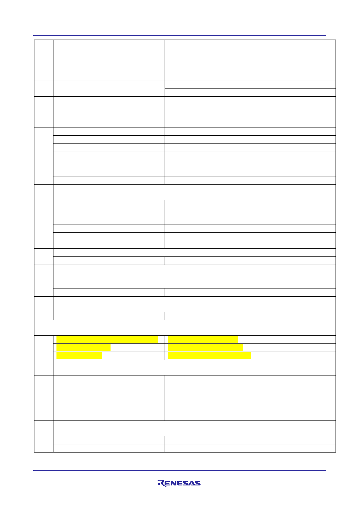
The Details of the configurator from the default settings to changed settings are described in the
following sections, including the reason for change.
6.4 MQTT/TLS Configur ation
This section describes the MQTT and TLS module configuration settings that are done as part of this
application example.
The following table lists changes made to a default configuration populated by the RA Configurator.
Table 6. Default C on figuration for EK-RA6M3
Mutexes
→ Total Heap Size
AWS IOT SDK C stack
FreeRTOS, AWS IOT SDK,
Mbed TLS
Default Stack Size
R11AN0453EU0105 Rev.1.05 Page 21 of 21
Feb.11.21
internal IoT thread. The
Application requires more
Page 22

Renesas RA Family RA AWS MQTT/TLS Cloud Connectivity Solution
Common → IoT Network
512
4096
This stack size is for the
Platform Name
Unknown
AWS Cloud
Connectivity
This value is user selectable
and can be set to any value.
Wi-Fi Specific only
Wi-Fi On-chip Silex Driver
Common → Number of Socket
16 1 For MQTT, only 1 socket is
application.
Module Reset Port
06
08
Supported Port on PMOD 1
Module Reset Pin
03
00
Supported Pin on PMOD 1
provided Pin.
Wi-Fi Specific only
UART Driver
Common → FIFO Support
Disabled
Enabled
Allows buffering of received
data, to avoid packet loss.
Common → DTC Support
Disabled
Enabled
Using the Data Transfer
Common → RS232/RS485
Disabled
Disabled
Flow control is required for
overwhelming the receiver.
General → Channel
0 9 The PMOD 1 for the Silex Wi-
Interrupts → Receive Interrupt
Priority
Priority 12
Priority 5
Data Receive and Transmit are
given higher priority.
Interrupts → Transmit Data
Priority 12
Priority 5
Interrupts → Transmit End
Interrupt Priority
Priority 12
Priority 5
Interrupt → Error Interrupt
Priority 12
Priority 5
Transfer Driver for TXI
Not Used
Used
Use of the Data Transfer
and receive information.
Receive Task Stack Size
Instances Supported
internal Network Receive
thread. The Application
requires more stack than the
default size.
needed. However, to use more
than 1 socket, a second UART
must be opened and used.
Currently multiple sockets are
not supported in this
changed from the default BSP
provided Port.
changed from the default BSP
Flow Control
Empty Interrupt Priority
Priority
Controller reduces the CPU
overhead required to transmit
and receive information.
higher baud rate/data rates.
This is Good practice to
prevent the incoming data from
Fi is physically connected to
Serial Communication
Interface channel 9 on EKRA6M3
Controller reduces the CPU
overhead required to transmit
R11AN0453EU0105 Rev.1.05 Page 22 of 22
Feb.11.21
Page 23
Renesas RA Family RA AWS MQTT/TLS Cloud Connectivity Solution
Transfer Driver for RXI
Not Used
Used
Use of the Data Transfer
Common to both Wi-Fi and Ethernet
Mbed Crypto
Platform →
Undefine
Define
This selection is required in
General →
mbedtls_deprecated_removed
Define
Undefine
General →
Define
Undefine
General →
Undefine
Define
This selection is required in
to plug in any thread library.
General →
Undefine
Define
This selection is required in
Public Key Cryptography →
Undefine
Define
This selection is required in
to enable the ECDH module.
LittleFS (Heap Selection)
BSP → RA Common Heap
Size
0x0
0x1000
Heap selection for Heap 3 and
below needs to be done here.
Ethernet Specific only:
FreeRTOS + TCP
Common → DHCP Callback
function
Disable
Enable
Callback for DHCP handling
Let TCP use windowing
Disabled
Enable
Turns on the TCP Flow control
Ethernet Driver Configuration
BSP → RA Common Heap
0x0
0x1000
Heap selection for Heap 3 and
General → Flow control
functionality →
Disable
Enable
Flow control selection for
Ethernet
Buffers → Number of Tx
1 4 Tx Buffer for Data Transmit
Buffers → Number of Rx
Buffers →
1 4 Rx Buffer for Data Reception
Ethernet PHY Driver
Module g_ether_phy0 →
0 1 Select the LSI PHY Address
Property
Original Value
Changed Value
Reason for Change
Application Thread
Common → General → Use
Disabled
Enabled
This requirement is set by the
Controller reduces the CPU
overhead required to transmit
and receive information.
mbedtls_platform_memory
mbedtls_check_params
mbedtls_threading_alt
mbedtls_threading_c
ECC → mbedtls_ecdh_c
Configuration
order to support the mbed_tls.
order to support the mbed_tls
order to support the mbed_tls
to abstracts the threading layer
to allow easy plugging in any
thread-library.
order to support the mbed_tls
mechanism →
Size
Buffers →
Table 7. Default Configuration for EK-RA6M4
Mutexes
R11AN0453EU0105 Rev.1.05 Page 23 of 23
Feb.11.21
below needs to be done here.
AWS IOT SDK C stack
Page 24

Renesas RA Family RA AWS MQTT/TLS Cloud Connectivity Solution
Property
Original Value
Changed Value
Reason for Change
Common → Memory Allocation
→ Support Dynamic Allocation
Disabled
Enabled
This requirement is set by the
AWS IOT SDK C stack
Common → Memory Allocation
0
0x2b000
Heap required for the
AWS IoT Common
Common → IoT Thread
512
4096
This stack size is for the
stack than the default size.
Common → IoT Network
512
4096
This stack size is for the
Platform Name
Unknown
AWS Cloud
Connectivity
This value is user selectable
and can be set to any value.
Wi-Fi Specific only
Wi-Fi On-chip Silex Driver
Common → Number of Socket
16 1 For MQTT, only 1 socket is
application.
Module Reset Port
06
03
Supported Port on PMOD 1
Module Reset Pin
03
11
Supported Pin on PMOD 1
provided Pin.
Wi-Fi Specific only
UART Driver
Common → FIFO Support
Disabled
Enabled
Allows buffering of received
data, to avoid packet loss.
Common → DTC Support
Disabled
Enabled
Using the Data Transfer
Common → RS232/RS485
Disabled
Disabled
Flow control is required for
overwhelming the receiver.
General → Channel
0 9 The PMOD 1 for the Silex Wi-
Interrupts → Receive Interrupt
Priority 12
Priority 5
Data Receive and Transmit are
→ Total Heap Size
Default Stack Size
Receive Task Stack Size
Instances Supported
FreeRTOS, AWS IOT SDK,
Mbed TLS
internal IoT thread. The
Application requires more
internal Network Receive
thread. The Application
requires more stack than the
default size.
needed. However, to use more
than 1 socket, a second UART
must be opened and used.
Currently multiple sockets are
not supported in this
Flow Control
changed from the default BSP
provided Port.
changed from the default BSP
Controller reduces the CPU
overhead required to transmit
and receive information.
higher baud rate/data rates.
This is Good practice to
prevent the incoming data from
Fi is physically connected to
Serial Communication
Interface channel 9 on EKRA6M3
R11AN0453EU0105 Rev.1.05 Page 24 of 24
Feb.11.21
Page 25

Renesas RA Family RA AWS MQTT/TLS Cloud Connectivity Solution
Property
Original Value
Changed Value
Reason for Change
Priority
given higher priority.
Interrupts → Transmit Data
Priority 12
Priority 5
Interrupts → Transmit End
Interrupt Priority
Priority 12
Priority 5
Interrupt → Error Interrupt
Priority 12
Priority 5
Transfer Driver for TXI
Not Used
Used
Use of the Data Transfer
and receive information.
Transfer Driver for RXI
Not Used
Used
Use of the Data Transfer
Mbed Crypto
Platform →
mbedtls_platform_memory
Undefine
Define
This selection is required in
order to support the mbed_tls.
General →
Define
Undefine
General →
mbedtls_check_params
Define
Undefine
General →
Undefine
Define
This selection is required in
General →
Undefine
Define
This selection is required in
thread-library.
Public Key Cryptography →
Undefine
Define
This selection is required in
(Heap Selection in BSP Tab)
BSP → RA Common Heap
0x0
0x1000
Heap selection for Heap 3 and
Empty Interrupt Priority
Priority
Controller reduces the CPU
overhead required to transmit
Controller reduces the CPU
overhead required to transmit
and receive information.
mbedtls_deprecated_removed
mbedtls_threading_alt
mbedtls_threading_c
ECC → mbedtls_ecdh_c
Size
order to support the mbed_tls
to plug in any thread library.
order to support the mbed_tls
to abstracts the threading layer
to allow easy plugging in any
order to support the mbed_tls
to enable the ECDH module.
below needs to be done here.
6.4.1 IoT Cloud Configuration (AWS)
6.4.1.1 AWS IoT Policies
AWS IoT Core policies are JSON (JavaScript Object Notation) documents that authorize a device to perform
AWS IoT Core operations. AWS IoT defines a set of policy actions describing the operations and resources
for which access can be granted or denied. For example:
• IoT: Connect represents permission to connect to the AWS IoT message broker.
• IoT: Subscribe represents permission to subscribe to an MQTT topic or topic filter.
• IoT: GetThingShadow represents permission to get a ‘thing’ shadow.
JSON
JSON is an open standard, lightweight, data-interchange format. As a text document, it is easy for users to
read and write, and for machines to parse and generate.
R11AN0453EU0105 Rev.1.05 Page 25 of 25
Feb.11.21
Page 26

Renesas RA Family RA AWS MQTT/TLS Cloud Connectivity Solution
JSON is completely language independent, using conventions that are familiar to C-family programmers,
including C, C++, C#, Java, JavaScript, Perl, Python, and many others. The following example shows a
JSON script used to turn on an LED.
{
“LED_value”: “On”
}
AWS IoT Thing Shadow
A Thing Shadow (also referred to as a Device Shadow) is a JSON document used to store and retrieve
current state information for a Thing (device, application, and so on).
The Thing Shadow service maintains a thing shadow for each thing connected to AWS IoT Core. Thing
shadows may be used to get and set the state of a thing over MQTT or HTTP, regardless of whether the
thing is connected to the Internet. Each thing shadow is uniquely identified by its name.
Amazon Web Services Signup
Amazon Web Services offers a free account (12 months) for each user. It is expected that a user account
needs to be created on the AWS IoT Cloud service before continuing to the next section.
To create an AWS account, open to the following link in a web browser:
https://portal.aws.amazon.com/billing/signup#/start
Fill in the required details and create a user account.
Note: While creating the project, certificates and policies, the screenshots may look slightly different from
what is shown in the document and users need to use navigation in the AWS IoT core environment to
find corresponding attributes while working on this project.
6.4.2 Creating a Device on AWS IoT Core
The following steps detail how to create a device on the IoT Core user account. It is assumed that the user
account is created in the AWS IoT Core and the user has followed the AWS signup procedure.
6.4.2.1 Open AWS IoT Core Service
1. Connect to the AWS IoT service by typing IoT Core in the AWS services search bar.
2. Click IoT Core.
Figure 10. RA Cloud Connectivity AWS IOT Core Selection
6.4.2.2 Create a Thing
1. Start creating a device by selecting Manage. Be sure to select the appropriate re g ion in the AWS console
on the top right corner.
Note: A Thing created in one region will not be seen in another region.
2. Now select Things.
3. Next, select Register a thing to create a thing.
R11AN0453EU0105 Rev.1.05 Page 26 of 26
Feb.11.21
Page 27

Renesas RA Family RA AWS MQTT/TLS Cloud Connectivity Solution
Figure 11. Register a Thing
Note: If the AWS IoT Thing is registered and created in the past in your account and you have some
devices present already, you may not see the initial registering of the thing and its associated GUI as
shown in the Figure 11. In that case you may see the Thing creation GUI bit different. You may create
a New Thing using the snapshot as a reference shown in the Figure 12.
Figure 12. Create a Thing
R11AN0453EU0105 Rev.1.05 Page 27 of 27
Feb.11.21
Page 28

Renesas RA Family RA AWS MQTT/TLS Cloud Connectivity Solution
4. Then select the Create a single thing button.
Figure 13. Create a Single Thing
5. Enter the Thing Name. In the example, a Thing by name Thing_RA6 is being created.
Note: Remember to store the Thing Name. This information is required for future reference during
configuration.
6. Create a Thing type by clicking the Create a type button. This will open another pop-up window.
Figure 14. Create a Type
R11AN0453EU0105 Rev.1.05 Page 28 of 28
Feb.11.21
Page 29

Renesas RA Family RA AWS MQTT/TLS Cloud Connectivity Solution
7. Enter the Type Name and Description. Add the attributes by clicking the button Add another in the Set
searchable thing attributes section.
Figure 15. Add Attributes
R11AN0453EU0105 Rev.1.05 Page 29 of 29
Feb.11.21
Page 30

Renesas RA Family RA AWS MQTT/TLS Cloud Connectivity Solution
8. Add the attribute key and click the Create thing type button.
Figure 16. Create Thing Type
R11AN0453EU0105 Rev.1.05 Page 30 of 30
Feb.11.21
Page 31

Renesas RA Family RA AWS MQTT/TLS Cloud Connectivity Solution
9. Select the Thing Type and enter the attribute value. Click the Next button.
Figure 17. Create Attribute
R11AN0453EU0105 Rev.1.05 Page 31 of 31
Feb.11.21
Page 32
Renesas RA Family RA AWS MQTT/TLS Cloud Connectivity Solution
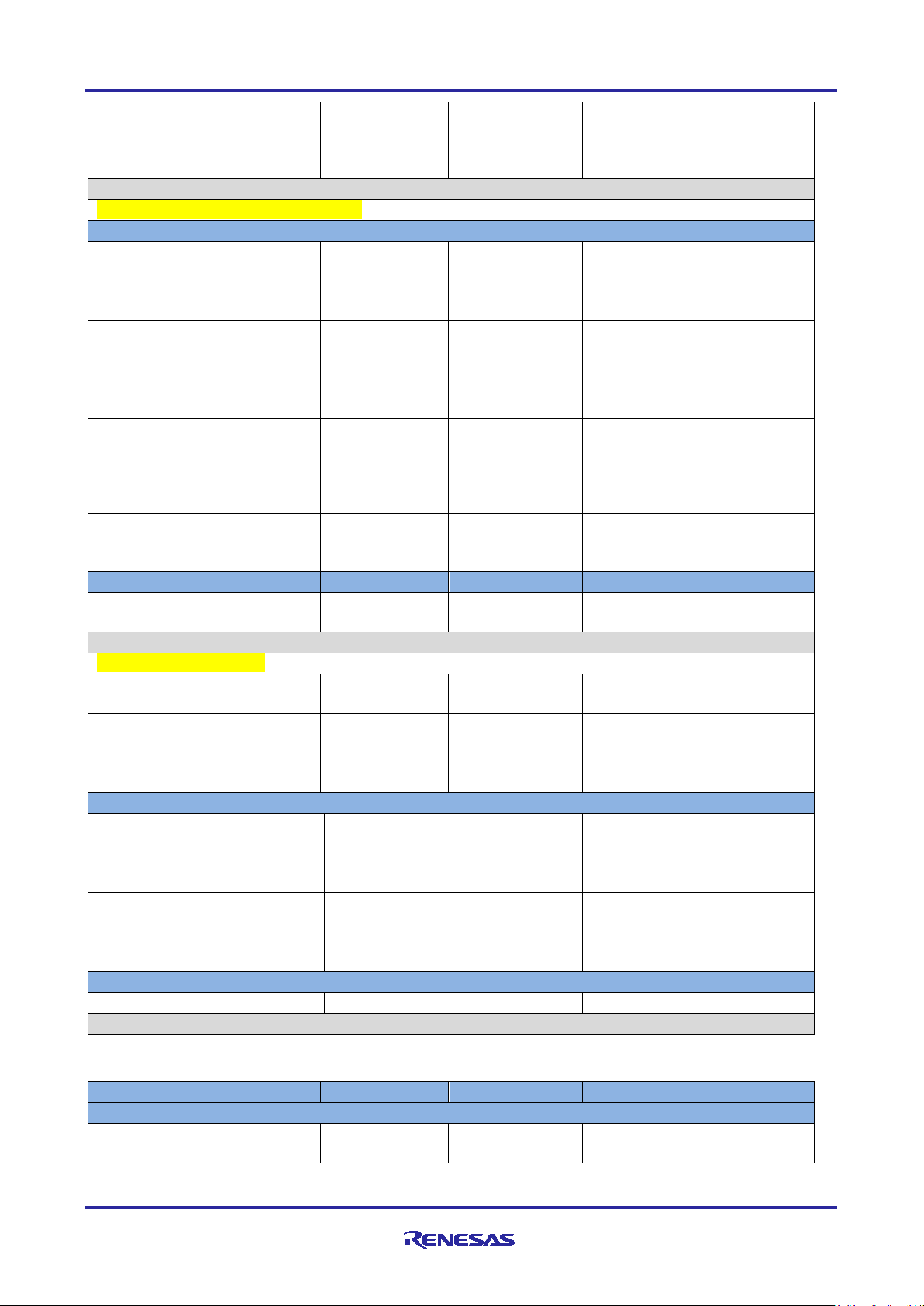
10. Click the option Create thing without certificate to create a thing in AWS IoT.
Figure 18. Create Thing without Certificate
6.4.3 Generating Device Certificate and Keys
At this point, it is assumed that the AWS IoT Thing has been created using the above instruc t ions. N o w,
generate device certificates and keys for the AWS IoT Thing (Thing) created.
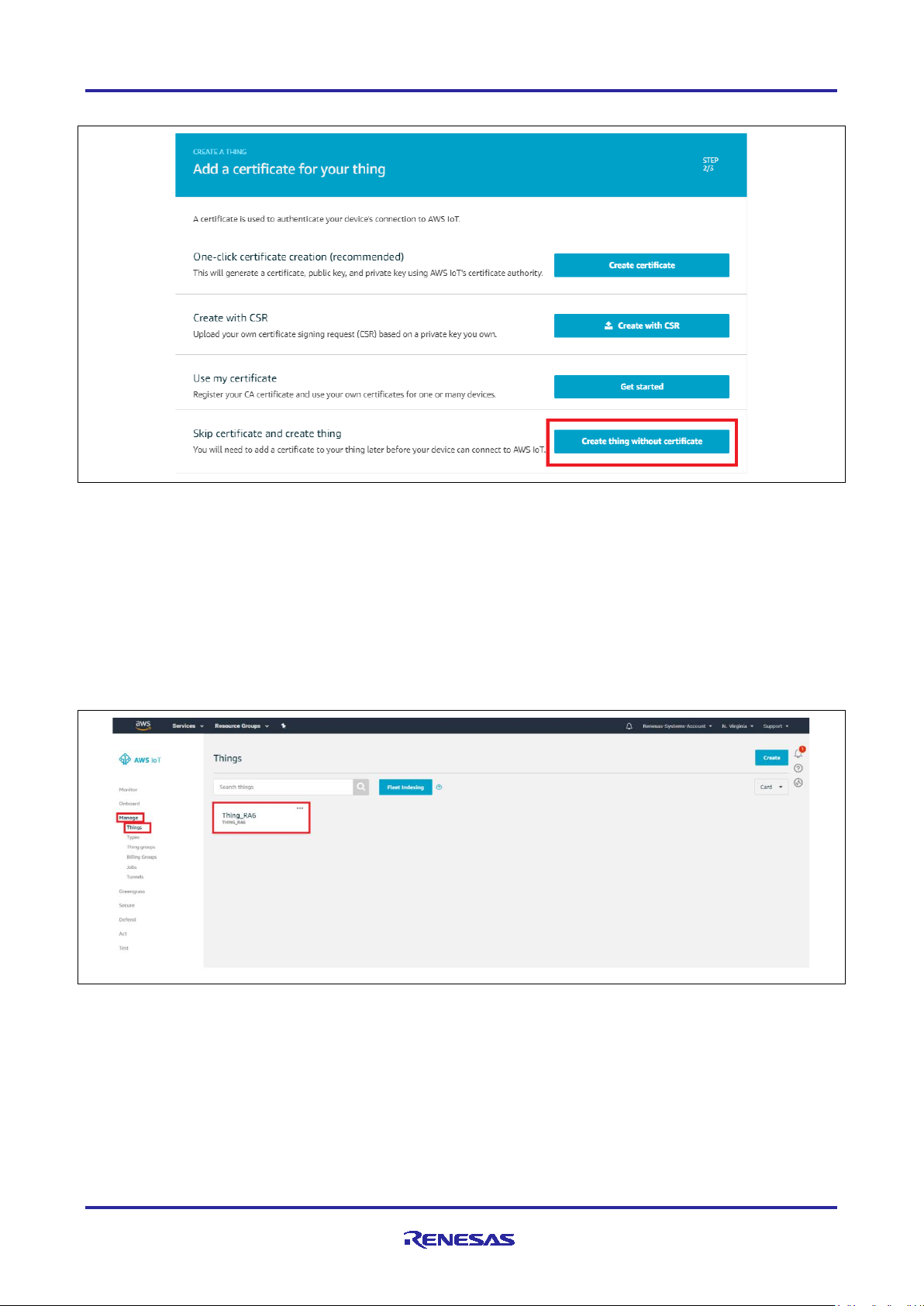
The Thing created appears in the Things section, as shown in the following screen.
Note: If the Things are created in the past in this account, it shows the new Thing created as part of the
existing Things as shown in the Figure 20.
Figure 19. Created Thing
R11AN0453EU0105 Rev.1.05 Page 32 of 32
Feb.11.21
Page 33

Renesas RA Family RA AWS MQTT/TLS Cloud Connectivity Solution
Figure 20. Created Things
1. Click the Thing created. It will open in a new window with the Thing information.
In the example, the Thing created is called Thing_RA6.
2. Go to the Security tab and click Create certificate button, as shown in the following screen .
Figure 21. Create Certificate on a new account
Note: If the Thing policy and certificates were created in the past on this account, the Certificate creation
GUI snapshot may look different, similar to the snapshot shown in Figure 22.
R11AN0453EU0105 Rev.1.05 Page 33 of 33
Feb.11.21
Page 34

Renesas RA Family RA AWS MQTT/TLS Cloud Connectivity Solution
Figure 22. Create Certificate on existing account
It generates the following for the Thing created, as shown in the following screen.
A device certificate,
A public key,
A private key,
A root CA for AWS IoT
3. To download certificates, click the Download button next to each of the certificates and keys, as shown in
the following screen.
Figure 23. Download Certificate
R11AN0453EU0105 Rev.1.05 Page 34 of 34
Feb.11.21
Page 35

Renesas RA Family RA AWS MQTT/TLS Cloud Connectivity Solution
4. Click the Download button. The root CA for AWS opens the link
https://docs.aws.amazon.com/iot/latest/developerguide/managing-device-certs.html#serverauthentication. Click RSA 2048 bit key: Amazon Root CA 1, as shown in the following Figure 24 to open
the certificate in a new tab.
Note: Certificate generated by right clicking and downloading it to the PC might not work.
Figure 24. Certificate Page
R11AN0453EU0105 Rev.1.05 Page 35 of 35
Feb.11.21
Page 36

Renesas RA Family RA AWS MQTT/TLS Cloud Connectivity Solution
5. Go back to the AWS console and click the Activate button to activate the certificate just created.
6. After certificate activation, click the Done button to complete the certification/keys creation.
Figure 25. Certificate Created
Note: Since October 2018, AWS has recommended that all users create an Amazon Trust Services (ATS)
endpoint and load these CA certificates onto their devices. The Amazon Root CA1 can be
downloaded from: https://docs.aws.amazon.com/iot/latest/developerguide/managing-device-
certs.html.
For users who created endpoints prior to October 2018 and are still using them to test this AP, it is
recommended to use the rootCA.pem file given as part of this package.
6.4.4 Creating a Policy for a Device
To create a policy, go back to the Thing Hub.
1. Click the Secure option shown in the following screen.
2. Click the Policies option, which opens a window to create a new policy.
3. Click the Create button in the policies window to create new policy.
Figure 26. New Policy Creation
Note: If the Thing and Policy were created in the past, the Policy creation GUI snapshot may look different
and is similar to the snapshot shown as follows.
R11AN0453EU0105 Rev.1.05 Page 36 of 36
Feb.11.21
Page 37

Renesas RA Family RA AWS MQTT/TLS Cloud Connectivity Solution
Figure 27. New Policy Creation with Existing Policies
4. Enter the name for the policy in the Name box as shown in the following screen.
5. Under Action, type: iot:*
6. Under Resource ARN, type: *
Note: The examples in this document are intended only for development environments. All devices in
your fleet must have credentials with privileges that authorize only intend ed ac tions on specific
resources. The specific permission policies can vary for your use case. Identify the permission
policies that best meet your business and security requirements. For more information, refer to
Example policies and Security best practices
.
7. Click Allow.
8. Click Create. The policy has now been created.
Figure 28. Create New Policy
R11AN0453EU0105 Rev.1.05 Page 37 of 37
Feb.11.21
Page 38

Renesas RA Family RA AWS MQTT/TLS Cloud Connectivity Solution
6.4.5 Connecting the Certificate to the Policy
1. Click the Secure option as shown in the following screen. Then, click the Certificates option. It will open
a window listing the device certificates created in AWS IoT Core service.
2. Choose the certificate created earlier for the Thing. This can be done by clicking the “…” in the top right
corner of the certificate.
3. Click the Attach policy option from the drop-down menu.
Figure 29. Connecting the Certificate to New Policy
Note: If the Thing and Policy were created in the past on this account, you may notice the existing
certificates. The Certificate attached to the policy GUI snapshot may look different, similar to the
snapshot shown in Figure 30.
Figure 30. Connecting the Certificate to New Policy
4. Search for the policy on the Search policies window.
5. Choose the policy from the list and click the Attach button, as shown in the following screen.
R11AN0453EU0105 Rev.1.05 Page 38 of 38
Feb.11.21
Page 39

Renesas RA Family RA AWS MQTT/TLS Cloud Connectivity Solution
6. The policy is now attached to the device certificate.
Note: If the Thing and Policy were created on an existing AWS account which already has existing
Things, the Certificate attached to the policy GUI snapshot may look different and is similar to the
snapshot shown in the Figure 32.
Figure 31. Attach Policies to Certificate
R11AN0453EU0105 Rev.1.05 Page 39 of 39
Feb.11.21
Page 40

Renesas RA Family RA AWS MQTT/TLS Cloud Connectivity Solution
Figure 32. Attach Policies to Certificate
6.5 Running the MQTT/ TLS Application Example
Note: If the project has been created with the instruction given in the previous section (6.3) using the FSP
configurator, skip importing of the Project and directly go to Loading the Executable Binary into the
Target MCU(6.5.2). However, to quickly import and evaluate the application project archived with this
document, browse the sub-sections below on Importing, building and loading sections.
6.5.1 Importing, Building and Loading the Project
6.5.1.1 Importing
This project can be imported into e2 studio using instructions provided in the RA FSP User’s Manual. See
Section Starting Deve lopment > e2 studio ISDE User Guide > Importing an Existing Project into e2 studio
ISDE.
6.5.1.2 Building the Latest Executable Binary
Upon successfully importing and/or modifying the project into e2 studio IDE, follow instructions provided in
the RA FSP User’s Manual to build an executable binary/hex/mot/elf file. See Section Starting Development
> e2 studio ISDE User Guide > Tutorial: Your First RA MCU Project > Build the Blinky Project.
Note: The attached Application Project Example may produce an error, if test credentials are used during
the run. Refer to the upcoming section: Connecting to AWS IoT to enter the credentials for the device
created per the section Creating a Device on AWS IoT Core.
R11AN0453EU0105 Rev.1.05 Page 40 of 40
Feb.11.21
Page 41

Renesas RA Family RA AWS MQTT/TLS Cloud Connectivity Solution
Board Name
Jumper settings
EK-RA6M3
No change necessary
EK-RA6M4
No change necessary
Board Name
Pmod Identifier
EK-RA6M3
PMOD 1 (J26)
EK-RA6M4
PMOD 1 (J26)
6.5.2 Loading the Executable Binary into the Target MCU
The executable file may be programmed into the target MCU through any one of three means.
6.5.2.1 Using a Debugging Interface with e2 studio
Instructions to program the executable binary are found in the latest RA FSP User Manual. See Section
Starting Development > e2 studio ISDE User Guide > Tutorial: Your First RA MCU Project > Debug the
Blinky Project.
This is the preferred method for programming as it allows for additional debugging functionality available
through the on-chip deb ugg er.
6.5.2.2 Using J-Link Tools
SEGGER J-Link Tools such as J-Flash, J-Flash Lite, and J-Link Commander can be used program the
executable binary into the target MCU. Refer User Manuals UM08001, and UM08003 on www.segger.com
6.5.2.3 Using Renesas Flash Programmer
The Renesas Flash Programmer provides usable and functional support for programming the on-chip flash
memory of Renesas microcontrollers in each phase of development and mass production. The software
supports all RA MCUs and the software user’s manual is available online [13].
6.5.3 Powering up the Board
To connect power to the board, connect the USB cable to the EK-RA6M3 board’s J10 connector
(DEBUG_USB) and the other end to the PC USB port, and run the debug application, using the following
instructions.
.
Reset the board assembly associated with this application note to the default electrical jumper settings as
specified in the board’s documentation, that is, the hardware us er’s m anual, bef ore proc ee di ng with the nex t
set of instructions.
6.5.3.1 Deviation from Default Jumper Settings
The following are deviations from default board settings that should be performed prior to applying power to
evaluate the application.
Table 8. Jumper Settings
6.5.3.2 Additional Components to Connect
For Wi-Fi based Cloud connectivity application project/note requires the user to connect the Silex SXULPGN-EVK Wi-Fi evaluation kit [14] to a Pmod connector.
Table 9. Additional Components
For Ethernet based Cloud connectivity application project/note, the user is required to connect the Ethernet
cable to the RJ45 Ethernet connector on the Board.
6.5.3.3 Power-on Behavior
Upon successful configuration and downloading of the image to the target RA MCU, the following behavior
should be observed upon application of power.
1. The power LED on the RA MCU target assembly lights up.
2. The J-Link LED will be blinking based on the activity when it is connected.
3. The User LED (BLUE, GREEN, RED) are used to indicate the status of the application from the start of
initialization to continuous status of running.
R11AN0453EU0105 Rev.1.05 Page 41 of 41
Feb.11.21
Page 42

Renesas RA Family RA AWS MQTT/TLS Cloud Connectivity Solution
6.6 Connecti ng to AWS IoT
This section describes the steps to be followed to connect the device to the AWS IoT.
With the necessary infrastructure is in place, it is necessary to input credentials for connecting to the 2.4GHz
Wi-Fi Access Point and AWS IoT.
Note: Firewalls in the network may prevent con necti v it y to AWS IoT. Configure the network to allow access
to the MQTT Port 8883.
6.6.1 Wi-Fi Credentials
Default credentials for Wi-Fi Connection are found in the file usr_config.h. These should be updated to
match the credentials needed for the Wi-Fi Access Point/Wi-Fi Router, that the board will connect to. The
default credentials which need to be changed in the code are as shown below.
#define WIFI_SSID "Renesas" “Change this to the correct network SSID”
#define WIFI_PW "Renesas123" “Change this to the correct network Password”
#define SECURITY "WPA2" User Options are: "Open", "WEP", "WPA","WPA2"
Note: Applicable to Wi-Fi application only.
6.6.2 AWS IoT Credentials
Default credentials for connectivity to AWS IoT are provided in the file usr_config.h These should be
updated to use the credentials generated per the guidelines provided in section Creating a Device on AWS
IoT Core. MQTT ENDPOINT is obtained from the AWS IoT Core. The screenshots for the reference to
capture the Endpoint information are as shown below.
#define USR_MQTT_ENDPOINT "aoh5lvd4o23ku-ats.iot.us-east-1.amazonaws.com"
Figure 33. Getting User MQTT Endpoint
R11AN0453EU0105 Rev.1.05 Page 42 of 42
Feb.11.21
Page 43

Renesas RA Family RA AWS MQTT/TLS Cloud Connectivity Solution
Downloaded Certificate/Key format from AWS
Desired Format for the AWS SDK
-----BEGIN PUBLIC KEY-----
“-----BEGIN PUBLIC KEY-----\n”\
The downloaded asymmetric key pairs and certificates generated from AWS need to be included into the
source code (usr_config.h) for the Application Example by converting each line into the format required
by the AWS SDK as shown below. Refer the src/usr_config.h from the attached project for more details.
#define SERVER_CERTIFICATE “Populate the New Server Certificate”
#define CLIENT_CERTIFICATE “Populate the Client Certificate”
#define CLIENT_KEY “Populate the Client Key”
6.7 Ver ifying the Application Project
This section describes the steps on how to verify this application example functionalities.
Upon successfully programming the target RA MCU with the application example binary and powering up the
board, a SEGGER J-Link RTT Console such as J-Link RTT Viewer V6.95a should display output similar to
the output shown below:
Note: If the user wants to use the SWO viewer for the Console instead of RTT Viewer, change the default
#define USR_LOG_TERMINAL (RTT_TERMINAL) to ITM_TERMINAL, and build the project.
Figure 34. Welcome Screen on the Console
R11AN0453EU0105 Rev.1.05 Page 43 of 43
Feb.11.21
Page 44
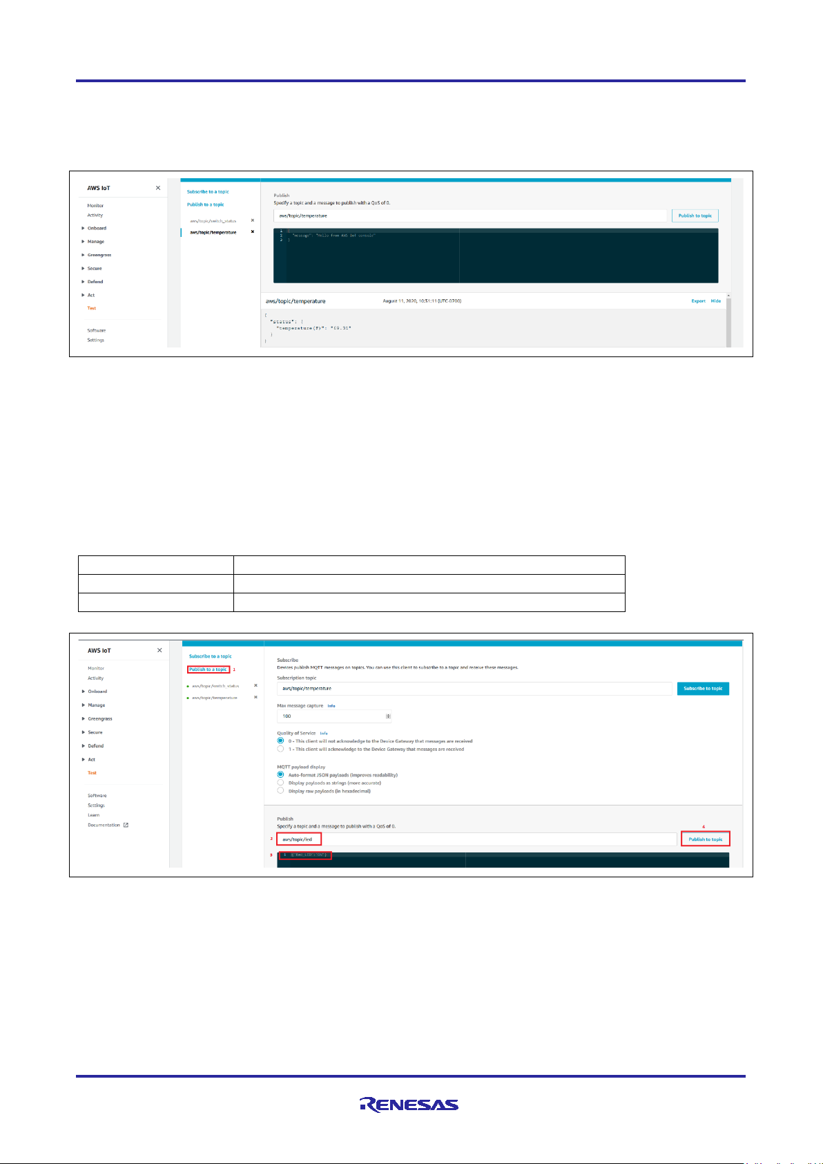
Renesas RA Family RA AWS MQTT/TLS Cloud Connectivity Solution
LED State
Message
RED LED ON
{"Red_LED":"ON"}
RED LED OFF
{"Red_LED":"OFF"}
On the Cloud side, go to IoT Core and select Test, then choose MQTT test client. Subscribe to a topic (In
this Application “aws/topic/temperature” and “aws/topic/switch_status” are the topics for subscription). You
may observe events on the dashboard for the subscribed topics as shown below.
Note: Temperature messages are synchronous (every 30 seconds). Switch status are Asynchronous.
Figure 35. Subscribed Messages on the AWS IoT Screen
To publish the message from the Cloud to the Device, in order to turn ON/OFF the LEDs, select Publish to a
topic and type the specific topic (“aws/topic/led”) and message in the respective window and click Publish
to a topic as shown below. Follow the steps 1-4 as shown in Figure 36.
The actuation of the requested LED can be seen on the demo board.
Note: The messages under Message column are ca se sen si t iv e; users need to take care of this while
using them to turn the LEDs ON/OFF.
Only enter one message at a time. Copy the message ‘as-is’ and do not include an y extra spaces .
Table 10. Messages for Toggling User LED
Note: The LEDS are also used for other user indications in this Application. So, you may see that the LED
R11AN0453EU0105 Rev.1.05 Page 44 of 44
Feb.11.21
Figure 36. Publishing the Messages from the AWS IoT Screen
status changes after you set the LED status from the MQTT GUI Publish to a topic due to the
following events.
Page 45

Renesas RA Family RA AWS MQTT/TLS Cloud Connectivity Solution
[1]
International Telecommunication Union, "ITU-T Y.4000/Y.2060 (06/2012)," 15 06 2012. [Online].
[2]
Amazon Web Services, "AWS IoT Core Features," [Online]. Available:
[3]
Amazon Web Services, "AWS IoT Core," [Online]. Available: https://www.amazonaws.cn/en/iot-core/.
[4]
W. T. L. L. O. S. R. N. S. R. X. G. K. N. K. S. F. M. K. D. L. I. R. Valerie Lampkin, Building Smarter
[5]
I. E. T. Force, "The Transport Layer Security (TLS) Protocol Version 1.2," [Online]. Available:
[6]
Amazon Web Services, "AWS IoT Security," [Online]. Available:
[7]
Amazon Web Services, "Trans port Secur ity in AWS IoT," [Online]. Available:
[8]
International Telecommunication Union, "X.509 (10/19) Summary," 10 2019. [Online]. Available:
[9]
Eclipse Foundation, "Eclipse Mosquitto™ - An open source MQTT broker," [Online]. Available:
[10]
Amazon Web Services, "AWS IoT Device SDK C: MQTT," [Online]. Available:
[11]
R. Barry, "Mastering the FreeRTOS™ Real Time Kernel," in A Hands-On Tutorial Guide, 2016.
[12]
A. I. D. S. C. Documentation, "AWS IoT Device SDK C: MQTT Functions," [Online]. Available:
[13]
Amazon, "Configuring the FreeRTOS Demos," [Online]. Available:
[14]
"Amazon FreeRTOS mbedTLS," [Online]. Available: https://github.com/aws/amazon-
[15]
Renesas Electronics Corporation, "Renesas Flash Programmer (Programming GUI) - Documentation,"
• Blinking red LED indicates the MQTT message failure activity is seen. This could be Message Publish or
Subscribe failure.
• Solid red LED indicates the initialization failed. The console log will have the appropriate log for the error
(if this is not turned on by the user as part of the publish message).
• Green LED blinks periodically to indicate the heartbeat of the system and healthy network connectivity.
• Blue LED toggles based on the MQTT activity (default: temperature data every 30 seconds). Here the
blue LED activity indicates that successful MQTT messages are being exchanged.
7. MQTT/TLS Module Next Steps
• For setting up a client using a device certificate signed by a preferred CA certificate, refer to the link:
https://docs.aws.amazon.com/iot/latest/developerguide/device-certs-your-own.html
• For using a self-signed certificate to configure AWS, refer to the link:
https://developer.amazon.com/docs/custom-skills/configure-web-service-self-signed-certificate.html
8. Cloud Connectivity References
Available: http://handle.itu.int/11.1002/1000/11559.
https://www.amazonaws.cn/en/iot-core/features/.
Planet Solutions with MQTT and IBM WebSphere MQ Telemetry, IBM Redbooks, 2012.
https://tools.ietf.org/html/rfc5246.
https://docs.aws.amazon.com/iot/latest/developerguide/iot-security.html.
https://docs.aws.amazon.com/iot/latest/developerguide/transport-security.html.
https://www.itu.int/dms_pubrec/itu-t/rec/x/T-REC-X.509-201910-I!!SUM-HTM-E.htm.
https://mosquitto.org/.
https://docs.aws.amazon.com/freertos/latest/lib-ref/c-sdk/mqtt/index.html.
https://docs.aws.amazon.com/freertos/latest/lib-ref/c-sdk/mqtt/mqtt_functions.html.
https://docs.aws.amazon.com/freertos/latest/userguide/freertos-configure.html.
freertos/blob/master/libraries/3rdparty/mbedtls/utils/mbedtls_utils.c.
[Online]. Available: https://www.renesas.com/us/en/products/software-tools/tools/programmer/renesasflash-programmer-programming-gui.html#documents.
R11AN0453EU0105 Rev.1.05 Page 45 of 45
Feb.11.21
Page 46

Renesas RA Family RA AWS MQTT/TLS Cloud Connectivity Solution
[16]
Silex Technology, Inc., "SX-ULPGN-EVK - Evaluation kit for Ultra-Low-Power Hostless Wi-Fi IoT
Module," [Online]. Available: https://www.silextechnology.com/connectivity-solutions/embeddedwireless/sx-ulpgn-evk.
Prerequisite : https://docs.aws.amazon.com/iot/latest/developerguide/iot-gs.html
understand the AWS IoT and its configuration.
. Please use this link to
9. Known Issues
This section talks about the known FSP and tool related issues. More details can be found at this link
(https://github.com/renesas/fsp/issues
)
R11AN0453EU0105 Rev.1.05 Page 46 of 46
Feb.11.21
Page 47

Renesas RA Family RA AWS MQTT/TLS Cloud Connectivity Solution
RA Product Information
renesas.com/ra
RA Product Support Forum
renesas.com/ra/forum
RA Flexible Software Package
renesas.com/FSP
Renesas Support
renesas.com/support
Website and Support
Visit the following vanity URLs to learn about key elements of the RA family, download components and
related documentation, and get support.
R11AN0453EU0105 Rev.1.05 Page 47 of 47
Feb.11.21
Page 48

Renesas RA Family RA AWS MQTT/TLS Cloud Connectivity Solution
Rev.
Date
Description
Page
Summary
1.00
Apr.24.20
—
First release document
1.01
Jun.08.20
—
Updated the AN for FSP 1.1.0
1.02
Aug 12.20
—
Added support for Ethernet
Sep 10.20
—
Added FSP 1.3.0 Support.
1.03
Jan.06.21
1, 2, 30,
Added links, note to the Introduction and Requir e d res our ces
to section 6.4.4, and updated text in section 6.7.
1.04
Jan.22.21
—
Updated section 1.5, section 6.3, section 6.4, section 6.5.3.1,
section 6.7, and added section 9.
1.05
Feb.11.21
—
Fixed typos in Introduction
Revision History
35
section. Added Using this Application Note section, added
note to the Prerequisites and Audience section, added note
R11AN0453EU0105 Rev.1.05 Page 48 of 48
Feb.11.21
Page 49

Corporate Headquarters
Contact information
www.renesas.com
Trademarks
of their respective owners.
Notice
1. Descriptions of circuits, software and other related information in this document are provided only to illustrate the operation of semiconductor products
and application examples. You are fully responsible for the incorporation or any other use of the circuits, software, and information in the design of your
product or system. Renesas Electronics disclaims any and all liability for any losses and damages incurred by you or third parties arising from the use
of these circuits, software, or information.
2. Renesas Elect ronics hereby expressl y discl aim s an y war ranties against and liability for infringement or any other claims involving patents, copyrights,
or other intellectual property rights of third parties, by or arising from the use of Renesas Electronics products or technical information described in this
document, including but not limited to, the product data, drawings, charts, programs, algorithms, and application examples.
3. No license, express, implied or otherwise, is granted hereby under any patents, copyrights or other intellectual property rights of Renesas Electronics
or others.
4. You shall not alter, modify, copy, or reverse engineer any Renesas Electronics product, whether in whole or in part. Renesas Electronics disclaims any
and all liability for any losses or damages incurred by you or third parties arising from such alteration, modification, copying or reverse engineering.
5. Renesas Electronics products are classified according to the following two quality grades: “Standard” and “High Quality”. The intended applications for
each Renesas Electronics product depends on the product’s quality grade, as indicated below.
"Standard": Computers; office equipment; communications equipment; test and measurement equipment; audio and visual equipment; home
"High Quality": Transportation equipment (automobiles, trains, ships, etc.); traffic control (traffic lights); large-scale communication equipment; key
Unless expressly designated as a high reliability product or a product for harsh environments in a Renesas Electronics data sheet or other Renesas
Electronics document, Renesas Electronics products are not intended or authorized for use in products or systems that may pose a direct threat to
human life or bodily injury (artificial life support devices or systems; surgical implantations; etc.), or may cause serious propert y dama ge (space
system; undersea repeaters; nuclear power control systems; aircraft control systems; key plant systems; military equipment; etc.). Renesas Electronics
disclaims any and all liability for any damages or losses incurred by you or any third parties arising from the use of any Renesas Electronics product
that is inconsistent with any Renesas Electronics data sheet, user’s manual or other Renesas Electronics document.
6. When using Renesas Electronics products, refer to the latest product information (data sheets, user’s manuals, application notes, “General Notes for
Handling and Using Semiconductor Devices” in the reliability handbook, etc.), and ensure that usage conditions are within the ranges specified by
Renesas Electronics with respect to maximum ratings, operating power supply voltage range, heat dissipation characteristics, installation, etc. Renesas
Electronics disclaims any and all liability for any malfunctions, failure or accident arising out of the use of Renesas Electronics produ cts outside of such
specified ranges.
7. Although Renesas Electronics endeavors to improve the quality and reliability of Renesas Electronics products, semiconductor products have specific
characteristics, such as the occurrence of failure at a certain rate and malfunctions under certain use conditions. Unless designated as a high reliability
product or a product for harsh environments in a Renesas Electronics data sheet or other Renesas Electronics document, Renesas Electronics
products are not subject to radiation resistance design. You are responsible for implementing safety measures to guard against the possibility of bodily
injury, injury or damage caused by fire, and/or danger to the public in the event of a failure or malfunction of Renesas Electronics products, such as
safety design for hardware and software, including but not limited to redundancy, fire control and malfunction prevention, appropriate treatment for
aging degradation or any other appropriate measures. Because the evaluation of microcomputer software alone is very difficult and im pr acti c al, you are
responsible for evaluating the safety of the final products or systems man ufactured by you.
8. Please contact a Renesas Electronics sales office for details as to environmental matters such as the environmental compatibility of each Renesas
Electronics product. You are responsible for carefully and sufficiently investigating applicable laws and regulations that regulate the inclusion or use of
controlled substances, including without limitation, the EU RoHS Directive, and using Renesas Electronics products in compliance with al l these
applicable laws and regulations. Renesas Electronics disclaims any and all liability for damages or losses occurring as a result of your nonc om pliance
with applicable laws and regulations.
9. Renesas Electronics products and technologies shall not be used for or incorporated into any products or systems whose manufacture, use, or sale is
prohibited under any applicable domestic or foreign laws or regulations. You shall comply with any applicable export control laws and regulations
promulgated and administered by the governments of any countries asserting jurisdiction over the parties or transactions.
10. It is the responsibility of the buyer or distributor of Renesas Electronics products, or any other party who distributes, disposes of, or otherwise sells or
transfers the product to a third party, to notify such third party in advance of the contents and conditions set forth in this document.
11. This document shall not be reprinted, reproduced or duplicated in any form, in whole or in part, without prior written consent of Renesas Elect ro ni cs.
12. Please contact a Renesas Electronics sales office if you have any questions regarding the information contained in this document or Renesas
Electronics products.
(Note1) “Renesas Electronics” as used in this document means Renesas Electronics Corporation and also includes its directly or indirectly controlled
(Note2) “Renesas Electronics product(s)” means any product developed or manufactured by or for Renesas Electronics.
subsidiaries.
electronic appliances; machine tools; personal electronic equipment; industrial robots; etc.
financial terminal systems; safety control equipment; etc.
(Rev.4.0-1 November 2017)
TOYOSU FORESIA, 3-2-24 Toyosu,
Koto-ku, Tokyo 135-0061, Japan
Renesas and the Renesas logo are trademarks of Renesas Electronics
Corporation. All trademarks and registered trademarks are the property
For further information on a product, technology, the most up-to-date
version of a document, or your ne are s t sales office, please visit:
www.renesas.com/contact/
.
© 2021 Renesas Electronics Corporation. All rights reserved.
 Loading...