

Page 1

Manual
OB1203SD
E
X0119845 Rev.1.0
Feb 24, 2021
Page 1
© 2021 Renesas Electronics
-RL-EVK
valuation kit for Heart Rate, SpO2, and Respirati on Rate
This OB1203SD-RL-EVK evaluation kit for Heart
Rate, SpO2, and Respiration Rate uses Renesas’
highly integrated biosensor OB1203 for reflect ive
photoplethysmography.
With the provided algorithm, the kit can determine
Heart Rate, Oxygen Saturation (SpO2), and
Respiration Rate. The sensor transmits its data via
an I2C interface to an MCU for data analysis and
result display.
The design incorporates an RL78/G13-16 bit
microcontroller as MCU, an ISL9111 voltage boost
converter for battery operation, and an OLED
display.
Functions
■
Collects data from Renesas OB1203 sensor
module through I2C communication
■
Calculates the oxygen saturation, pulse, and
respiration rate using the provided algorithm
■
Displays oxygen saturation, pulse, and respiration
rate and battery level on an OLED display
■
Boosts battery voltage to system’s voltage needs
Evalution Kit
Specifications
The OB1203SD-RL-EVK monitors heart rate, blood
oxygen saturation, and respiration rate. Batteryoperated and portable the evaluation kit is suitabl e
for monitoring at home, during exercise, or travel.
■
Operating voltage: 3.0V (AAA battery * 2)
■
Detector module: OB1203 sensor module
■
Display module: OLED (Built-in control chip)
■
Measurement range: Oxygen saturation:
70% to 100%
■
Pulse rate: 25bpm to 200 bpm
■
Operating temperature: -40 to 85°C
■
Operating humidity: 5 to 99% RH (No condensate
water)
Target Devices
■
MCU: RL78/G13 (R5F100BGA)
■
Sensor: OB1203 module
■
Boost: ISL9111 (ISL9111EH33Z)
When applying the provided algorithm to another
microcontroller, modify the program to the
specifications for the target microcontroller and
conduct an extensive evaluation of the modified
program. Changes in analog or power supply
components need to be fully evaluated as well.
Page 2

OB1203SD-RL-EVK Evaluation Kit Manual
X0119845 Rev.1.0
Feb 24, 2021
Page 2
Contents
1. Functional Description .................................................................................................................................. 3
1.1 RL78/G13 Microcontroller ...................................................................................................................... 3
1.1.1. RL78/G13 Key Features ......................................................................................................... 5
1.2 OB1203 Photoplethysmography Sensor ............................................................................................... 6
1.2.1. OB1203 Key Features ............................................................................................................. 6
1.3 ISL9111 Boost ....................................................................................................................................... 7
1.3.1. ISL9111 Key Features ............................................................................................................ 7
1.4 Setup and Configuration ........................................................................................................................ 8
2. Board Design.................................................................................................................................................. 9
2.1 System Outline .................................................................................................................................... 10
2.1.1. Main Components ................................................................................................................. 10
2.1.2. MCU Pins Used ..................................................................................................................... 11
2.2 Power Supply ....................................................................................................................................... 11
2.2.1. 3.3V Boost Circuit ................................................................................................................. 11
2.2.2. Power ON Control ................................................................................................................. 12
2.3 OLED Circuit ........................................................................................................................................ 13
2.4 OB1203 Circuit .................................................................................................................................... 13
3. Software ........................................................................................................................................................ 14
3.1 Integrated Development Environment ................................................................................................. 14
3.2 Main Process ....................................................................................................................................... 14
3.3 OB1203 Module Routines ................................................................................................................... 15
4. Related Information ..................................................................................................................................... 16
5. Ordering Information ................................................................................................................................... 16
6. Revision History .......................................................................................................................................... 16
Figures
Figure 1. RL78/G13 Block Diagram .......................................................................................................................... 3
Figure 2. RL78/G13 (32-pin Products) Pin Config urat ion ......................................................................................... 4
Figure 3. Typical Application Circuit ......................................................................................................................... 6
Figure 4. Typical Application Circuit ......................................................................................................................... 7
Figure 5. No Measurement ....................................................................................................................................... 8
Figure 6. Measurement ............................................................................................................................................. 8
Figure 7. OB1203SD-RL-EVK (Bottom) ................................................................................................................... 9
Figure 8. OB1203SD-RL-EVK (Top) ........................................................................................................................ 9
Figure 9. System Block Diagram ............................................................................................................................ 10
Figure 10. Boost Circuit .......................................................................................................................................... 11
Figure 11. Power ON Control Circuit ...................................................................................................................... 12
Figure 12. OLED Circuit .......................................................................................................................................... 13
Figure 13. OB1203 Circuit ...................................................................................................................................... 13
Figure 14. Main Processing Routine ...................................................................................................................... 14
Figure 15. User Initialization Routine ...................................................................................................................... 14
Figure 16. PPG Measurement Routine .................................................................................................................. 15
Page 3
OB1203SD-RL-EVK Evaluation Kit Manual
X0119845 Rev.1.0
Feb 24, 2021
Page 3
1. Functional Description
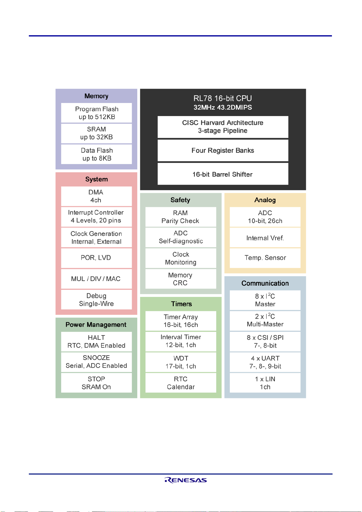
1.1 RL78/G13 Microcontroller
The RL78/G13 is 32MHz, 16-bit CPU. Figure 1 shows the block diagram of the RL78/G13.
Figure 1. RL78/G13 Block Diagram
Page 4
OB1203SD-RL-EVK Evaluation Kit Manual
X0119845 Rev.1.0
Feb 24, 2021
Page 4
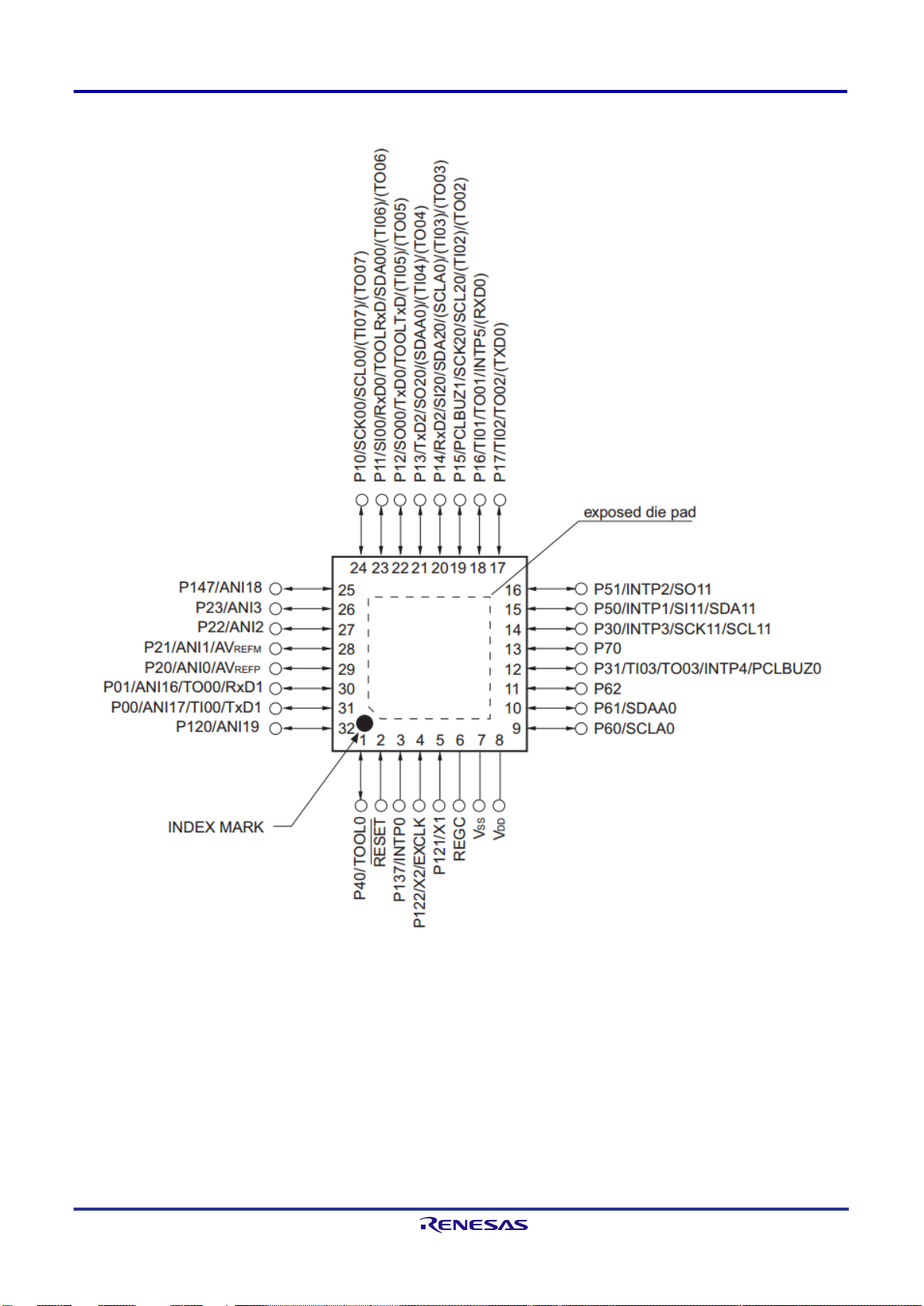
Figure 2 shows the pin configuration of the RL78/G13 (32-pin products).
Figure 2. RL78/G13 (32-pin Products) Pin Configuration
Page 5

OB1203SD-RL-EVK Evaluation Kit Manual
X0119845 Rev.1.0
Feb 24, 2021
Page 5
1.1.1. RL78/G13 Ke y Features
■
Minimum instruction execution time: Can be changed from high speed (0.03125μs: at 32MHz operation with
high-speed on-chip oscillator) to ultra-low speed (30.5μs at 32.768kHz operation with subsystem clock)
■
General-purpose registers: (8-bit register × 8) × 4 banks
■
ROM: 16KB to 512KB, RAM: 2KB to 32KB, Data Flash: 4KB to 8KB
■
Selectable high-speed on-chip oscillator clock: 32/24/16/12/8/6/4/3/2/1 MHz (Typical)
■
On-chip single power supply flash memory
■
Power management and reset function
■
On-chip power-on-reset (POR) circuit
■
On-chip voltage detector (LVD) (Select interrupt and reset from 14 levels)
■
On-chip debug function
■
On-chip key interrupt function
■
On-chip clock output/buzzer output controller
■
I/O port: 16 to 120 (N-ch open drain I/O [withstand voltage of 6 V]: 0 to 4, N-ch open drain I/O [VDD withstand
voltage EV
■
Timers
●
16-bit timer: 8 to 16 channels
●
12-bit interval timer: 1 channel
●
Real-time clock: 1 channel (calendar for 99 years, al arm function, and clock correction function)
●
Watchdog timer: 1 channel (operable with the dedicated low-speed on-chip oscillator)
■
Serial interface
■
CSI: 2 to 8 channels
■
UART/UART (LIN-bus supported): 2 to 4 channels
■
I2C/Simplified I2C communication: 2 to 8 cha nnels
■
8/10-bit resolution A/D converter: 6 to 26 channels
■
Internal reference voltage (1.45 V) and temperature sensor
■
DMA (Direct Memory Access) controller: 2/4 channels
■
Multiplier and divider/multiply-accumulator
■
16 bits × 16 bits = 32 bits (Unsigned or signed)
■
32 bits ÷ 32 bits = 32 bits (Unsigned)
■
16 bits × 16 bits + 32 bits = 32 bits (Unsigned or signed)
■
Standby function: HALT mode, STOP mode, S NOOZ E mode
■
Power supply voltage: VDD = 1.6 to 5.5V
■
Operating ambient temperature: TA = -40 to +85°C
DD withstand voltage]: 5 to 25)
Page 6
OB1203SD-RL-EVK Evaluation Kit Manual
X0119845 Rev.1.0
Feb 24, 2021
Page 6
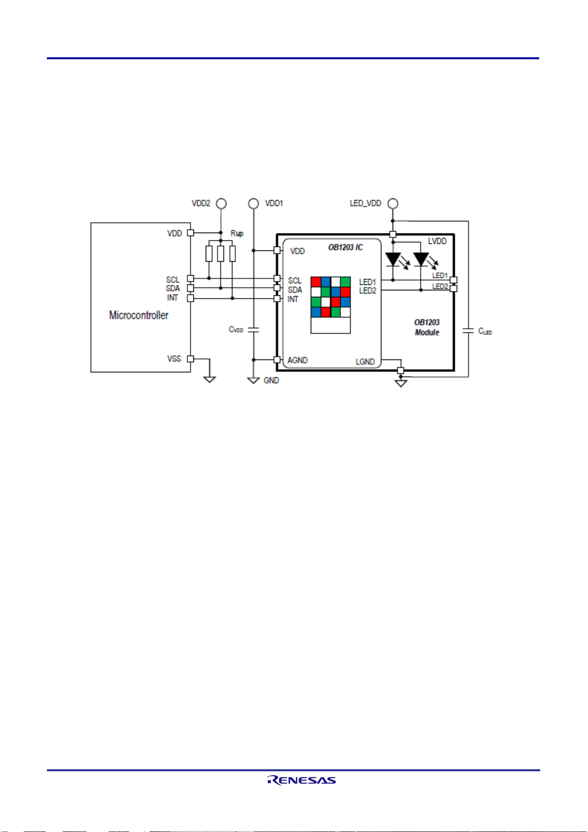
1.2 OB1203 Photoplethysmography Sensor
The OB1203 Sensor Module has a fully integrated sensor for reflective photoplethysmography (P PG), a
proximity sensor (PS), and a multi-channel light sensor (LS/CS, not used in this application). The OB1203
integrates light sources, drivers, sensors, ADC, and I2C interface in a single optically optimized package.
With the provided algorithm, human heart rate (HR), oxygen saturation (SpO
determined.
The following figure shows the typical application circuit of OB1203.
Figure 3. Typical Application Circuit
), and respiration rate are
2
1.2.1. OB1203 Key Features
1.2.1.1. Biosensor Features
■
SpO2 measurement behind visibly dark, IR transmissive ink
■
Industry’s smallest optical biosensor module
■
Fully integrated and trimmed module, including two L E Ds, 250mA maximum drive current, and photodetectors
■
Output resolution PPG: 16 to 18 bits
■
Data stored in 18-bit wide, 32-sample FIFO memory
■
Integrated averaging function for higher signal-to-noise ratio (SNR) and data rate reduction
■
Programmable measurement rate: up to 3200 samples per second
■
High SNR
1.2.1.2. Biosensor Applications
■
Sensor for Heart rate, blood oxygen saturation, and res pirat ion rate
■
Secondary sensor for blood pressure
■
Fitness and wellness, wearable devices
1.2.1.3. Physical Characteristics
■
Highly reliable and industry-proven OSIP package with integrated cover glass for hypoallergenic product s
■
Wide operation temperature: - 40 to +85°C
■
Wide supply voltage: 1.7V to 3.6V
■
Low standby current: 2μA typical
Page 7

OB1203SD-RL-EVK Evaluation Kit Manual
X0119845 Rev.1.0
Feb 24, 2021
Page 7
■
I2C interface capable of Standard Mode or Fast Mode communication; 1.8V to 3.3V logic compatibl e
■
Programmable level-based interrupt func tions with upper and lower thresholds for extending battery life
■
Industry’s smallest package: 4.2 × 2 × 1.2 mm3 14-OSIP module
1.3 ISL9111 Boost
The ISL9111 is a low input voltage and high-efficiency synchronous boost converter with a 1A switch. The
device provides a power supply solution for single-cell, dual-cell, or three-cell alkaline, NiCd or NiMH batterypowered applications. The ISL9111 has a typical 0.8V start-up voltage and can supply up to 5.25V output
voltage. It guarantees to supply 100mA from a sin gl e-cell input and 240mA from a dual-cell input when the
output is 3.3V. High 1.2MHz switching frequency al lows the use of tiny, low-profile inductors and ceramic
capacitors to minimize the size of the solution.
The following figure shows the typical application circuit of ISL9111.
Figure 4. Typical Application Circuit
1.3.1. ISL9111 K ey Features
■
Up to 97% Efficiency at Typical Operating Conditions
■
Minimum Start-up Voltage
●
0.8V (ISL9111)
●
0.6V (ISL9111A)
■
Minimum Operating Voltage
●
0.7V (ISL9111)
●
0.5V (ISL9111A)
■
Low Quiescent Current: 20μA (Typical)
■
At VOUT = 3.3V
●
100mA Output Current at VIN = 0.9V
●
240mA Output Current at VIN = 1.8V
■
Logic Control Shutdown (Iq < 1µA)
■
Output Voltage up to 5.25V
■
Output Disconnect during Shutdown
■
Skip Mode under Light Load Condition
■
Undervoltage Lockout (ISL9111 Only)
■
Fault Protection: OVP (ADJ Version Only), OTP, Short Circuit
■
6 Ld SOT-23 Package
Page 8

OB1203SD-RL-EVK Evaluation Kit Manual
X0119845 Rev.1.0
Feb 24, 2021
Page 8
1.4 Setup and Configuration
The evaluation kit runs on battery power. After switching the battery switch ON, press the power key S1 to start
the SpO
and HR measurements.
2
Without target (for example, a finger) or without av ai l able SpO
or HR data, the OLED displays lines as shown in
2
Figure 5.
Figure 5. No Measurement
Place your finger on the sensor as shown in Figure 3.3. Keep the pressure on the sensor low to avoid blood flow
restriction. With the finger on the sensor, t he IR LED and red LED light up and the measurement starts. After a
few seconds, the SpO
and heart rate are displayed (see Figure 6).
2
Figure 6. Measurement
Page 9

OB1203SD-RL-EVK Evaluation Kit Manual
X0119845 Rev.1.0
Feb 24, 2021
Page 9
2. Board Design
The OB1203 sensor interrupt triggers the MCU to read the sensor data.
The MCU determines blood oxygen saturation, he art and respiration rate, and sends the data v i a I2C to the
OLED display. The OLED displays the data along with the battery status.
The ISL9111 adjusts the voltage of two AAA batteries to the systems supply needs of 3.3V.
The S1 button powers on the system.
The following figures show the board’s pictures.
Figure 7. OB1203SD-RL-EVK (Bottom)
Figure 8. OB1203SD-RL-EVK (Top)
Page 10

OB1203SD-RL-EVK Evaluation Kit Manual
X0119845 Rev.1.0
Feb 24, 2021
Page 10
Component
Type
Remark
Photoplethysmography
OB1203
Renesas part: Heart Rate, Blood Oxygen Concentration, Pulse Oximetry,
OLED
SSD1306
Available from local suppliers
Battery
AAA battery
Available from local suppliers
Boost IC (3.3V)
ISL9111
Renesas part
MCU
RL78/G13
Renesas part (R5F100BGA)
2.1 System Outline
The OB1203 (bio-sensor module) integrates a red and IR LED, LED drivers, photodetectors, ADC and I2C
module. In PPG mode, it measures the amount of ref l ect ed l i ght of the red and infrared LEDs from a target
object like a finger. The photodiodes output signal s are converted to digital values by the integrated ADC and
stored in a FIFO buffer readable via I2C bus.
The MCU calculates oxygen saturation, pulse and respiration rate with the provided algorithm. Oxygen
saturation, pulse and respiration rate are displayed on an OLED panel.
The ISL9111 is a low input voltage and high efficiency synchronous boost converter with 1A switch.
The following figure shows the system block diagram.
Figure 9. System Block Diagram
2.1.1. Main Component s
The following table lists the main components of the evaluation kit.
Table 1. Main Components of the Evaluation Kit
sensor module
Proximity, Light and Color Sensor
Page 11

OB1203SD-RL-EVK Evaluation Kit Manual
X0119845 Rev.1.0
Feb 24, 2021
Page 11
No.
Pin Name
Connection
Function Description
Function Module
1
P31
INTB
Interrupt from HR, SpO2 and RR
I2C communication with HR, SpO2 and
2
P61
SDAA0
IIC data for OB1203
3
P60
SCLA0
IIC clock for OB1203
4
P30
SCL11
IIC clock for OLED module
OLED (SSD1306) control
5
P50
SDA11
IIC data for OLED module
6
P22
ANI2
A/D input
Battery level detection
7
P51
IRQ2
Interrupt input
System power up
8
P70
POWER_ON
I/O for power enable
2.1.2. MCU Pins Used
The following table lists the used pins and their functions.
Table 2. Pins used
sensor (OB1203)
2.2 Power Supply
The system’s power supply includes the following parts:
■
3.3V boost Circuit
■
Power ON Control
■
2 AAA batteries
RR sensor (OB1203)
2.2.1. 3.3V Boost Circuit
The following figure shows the schematic of t he boost circuit.
Figure 10. Boost Circuit
The power supply (2 AAA battery) acts as the input (VIN) for the ISL9111 to generate 3.3V system power. The
ISL9111 provides a power supply solution for singl e-cell, dual- or three-cell alkaline, NiCd or NiMH batterypowered applications, capable of sourcing up t o 1A output current. This boost converter operat es f rom i nput
voltage of 0.7V to 6.5V. The output voltage of the ISL9111 can be programmed from 2.5V to 5.25V.
Page 12

OB1203SD-RL-EVK Evaluation Kit Manual
X0119845 Rev.1.0
Feb 24, 2021
Page 12
2.2.2. Power ON Control
The following figure shows the schematic of power ON control circuit.
Figure 11. Power ON Control Circuit
When pressing the S1 button, the system is conne ct ed to BAT+ through D6, Q5, and the MOSFET Q3. After the
MCU’s Power-on Reset, the MCU checks on the battery voltage:
■
Battery voltage is nominal – The MCU sets the Power_On line high keeping the system powered when S1 i s
released.
■
Battery voltage is low – Power_On is not set high. The MCU is powered off when S1 is released.
Page 13

OB1203SD-RL-EVK Evaluation Kit Manual
X0119845 Rev.1.0
Feb 24, 2021
Page 13
SCL1
BS2
12
BS0
10
BS1
11
IR EF
26
CS#
13
D/C#
15
RES#
14
D1
19
D0
18
D2
20
C2P
2
C2N
3
C1P
4
C1N
5
VCOMH
27
VCC
28
VLSS
29
VSS
8
VBAT
6
VDD
9
D3
21
D4
22
D5
23
D6
24
D7
25
R/W#
16
E/RD#
17
NC_3
30
NC_2
7
NC_1
1
U2
SSD1306
910K
R5
1uF
C3
1uF
C4
4.7uFC52.2uF
C6
1uFC11uF
C2
4K7
R10
1N4148
D1
10uF
C9
3.3V
3.3V 3.3V
3.3V
SDA1
4K7
R11
4K7
R12
10KR610K
R7
GND
GND
GND
GND
2.3 OLED Circuit
The following figure shows the schematic of OLED circuit.
OLED display uses SSD1306 as the main control IC. T he RL78/G13 communicates with the SSD1306 through
I2C in order to control the OLED display.
2.4 OB1203 Circuit
The following figure shows the schematic for the OB1203 circuit.
Figure 12. OLED Circuit
Figure 13. OB1203 Circuit
Page 14

OB1203SD-RL-EVK Evaluation Kit Manual
X0119845 Rev.1.0
Feb 24, 2021
Page 14
Item
Description
Microcontroller used
RL78/G13 (R5F100BG,128KB ROM,12KB RAM)
Operating frequency
High-speed on-chip oscillator (HOCO) clock: 32MHz
Operating voltage
3.3V
Integrated development
e2 studio V7.6.0 from Renesas Electronics Corp
main()
Call OB1203 main process
ob1203_spo2_main()
While(1)
Peripheral initialization
R_MAIN_UserInit()
R_MAIN_UserInit
Enable interrupt
EI()
Start INTC4 operation
for OB1203 interrupt input
RET
3. Software
3.1 Integrated Development Environment
The provided code has been developed to run under the conditions listed in the table below.
Table 5.1 Operation Conditions
CPU/peripheral hardware clock: 32MHz
(RL78/G13 at 24MHz: 1.6V - 5.5V; OB1203: 1.7V - 3.6V,
IR LED and red LED: 3.3V - 4.5V)
environment (e2 studio)
3.2 Main Process
Figure 14 and Figure 15 show the flowchart for the ‘main()’ routine and the user initialization routine
‘R_MAIN_UserInit()’.
Figure 14. Main Processing Routine
Figure 15. User Initialization Routine
Page 15

OB1203SD-RL-EVK Evaluation Kit Manual
X0119845 Rev.1.0
Feb 24, 2021
Page 15
Set the defau lt configuration
to OB1203 via I2C0
defaultConfig()
Set OB1203 INT vector to
proximity Event
Start timer for 10ms counter
t_start()
Get the sum of squares
spo2.get_sum_squares()
ob1203_spo2_main()
Proximity mode?
Generated
proximity INT?
Counter > 0.5s?
FIFO full INT:
afull_int_en = 1?
Bio-sensor mode
Y
N
Y
N
Y
N
Make algorithm part1
spo2.do_algorithm_part1()
samples_processed = 0
(clear flag)
do_part2 = 1 (set flag)
Y
N
Counter < 1s?
Bio-sensor mode?
samples_ready = 1?
Get sensor data, and adjust
LED current gain for the fit
sensor count v alue
get_sensor_data()
samples_processed = 1 (set flag)
do_pa rt2 && afull_int_en
&&samples_pro cessed ?
Make algorithm part2
spo2.do_algorithm_part2()
Update resul t display
OLED_display_update()
Clear do_part2,
samples_processed flag
Y
Y
Y
Y
N
N
N
N
When OB1203 LED1 &
LED2 current adjust is
completed, and specified
amount of IR data and red
data are in range,
afull_int_en bit is set to 1.
Reset timer
t_reset()
OLED display sensor off status
OLED_Sensor_Off()
Increment idle_counter
idle_counter > 60s?
Clear idle_counter, and call
power off subroutine
Power_Off_Ctrl()
Y
While(1)
Initialize parameters for
OB1203 and spo2
ob1203.OB1203_init()
spo2.SPO2_init()
OLED display sensor off status
OLED_Sensor_Off()
Battery and u nit display
Battery_Display_InApp()
N
Set “Power On" pin to High
Power_On_Ctrl()
Initialize and clear OLED
OLED_Init()
OLED_Clear()
Delay 2s for key long press
Reset timer
t_reset()
Get proximity data, and judge
to switch to bio-sensor mode
Get_prox_data()
3.3 OB1203 Module Routines
The following figure shows the flowchart of oximeter measure routine.
Figure 16. PPG Measurement Routine
Page 16

OB1203SD-RL-EVK Evaluation Kit Manual
X0119845 Rev.1.0
Feb 24, 2021
Page 16
Part Number
Description
OB1203SD-RL-EVK
OB1203SD-RL-EVK Evaluation Kit
Revision
Date
Description
1.0
Feb 24, 2021
Initial release.
4. Related Information
■
RL78/G13 Microcontroller User's Manual: Hard ware
■
OB1203 Datasheet
■
ISL9111 Datasheet
5. Ordering Information
6. Revision History
Page 17

IMPORTANT NOTICE AND DISCLAIMER
RENESAS ELECTRONICS CORPORATION AND ITS SUBSIDIARIES (“RENESAS”) PROVIDES TECHNICAL
SPECIFICATIONS AND RELIABILITY DATA (INCLUDING DATASHEETS), DESIGN RESOURCES (INCLUDING
REFERENCE DESIGNS), APPLICATION OR OTHER DESIGN ADVICE, WEB TOOLS, SAFETY INFORMATION, AND
OTHER RESOURCES “AS IS” AND WITH ALL FAULTS, AND DISCL AIMS ALL WARRANTIES, EXPRESS OR IMPLIED,
INCLUDING, WITHOUT LIMITATION, ANY IMPLIED WARRANTIES OF MERCHANTABILITY, FITNESS FOR A
PARTICULAR PURPOSE, OR NON-INFRINGEMENT OF THIRD PARTY INTELLECTUAL PROPERTY RIGHTS.
These resources are intended for developers skilled in the art designing with Renesas products. You are solely responsible
for (1) selecting the appropriate products for your application, (2) designing, validating, and testing your application, and (3)
ensuring your application meets applicable standards, and any other safety, security, or other requirements. These
resources are subject to change without notice. Renesas grants you permission to use these resources only for
development of an application that uses Renesas products. Other reproduction or use of these resources is strictly
prohibited. No lic ense is granted to any other Renesas intellectual property or to any third party intellectual property.
Renesas disclaims responsibility for, and you will fully indemnify Renesas and its representatives against, any claims,
damages, costs, losses, or liabilities arising out of your use of these resources. Renesas' products are provided only subject
to Renesas' Terms and Conditions of Sale or other applicable terms agreed to in writing. No use of any Renesas resources
expands or otherwise alters any applicable warranties or warranty disclaimers for these products.
Corporate Headquarters
TOYOSU FORESIA, 3-2-24 Toyosu,
Koto-ku, Tokyo 135-0061, Japan
www.renesas .com
Trademarks
Renesas and the Renesas logo are trademarks of Renesas
Electronics Corporation. All trad emarks and registered
trademarks are the property of their respective owners.
(Rev.1.0 Mar 2020)
Contact Information
For further information on a product, technology, the most
up-to-date version of a document, or your nearest sales
office, please visit:
www.renesas .com/contact/
© 2021 Renesas Electronics Corporation. All rights reserved.
 Loading...