

Page 1

Application Note
Renesas Synergy™ Platform
NetX™ and NetX Duo™ Auto IP Module Guide
Introduction
This module guide will enable you to effectively use a module with your own design. Upon completion of this
guide, you will be able to add this module to your own design, configure it correctly for the target application,
and write code using the included application project code as a reference and efficient starting point.
References to more detailed API descriptions and suggestions of other application projects that illustrate
advanced uses of the module are available on the Renesas Syner g y Knowledg e Bas e (see the References
section at end of the document), it is a valuable resources for creating more complex designs.
The Auto IP Protocol is design ed to dynamically configure IPv4 addresses on a local network without
requiring a server; unlike the Dynamic Host Configuration Protocol (DHCP). Auto IP uses address resolution
protocol (ARP) for automatic IP address assignment and allocates addresses in the range of 169.254.1.0
through 169.254.254.255.
™
Note: Except for internal processing, the NetX Duo
running of an Auto IP session as the NetX
Contents
1. NetX and NetX Duo Auto IP Module Features ......................................................................... 2
Auto IP is identical in the application, set-up, and
™
Auto IP.
2. NetX and NetX Duo Auto IP Module APIs Overview ................................................................ 2
3. NetX and NetX Duo Auto IP Module Operational Overview ..................................................... 3
3.1 NetX and NetX Duo Auto IP Module Important Operational Notes and Limitations ............................... 4
3.1.1 NetX and NetX Duo Auto IP Module Operational Notes ....................................................................... 4
3.1.2 NetX and NetX Duo Auto IP Module Limitations ................................................................................... 4
4. Including the NetX and NetX Duo Auto IP Module in an Application ........................................ 4
5. Configuring the NetX and NetX Duo Auto IP Module ............................................................... 5
5.1 Configuration Settings for the NetX and NetX Duo Auto IP Lower-Level Modules ................................. 6
5.2 NetX and NetX Duo Auto IP Module Clock Configuration ...................................................................... 8
5.3 NetX and NetX Duo Auto IP Module Pin Configuration .......................................................................... 8
6. Using the NetX and NetX Duo Auto IP Module in an Application ............................................. 8
7. The NetX and NetX Duo Auto IP Module Application Project ................................................... 9
8. Customizing the NetX and NetX Duo Auto IP Module for a Target Application ...................... 13
9. Running the NetX and NetX Duo Auto IP Module Application Project .................................... 13
10. NetX and NetX Duo Auto IP Module Conclusion .................................................................... 15
11. NetX and NetX Duo Auto IP Module Next Steps .................................................................... 15
12. NetX and NetX Duo Auto IP Module Reference Information .................................................. 16
Revision History ............................................................................................................................ 18
R11AN0135EU0102 Rev.1.02 Page 1 of 18
May.02.19
Page 2
Renesas Synergy™ Platform NetX™ and NetX Duo™ Auto IP Module Guide
Function Name
Example API Call and Description
nx_auto_ip_create
nx_auto_ip_create(&g_auto_ip0, "AutoIP 0", &g_ip0,
Create an Auto IP instance
1. NetX and NetX Duo Auto IP Module Features
• Compliant with RFC3927 and related RFCs
• Uses ARP probes to check for address conflicts
• Uses the collision handler notification in NetX to detect an address already in use
• Registers a valid Auto IP address with the IP instance
• Provides high-level APIs for:
Creating and deleting an Auto IP instance
Starting and stopping the Auto IP thread task
Specifying the network interface on which to run Auto IP
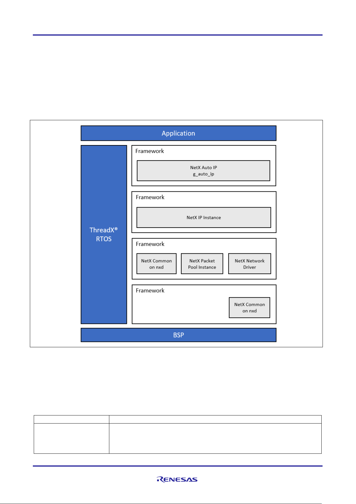
Figure 1. NetX and NetX Duo Auto IP Module Block Diagram
2. NetX and NetX Duo Auto IP Module APIs Overview
The NetX Auto IP def ines APIs for creating, deleting, getting, and s etting addresses. A c omplete list of the
available APIs, an example API call, and a short description of each can be found in the following table. A table
of status return values follows the API summary table.
Table 1. NetX and NetX Duo Auto IP Module API Summary
stack_pointer, stack_size, priority);
R11AN0135EU0102 Rev.1.02 Page 2 of 18
May.02.19
Page 3

Renesas Synergy™ Platform NetX™ and NetX Duo™ Auto IP Module Guide
Function Name
Example API Call and Description
nx_auto_ip_delete
nx_auto_ip_delete(&g_auto_ip_0);
Delete Auto IP instance.
nx_auto_ip_get_address
nx_auto_ip_get_address(&g_auto_ip_0, &local_address);
Get current Auto IP address.
nx_auto_ip_set_interface
nx_auto_ip_set_interface(&g_auto_ip_0, interface_index);
Set network interface needing an Auto IP address.
nx_auto_ip_start
nx_auto_ip_start(&g_auto_ip_0, IP_ADDRESS(0,0,0,0));
nx_auto_ip_stop
nx_auto_ip_stop(&g_auto_ip_0);
Stop Auto IP processing.
nx_dhcp_server_stop
nx_dhcp_server_stop(&dhcp_server);
Name
Description
NX_SUCCESS
Successful AutoIP function
NX_AUTO_IP_ERROR
Error creating components of Auto IP instance
NX_PTR_ERROR*
Invalid pointer input
NX_CALLER_ERROR*
Invalid caller of this service
NX_AUTO_IP_NO_LOCAL
No Auto IP address registered with the NetX IP instance.
NX_AUTO_IP_BAD_INTERFACE_INDEX
Invalid network interface
Start Auto IP processing. If the address input is NULL. NetX Auto IP randomly
assigns an address in the Auto IP address range.
Stop DHCP server processing.
Note: For details on operation and definitions for the function data structures, typedefs, defines, API data,
API structures, and function variables, review the associated Express Logic User’s Manual in the
References section.
Table 2. Status Return Values
Note: Lower-level drivers may return common error codes. Refer to the SSP User’s Manual API References
for the associated module for a definition of all relevant status return values.
* These are error codes which are only returned if error checking is enabled. Refer to the NetX User
Guide for the Renesas Synergy™ Platform or NetX Duo User’s Guide for the Renesas Synergy™
Platform for more details on error-checking services in NetX and NetX Duo, respectively.
3. NetX and NetX Duo Auto IP Module Operational Overview
The NetX Auto IP protocol first selects a random address within the Auto IP IPv4 address range of
169.254.1.0 through 169.254.254.255. Alternatively, the application may force a starting IP address by
providing it to the nx_auto_ip_start service; this is useful in situations where an Auto IP address has
been used previously.
Once an auto IP address is selected, the NetX Auto IP sends out a series of ARP probes for the selected
address. An ARP probe consists of an ARP request message with the sender address set to 0.0.0.0 and the
target address set to the desired Auto IP address. A series of these ARP probes are sent (the actual number
is set by the ARP probes to send property of the NetX Auto IP instance); if another network node responds
to this probe or sends an identical probe for the same address, a new auto IP address is randomly selected
within the auto IP IPv4 address range and the probe processing repeats.
If ARP probes to send and probes are sent without any responses, the NetX Auto IP issues many ARP
announcements (set by the Number of ARP announces property) for the selected address. An ARP
announcement consists of an ARP request message with both the sender and target address in the ARP
message set to the selected auto IP address. If another network node responds to an announced message
or sends an identical announcement for the same address, a new auto IP address is randomly selected
R11AN0135EU0102 Rev.1.02 Page 3 of 18
May.02.19
Page 4

Renesas Synergy™ Platform NetX™ and NetX Duo™ Auto IP Module Guide
Resource
ISDE Tab
Stacks Selection Sequence
g_auto_ip0 NetX Auto IP
Threads
New Stack> X-Ware> NetX> Protocols> NetX Auto IP
g_auto_ip0 NetX Duo Auto IP
Threads
New Stack> X-Ware> NetX Duo> Protocols> NetX Duo
Auto IP
within the auto IP IPv4 addr es s range, and the probe processing starts over. When the probe, and the
announcement, com pletes with out any detected conflicts, the selected auto IP address is considered valid
and the address is registered with the IP inst a nce.
The NetX Auto IP registers the auto IP-generated IP address with the NetX IP instance successful probe and
announcement processing. The Auto IP application can be notified of address changes using the
nx_ip_address_change_notify callback in NetX, or it can use the nx_ip_status_check to
determine when a valid IP address is assigned. Once a valid address is assigned, the application should
stop the auto IP task using the nx_auto_ip_stop service. The address change callback notifies the
application of address changes after the auto IP thread task is suspended. Possible reasons for an address
changing without explicitly being done with an auto IP may be due to auto IP-address conflicts with other
nodes, or a DHCP address resolution to replace the auto IP address.
3.1 NetX and NetX Duo Auto IP Module Important Operational Notes and Limitations
3.1.1 NetX and NetX Duo Auto IP Module Operational Notes
• The NetX DHCP Client and NetX Auto IP can both be used to ensure a host has a valid IP address.
Typically, the DHCP Client attempts to contact a server. If none of the servers respond to the DHCP
Client, the client is suspended, and the auto IP task is started. Auto IP generally guarantees a local
address even if no DHCP Server is available. The DHCP Client can try later to broadcast requests to a
DHCP Server; this process, if successful, automatically overwrites the auto IP local address.
• When the IP address changes, the application is responsible for closing out existing socket connections.
3.1.2 NetX and NetX Duo Auto IP Module Limitations
• If the NetX DHCP is used with the auto IP, the DHCP thread created must have a higher priority than the
auto IP thread.
• The NetX Auto IP does not provide a mechanism to retain previously used IP address.
Refer to the latest SSP Release Notes for any additional operational limitations for this module.
4. Including the NetX and NetX Duo Auto IP Module in an Application
This section describes how to include either or both NetX and NetX Duo Auto IP module in an application
using the SSP configurator.
Note: It is assumed you are familiar with creating a project, adding threads, adding a stack to a thread, and
configuring a block within the stack. If you are unfamiliar with any of these items, refer to the first few
chapters of the SSP Us er ’s Manual to learn how to manage each of these important steps in creating
To add the NetX and NetX Duo Auto IP module to an application, simply add it to a thread using the stacks
selection sequence given in the following table. (The default name for the NetX and NetX Duo Auto IP
module is g_auto_ip0. This name can be changed in the associated Properties window.)
Table 3. NetX and NetX Duo Auto IP Module Selection Sequence
As shown in the following figure, when the NetX Auto IP module is added to the thread stack, the
configurator automatically adds any needed lower-level modules. Any modules needing additional
configuration inform ation have the box text highlighted in Red. Modul es with a Gray band are individual
modules that stand alone. Modules with a Blue band are shared or common; they need only be added once
and can be used by multiple stacks. Modules with a Pink band can require the selection of lower-level
modules; these are either optional or recommended. (This is indicated in the block with the inclusion of this
text.) If the addition of lower-level modules is required, the module description include Add in the text.
SSP-based applications.
R11AN0135EU0102 Rev.1.02 Page 4 of 18
May.02.19
Page 5
Renesas Synergy™ Platform NetX™ and NetX Duo™ Auto IP Module Guide
Parameter
Value
Description
Wait before sending first probe
(seconds)
1
Wait before sending first probe selection
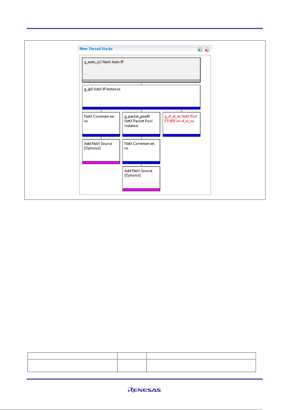
Clicking on any Pink banded modules brings up the New icon and displays possible choices.
Figure 2. NetX and NetX Duo Auto IP Module Stack
5. Configuring the NetX and Ne tX Duo Auto IP Module
The NetX Auto IP module must be configured by the user for the desired operation. The SSP configuration
window automatically identifies (by highlighting the block in red) any required configuration selections, such
as interrupts or operating modes, which must be configured for lower-level modules for successful operation.
Only properties that can be changed without causing conflicts are available for modification. Other properties
are locked and not available for changes and are identified with a lock icon for the locked property in the
Properties window in the ISDE. This approach simplifies the configuration process and makes it much less
error-prone than previous manual approaches to configuration. The available configuration settings and
defaults for all the user-accessible properties are given in the Properties tab within the SSP Configurator
and are shown in the following tables for easy reference.
One of the properties most often identified as requiring a change is the interrupt priority; this configuration
setting is available within the Properties window of the associated module. Simply select the indicated
module and then view the Properties window; the interrupt settings are often toward the bottom of the
properties list, so scroll down until they become available. Also note that the interrupt priorities listed in the
Properties win do w in the ISDE indicates the validity of the setting based on the targeted MCU (CM4 or
CM0+). This level of detail is not included in the following configuration properties tables but is easily visible
with the ISDE when configuring interru pt -priority levels.
Note: You may want to open your ISDE, create the module, and explore the property settings in parallel
with looking over the following configuration table values. This helps to orient you and can be a useful
Table 4. Configuration Settings for the NetX and NetX Duo Auto IP Module
hands-on approach to learning the ins and outs of developing with SSP.
R11AN0135EU0102 Rev.1.02 Page 5 of 18
May.02.19
Page 6

Renesas Synergy™ Platform NetX™ and NetX Duo™ Auto IP Module Guide
Parameter
Value
Description
ARP probes to send
3
ARP probes to send selection
Minimum wait between probes
1
Minimum wait between probes selection. (The
probes.)
Maximum wait between probes
(seconds)
2
Maximum wait between probes selection
Maximum conflicts before increasing
10
Maximum conflicts before increasing processing
address.
Wait extend after maximum conflicts
60
Interval that Auto IP waits before trying another
reached.
Wait before announcement (seconds)
2
Wait before announcement if the local IP
address being probed results in zero conflicts.
Number of ARP announces
2
Number of ARP announcements sent selection
Wait between announces (seconds)
2
Wait between announces selection
Wait between defense announces
(seconds)
10
Wait between defense announces selection
Name
g_auto_ip0
Module name
Internal thread stack size (bytes)
2048
Internal thread stack size selection
Internal thread priority
3
Internal thread priority selection
ISDE Property
Value
Description
Name
g_ip0
Module name
IPv4 Address (use commas for
separation)
0,0,0,0
IPv4 Address selection
Subnet Mask (use commas for
separation)
255,255,255,0
Subnet Mask selection
**IPv6 Global Address (use commas
for separation)
0x2001, 0x0, 0x0, 0x0,
0x0, 0x0, 0x0, 0x1
IPv6 global address selection
**IPv6 Link Local Address (use
zeros use the MAC address)
0x0, 0x0, 0x0, 0x0, 0x0,
IPv6 link local address selection
IP Helper Thread Stack Size (bytes)
2048
IP Helper Thread Stack Size (bytes)
selection
IP Helper Thread Priority
3
IP Helper Thread Priority selection
ARP
Enable
ARP selection
ARP Cache Size in Bytes
520
ARP Cache Size in Bytes selection
(seconds)
processing delay
(seconds)
Note: The example settings and defaults are for a project using the S7G2 Synergy MCU Group. Other
MCUs may have different default values and available configuration settings.
In some cases, settings other than the defaults for stack modules can be desirable. For example, it might be
useful to select different addresses for the Ethernet port. The configurable properties for the lower-level stack
modules are given in the following sections for completeness and as a reference.
Auto IP recommends a random delay between
delay before Auto IP tries another local IP
local address after the maximum conflicts is
Note: Most of the property settings for lower-level modules are intuitive and usually can be determined by
inspection of the associated properties window from the SSP configurator.
5.1 Configuration Settings for the NetX and NetX Duo Auto IP Lower-Level Modules
Only a small number of settings must be modified from the default for the IP layer and lower-level drivers as
indicated via the red text in the thread stack block. Notice that some of the configuration properties must be
set to a certain value for proper framework operation and are locked to prevent user modification. The
following table identifies al l th e settings within the properties section for the module.
Table 5. Configuration Settings for the NetX and NetX Duo IP Instance
commas for separation. When All
0x0, 0x0, 0x0
R11AN0135EU0102 Rev.1.02 Page 6 of 18
May.02.19
Page 7

Renesas Synergy™ Platform NetX™ and NetX Duo™ Auto IP Module Guide
ISDE Property
Value
Description
Reverse ARP
Enable, Disable
Default: Disable
Reverse ARP selection
TCP
Enable, Disable
TCP selection
UDP
Enable
UDP selection
ICMP
Enable, Disable
ICMP selection
IGMP
Enable, Disable
Default: Enable
IGMP selection
IP fragmentation
Enable, Disable
IP fragmentation selection
ISDE Property
Value
Description
No configurable parameters
ISDE Property
Value
Description
Name
g_packet_pool0
Module name
Packet Size in Bytes
640
Packet size selection
Number of Packets in Pool
16
Number of packets in pool selection
ISDE Property
Value
Description
Parameter Checking
BSP, Enabled, Disabled
Enable or disable the parameter
Channel 0 Phy Reset Pin
IOPORT_PORT_09_PIN_03
Channel 0 Phy reset pin selection
Channel 0 MAC Address
0x00002E09
Channel 0 MAC address high bits
Channel 0 MAC Address
Low Bits
0x0A0076C7
Channel 0 MAC address low bits
selection
Channel 1 Phy Reset Pin
IOPORT_PORT_07_PIN_06
Channel 1 Phy reset pin selection
Channel 1 MAC Address
High Bits
0x00002E09
Channel 1 MAC address high bits
selection
Channel 1 MAC Address
0x0A0076C8
Channel 1 MAC address low bits
Number of Receive Buffer
Descriptors
8
Number of receive buffer descriptors
selection
Number of Transmit Buffer
32
Number of transmit buffer descriptors
Ethernet Interrupt Priority
Priority 0 (highest), Priority 1:2,
(CM4 lowest - not valid if using
Ethernet interrupt priority selection
Default: Enable
Default: Enable
Default: Disable
Note: The example settings and defaults are for a project using the Synergy S7G2 MCU Group. Other
MCUs may have different default values and available configuration settings.
Table 6. Configuration Settings for the NetX and NetX D uo Common Instance
Note: The example settings and defaults are for a project using the S7G2 Synergy MCU Group. Other
Table 7. Configuration Settings for the NetX and NetX Duo Packet Pool Instance
** Indicates properties that are only available in NetX Duo.
MCUs may have different default values and available configuration settings.
Note: The example settings and defaults are for a project using the S7G2 Synergy MCU Group. Other
MCUs may have different default values and available configuration settings.
Table 8. Configuration Settings for the NetX Port ETHER
Default: BSP
High Bits
Low Bits
Descriptors
checking
selection
selection
selection
Priority 3 (CM4: valid, CM0+:
lowest- not valid if using
®
ThreadX
), Priority 4:14 (CM4:
valid, CM0+: invalid), Priority 15
R11AN0135EU0102 Rev.1.02 Page 7 of 18
May.02.19
Page 8

Renesas Synergy™ Platform NetX™ and NetX Duo™ Auto IP Module Guide
ISDE Property
Value
Description
ThreadX, CM0+: invalid)
Default: Disabled
Name
g_sf_el_nx
Module name
Channel
0
Channel selection
Callback
NULL
Callback selection
Resource
ISDE Tab
Pin selection Sequence
ETHERC
Pins
Select Peripherals > Connectivity:ETHERC > ETHERC1.RMII
Property
Value
Description
Operation Mode
Disabled, Custom, RMII
(Default: Disabled)
Select RMII as the Operation Mode for ETHERC1
Pin Group Selection
Mixed, _A only
Pin group selection
REF50CK
P701
REF50CK Pin
TXD0
P700
TXD0 Pin
TXD1
P406
TXD1 Pin
TXD_EN
P405
TXD_EN Pin
RXD0
P702
RXD0 Pin
RXD1
P703
RXD1 Pin
RX_ER
P704
RX_ER Pin
CRS_DV
P705
CRS_DV Pin
MDC
P403
MDC Pin
MDIO
P404
MDIO Pin
Note: The example settings and defaults are for a project using the S7G2 Synergy MCU Group. Other
MCUs may have different default values and available configuration settings.
5.2 NetX and NetX Duo Auto IP Module Clock Configuration
The ETHERC peripheral module uses PCLKA as its clock source. The PCLKA frequency is set using the
SSP configurator clock tab prior to a build, or by using the CGC interface at run-time.
5.3 NetX and NetX Duo Auto IP Module Pin Configuration
The ETHERC peripheral module uses pins on the MCU device to communicate to external devices. I/O pins
must be selected and configured by the external device as required. The following table illustrates the
method for selecting the pins within the SSP configuration window and the subsequent table illustrates an
example selection for the I
Note: The selected operation mode determines the peripheral signals available and the MCU pins required.
Table 9. Pin Selection for the ETHERC Module
2
C pins.
Note: The selection sequence assumes ETHERC1 is the desired hardware target for the driver.
Table 10. Pin Configuration Settings for the ETHERC1
(Default: _A only)
Note: Example settings are for a project using the S7G2 Synergy MCU and the SK-S7G2 Kit. Other Synergy
MCUs and other Synergy Kits may have different available pin configuration settings.
6. Using the NetX and NetX Duo Auto IP Module in an Application
In a typical application, it is assumed that an IP instance has been created and an ARP is enabled. Once this
IP instance is accomplished, the typical steps in using the NetX Auto IP in an application are:
1. Allow time for the IP thread task and the network driver to get initialized (2-3 seconds) using the
tx_thread_sleep() API
2. Set the address change notification with the nx_ip_address_change_notify API [Optional]
3. Start the Auto IP instance with the nx_auto_ip_start API.
R11AN0135EU0102 Rev.1.02 Page 8 of 18
May.02.19
Page 9

Renesas Synergy™ Platform NetX™ and NetX Duo™ Auto IP Module Guide
Resource
Revision
Description
e2 studio
7.3.0 or later
Integrated Solution Development Environment
4. Check for a valid address for the IP instance using either the nx_ip_status_check or
nx_auto_ip_get_address API.
The nx_ip_status_check API defaults to the primary address. If running Auto IP on a secondary
interface, use the nx_ip_interface_status_check. Note that nx_auto_ip_get_address API works
for Auto IP on either primary or secondary addresses.
5. If a valid local IP address is assigned, stop the auto IP thread task using the nx_auto_ip_stop API.
The following figure illustrates common steps in a typical operational flow diagram:
Figure 3. Flow Diagram of a Typical NetX and NetX Duo A u to IP Module Application
7. The NetX and NetX Duo Auto IP Module Application Project
The application project associated with this module guide demonstrates the steps needed in a full design.
The project can be found using the link provided in the References section at the end of this document. You
may want to import and open the application project within the ISDE and view the configuration settings for
the NetX and NetX Duo Auto IP module. You can also read over the code in autoip_thread_entry.c
which illustrates the NetX and NetX Duo Auto IP module APIs in a complete design.
The application project demonstrates the typical use of the NetX and NetX Duo Auto IP module APIs. The
auto IP protocol is responsible for selecting a valid IP address; this is a helpful method in non-DHCP cases,
for example. Appropriate NetX functions are used to monitor the network connection.
The following table identifies the target versions for the associated software and hardware used by the
Application Project:
Table 11. Software and Hardware Resources Used by the Application Project
R11AN0135EU0102 Rev.1.02 Page 9 of 18
May.02.19
Page 10

Renesas Synergy™ Platform NetX™ and NetX Duo™ Auto IP Module Guide
Resource
Revision
Description
SSP
1.6.0 or later
Synergy Software Platform
IAR EW for Synergy
8.23.3 or later
IAR Embedded Workbench® for Renesas Synergy™
SSC
7.3.0 or later
Synergy Standalone Configurator
SK-S7G2
v3.0 to v3.3
Starter Kit
A simple flow diagram of the application project is given in the figure below:
Figure 4. NetX and NetX Duo Auto IP Module Application Pro ject Flow Diagram
The autoip_thread_entry.c file is located in the project once it has been imported into the ISDE. You
can open this file within the ISDE and follow along with the description provided to help identify key uses of
APIs.
The first section of the autoip_thread_entry.c has the header files which reference the NetX and NetX
Duo Auto IP instance and integer types. The next section contains macro definitions, that created to improve
code readability and included for your convenience. Next, a variable is defined; it hol ds the number of IP
address changes.
R11AN0135EU0102 Rev.1.02 Page 10 of 18
May.02.19
Page 11

Renesas Synergy™ Platform NetX™ and NetX Duo™ Auto IP Module Guide
ISDE Property
Value Set
Wait before sending first probe (seconds)
1
ARP probes to send
3
Minimum wait between probes (seconds)
1
Maximum wait between probes (seconds)
2
Maximum conflicts before increasing processing
delay
10
Wait extend after maximum conflicts (seconds)
60
Wait before announcement (seconds)
2
Number of ARP announces
2
Wait between announces (seconds)
2
Wait between defense announces (seconds)
10
Name
g_auto_ip0
Internal thread stack size (bytes)
2048
Internal thread priority
3
The second section of the file contains prototypes of functions defined and called in the third section of the
same file.
The third section of the file contains definitions of functions. It starts with an auxiliary function ip_octet,
which extracts a selected octet from an IP address. It is helpful for printing an IP address (stored in a single
variable) in readable 4-octet format. Next is a function ip_address_changed; it is a callback function
called every time the IP address has changed. It might be used to detect the IP address change occurrence
and to perform appropriate action for such an event. Here it performs the start of an auto IP protocol and the
g_address_changes variable incrementation. The next function, establish_network_link, is
responsible for establishing the network link. The nx_ip_status_check function is then used to check if a
network link is enabled. If so, an auto IP protocol is started by calling the nx_auto_ip_start f unc tion. An
auto IP protocol tries to assign a valid IP address se lected from a range of 169.254.1.0 through
169.254.254.255. Function nx_auto_ip_get_address checks whether an assigned IP address is valid.
The function nx_ip_status_check is then used again; this time, however, it checks whether an IP
address has been resolved. If so, the network link has been established correctly and an auto IP protocol
may be stopped using the nx_auto_ip_stop function.
The last section of the autoip_thread_entry.c file contains the autoip_thread_entry function
definition. This is the core part of the application project; functions described earlier are called from this
function. At its beginning, there are definitions of necessary variables and a constant. The
tx_thread_sleep function after that assures a delay for the IP thread task and the network driver
initialization. Information about the LEDs available on the board is then read using the R_BSP_LedsGet
function. An IP address change callback function is registered by the nx_ip_address_change_notify
function. From now on, the ip_address_changed function is called every time an IP address has
changed. The network link is established by the establish_network_link function. After that, there is an
infinite loop. Inside of it, the LED is toggled. The currently established IP address is retrieved with the
nx_ip_address_get function and displayed in the virtual debug console. There is a network link check
performed. In case of a network-link loss, the application starts waiting for a network link to be established
again by calling the establish_network_link function. The infinite loop repeats after a delay caused by
the tx_thread_sleep function.
A few key properties are configured in this application project to support the required operations and the
physical properties of the target board and MCU. The properties with the values set for this specific project
are listed in the following tables. You can also open the application project and view these settings in the
Properties window as a hands-on exercise.
Table 12. NetX and NetX Duo Auto IP Module Configuration Settings for the Application Project
R11AN0135EU0102 Rev.1.02 Page 11 of 18
May.02.19
Page 12

Renesas Synergy™ Platform NetX™ and NetX Duo™ Auto IP Module Guide
ISDE Property
Value Set
Name
g_ip0
IPv4 Address (use commas for separation)
0,0,0,0
Subnet Mask (use commas for separation)
255,255,255,0
**IPv6 Global Address (use commas for separation)
0x2001, 0x0, 0x0, 0x0, 0x0, 0x0, 0x0, 0x1
**IPv6 Link Local Address (use commas for separation,
all zeros mean use MAC address)
0x0, 0x0, 0x0, 0x0, 0x0, 0x0, 0x0, 0x0
IP Helper Thread Stack Size (bytes)
2048
IP Helper Thread Priority
3
ARP
Enable
ARP Cache Size in Bytes
520
Reverse ARP
Disable
TCP
Enable
UDP
Enable
ICMP
Enable
ISDE Property
Value Set
No configurable parameters
ISDE Property
Value Set
Name
g_packet_pool0
Packet Size in Bytes
1500
Number of Packets in Pool
32
ISDE Property
Value Set
Parameter Checking
Default (BSP)
Channel 0 Phy Reset Pin
IOPORT_PORT_09_PIN_03
Channel 0 MAC Address High Bits
0x00002E09
Channel 0 MAC Address Low Bits
0x0A0076C7
Channel 1 Phy Reset Pin
IOPORT_PORT_08_PIN_06
Channel 1 MAC Address High Bits
0x00002E09
Channel 1 MAC Address Low Bits
0x0A0076BA
Number of Receive Buffer Descriptors
8
Number of Transmit Buffer Descriptors
32
Ethernet Interrupt Priority
Priority 8 (CM4: valid, CM0+: invalid)
Name
g_sf_el_nx
Channel
1
Callback
NULL
Table 13. NetX and NetX Duo IP Instance Configuration Settings for the Applicatio n Project
** Indicates properties that are only available in NetX Duo.
Table 14. NetX and NetX Duo Common Configuration Settings for the Application Project
Table 15. NetX Packet Pool Instance Configuration Settings for the Application Project
Table 16. NetX Port ETHER Configuration Settings for the Application Project
R11AN0135EU0102 Rev.1.02 Page 12 of 18
May.02.19
Page 13

Renesas Synergy™ Platform NetX™ and NetX Duo™ Auto IP Module Guide
8. Customizing the NetX and NetX Duo Auto IP Module for a Target Application
Some configuration settings can be changed by the developer from those shown in the application project.
For example, you can easily change the MAC address of the SK-S7G2 Ethernet interface. To make the
change, modify the prop erti es , Channel 1 MAC Address High Bits and the Channel 1 MAC Address Low
Bits, of the NetX Port ETHER configuration settings. You can also change ARP behavior by modifying NetX
and NetX Duo Auto IP module configuration settings. For example, the delay for sending the first ARP
probe may be adjusted with the Wait before sending the first probe (seconds) property. The number of
ARP probes to be sent can be altered with the ARP probes to send property.
9. Running the NetX and NetX Duo Auto IP Module Application Pr ojec t
To run the NetX and NetX Duo Auto I P Mod ule application projec t and to see it e xecut ed on a target kit, you
can simply import it into your ISDE, compile, and run debug.
Note: The following steps are described in sufficient detail for someone experienced with the basic flow
through the Synergy development process. If these steps are not familiar, refer to the first few
1. Refer to the Renesas Synergy™ Project Import Guide (r11an0023eu0121-synergy-ssp-import-guide.pdf),
2. Connect to the host PC via a micro USB cable to J19 on SK-S7G2 Kit.
3. Start to debug the application. While in Debug mode in e
4. Connect to the host PC via an Ethernet cable to J11 on SK-S7G2 Synergy MCU Kit.
5. The SK-S7G2 Synergy MCU Kit gets a valid IP address.
6. Disconnect Ethernet cable from J11 on SK-S7G2 Kit for a few seconds, then connect the cable again.
7. The SK-S7G2 Kit gets a valid IP address.
chapters of the SSP Us er ’s Manual for a description of how to accomplish these steps.
2
included in this package, for instructions on importing the project into e
studio or the IAR EW for
Synergy ISDE and building/running the application.
2
studio, click Run > Resume or click on the
Play icon twice.
Its output text messages can be viewed in th e virtu al d ebug consol e(In case of e2 Studio, Renesas
Debug Virtual Console. In case of IAR , Terminal I/O)
Its output text messages can be viewed in th e virtu al d ebug consol e as shown in the Figure 5 and 6.
R11AN0135EU0102 Rev.1.02 Page 13 of 18
May.02.19
Page 14

Renesas Synergy™ Platform NetX™ and NetX Duo™ Auto IP Module Guide
Figure 5. Example Output from NetX and NetX Duo Auto IP Module Application Project on IAR
R11AN0135EU0102 Rev.1.02 Page 14 of 18
May.02.19
Page 15

Renesas Synergy™ Platform NetX™ and NetX Duo™ Auto IP Module Guide
Figure 6. Example Output from NetX and NetX Duo Auto IP Module Application Project on E2 Studio
10. NetX a nd NetX Duo Auto IP Module Conclusion
This Module Guide has provided all the background information needed to select, add, configure, and use
the module in an example project. Man y of these steps were time consuming and error-prone activities in
previous generations of embedded systems. The Renesas Synergy
time consuming and removes the common errors like conflicting configuration settings or incorrect selection
of lower-level drivers. The use of high-level APIs (as demonstrated in the application project) illustrates
additional development-time savings by allowing work to begin at a high level and avoiding the time required
in older development environments to use, or in some cases, create, lower-level driv ers .
™
Platform makes these steps much less
11. NetX a nd NetX Duo Auto IP Module Next Steps
After you have mastered a simple NetX and NetX Duo Auto IP module project, you may want to review a
more complex example. Because auto IP is only one of the methods which can configure the IP address, it is
advisable to try out the NetX DHCP module as well as other networking modules available in the NetX and
NetX Duo Interfaces. User’s Guides for these modules can be easily found using the instructions provided in
the References section at the end of this document.
R11AN0135EU0102 Rev.1.02 Page 15 of 18
May.02.19
Page 16

Renesas Synergy™ Platform NetX™ and NetX Duo™ Auto IP Module Guide
12. NetX and NetX Duo Auto IP Module Reference Information
SSP User Manual: Available in HTML format in the SSP distribution package and as a pdf at the Synergy
Gallery (www.renesas.com/synergy/software).
Links to all the most up-to-date NetX and NetX Duo Auto IP module reference materials and resources are
available on the Synergy Knowledge Base: https://en-support.renesas.com/knowledgeBase/16977449.
R11AN0135EU0102 Rev.1.02 Page 16 of 18
May.02.19
Page 17

Renesas Synergy™ Platform NetX™ and NetX Duo™ Auto IP Module Guide
Website and Support
Visit the following vanity URLs to learn about key elements of the Synergy Platform, download components
and related documentation, and get support.
Synergy Software www.renesas.com/synergy/software
Synergy Software Package www.renesas.com/synergy/ssp
Software add-ons www.renesas.com/synergy/addons
Software glossary www.renesas.com/synergy/softwareglossary
Development tools www.renesas.com/synergy/tools
Synergy Hardware www.renesas.com/synergy/hardware
Microcontrollers www.renesas.com/synergy/mcus
MCU glossary www.renesas.com/synergy/mcuglossary
Parametric search www.renesas.com/synergy/parametric
Kits www.renesas.com/synergy/kits
Synergy Solutions Gallery www.renesas.com/synergy/solutionsgallery
Partner projects www.renesas.com/synergy/partnerprojects
Application projects www.renesas.com/synergy/applicationprojects
Self-service support resources:
Documentation www.renesas.com/synergy/docs
Knowledgebase www.renesas.com/synergy/knowledgebase
Forums www.renesas.com/synergy/forum
Training www.renesas.com/synergy/training
Videos www.renesas.com/synergy/videos
Chat and web ticket www.renesas.com/synergy/resourcelibrary
R11AN0135EU0102 Rev.1.02 Page 17 of 18
May.02.19
Page 18

Renesas Synergy™ Platform NetX™ and NetX Duo™ Auto IP Module Guide
Rev.
Date
Description
Page
Summary
1.00
Nov.01.17
—
Initial release
1.01
Jan.08.19
—
Updated configuration tables and settings.
1.02
May.02.19
—
Updated configuration file for SSP 1.6.0.
Revision History
R11AN0135EU0102 Rev.1.02 Page 18 of 18
May.02.19
Page 19

Corporate Headquarters
Contact information
www.renesas.com
Trademarks
of their respective owners.
Notice
1. Descriptions of circuits, software and other related information in this document are provided only to illustrate the operation of semiconductor products
and application examples. You are fully responsible for the incorporation or any other use of the circuits, software, and information in the design of your
product or system. Renesas Electronics disclaims any and all liability for any losses and damages incurred by you or third parties arising from the use
of these circuits, software, or information.
2. Renesas Electronics hereby expressly disclaims any warranties against and liability for infringement or any other claims involving patents, copyrights,
or other intellectual property rights of third parties, by or arising from the use of Renesas Electronics products or technical information described in this
document, including but not limited to, the product data, drawings, charts, programs, algorithms, and application examples.
3. No license, express, implied or otherwise, is granted hereby under any patents, copyrights or other intellectual property rights of Renesas Electronics
or others.
4. You shall not alter, modify, copy, or reverse engineer any Renesas Electronics product, whether in whole or in part. Renesas Electronics disclaims any
and all liability for any losses or damages incurred by you or third parties arising from such alteration, modification, copying or reverse engineering.
5. Renesas Electronics products are classified according to the following two quality grades: “Standard” and “High Quality”. The intended applications for
each Renesas Electronics product depends on the product’s quality grade, as indicated below.
"Standard": Computers; office equipment; communications equipment; test and measurement equipment; audio and visual equipment; home
"High Quality": Transportation equipment (automobiles, trains, ships, etc.); traffic control (traffic lights); large-scale communication equipment; key
Unless expressly designated as a high reliability product or a product for harsh environments in a Renesas Electronics data sheet or other Renesas
Electronics document, Renesas Electronics products are not intended or authorized for use in products or systems that may pose a direct threat to
human life or bodily injury (artificial life support devices or systems; surgical implantations; etc.), or may cause serious property damage (space
system; undersea repeaters; nuclear power control systems; aircraft control systems; key plant systems; military equipment; etc.). Renesas Electronics
disclaims any and all liability for any damages or losses incurred by you or any third parties arising from the use of any Renesas Electronics product
that is inconsistent with any Renesas Electronics data sheet, user’s manual or other Renesas Electronics document.
6. When using Renesas Electronics products, refer to the latest product information (data sheets, user’s manuals, application notes, “General Notes for
Handling and Using Semiconductor Devices” in the reliability handbook, etc.), and ensure that usage conditions are within the ranges specified by
Renesas Electronics with respect to maximum ratings, operating power supply voltage range, heat dissipation characteristics, installation, etc. Renesas
Electronics disclaims any and all liability for any malfunctions, failure or accident arising out of the use of Renesas Electronics products outside of such
specified ranges.
7. Although Renesas Electronics endeavors to improve the quality and reliability of Renesas Electronics products, semiconductor products have specific
characteristics, such as the occurrence of failure at a certain rate and malfunctions under certain use conditions. Unless designated as a high reliability
product or a product for harsh environments in a Renesas Electronics data sheet or other Renesas Electronics document, Renesas Electronics
products are not subject to radiation resistance design. You are responsible for implementing safety measures to guard against the possibility of bodily
injury, injury or damage caused by fire, and/or danger to the public in the event of a failure or malfunction of Renesas Electronics products, such as
safety design for hardware and software, including but not limited to redundancy, fire control and malfunction prevention, appropriate treatment for
aging degradation or any other appropriate measures. Because the evaluation of microcomputer software alone is very difficult and impractical, you are
responsible for evaluating the safety of the final products or systems manufactured by you.
8. Please contact a Renesas Electronics sales office for details as to environmental matters such as the environmental compatibility of each Renesas
Electronics product. You are responsible for carefully and sufficiently investigating applicable laws and regulations that regulate the inclusion or use of
controlled substances, including without limitation, the EU RoHS Directive, and using Renesas Electronics products in compliance with al l these
applicable laws and regulations. Renesas Electronics disclaims any and all liability for damages or losses occurring as a result of your noncompliance
with applicable laws and regulations.
9. Renesas Electronics products and technologies shall not be used for or incorporated into any products or systems whose manufacture, use, or sale is
prohibited under any applicable domestic or foreign laws or regulations. You shall comply with any applicable export control laws and regulations
promulgated and administered by the governments of any countries asserting jurisdiction over the parties or transactions.
10. It is the responsibility of the buyer or distributor of Renesas Electronics products, or any other party who distributes, disposes of, or otherwise sells or
transfers the product to a third party, to notify such third party in advance of the contents and conditions set forth in this document.
11. This document shall not be reprinted, reproduced or duplicated in any form, in whole or in part, without prior written consent of Renesas Electronics.
12. Please contact a Renesas Electronics sales office if you have any questions regarding the information contained in this document or Renesas
Electronics products.
(Note1) “Renesas Electronics” as used in this document means Renesas Electronics Corporation and also includes its directly or indirectly contr oll ed
(Note2) “Renesas Electronics product(s)” means any product developed or manufactured by or for Renesas Electronics.
subsidiaries.
electronic appliances; machine tools; personal electronic equipment; industrial robots; etc.
financial terminal systems; safety control equipment; etc.
(Rev.4.0-1 Novembe r 201 7)
TOYOSU FORESIA, 3-2-24 Toyosu,
Koto-ku, Tokyo 135-0061, Japan
Renesas and the Renesas logo are trademarks of Renesas Electronics
Corporation. All trademarks and registered trademarks are the property
For further information on a product, technology, the most up-to-date
version of a document, or your ne are s t sales office, please visit:
www.renesas.com/contact/.
© 2019 Renesas Electronics Corporation. All rights reserved.
 Loading...