

Page 1
M3T-DIRECT80S
Direct Dummy IC for 80-pin 0.65mm pitch QFP
User’s Manual
CAUTION
Renesas Tools Homepage http://www.renesas.com/tools
Rev.2.00
Aug. 01, 2007
REJ10J0335-0200
If the requirements shown in the "CAUTION" sentences are ignored,
the equipment may cause personal injury or damage to the products.
(1/4)
Page 2
1. Description
PRQP0080JA-A (formerly: 80P6S-A)
This accessory tool connects an emulation pod and the target. It can be mounted on the same
foot pattern as the MCU housed in the 80-pin 0.65mm
pitch QFP. It is applicable to the M16C and 740 Family, etc.
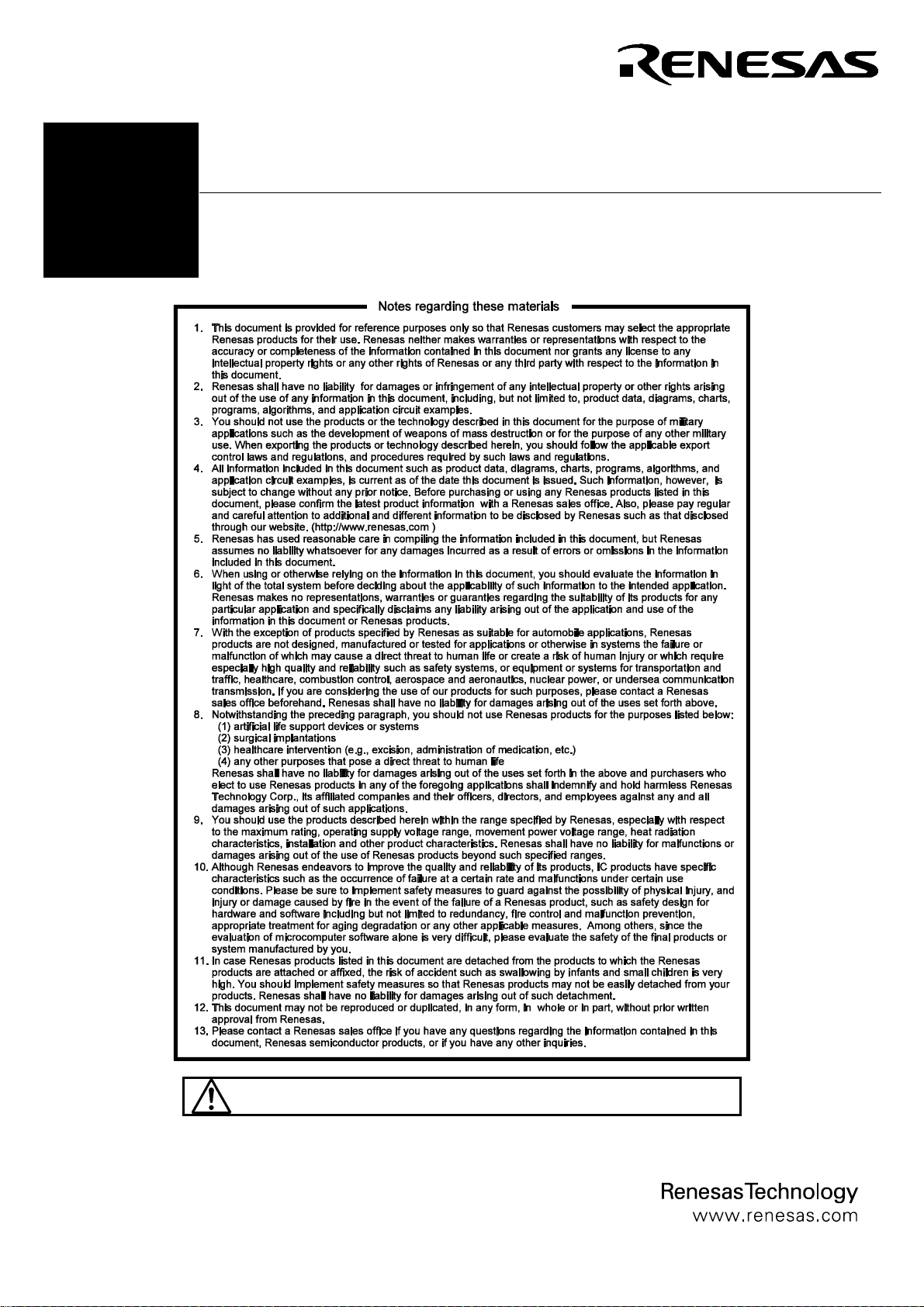
2. Package Components (see Figure 1)
(1) DIRECT80S main unit (16.8x16.8mm)
(2) DIRECT80S User's Manual (this manual)
3. Specifications
Table 1 Specifications
Item
Package
Max. current
Insertion/removal
iterations of connector
Insulation resistance
4. Application
(80-pin 0.65mm-pitch QFP)
(see Figure 2)
Description
8
200mA, 5V
20 times guaranteed
100MΩ or over
Mount this dummy IC on the foot pattern on the target.
Then connect the emulation pod at the top of dummy IC.
Before using M3T-DIRECT80S, be sure to read the
precautions on page 3.
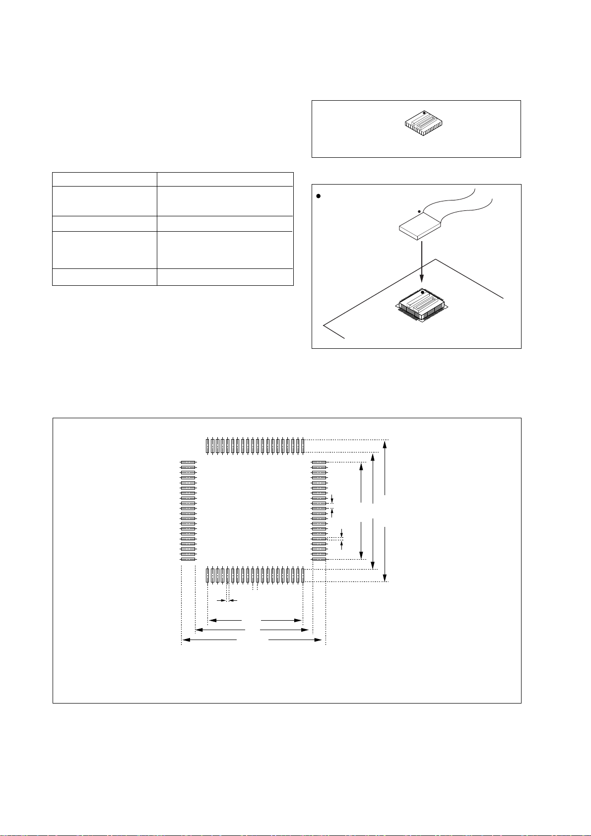
5. Target Foot Pattern
Figure 3 shows the recommended foot pattern of M3T-DIRECT80S.
M3T-DIRECT80S main unit
Figure 1 Package components of M3T-DIRECT80S
: position of No 1 pin
Be sure to m atch the position of
No. 1 pin of the foot pattern and
each part.
Emulator
M3T-DIRECT80S
Figure 2 Usage of M3T-DIRECT80S
0.65±0.05
0.35±0.05
12.35
14.6
Min. 17.5
Note: The recommended foot pattern of M3T-DIRECT80S is a common foot pattern for 80P6
S-A and M3T-DIRECT80S. For DUMMY80S, use the foot pattern recommended by
Matsushita Electric Works, Ltd. shown in the DUMMY80S User's Manual.
Figure 3 Recommended foot pattern of M3T-DIRECT80S
(2/4)
0.65
0.35
14.6
12.35
Min. 17.5
Page 3

6. Precaut ions
Note:
Some part numbers in this user's manual can be referred to as the following.
In this manual
DIRECT80S
Actual part number
M3T-DIRECT80S
->
CAUTION
Caution To Be Taken for This Product:
• Before mounting the M3T-DIRECT80S, be sure to check the pin positions.
IMPORTANT
Notes for This Product:
• We cannot accept any request for repair.
• For inquiries about the product or the contents of this manual, contact your local distributor.
Renesas Tools Homepage http://www.renesas.com
7. External Dimensions of M3T-DIRECT80S
A
20
1
1
25 26
D
6180
50
150
2625
4021
60
E
41
/tools
Symbol
12550261
J
2
255026
A
D
E
e
M
J
1
Dimension [mm]
4.9
16.8
16.8
0.65
6.3
Upper connector J1:
AXN650585P
(made by Matsushita Electric Works, Ltd.)
Upper connector J2:
AXN550045P
(made by Matsushita Electric Works, Ltd.)
e
M
1
: Pin No. of M3T-DIRECT80S
: Pin No. of upper connector
1
Figure 4 External dimensions of M3T-DIRECT80S
Board
Upper connector
(J1, J2)
(3/4)
Material: Glass epoxy board
Material: Heat tolerant resin (body)
Copper alloy (post, contact)
Plating: Nickel-based, gold plating
Page 4

8. Correspondence of Connectors J1 and J2
Table 2 lists the correspondence of M3T-DIRECT80S and connectors J1, J2.
Table 2 Correspondence of M3T-DIRECT80S and connectors J1, J2
Connector
pin No.
J1-1
J1-2
J1-3
J1-4
J1-5
J1-6
J1-7
J1-8
J1-9
J1-10
J1-11
J1-12
J1-13
J1-14
J1-15
J1-16
J1-17
J1-18
J1-19
J1-20
J1-21
J1-22
J1-23
J1-24
J1-25
DIRECT80S
pin No.
63
64
65
66
67
68
69
70
NC
NC
NC
NC
NC
NC
NC
NC
NC
31
32
33
34
35
36
37
38
Connector
pin No.
J1-26
J1-27
J1-28
J1-29
J1-30
J1-31
J1-32
J1-33
J1-43
J1-44
J1-45
J1-46
J1-47
J1-48
J1-49
J1-50
DIRECT80S
pin No.
NC
39
40
41
42
43
44
45
46
47
48
49
50
51
52
53
54
55
56
57
58
59
60
61
62
Connector
pin No.
J2-1
J2-2
J2-3
J2-4
J2-5
J2-6
J2-7
J2-8
J2-9
J2-10
J2-11
J2-12
J2-13
J2-14
J2-15
J2-16
J2-17
J2-18
J2-19
J2-20
J2-21
J2-22
J2-23
J2-24
J2-25
DIRECT80S
pin No.
79
80
1
2
3
4
5
6
7
8
9
10
11
12
13
14
15
16
17
18
19
20
21
22
NC
Connector
pin No.
J2-26
J2-27
J2-28
J2-29
J2-30
J2-31
J2-32
J2-33
J2-34
J2-35
J2-36
J2-37
J2-38
J2-39
J2-40
J2-41
J2-42
J2-43
J2-44
J2-45
J2-46
J2-47
J2-48
J2-49
J2-50
(NC: not connected)
DIRECT80S
pin No.
23
24
25
26
27
28
29
30
NCJ1-34
NCJ1-35
NCJ1-36
NCJ1-37
NCJ1-38
NCJ1-39
NCJ1-40
NCJ1-41
NCJ1-42
71
72
73
74
75
76
77
78
9. Recommended Procedure for Soldering M3T-DIRECT80S
(1) Fix the soldering position
Effect tack soldering.
(2) Apply the flux
Flux
• Apply flux to the semicircular through holes on the four sides.
(3) Solder
• Use a soldering iron having a large contact surface.
• Move the soldering iron in parallel with each surface
(with a feeling of causing the solder to flow).
• Pressing the semicircular through holes hard may cause them to get
crushed, so be careful.
• Make certain that no solder bridges are present.
(4/4)
 Loading...