

Page 1
M3T-64DIP-DMS
Converter Board for Connecting 64-pin RSS Type Emulator MCU to 64-pin 0.8mm pitch QFP
User’s Manual
CAUTION
Renesas Tools Homepage http://www.renesas.com/tools
Rev.2.00
Aug. 01, 2007
REJ10J0334-0200
If the requirements shown in the "CAUTION" sentences are ignored,
the equipment may cause personal injury or damage to the products.
(1/4)
Page 2
1. Description
PRQP0064GA-A (formerly: 64P6N-A)
M3T-64DIP-DMS is a converter board to connect the
64-pin RSS t ype em ulator MCU to the DUMMY64
(not included). Using the DUMMY64, the
M3T-64DIP-DMS converts the pin assignments
of an emulator MCU for the 64-pin 0.8mm pitch QFP.
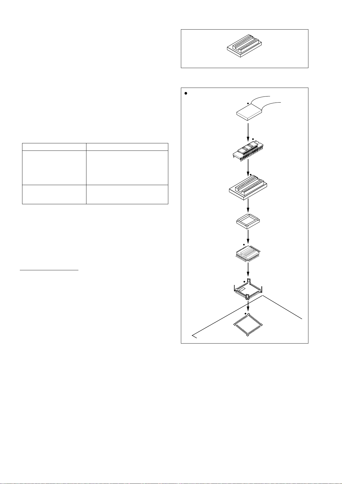
M3T-64DIP-DMS main unit
Figure 1 Package components of M3T-64DIP-DMS
2. Package Components (see Figure 1)
(1) 64DIP-DMS converter board
(2) 64DIP-DMS User's Manual (this manual)
3. Specifications
Table 1 Specifications
Item Description
P
Package
(64-pin 0.8mm pitch QFP)
64D0
(64-pin 0.8mm pitch QFN)
Insertion/removal
iterations of connector
20 times guaranteed
4. Application (see Figure 2)
Mount DUMMY64 on the QFP socket on the target, then
connect it to the probe of the emulation pod.
: position of No. 1 pin
Be sure to m atch the position of
No. 1 pin of the foot pattern and
each pin.
M38000TL2-FPD
(5)
Emulator MCU
(4)
64DIP-DMS
(6)
Socket frame
(3)
5. Connection Procedure (see Figure 2)
To mount QFP socket
(1) Mount the socket on the target.
* Be sure to prepare a foot pattern for holding
devices (4 corners) to solder the socket.
(2) Mount the DUMMY64 on the socket.
(3) Attach the socket frame to the socket.
(4) Mount an emulator MCU on the 64DIP-DMS.
(5) Connect the M38000TL2-FPD to the 64DIP-DMS.
(6) Connect the M3T-64DIP-DMS to the DUMMY64.
DUMMY64 main unit
(2)
Socket
(1)
Foot pattern
Figure 2 Usage of M3T-64DIP-DMS
(2/4)
Page 3
7. External Dimensions of M3T-64DIP-DMS
6
E
J1
64DIP-DMS REV.A
1
RESET
GND
X2
D
C1
C3
R1
X1
32
MADE IN JAPAN
C4
R2
C2
64
33
A
Symbol
A
B
C
B
E
M
D
Dimension [mm]
10.0
31.0
9.0
62.0
35.0
6.3
GND
J3
CM
* With a 3-pin oscillator used for X1, C1 and C2 are not mounted.
Figure 3 External dimensions of M3T-64DIP-DMS
J2
RESET
GND
R1
X2
C3 C4
R2
X1
C1 C2
RESET
Xcin
Xcout
Xin
Xout
GND
J1-27
J1-28
J1-29
J1-30
J1-31
J1-32
(3/4)
Page 4
6. Precautions
7
Note:
Some part numbers in this user's manual can be referred to as the following.
In this manual
64DIP-DMS
DUMMY64
->
->
Actual part number
M3T-64DIP-DMS
M3T-DUMMY64
Notes for This Product:
• We cannot accept any request for repair.
• For inquiries about the product or the contents of this manual, contact your local distributor.
IMPORTANT
Renesas Tools Homepage http://www.renesas.com
8. Correspondence of Connectors J1, J2 and J3
Table 2 lists the correspondence of connectors J1, J2 and J3
Table 2 Correspondence of connectors J1, J2 and J3
J1
connector
pin No.
J1-1
J1-2
J1-3
J1-4
J1-5
J1-6
J1-7
J1-8
J1-9
J1-10
J1-11
J1-12
J1-13
J1-14
J1-15
J1-16
* Pins of J2 and J3 connectors not listed here are not assigned.
J2, J3
connector
pin No.
J3-31
J3-32
J3-33
J3-34
J3-35
J3-36
J3-37
J3-38
J3-3
J3-4
J3-5
J3-6
J3-7
J3-8
J3-9
J3-10
J1
connector
pin No.
J1-17
J1-18
J1-19
J1-20
J1-21
J1-22
J1-23
J1-24
J1-25
J1-26
J1-27
J1-28
J1-29 J3-27
J1-30 J1-46
J1-31
J1-32 J3-30
J2, J3
connector
pin No.
J3-11
J3-12
J3-13
J3-14
J3-15
J3-16
J3-17
J3-18
J3-23
J3-24
J3-25
J3-26
J3-28
J3-29
J1
connector
pin No.
J1-33
J1-34
J1-35
J1-36
J1-37
J1-38
J1-39
J1-40
J1-41
J1-42
J1-43
J1-44
J1-45
J1-47
J1-48
/tools
J2, J3
connector
pin No.
J2-11
J2-12
J2-13
J2-14
J2-15
J2-16
J2-17
J2-18
J2-23
J2-24
J2-25
J2-26
J2-27
J2-28
J2-29
J2-30
J1
connector
pin No.
J1-49
J1-50
J1-51
J1-52
J1-53
J1-54
J1-55
J1-56
J1-57
J1-58
J1-59
J1-60
J1-61
J1-62
J1-63
J1-64
J2, J3
connector
pin No.
J2-31
J2-32
J2-33
J2-34
J2-35
J2-36
J2-37
J2-38
J2-3
J2-4
J2-5
J2-6
J2-7
J2-8
J2-9
J2-10
(4/4)
 Loading...