

Page 1

To our customers,
Old Company Name in Catalogs and Other Documents
On April 1st, 2010, NEC Electronics Corporation merged with Renesas Technology
Corporation, and Renesas Electronics Corporation took over all the business of both
companies. Therefore, although the old company name remains in this document, it is a valid
Renesas Electronics document. We appreciate your understanding.
Renesas Electronics website: http://www.renesas.com
April 1
Renesas Electronics Corporation
Issued by: Renesas Electronics Corporation (http://www.renesas.com)
st
, 2010
Send any inquiries to http://www.renesas.com/inquiry
.
Page 2

Notice
1. All information included in this document is current as of the date this document is issued. Such information, however, is
subject to change without any prior notice. Before purchasing or using any Renesas Electronics products listed herein, please
confirm the latest product information with a Renesas Electronics sales office. Also, please pay regular and careful attention to
additional and different information to be disclosed by Renesas Electronics such as that disclosed through our website.
2. Renesas Electronics does not assume any liability for infringement of patents, copyrights, or other intellectual property rights
of third parties by or arising from the use of Renesas Electronics products or technical information described in this document.
No license, express, implied or otherwise, is granted hereby under any patents, copyrights or other intellectual property rights
of Renesas Electronics or others.
3. You should not alter, modify, copy, or otherwise misappropriate any Renesas Electronics product, whether in whole or in part.
4. Descriptions of circuits, software and other related information in this document are provided only to illustrate the operation of
semiconductor products and application examples. You are fully responsible for the incorporation of these circuits, software,
and information in the design of your equipment. Renesas Electronics assumes no responsibility for any losses incurred by
you or third parties arising from the use of these circuits, software, or information.
5. When exporting the products or technology described in this document, you should comply with the applicable export control
laws and regulations and follow the procedures required by such laws and regulations. You should not use Renesas
Electronics products or the technology described in this document for any purpose relating to military applications or use by
the military, including but not limited to the development of weapons of mass destruction. Renesas Electronics products and
technology may not be used for or incorporated into any products or systems whose manufacture, use, or sale is prohibited
under any applicable domestic or foreign laws or regulations.
6. Renesas Electronics has used reasonable care in preparing the information included in this document, but Renesas Electronics
does not warrant that such informatio n is error free. Renesas Electronics assumes no liability whatsoever for any damages
incurred by you resulting from errors in or omissions from the information included herein.
7. Renesas Electronics products are classified according to the following three quality grades: “Standard”, “High Quality”, and
“Specific”. The recommended applications for each Renesas Electronics product depends on the product’s quality grade, as
indicated below. You must check the quality grade of each Renesas Electronics product before using it in a particular
application. You may not use any Renesas Electronics product for any application categorized as “Specific” without the prior
written consent of Renesas Electronics. Further, you may not use any Renesas Electronics product for any application for
which it is not intended without the prior written consent of Renesas Electronics. Renesas Electronics shall not be in any way
liable for any damages or losses incurred by you or third parties arising from the use of any Renesas Electronics product for an
application categorized as “Specific” or for which the product is not intended where you have failed to obtain the prior written
consent of Renesas Electronics. The quality grade of each Renesas Electronics product is “Standard” unless otherwise
expressly specified in a Ren esas E lectronics data sheets or dat a books, etc.
“Standard”: Computers; office equipment; communications equipment; test and measurement equipment; audio and visual
equipment; home electron ic appliances; machine tools; personal electronic equipment; and industrial robots.
“High Quality”: Transportation equipment (automobiles, trains, ships, etc.); traffic control systems; anti-disaster systems; anti-
crime systems; safety equipment; and medical equipment not specifically designed for life support.
“Specific”: Aircraft; aerospace equipment; submersible repeaters; nuclear reactor control systems; medical equipment or
systems for life support (e.g. artificial life support devices or systems), surgical implantations, or healthcare
intervention (e.g. excision, etc.), and any other appl i cations or purposes that pose a d irect threat to human life.
8. You should use the Renesas Electronics products described in this document within the range specified by Renesas Electronics,
especially with respect to the maximum rating, operating supply voltage range, movement power voltage range, heat radiation
characteristics, installation and other product characteristics. Renesas Electronics shall have no liability for malfunctions or
damages arising out of the use of Renesas Electronics products beyond such specified ranges.
9. Although Renesas Electronics endeavors to improve the quality and reliability of its products, semiconductor products have
specific characteristics such as t he occu rrence o f failure at a certai n rate an d malfunct io ns under cert ain u se con dition s. Further,
Renesas Electronics prod ucts are not subject to radiation resistance design. Please be sure to implement safety measures to
guard them against the possibility of physical injury, and injury or damage caused by fire in the event of the failure of a
Renesas Electronics product, such as safety design for hardware and software including but not limited to redundancy, fire
control and malfunction prevention, appropriate treatment for aging degradation or any other appropriate measures. Because
the evaluation of microcomputer software alone is very difficult, please evaluate the safety of the final products or system
manufactured by you.
10. Please contact a Renesas Electronics sales office for details as to environmental matters such as the environmental
compatibility of each Renesas Electronics product. Please use Renesas Electronics products in compliance with all applicable
laws and regulations that regulate the inclusion or use of controlled substances, including without limitation, the EU RoHS
Directive. Renesas Electronics assumes no liability for damages or losses occurring as a result of your noncompliance with
applicable laws and regulations.
11. This document may not be reproduced or duplicated, in any form, in whole or in part, without prior written consent of Renesas
Electronics.
12. Please contact a Renesas Electronics sales office if you have any questions regarding the information contained in this
document or Renesas Electronics products, or if you have any other inquiries.
(Note 1) “Renesas Electronics” as used in this document means Renesas Electronics Corporation an d also includes its majority-
owned subsidiaries.
(Note 2) “Renesas Electronics product(s)” means any product developed or manufactured by or for Renesas Electronics.
Page 3

User’s Manual
SH7670 CPU Board
M3A-HS71
Installation Manual
Renesas 32-Bit RISC Microcomputers
SuperH™ RISC engine Family/SH7670 Series
Rev.1.01 2008.05
Page 4

Page 5

Page 6

Page 7
[Indication of Warnings and Cautions]
The following explains the warnings and cautions indicated for the handling of the product.
If the product is improperly handled without regard for this indication, there will be a
WANING
CAUTION
IMPORTANT
In addition to the above, the following will be indicated as necessary.
The mark indicates a warning or caution.
Example:
possibility of inflicting death or heavy wound on persons.
If the product is improperly handled without regard for this indication, there will be a
possibility of inflicting an injury on persons or physical damage.
Indicates other important information to be observed when using the product.
Be Careful About Electric Shock
The mark indicates a prohibition.
Example:
The mark indicates a compulsory or directive instruction.
Example:
Do Not Disassemble
Unplug from Socket
Page 8

Page 9

Important
Before using this product, be sure to read the user’s manual (this user's manual) carefully. Keep this user’s
manual, and refer to this when you have questions about this product.
About this product:
The term “this product” referred to here mean the product manufactured by Renesas Technology
Corporation.
It does not include the user systems and host machines of the customers.
Purpose of use of this product:
This product is developed for experiencing the development environment and specification of the Renesas
32-bit RISC MCU SuperH RISC engine family /SH7670. Be sure to use this product correctly according to
said purpose of use. Please avoid using this product for other than its intended purpose of use.
For those who use this product:
This product can only be used by those who have carefully read the user’s manual and know how to use it.
Use of this product requires the basic knowledge of electric circuits, logical circuits, and MCUs.
When using this product:
(1) This product is a development supporting unit for use in your program development and evaluation
stages.
In mass-producing your program you have finished developing, be sure to make a judgment on your own risk
that it can be put to practical use by performing integration test, evaluation, or some experiment else.
(2) In no event shall Renesas Solutions Corp. be liable for any consequence arising from the use of this
product.
(3) This product has been developed by assuming its use for program development and ev aluation in
laboratories. Therefore, it does not fall under the application of Electrical Appliance and Material Safety Law
and protection against electromagnetic interference when used in Japan.
(4) Renesas Solutions Corp. cannot predict all possible situations or possible cases of misuse where a
potential danger exists. Therefore, the warnings written in this user’s manual and the warning labels attached
to this product do not necessarily cover all of such possible situations or cases. Please be sure to use this
product correctly and safely on your own responsibility.
(5) This product is designed for use in program development and evaluation stages. It cannot be embedded
in your product for mass-production purposes.
(6) Even if this product has a deficiency in its internal microcomputer, it will not be replaced with a product
which has had the microcomputer deficiencies corrected.
(7) No parts incorporated in this product may be dismantled for diverted use in other products.
(8) For the products with socket mounted, it is likely to become a loose connection by the vibration and the
shocking In this case, please reinstalls IC again.
Page 10

Page 11

Usage restrictions:
This product has been developed as a means of supporting system development by users. Therefore, do not
use it as a device used for equipment-embedded applications. Also, do not use it for developing the systems
or equipment used for the following purposes either:
(1) Transportation and vehicular
(2) Medical (equipment where human life is concerned)
(3) Aerospace
(4) Nuclear power control
(5) Undersea repeater
If you are considering the use of this product for one of the above purposes, please be sure to consult your
local distributor.
About product changes:
We are constantly making efforts to improve the design and performance of this product. Therefore, the
specification or design of this product or its user’s manual may be changed without prior notice.
About the rights:
(1) We assume no responsibility for any damage or infringement on patent rights or any other rights arising
from the use of any information, products or circuits presented in this user’s manual.
(2) The information or data in this user’s manual does not implicitly or otherwise grant a license for patent
rights or any other rights belonging to us or third parties.
(3) This user’s manual and this product are copyrighted, with all rights reserved by us. This user’s manual
may not be copied, duplicated or reproduced, in whole or part, without prior written consent of us.
About diagrams:
The diagrams in this user’s manual may not all represent exactly the actual object.
Page 12

Page 13

Table of Contents
CHAPTER1 BEFORE USING THE SH7670 CPU BOARD.................................................................1-1
1.1 Overview......................................................................................................................................................................1-2
1.2 Usage Precautions.......................................................................................................................................................1-2
1.2.1 Symbols Used ...................................................................................................................................................... 1-3
1.3 Procedure for Introducing This Product........................................................................................................................ 1-4
1.4 Operating Guarantee for This Product .........................................................................................................................1-4
1.5 Items to Be Prepared by User...................................................................................................................................... 1-5
1.5.1 Recommended Host Computer Environment ....................................................................................................... 1-5
CHAPTER2 SETTING UP THE HARDWARE.....................................................................................2-1
2.1 Connections Between SH7670 CPU board and E10A-USB Emulator ......................................................................... 2-2
2.2 SH7670 CPU board Switch Setting.............................................................................................................................. 2-2
2.2.1 SH7670 CPU board DIP Switch Setting ............................................................................................................... 2-3
2.2.2 SH7670 CPU Board Jumper Switch Setting.........................................................................................................2-3
2.3 System Connections and Power-On Sequence...........................................................................................................2-4
2.4 Procedure for Disconnecting System Power Supply....................................................................................................2-4
CHAPTER3 SETTING UP THE SOFTWARE .....................................................................................3-1
3.1 About the HEW ............................................................................................................................................................3-2
3.1.1 HEW Installation Procedure.................................................................................................................................. 3-2
3.2 Setting Up the E10A-USB Emulator Software.............................................................................................................. 3-5
3.2.1 E10A-USB Software Installation Procedure.......................................................................................................... 3-5
3.2.2 Setting Up the E10A-USB Emulator ..................................................................................................................... 3-9
CHAPTER4 RUNNING THE SOFTWARE ..........................................................................................4-1
4.1 Running the Software................................................................................................................................................... 4-2
4.1.1 Preparing for Downloading the Sample Software.................................................................................................4-2
4.1.2 SH7670 CPU board and E10A-USB Startup Procedure (HEW Startup)............................................................... 4-2
4.1.3 E10A-USB Emulator Connection Error Dialog...................................................................................................... 4-6
4.1.4 Sample Software Download Procedure................................................................................................................4-8
CHAPTER5 CREATING AND RUNNING A NEW PROJECT WORKSPACE.....................................5-1
5.1 Creating a New Project Workspace ............................................................................................................................. 5-2
5.1.1 Preparing for Creating a New Project Workspace ................................................................................................ 5-2
5.1.2 Procedure for Creating a New Project Workspace ............................................................................................... 5-2
5.2 Setting Up the Flash Memory Download...................................................................................................................... 5-8
5.2.1 Setting Up the Flash Memory Download Function................................................................................................ 5-8
5.2.2 Specifying the Command Batch File Before Downloading.................................................................................... 5-9
Rev. 1.01 May 7, 2008
REJ1 1J0015-0101
(i)
Page 14

5.2.3 Activating the Command Line Window...............................................................................................................5-10
5.3 Adding/Modifying Hardware Setup Files .................................................................................................................... 5-10
5.3.1 Copying Hardware Setup Files...........................................................................................................................5-10
5.3.2 Removing the Standard Source Files.................................................................................................................5-10
5.3.3 Adding Hardware Setup Files..............................................................................................................................5-11
5.3.4 Setting Compiler Options....................................................................................................................................5-13
5.3.5 Setting Linker Options ........................................................................................................................................ 5-14
5.3.6 Writing the Main Function (Operation Confirmation)........................................................................................... 5-21
Rev. 1.01 May 7, 2008
REJ1 1J0015-0101
(ii)
Page 15

*This page is blank*
Rev. 1.01
REJ1 1J0015-0101
May 7, 2008
iii
(
)
Page 16

Page 17

Chapter1Before Using the SH7670 CPU Board
Chapter1
Before Using the SH7670 CPU Board
1-1
Page 18
Before Using the SH7670 CPU Board
1
1.1 Overview
1.1 Overview
The SH7670 CPU board(board type name: M3A-HS71) consists of the SH7670 CPU board and the sample software.
This installation manual describes mainly how to set up the SH7670 CP U board hardware and soft ware. For more
information about SH7670 hardware and programming manual, refer to the manuals in CD-ROM included with this
product.
If there is anything that you notice about the package contents of this product, please contact Renesas Technology
Corporation, Renesas Solutions Corporation, or Renesas Technology Sales Co., Ltd. or its distributor.
To Ensure Safe and Correct Use
Safety precaution:
z This manual uses various pictorial indications to ensure the correct use of the product and
thereby prevent inflicting an injury on users or other people or causing da mage to property.
• These pictorial indications are explained in the section 1.2, “Usage Precautions.” Please be sure
to understand the contents written in that section before you use the product.
1.2 Usage Precautions
The precautions described here must be observed in order to prevent inflicting an injury on users or other people or
causing damage to property, and to ensure that this product is used safely.
To ensure the correct use, be sure to read these precautions and understand the written contents before you use the
product. Not all precautions described in this manual relate to the Renesas product alone, some of them apply to an
entire personal computer system incorporating the Renesas product also.
The following explains the warnings and cautions indicated for the handling of this product.
<Warning Indication>
Regarding the handling of this product:
z Do not use this product outdoors. It can only be used indoors.
• Do not let foreign matters such as water, pieces of metal or inflammable material get into the
board or connectors.
Regarding installation:
• Do not install t he product in h umid or wet places. Should water get int o the internal circ uit of the
product, an unrecoverable fault may result.
Regarding the working environment:
• The upper-limit ambient temperature at which this product can be used (i.e., rated maximum
ambient temperature) is 50°C. Make sure this rated maximum ambient temperature is not
exceeded.
WARNING
Rev. 1.01 May 7, 2008
REJ1 1J0015-0101
1-2
Page 19

1
<Caution Indication>
Regarding the reconstruction of this product:
• Do not reconstruct this product. If the product has gotten out of order for reasons of disassembly
or reconstruction, requests for repair may not be accepted.
Regarding the handling of this product:
z Handle this product with caution, not to let it drop or fall down or apply strong mechanical shock.
z Do not touch the communication interface connector pins or other connector pins directly with
your hand. The internal circuit may be broken by static electricity.
z When moving this product to another place of installation, be careful not to apply strong vibration
or mechanical shock to it.
z After connecting each piece of equipment with cable, check the cables again to see that they are
connected correctly. For details on how to connect, refer to Chapter 2, “Setting Up the Hardware.”
z Before turning on the power for each connected piece of equipment, make sure you’ve finished
connecting all cables. Do not connect or disconnect any cable when the power is turned on.
Regarding the operating procedure for this product:
Note • Exceptional conditions or precautions are noted in an operation procedure or explanatory
description when it is necessary to call the user’s attention.
1.2.1 Symbols Used
Table 1.2.1 lists the symbols used in this manual.
Before Using the SH7670 CPU Board
1.2.1 Symbols Used
CAUTION
Table 1.2.1 Symbol List
[Menu->Menu Option]
“File name”
“Directory”
“Button"
Symbol Meaning
The arrow “Æ” indicates a menu option.
Example: File menuÆSave As…
" … " indicates file names, directory, or button of dialog box.
Example :"C:¥Workspace¥Sample_softwawe¥ SH7670_sample "
"OK" button
"resetprg.c"
Rev. 1.01 May 7, 2008
REJ1 1J0015-0101
1-3
Page 20
1
1.3 Procedure for Introducing This Product
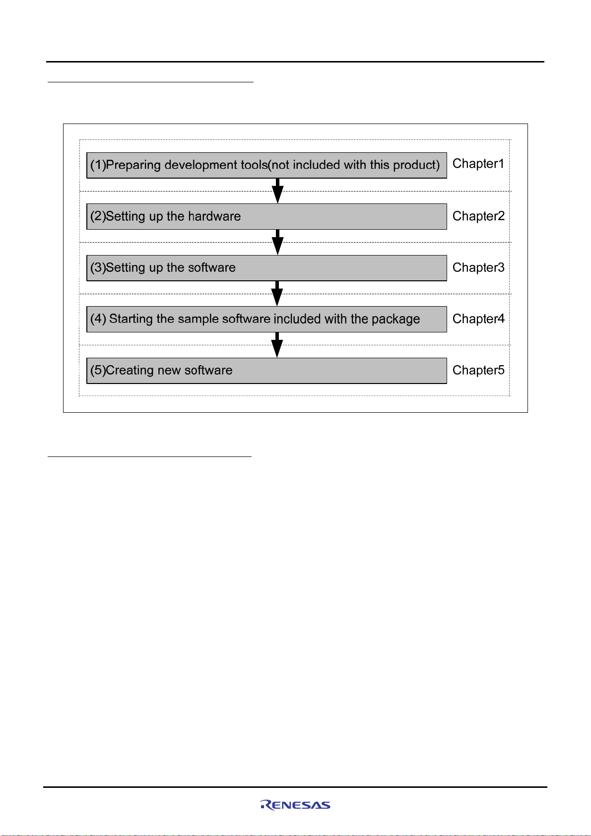
In this manual, we follow the procedure outlined in
Before Using the SH7670 CPU Board
1.3 Procedure for Introducing This Product
Figure 1.3.1 to perform the installation.
Figure 1.3.1 SH7670 CPU board Installation Procedure
1.4 Operating Guarantee for This Product
This product (hardware and software) was developed for only helping users get hands-on experience on the
functionality and development environment of the SH7670, and does not guarantee the results arising from the use of it.
The SH7670 CPU board has the type of host computer designated as its operating environment (IBM PC/AT and its
compatible). This only indicates the operating environment assumed by Renesas, and d oes not guarantee that the
SH7670 CPU board will operate normally in all relevant types of machines or in all relevant environments (e.g., device
driver and peripheral device).
Rev. 1.01 May 7, 2008
REJ1 1J0015-0101
1-4
Page 21
Before Using the SH7670 CPU Board
1
1.5 Items to Be Prepared by User
1.5 Items to Be Prepared by User
The following lists the items that need to be prepared by users separately from this product.
<For SH7670 CPU board>
You need to prepare the following power supply separately from the product package in order to supply power to the
SH7670 CPU board.
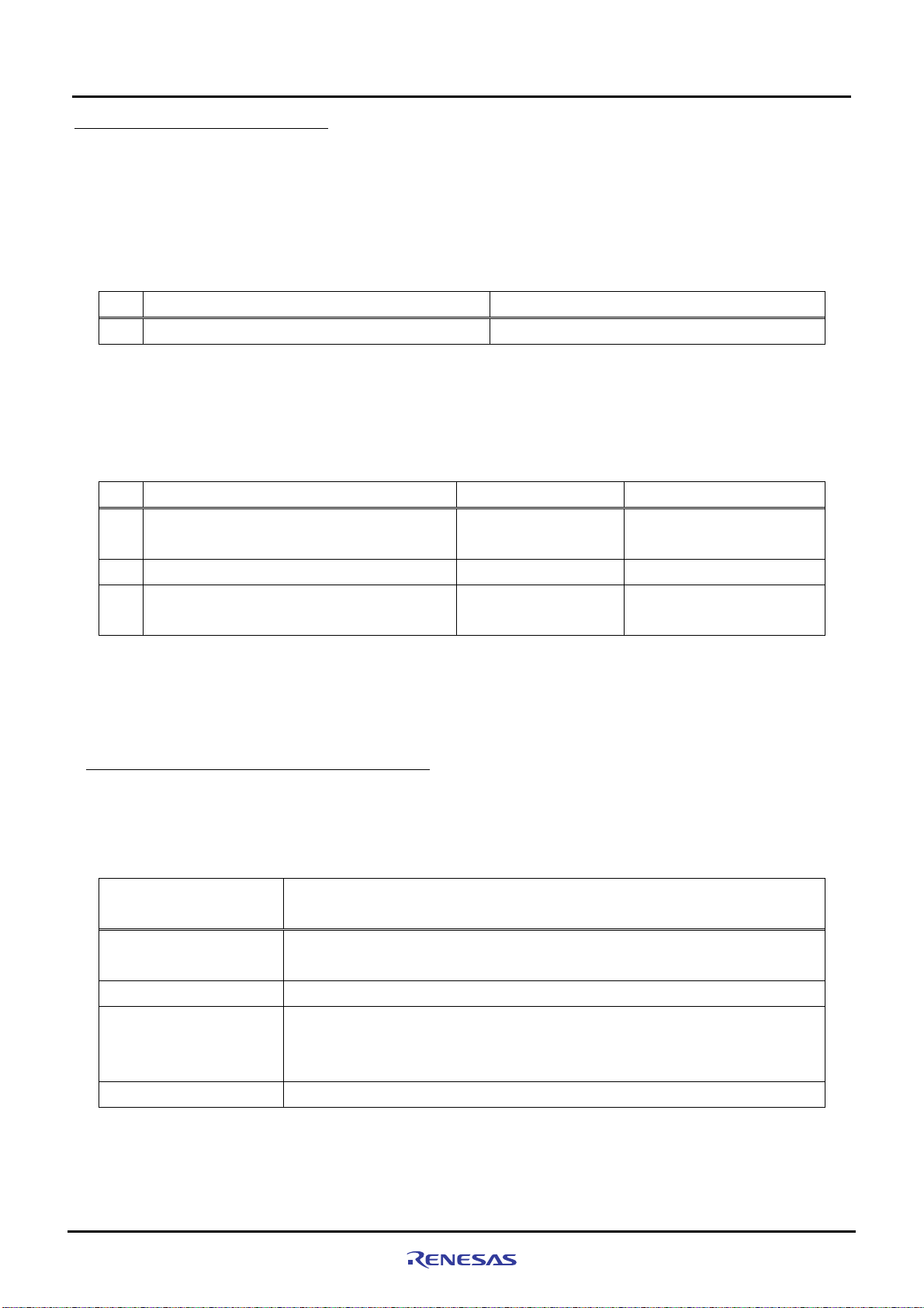
Table 1.5.1 Items to Be Prepared by User (For SH7670 CPU board)
No. Item to Be Prepared by User Remark
1
5 V DC output stabilizing power supply
<For the Development Environment>
The installation described here uses the tools made by Renesas.
To use this product following the installation, you need to prepare some items separately from the product package.
The table below lists the tools made by Renesas that users should prepare.
Table 1.5.2 Items to Be Prepared by User (Renesas Tools)
No. Item to Be Prepared by User
2
E10A-USB emulator for the SuperH family
3
SuperH RISC engine C/C++ compiler package
Integrated development environment tool,
4
HEW (High-performance Embedded Workshop)
Notes:
• If you already have the E10A-USB emulator main unit and are using any device group other than the SH-2A group,
you need to purchase an “additional device group license tool” separately from the product package.
• For details on how to set up a new device group in the E10A-USB emulator, refer to Section 3.2.2, “Setting Up the
E10A-USB Emulator” in Chapter 3 of this manual.
Product Type Name
HS0005KCU02H or
HS0005KCU01H
R0C40700XSW09R Ver.9.00 release01 or more
- Ver.4.03.00 or more
1.5 A
or more
Applicable Version
One that supports the
SH-2A
1.5.1 Recommended Host Computer Environment
To use the above Renesas tools, we recommend using the host computer and the OS version listed in
below.
Table 1.5.3 Operating Environment for the Renesas Development Tools
Host Computer
Specification
CPU
Memory
Hard disk capacity
OS Windows 2000, WindowsXP
IBM PC and its compatible incorporating Pentium III or later (600 MHz or greater
recommended) and USB 1.1/2.0 (Full Speed)
128 MB or more (at least twice the load module size recommended)
Installation requires 100 MB or more of hard disk capacity.
(With the swap area taken into consideration, at least twice the memory size must be
available (four times or more recommended).)
IBM PC/AT Series and Compatibles
Table 1.5.3
Rev. 1.01 May 7, 2008
REJ1 1J0015-0101
1-5
Page 22

1
Before Using the SH7670 CPU Board
1.5 Items to Be Prepared by User
*This page is blank*
Rev. 1.01 May 7, 2008 1-6
REJ1 1J0015-0101
Page 23

Chapter2Setting Up the Hardware
Chapter2
Setting Up the Hardware
2-1
Page 24
2
2.1 Connections Between SH7670 CPU board and E10A-USB Emulator
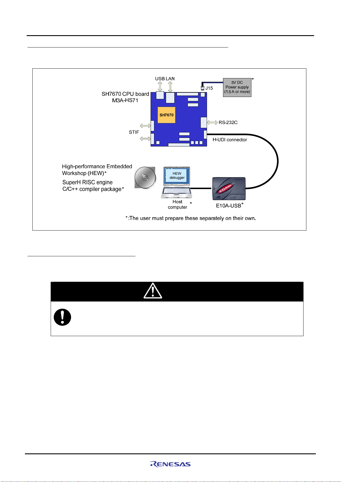
2.1 Connections Between SH7670 CPU board and E10A-USB Emulator
Figure 2.1.1 shows how SH7670 CPU board and E10A-USB emulator should be connected.
Setting Up the Hardware
Figure 2.1.1 System Connection of SH7670 CPU board and E10A-USB Emulator
2.2 SH7670 CPU board Switch Setting
The following describes how to set the switches of SH7670 CPU board.
CAUTION
• Do not change DIP switch and jumper settings while the SH7670 CPU board is operating. Always
be sure to turn off the power before changing DIP switch or jumper settings. This is necessary to
prevent unrecoverable damage to the SH7670 CPU board that may otherwise occur.
Rev. 1.01 May 7, 2008
REJ1 1J0015-0101
2-2
Page 25
Setting Up the Hardware
2
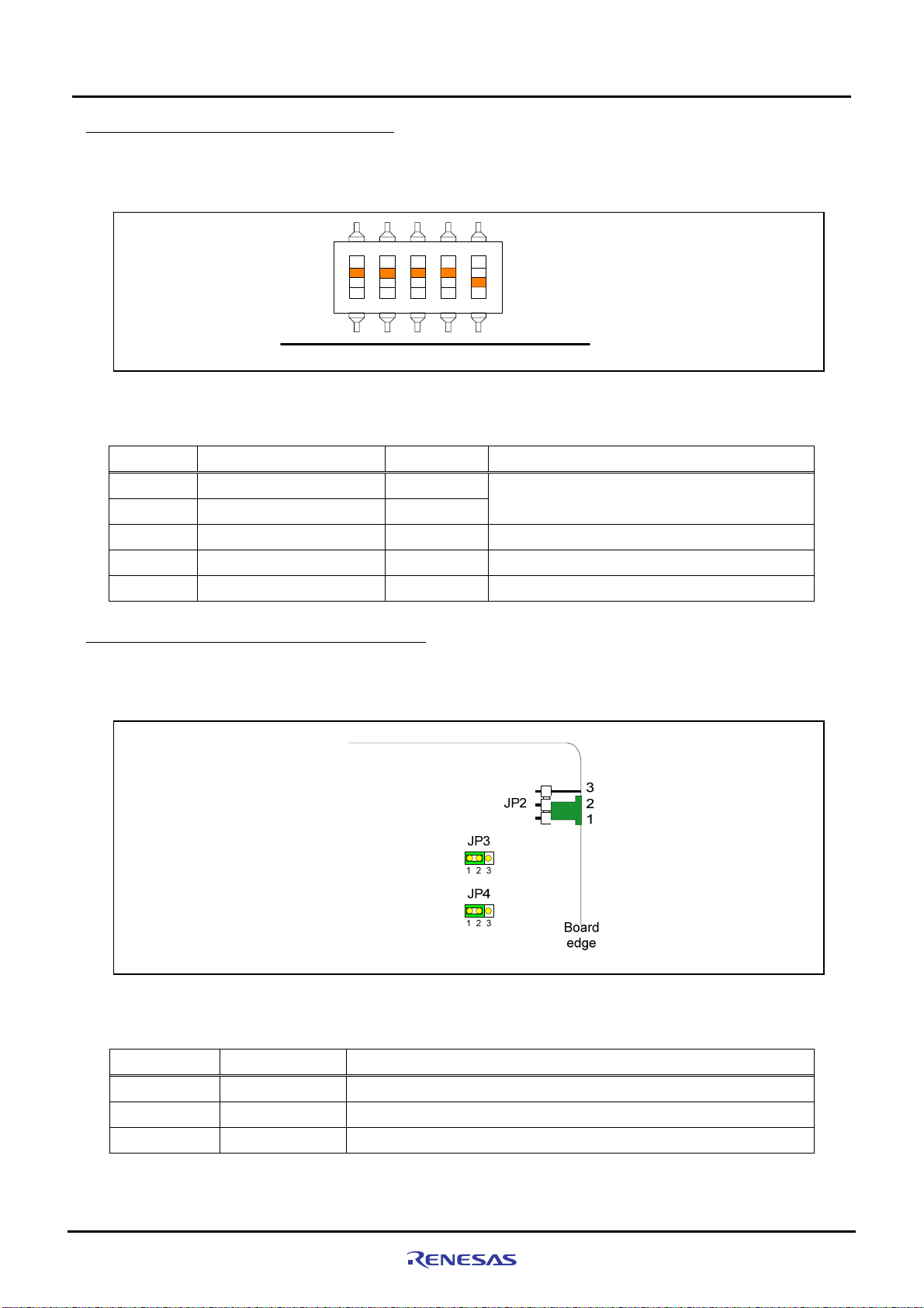
2.2.1 SH7670 CPU board DIP Switch Setting
To use the SH7670 CPU board following the installation described here, be sure to set the DIP switch SW8 to its
default settings as shown in
Switch No. Function Initial Settings Setting
Figure 2.2.1 and Table 2.2.1.
ON
SW8
Figure 2.2.1 DIP Switch Setting
Table 2.2.1 Switch SW8 Functions
2.2.1 SH7670 CPU board DIP Switch Setting
Board
edge
SW8-1 Set clock mode to 0 ON
SW8-2 Set clock mode to 1
SW8-3 HIF pin enable ON Cancel HIF pin activation
SW8-4 HIF boot mode specified ON Do not activate from host interface (HIF)
SW8-5 NOR flash memory OFF Cancel write protection in NOR flash memory
ON
Clock mode 0
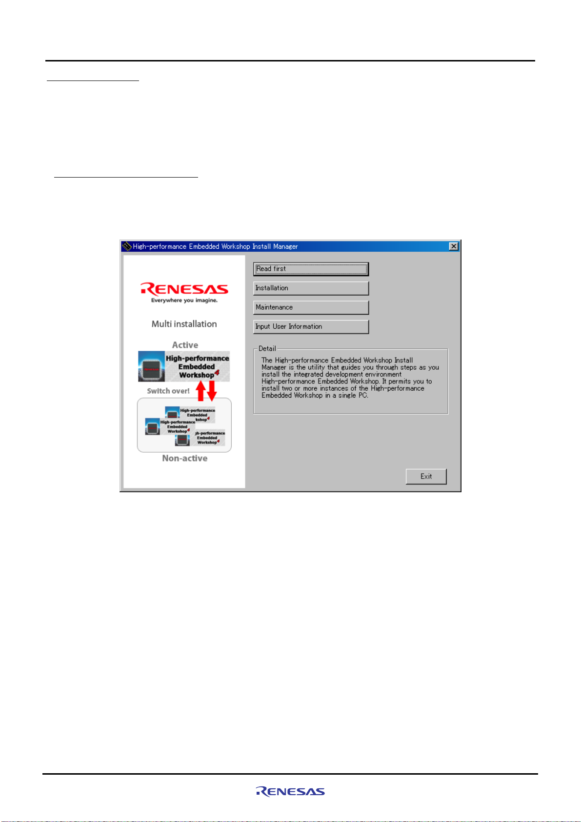
2.2.2 SH7670 CPU Board Jumper Switch Setting
To use the SH7670 CPU board following the installation described here, b e sure to set the jumpers to their default
settings as shown in
Jumper Default Setting Function
Figure 2.2.2 and Table 2.2.2.
Figure 2.2.2 System Connection of SH7670 CPU board and E10A-USB Emulator
Table 2.2.2 SH7670 Group Power Supply Selection Jumper Setting (JP2 to JP4)
JP2 1-2
JP3 1-2
JP4 1-2
Rev. 1.01 May 7, 2008
REJ1 1J0015-0101
Power supply from J15
3.3 V fixed power supply voltage (supplied from U10)
1.2 V fixed power supply voltage (supplied from U11)
2-3
Page 26

2
2.3 System Connections and Power-On Sequence
2.3 System Connections and Power-On Sequence
Follow the same procedure when you check to see that the power for the host computer is turned off, or that the
E10A-USB emulator is not connected to the host computer with USB cable.
1. Connect the SH7670 CPU board and the E10A-USB emulator with the user interface cable.
2. Plug the USB cable into the connector on the host side of the E10A-USB emulator.
3. Turn on the power for the host computer. (The OS will start up.)
4. Supply power to the SH7670 CPU board (by turning the POWER switch on).
2.4 Procedure for Disconnecting System Power Supply
Disconnect power supply as following procedure.
1. Disconnect E10A-USB on HEW (High-performance Embedded Workshop).
2. Turn off a CPU board.
3. Terminate a HEW, and turn off a host computer.
Setting Up the Hardware
CAUTION
• Unless the above power-on sequence is followed, unrecoverable damage may occur to the
SH7670 CPU board or the E10A-USB emulator or both.
Rev. 1.01 May 7, 2008
REJ1 1J0015-0101
2-4
Page 27

Chapter3Setting Up the Software
Chapter3
Setting Up the Software
3-1
Page 28
Setting Up the Software
3
3.1 About the HEW
3.1 About the HEW
HEW, or High-performance Embedded Workshop, is an integrated development environment with a graphical user
interface designed to help users develop and debug the applications created in C/C++ and assembly languages for use
in Renesas microcomputers. The SH7670 CPU board based so ftware development is ca rried out by using the HEW.
For more information about the HEW, refer to the “SuperH RISC Engine High-performance Embedded Workshop 4
User’s Manual”. The following shows how to install the HEW.
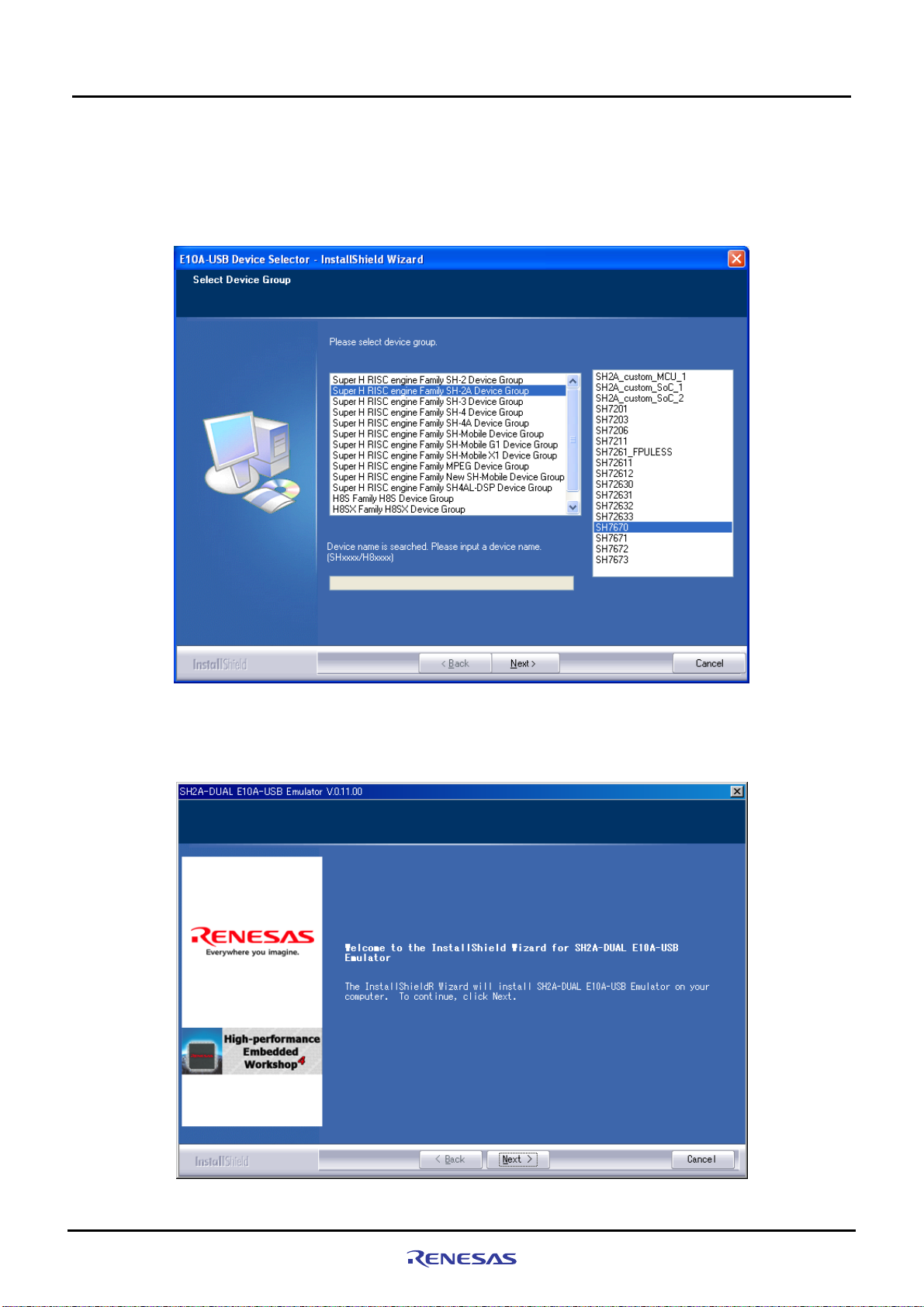
3.1.1 HEW Installation Procedure
(1) Execute “HewInstMan.exe” included in the cross tool (SuperH RISC engine C/C++ compiler pack age ) stored in th e
CD-ROM. High-performance Embedded Workshop Install Manager is activated, and click “Installation”.
Figure 3.1.1 HEW Installation Procedure (1)
Rev. 1.01 May 7, 2008
REJ1 1J0015-0101
3-2
Page 29

3
(2)
Figure 3.1.2 is displayed, and click “Next”.
Setting Up the Software
3.1 About the HEW
Figure 3.1.2 HEW Installation Procedure (2)
Note: If you have already installed a HEW on your PC, you can select “Install a ne w High-performance Embedded
Workshop” and install a new HEW in another directory on your PC.
(3) Continue to install following the instructions in the installation window.
(4) Next, install an Autoupdate Utility. Click “Next”.
Figure 3.1.3 HEW Installation Procedure (4)
Note: When you have not selected “Autoupdate” on the Choice of an installation pr oduct, the above dialog is not
displayed.
Rev. 1.01 May 7, 2008
REJ1 1J0015-0101
3-3
Page 30

Setting Up the Software
3
(5) Continue to install following the instructions in the installation window. When entire installation is finished, the dialog
shown in Figure 3.1.4 is displayed, click “Exit”.
3.1 About the HEW
Figure 3.1.4 HEW Installation Procedure (5)
Rev. 1.01 May 7, 2008
REJ1 1J0015-0101
3-4
Page 31

Setting Up the Software
3
3.2.1 E10A-USB Software Installation Procedure
3.2 Setting Up the E10A-USB Emulator Software
Next, the following explains how to set up the E10A-USB emulator software.
3.2.1 E10A-USB Software Installation Procedure
(1) Execute “HewInstMan.exe” included in the E10A-USB emulator software CD-ROM. High-performance Embedde d
Workshop Install Manager is activated, and click “Installation”.
Figure 3.2.1 E10A-USB Software Installation Procedure (3)
(2) When the dialog box shown in
Workshop” and click “Next”.
Figure 3.2.2 is displayed, select “Update the active High-performance Emb edded
Rev. 1.01 May 7, 2008
REJ1 1J0015-0101
Figure 3.2.2 E10A-USB Software Installation Procedure (2)
3-5
Page 32
Setting Up the Software
3
Note: If you have already installed a HEW on your PC, you can select “Install a ne w High-performance Embedded
Workshop” and install a new HEW in another directory on your PC.
(3) When the dialog box shown in Figure 3.2.3 is displayed, select “SuperH RISC engine Family SH-2A Device Group”
and “SH7670”, then click “Next”.
3.2.1 E10A-USB Software Installation Procedure
Figure 3.2.3 E10A-USB Software Installation Procedure (3)
(4) Click “Next to start the installation. Continue to install following the instructions in the installation window.
Rev. 1.01 May 7, 2008
REJ1 1J0015-0101
Figure 3.2.4 E10A-USB Software Installation Procedure (4)
3-6
Page 33

3
(5) Next, install an Autoupdate Utility. Click “Next”.
Setting Up the Software
3.2.1 E10A-USB Software Installation Procedure
Figure 3.2.5 E10A-USB Software Installation Procedure (5)
Note: When you have not selected “Autoupdate” on the Choice of an installation pr oduct, the above dialog is not
displayed.
(6) When the installation is complete, the dialog shown in
Figure 3.2.6 is displayed. Click “Finish”.
Rev. 1.01 May 7, 2008
REJ1 1J0015-0101
Figure 3.2.6 E10A-USB Software Installation Procedure (6)
3-7
Page 34

3
(7) When entire installation is finished, the dialog shown in Figure 3.2.7 is displayed, click “Exit”.
3.2.1 E10A-USB Software Installation Procedure
Setting Up the Software
Figure 3.2.7 E10A-USB Software Installation Procedure (7)
Rev. 1.01 May 7, 2008
REJ1 1J0015-0101
3-8
Page 35

Setting Up the Software
3
3.2.2 Setting Up the E10A-USB Emulator
(i) Setting Up New Firmware
The following explains the case where you set up new firmware of the E10A-USB emulator.
If your E10A-USB emulator already has the firmware suitable for the SH-2A group, skip this step and go to paragraph
(ii) “Setting Up the E10A-USB Emulator Driver.”
Firmware setup requires changing the DIP switch settings on the E10A-USB emulator main unit. Be c areful not to
mistake the part of the DIP switch that you need to set.
emulator.
Figure 3.2.8 shows the DIP switch mounted on the E10A-USB
3.2.2 Setting Up the E10A-USB Emulator
Figure 3.2.8 DIP Switch on the E10A-USB Emulator
Rev. 1.01 May 7, 2008
REJ1 1J0015-0101
3-9
Page 36

Setting Up the Software
3
(1) Open the slide switch cover on the E10A-USB emulator main unit, and check to see that the emulator setup switch
(SW1) is set to the “1” side.
(2) From [All Programs] on [Start menu], choose [Renesas High-performance Embedded Workshop] Æ
[Setup Tool for E10A-USB Emulator] Æ [SH-2A Device Group]. An E10A-USB emulator setup tool will start up.
Figure3.2.9 E10A-USB Emulator Setup Tool
(a) Device group of the emulator firmware : Shows the product group name that is currently set up.
(b) Version number of the emulator firmware : Shows the version of the SH-2A group control software in the
E10A-USB emulator.
(c) Version number of the setup program : Shows the version of the setup program.
Note: The version numbers differ with each device group supported by the E10A-USB emulator.
3.2.2 Setting Up the E10A-USB Emulator
(a)
(b)
(c)
Rev. 1.01 May 7, 2008
REJ1 1J0015-0101
3-10
Page 37

3
Setting Up the Software
3.2.2 Setting Up the E10A-USB Emulator
Notes
• If the versions shown in (b) and (c) are the same, you do not need to set up. If the version shown in (b) is “-.-.--.---”
or older than the version in (c), you need to set up.
• If the emulator connected to your system is not the E10A-USB emulat or suitable for the SH7670, the error
message shown below will be displayed, with the setup tool thereby terminated. In this case, you need to purchase
an “additional device group license tool” separately from the SH7670 CPU board package and use it to set up the
emulator firmware.
Figure3.2.10 Error Message
• If the error message shown below is displayed, it means that the host computer and the E10A-USB emulator are
not connected together, or the emulator setup switch (SW1) is set to the “0” side. If the emulator setup s witch
(SW1) is set to the “0” side, set it to the “1” side and temporarily remove the USB cable and plug it in back again. If
the Add New Hardware Wizard is displayed, refer to the next paragraph (ii), “Setting up the E10A-USB emulator
driver.”
Figure3.2.11 Error Message
Rev. 1.01 May 7, 2008
REJ1 1J0015-0101
3-11
Page 38

3
Setting Up the Software
3.2.2 Setting Up the E10A-USB Emulator
(3) Press “Setup”(Figure3.2.9). The dialog box shown below will be displayed.
Figure3.2.12 Setup Tool for SHxxxx E10A-USB Emulator Dialog Box
(4) Set the emulator setup switch (SW1) to the “0” side, and temporarily remove the USB cable and plug it in back again.
Then click “OK”. The system will start setting up the E10A-USB emulator firmware.
Figure3.2.13 System Starts Setting Up the Firmware
CAUTION
• Do not turn off the power for the host computer or remove the USB cable while the system is
setting up the E10A-USB emulator. Such an act may cause the E10A-USB emulator to break
down.
(5) When the dialog box shown below is displayed, it means that the s ystem has finished setting up the E10A-USB
emulator normally.
Figure3.2.14 Setup Completion Message
Rev. 1.01 May 7, 2008
REJ1 1J0015-0101
3-12
Page 39

Setting Up the Software
3
(6) After the E10A-USB emulator setup is completed, the message shown below will be displayed.
Set the emulator setup switch (SW1) to the “1” side, and temporarily remove the USB cable and plug it in back again.
Then click “OK”.
Figure3.2.15 Setup Tool for SH-2A E10A-USB Emulator Dialog Box
Note: Always make sure the emulator setup switch (SW1) remains in the “1” side unless the setup tool is used.
(7) The dialog box shown below will be displayed again, so check it to see that you now have the latest version of
firmware installed, and click “Exit”. Then you’ve finished setting up new firmware.
3.2.2 Setting Up the E10A-USB Emulator
Figure3.2.16 E10A-USB Emulator Setup Tool at Completion
Note: The version numbers differ with each device group supported by the E10A-USB emulator.
Version numbers
Rev. 1.01 May 7, 2008
REJ1 1J0015-0101
3-13
Page 40

Setting Up the Software
3
(ii) Setting Up the E10A-USB Emulator Driver
The following shows how to set up the E10A-USB emulator driver.
The setup procedure here is explained for the Windows XP case.
Note: The dialog boxes shown here are displayed when you set up the E10A-USB emula tor driver for the first time or
when you’ve changed the USB port on the host computer side and connected the emulator to that port for the first
time. It will take some time until the dialog box appears.
(1) [Found New Hardware Wizard] shown below will start.
In this dialog box, select the option “Install from the list or specific location (Advanced)”, then click “Next”.
3.2.2 Setting Up the E10A-USB Emulator
Figure3.2.17 New Hardware Detection Wizard Start (1)
(2) Select the option “Search for the best driver in these locations” and select the check box “Search remova ble media
(floppy, CD-ROM...).” Then click “Next”.
Rev. 1.01 May 7, 2008
REJ1 1J0015-0101
Figure3.2.18 New Hardware Detection Wizard Start (2)
3-14
Page 41

3
Setting Up the Software
3.2.2 Setting Up the E10A-USB Emulator
(3) Search the CD-ROM for drivers and select” <drive>:¥driver¥usb¥xp¥elusb.inf“ and then click “Next”. The ‘xp’ in the
underlined part (in the setup here, Windows XP) indicates the OS version.
Figure3.2.19 New Hardware Detection Wizard Start (3)
Note: If [Hardware installation] dialog box, which says the software has not passed Windows Logo.. is displayed, just
click “Continue Anyway”. The version numbers differ with each device group supported by the E10A-USB
emulator.
(4) [Found New Hardware Wizard] dialog box shown below will be displayed. Click “Finish”. You’ve now finished setting
up the E10A-USB emulator driver.
Rev. 1.01 May 7, 2008
REJ1 1J0015-0101
Figure3.2.20 Finish New Hardware Detection Wizard Dialog Box
3-15
Page 42

Setting Up the Software
3
(5) Activate Device Manager to confirm whether the USB controller driver has been installed.
<Activating Device Manager>
Choose [Control Panel] from [Start menu] and double-click [System] icon. In [System Properties] dialog box, click the
[Hardware] tab and then [Device Manager].
3.2.2 Setting Up the E10A-USB Emulator
Figure3.2.21
Confirming in the Device Manager Window
Rev. 1.01 May 7, 2008
REJ1 1J0015-0101
3-16
Page 43

3
Setting Up the Software
3.2.2 Setting Up the E10A-USB Emulator
*This page is blank*
Rev. 1.01 May 7, 2008
REJ1 1J0015-0101
3-17
Page 44

Page 45

Chapter4Running the Software
Chapter4
Running the Software
4-1
Page 46

Running the Software
4
4.1 Running the Software
4.1 Running the Software
This product comes with sample software for verifying the hardware operation as technical reference material for
software development. The following describes the necessary steps to be fol lowed before the load module of the
sample software can be downloaded.
Note: To execute the sample software, the DIP switch (SW8) on the SH7670 CPU boa rd should be set as the initial
setting.
4.1.1 Preparing for Downloading the Sample Software
Copy “Sample_software” directory from the CD-ROM into the working directory of the host computer. When the
“Sample_software” directory has the read-only attribute, remove its read-only attribute. Make sure the directory path to
which this directory is copied does not include kanji and s pace characters. Presence of such characters makes the
cross tools unable to operate normally.
The explanation below assumes that this directory has been copied to the
Notes:
• To download the load module of the sample software, the HEW and E10A-USB emulator software must be installed in
your host computer. (Refer to chapter 3)
• When you desire to modify the sample software, the SuperH RISC engine C/C++ compiler package must be installed
in your host computer. (Refer to the section
Items to Be Prepared by User
1.5 )
4.1.2 SH7670 CPU board and E10A-USB Startup Procedure (HEW Startup)
C:¥WorkSpace directory.
(1) Connect the host computer and the E10A-USB emulator.
(2) Connect the SH7670 CPU board and the E10A-USB emulator. (Do not turn on th e power for the SH7670 CPU board
yet.)
(3) From [All Programs] on [Start menu], choose [Renesas High-performance Embedded Workshop]
Æ[High-performance Embedded Workshop].
(4) [Welcome] dialog box shown below will be displayed.
Select the option “Browse to another project workspace” and click “OK”.
Figure 4.1.1 Welcome Dialog Box
Note: The project workspace is a user’s working area, in which projects and their configurations are accommodated. A
project consists of a configuration necessary to create programs or final binary files and a set of files. For more
information about the project workspace, refer to the “SuperH RISC engine High-performance Embedded
Workshop 4 User’s Manual.”
Rev. 1.01 May 7, 2008
REJ1 1J0015-0101
4-2
Page 47

Running the Software
4
(5) The [Open Workspace] dialog box shown below is displayed. In this dialog box, specify the directory indicated below.
<Directory in which to store the sample software>
"C:¥WorkSpace¥Sample_software¥SH7670_sample"
(6) After specifying the directory, select the file indicated below and click “Select”.
4.1.2 SH7670 CPU board and E10A-USB Startup Procedure (HEW Startup)
Figure 4.1.2 Open the Workspace Dialog Box
Note: For the first time only, a dialog box prompting you to confirm that the workspace directory has been moved will be
displayed. When this dialog box appears, click “Yes”.
(7) The [Select Emulator mode] dialog box shown below is displayed.
Select “Device:SH7670” and “E10A-USB Emulator” and click “OK”.
Figure 4.1.3 Select Emulator Mode Dialog Box
Rev. 1.01 May 7, 2008
REJ1 1J0015-0101
4-3
Page 48

Running the Software
4
Note: For the first time only, a message “Please choose driver” is displayed. Click “OK” to display the Driver Details, and
select “Renesas E-Series Driver” for the Driver.
4.1.2 SH7670 CPU board and E10A-USB Startup Procedure (HEW Startup)
Figure 4.1.4 Driver Details Dialog Box
(8) [Connecting] dialog box is displayed, and the system starts connecting the emulator.
Figure 4.1.5 Connecting Dialog Box
(9) The dialog box shown below is displayed.
Rev. 1.01 May 7, 2008
REJ1 1J0015-0101
Figure 4.1.6 Dialog Box Prompting to Reset the User System
4-4
Page 49

4
(10) Turn on the power for the SH7670 CPU board.
(11) Press the reset button (SW3) on the SH7670 CPU board and press “OK” in the above dialog box.
(12) If the reset signal cannot be detected, the dialog box shown below is displayed.
Clicking “Ignore” here allows you to issue an internal reset from the E10A-USB emulator to the CPU and thereby start
up the system.
4.1.2 SH7670 CPU board and E10A-USB Startup Procedure (HEW Startup)
Running the Software
Figure 4.1.7 Cannot Find RESET Signal Dialog Box
(13) When you see “Connected” displayed in [Output] window of the HEW, it means that the E10A-USB emulator has
started up successfully.
Figure 4.1.8 Output Window
Rev. 1.01 May 7, 2008
REJ1 1J0015-0101
4-5
Page 50

Running the Software
4
4.1.3 E10A-USB Emulator Connection Error Dialog
If the E10A-USB emulator does not start up, the dialog box shown below will be displaye d.
(a) If the dialog box shown below is displayed and the E10A-USB emulator cannot be started by the method in (11) on the
previous page, the SH7670 CPU board may not be supplied with the system po wer. Check the power supply for the
SH7670 CPU board.
Figure 4.1.9 Can not find /RESET signal Dialog Box
(b) If the dialog box shown below is displayed, the H-UDI pins and the H-UDI port connector may not be connected
correctly. Check the connection between the H-UDI pins and the H-UDI port connector.
4.1.3 E10A-USB Emulator Connection Error Dialog
Figure 4.1.10 Check the Connection Dialog Box
(c) If the dialog box shown below is displayed, the E10A-USB emulator firmware may not be set up correctly. Use the
setup tool or the additional license tool to set up the firmware for the device group that you use.
Figure 4.1.11 Product Currently Connected Dialog Box
(d) If the dialog box shown below is displayed, the firmware version set up in the E10A-USB may be old. Use the setup tool
to set up the appropriate version of firmware.
Rev. 1.01 May 7, 2008
REJ1 1J0015-0101
Figure 4.1.12 Version of the Emulator Firmware Dialog Box
4-6
Page 51

4
(e) If the driver has not been set up correctly, the dialog box shown below will be displayed.
4.1.3 E10A-USB Emulator Connection Error Dialog
Running the Software
Figure 4.1.13
(f) If a wrong device is selected, the following dialog box is displayed.
Unable to Restore Dialog Box
Figure 4.1.14 [Invalid CPU] Dialog Box
Rev. 1.01 May 7, 2008
REJ1 1J0015-0101
4-7
Page 52

Running the Software
4
4.1.4 Sample Software Download Procedure
Next, the following describes how to download the load module of the sample software.
Here, the sample software is downloaded to the flash memory connected external to the SH7670 CPU board.
For details about flash memory download settings, refer to the “SuperH Family E10A-USB Emulator User’s Manual.”
(1) Setting up the flash memory download function
From [Setup] menuÆ [Emulator] Æ[System…], open [Configuration] dialog box and then [Loading flash memory]
page.
For “File Name” here, specify the flash memory do wnload program " fmtool_hs71.mot". The sample workspace is
assumed to have the flash memory download program stored in the directory indicated below.
" C:¥WorkSpace¥Sample_software¥sh7670_sample¥fmtool_hs71"
As shown in Figure 4.1.15, select “Enable” for Loading Flash Memory, and after checking “File Name”, “Bus Width of
Flash Memory” and “Entry Point” settings, press “OK”.
Note:
•“Loading Flash Memory” is set to “disable” in the default setting. Therefore, you need to enable it whenever you
connect the E10A-USB emulator.
• In fmtool_hs71.mot, because the flash memory of each sector is deleted by using Writing module, please select
“Disable” for Erasing flash memory.
4.1.4 Sample Software Download Procedure
Rev. 1.01 May 7, 2008
REJ1 1J0015-0101
Figure 4.1.15 Configuration Dialog Box
4-8
Page 53

4
(2) Specifying the command batch file before downloading
Next, you need to run the script file (fmtool_hs71.hdc) in which the access timing and bus control signal settings are
written in the flash memory of the SH7670 CPU board before downloading the sample software.
In the sample workspace, the following script file is assumed to be stored in.
" C: WorkSpace¥Sample_software¥SH7670_sample¥ fmtool_hs71"
Open [Debug] menu Æ[Debug Settings], and select [Option] tab. Check to see that the items on this tab are set as
shown below.
Command batch file load timing: Before download of modules
Command line batch processing:
"C: ¥WorkSpace¥ Sample_software¥sh7670_sample¥fmtool_hs71¥ fmtool_hs71.hdc"
Running the Software
4.1.4 Sample Software Download Procedure
Figure4.1.16 Debug Settings Dialog Box
(3) Activating the command line window
When downloading the load module of the sample software, you need to activate [Command Line] windo w to check
whether the script file is running.
Select [View] menu Æ [Command Line] to check whether [Command Line] window is open.
Note: Unless the script file is running, you cannot download the load module into the flash memory. So be sure to check
this.
Rev. 1.01 May 7, 2008
REJ1 1J0015-0101
4-9
Page 54

Running the Software
4
(4) Downloading the sample load module
Choose Download from the Debug menu and then sample load module.
window.
Immediately after you select the sample load module, the script file is automatically executed. Then the system starts
downloading the sample load module.
4.1.4 Sample Software Download Procedure
Figure 4.1.17 shows the download operation
Rev. 1.01 May 7, 2008
REJ1 1J0015-0101
Figure 4.1.17
Download Operation Window
4-10
Page 55

4
(5) Completion of downloading
When the system has finished downloading the sample load module, the program counter is sho wn in “resetprg.c”.
(See
Figure 4.1.18)
Running the Software
4.1.4 Sample Software Download Procedure
Figure 4.1.18 Download Completion Window
Rev. 1.01 May 7, 2008
REJ1 1J0015-0101
4-1 1
Page 56

Running the Softwareare
4.1.4
4
(6) Running the program
To execute the program, select “Go” from the Debug menu (See
If the sample software is downloaded normally, LED7 on the SH7670 CPU board lights up and goes out alternately at
approximately one-second intervals.
Figure 4.1.19).
4.1.4 Sample Software Download Pr ocedure Sample Software Download Procedure
Figure 4.1.19 Running the Program
Note: The contents of “resetprg.c" can be different according to the sample software version. If an error occurs or
unable to operate correctly or the software does not operate correctly, the hardware or software may not have
been set up correctly. Check the setup procedures in Chapters 2 and 3.
Rev. 1.01 May 7, 2008
REJ1 1J0015-0101
4-12
Page 57

Chapter5Creating and Running a New Project Workspace
Chapter5
Creating and Running a New Project Workspace
5-1
Page 58
Creating and Running a New Project Workspace
5
5.1 Creating a New Project Workspace
5.1 Creating a New Project Workspace
The following explanation describes how to create a new project workspace suitable for the SH7670 CPU board.
The procedure for creating a load module from a new project workspace and then downloading and running the
module in the flash memory connected external to the SH7670 CPU board are described as the below.
5.1.1 Preparing for Creating a New Project Workspace
Copy “Sample_software” directory from the CD-ROM into the working directory of the host computer. When the
“Sample_software” directory has the read-only attribute, remove its read-only attribute. Make sure the directory path to
which this directory is copied does not include kanji and s pace characters. Presence of such characters makes the
cross tools unable to operate normally.
The explanation below assumes that this directory has been copied to the "
Note: To create a new project workspace, the HEW, E10A-USB emulator software, and SuperH RISC engine C/C++
compiler must be installed in the host computer.
5.1.2 Procedure for Creating a New Project Workspace
(1) Connect the host computer and the E10A-USB emulator.
(2) Connect the SH7670 CPU board and the E10A-USB emulator. (Do not turn on the power for the SH7670 CPU board
yet.)
(3) From [All Programs] on [Start] menu, choose [Renesas High-performance Embedded Workshop]
Æ [High-performance Embedded Workshop].
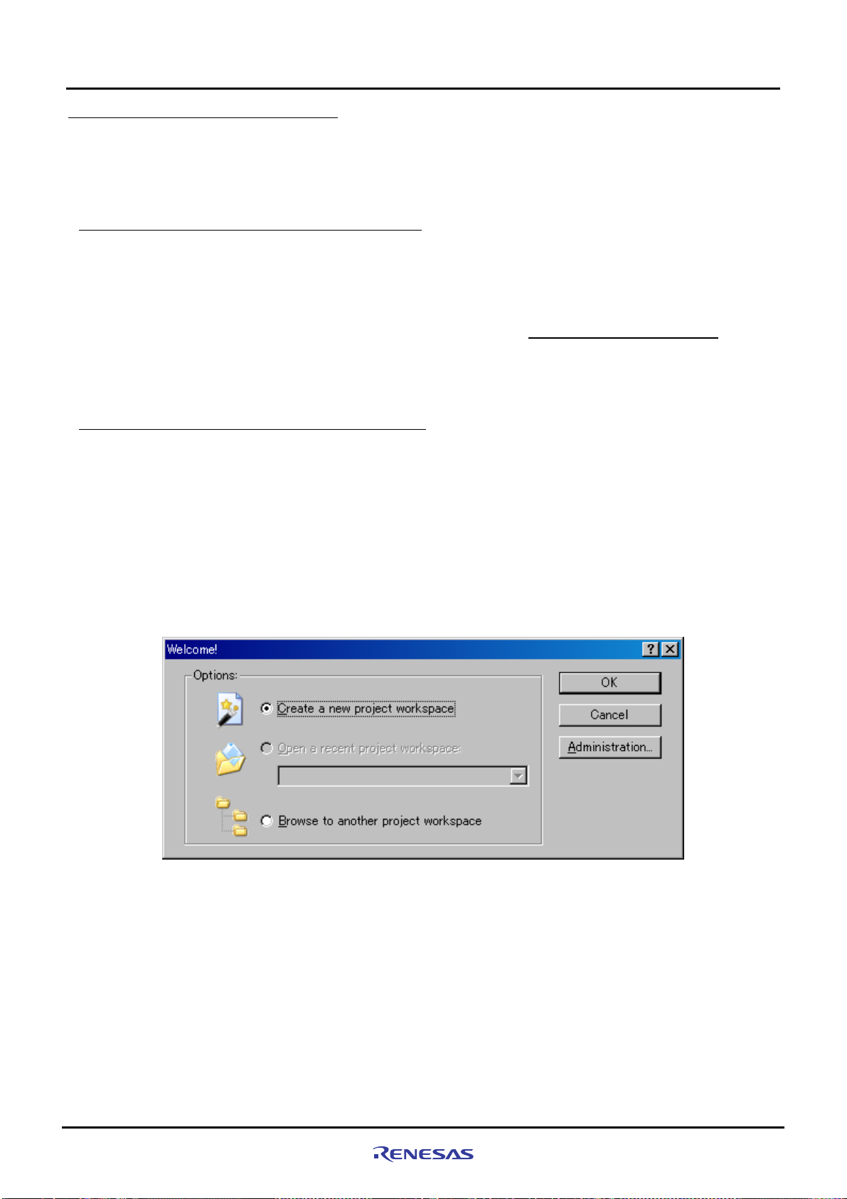
(4) [Welcome] dialog box shown below will be displayed.
(5) In this dialog box, select the option “Create a New Project Workspace” and click “OK”.
C:¥WorkSpace¥sample_software"
Rev. 1.01 May 7, 2008
REJ1 1J0015-0101
Figure 5.1.1 Welcome Dialog Box
5-2
Page 59

5
(6) Project Generator will start.
Here, enter “test” for the workspace name. After checking the directory, CPU type and tool chain, click “OK”.
Creating and Running a New Project Workspace
5.1.2 Procedure for Creating a New Project Workspace
Figure 5.1.2 New Project Workspace Dialog Box
(7) Next, select a “CPU Series” and a “CPU Type” from [New Project-1/9-Select Target CPU] dialog box. Make selections
as follows; CPU Series: SH-2A-FPU, CPU Type: Other
Rev. 1.01 May 7, 2008
REJ1 1J0015-0101
Figure 5.1.3 New Project-1/9 Dialog Box
5-3
Page 60

5
(8) Specify the global options from [New Project--2/9] dialog box.
FPU: Single
Round: Zero
Creating and Running a New Project Workspace
5.1.2 Procedure for Creating a New Project Workspace
Figure 5.1.4 [New Project-2/9] Dialog Box
(9) Fill out [New Project-3/9] to [New Project-4/9] dialog boxes. Select the check boxes as necessary. Leave default
settings intact here and simply click “Next”.
Rev. 1.01 May 7, 2008
REJ1 1J0015-0101
5-4
Page 61

5
(10) In [New Project-5/9] dialog box, set up a stack as follows;
Stack Pointer Address: H’FFF88000
Stack Size: H’400
*Stack size can be changed according to need.
Creating and Running a New Project Workspace
5.1.2 Procedure for Creating a New Project Workspace
Figure 5.1.5 New Project-5/9 Dialog Box
(11) In [New Project-6/9] dialog box, set up a vector.
Here, leave default settings intact (with the Vector Definition Files check box selected) and simply click “Next”.
Rev. 1.01 May 7, 2008
REJ1 1J0015-0101
Figure 5.1.6 New Project-6/9 Dialog Box
5-5
Page 62
Creating and Running a New Project Workspace
5
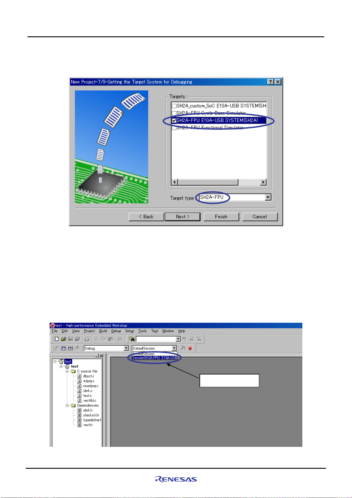
(12) In [New Project-7/9] dialog box, set up the target as below. Firstly, select the Target type and then, select the Targets.
Target type: SH2A-FPU
Targets: SH2A-FPU E10A-USB SYSTEM(SH2A)
5.1.2 Procedure for Creating a New Project Workspace
Figure 5.1.7 New Project-7/9 Dialog Box
(13) Verify [New Project-8/9] and [New Project-9/9] dialog boxes and click “Finish”.
Quit the Project Generator following the instructions shown in the window.
The HEW will be activated, automatically generating standard source files for the SH-2A device group.
(14) After the HEW started up, connect the E10A-USB emulator.
The E10A-USB emulator can be connected simply by switching to the session file for the E10A-USB emulator.
Note: The dialog box which confirms the change of session is displayed. Click “YES”.
Select the session
Rev. 1.01 May 7, 2008
REJ1 1J0015-0101
Figure 5.1.8 E10A-USB Emulator Connection Setup Screen
5-6
Page 63
5
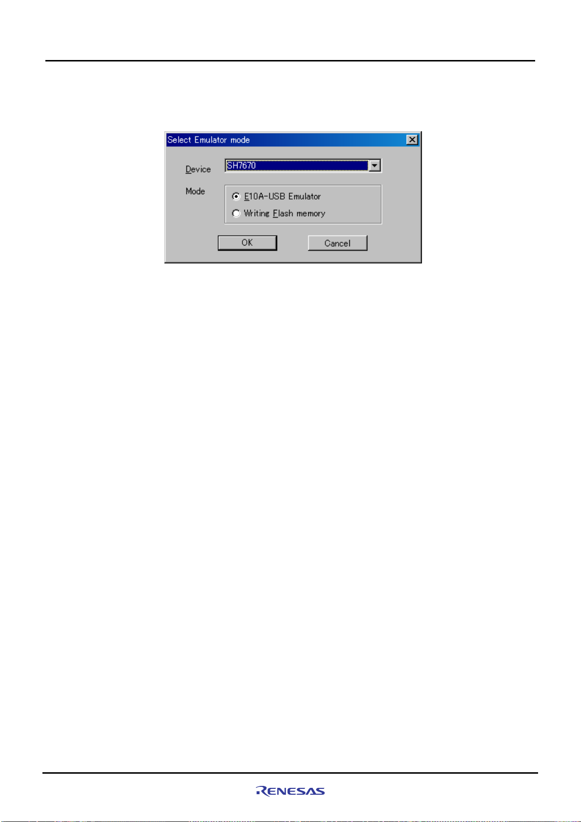
(15) [Select Emulator mode] dialog box shown below will be displayed.
For details on how to operate here, refer to paragraphs ”4.1.2 SH7670 CPU board and E10A-USB Startup Procedure
(HEW Startup)”
Figure 5.1.9 Select Emulator Mode Dialog Box
(16) Execute build processing.
Choose Build from the Build menu to execute build processing.
After the E10A-USB emulator has been connected, execute build processing once without modifying the standard
source file. If a build error occurs here, the SuperH RISC engine C/C++ compiler may not have been installed
normally.
Creating and Running a New Project Workspace
5.2 Setting Up the Flash Memory Download
Rev. 1.01 May 7, 2008
REJ1 1J0015-0101
5-7
Page 64

Creating and Running a New Project Workspace
5
5.2 Setting Up the Flash Memory Download
5.2 Setting Up the Flash Memory Download
Next, the following shows how to set up the function for downloading load modules into the flash memory connected
external to the SH7670 CPU board.
Here, we use the flash memory download program stored in
"C:¥ WorkSpace¥Sample_software¥sh7670_sample¥fmtool_hs71.
For details about flash memory download settings, refer to the “SuperH Family E10A-USB Emulator User’s Manual.”
5.2.1 Setting Up the Flash Memory Download Function
Setting up the flash memory download function
From [Setup] menu Æ [Emulator] Æ [System…], select [Configuration] dialog box, and open [Loading flash memory]
page.
For “File Name” here, specify the flash memory download pro gram (fmtool_hs71.mot). The sample workspace is
assumed to have the flash memory download program stored in the directory indicated below.
" C:¥WorkSpace¥Sample_software¥sh7670_sample¥fmtool_hs71"
Set up “Loading flash memory”, “File name”, “Bus width of flash memory” and “Entry point” as shown in
and
Table5.2.1. Then click “OK”
Note: Loading Flash Memory is set to “Disable” in the default setting. Therefore, you need to
connect the E10A-USB emulator.
enable it whenever you
Figure 5.2.1
Select “Enable”
Specify the path to
the fmtool_71.mot file.
Set the bus width to 16 bits.
Set H'FFF80000
for the write module address.
Rev. 1.01 May 7, 2008
REJ1 1J0015-0101
Figure 5.2.1 Configuration
Dialog Box
5-8
Page 65
Creating and Running a New Project Workspace
5
Table5.2.1 Loading flash memory Setting
Loading flash memory Enable
Erasing flash memory Disable
File name C:¥WorkSpace¥Sample_software¥sh7670_sample¥fmtool_hs71¥ fmtool_hs71.mot
Bus width of flash memory 16-bit
Flash memory erasing time All erasing module address Writing module address H'FFF80000
Access size 1 or 2
5.2.2 Specifying the Command Batch File Before Downloading
Next, you need to run the script file “fmtool_hs71.hdc” which has written the access timing and bus control signal
settings in the flash memory of the SH7670 CPU board before you download the modules.
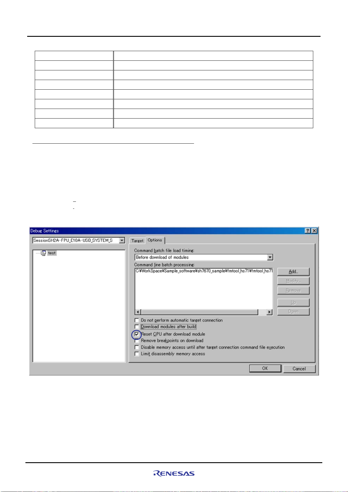
From the Debug menu, open the Debug Settings dialog box and select the Options tab.
Set up the items on this tab as shown below.
• Command
• Command
batch file load timing: Before download of modules
line batch processing:
5.2.2 Specifying the Command Batch File Before Downloading
"¥WorkSpace¥Sample_software¥sh7670_sample¥fmtool _hs71¥ fmtool_hs71.hdc "
Figure 5.2.2 Debug Settings Dialog Box
Note: With default settings, “Download modules after build” is selected. So deselect this check box, and then
select “Reset CPU after download module”, as shown above.
Rev. 1.01 May 7, 2008
REJ1 1J0015-0101
5-9
Page 66

Creating and Running a New Project Workspace
5
5.2.3 Activating the Command Line Window
Choose Command Line from the View menu and open the Command Line window.
When downloading the load modules, activate the Command Line window to check whether the script file is running.
Note: Unless the script file is running, you cannot download the load modules into the flash memory. So be sure to
check this.
5.2.3 Activating the Command Line Window
5.3 Adding/Modifying Hardware Setup Files
For the software to be run on the SH7670 CPU board, the hardware dependent part of the SH7670 CPU board must
be set up.
Here, the hardware dependent part of the SH7670 CPU board is added or modified for the standard source files that
were automatically generated when you created a new project. The procedure for adding/modif ying hardware setup
files is described below.
The setting of the hardware dependent part indicat es the settings of external memory (flash memory, SDRAM)
access timing, the operating clock and the cache memory.
5.3.1 Copying Hardware Setup Files
Copy “HardwareSetup” directory from the CD-ROM into the directory for the new project workspace
"C:¥WorkSpace¥test" that you created previously.
The explanation given below assumes that the hardware setup files are stored in
"
C:¥WorkSpace¥test¥HardwareSetup" directory.
5.3.2
Removing the Standard Source Files
(1) Select [Project Æ Remove Files...].
Rev. 1.01 May 7, 2008
REJ1 1J0015-0101
Figure 5.3.1 Setting Up to Removing Files (1)
5-10
Page 67

5
Creating and Running a New Project Workspace
5.3.3 Adding Hardware Setup Files
(2) From [Remove Project Files] dialog box, select the file of "dbsct.c", "intprg.c", "resetprg.c", "sbrk.c", and "vecttbl.c".
Then, click “Remove”.
5.3.3 Adding Hardware Setup Files
(1) Select [Project Æ Add Files...].
Figure 5.3.2 Setting Up to Removing Files (2)
Rev. 1.01 May 7, 2008
REJ1 1J0015-0101
Figure 5.3.3 Setting Up to Add Files (1)
5-1 1
Page 68

5
Creating and Running a New Project Workspace
5.3.3 Adding Hardware Setup Files
(2) From the "C:¥WorkSpace¥test¥HardwareSetup" directory to which you copied hard ware setup files, add the fil es
listed below.
Files to add : "bsc_cs0c.c", "bscsdram.c", "cache.c”, ”cpg.c", "dbsct.c", "hwsetup.c", "intprg.c", “lowsrc.c”,
"resetprg.c", “sbrk.c”, “siochar.c”, “siorw.c”, "vecttbl.c"
(Select the Relative Path check box)
Look in:
File name:
Select the
Relative
Path check
(3) Check to see that the files have been added as shown below.
Files of type:
Figure 5.3.4 Setting Up to Add Files (2)
Rev. 1.01 May 7, 2008
REJ1 1J0015-0101
Figure 5.3.5 Setting Up to Add Files (3)
5-12
Page 69
Creating and Running a New Project Workspace
5
5.3.4 Setting Compiler Options
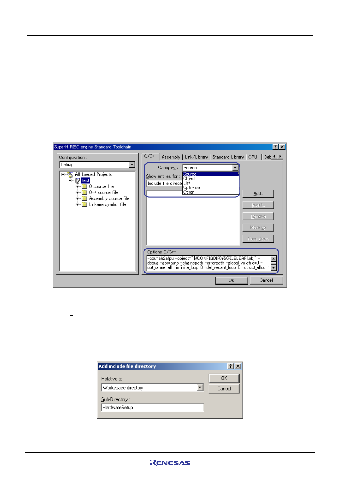
From the Build menu, open [SuperH RISC engine Standard Toolchain] dialog box and open [C/C++] tab. On this tab,
set “Category”, “Show entries for” and “Options C/C++” as necessary.
For details on how to set “Option C/C++”, refer to the manuals for SuperH RISC engine C/C++ compiler, assembler
and optimization linkage editor.
In the installation described here, because the include files for the hardware dependent part of the SH7670 CPU
board are stored in a separate directory other than the default proj ect directory, you ne ed to set an additional relative
path to the include file directory.
• Default project directory:
• Directory in which the include files are stored:
The following shows how to set a relative path to the include file directory.
"C:¥WorkSpace¥test¥test"
"C:¥WorkSpace¥test¥HardwareSetup"
5.3.4 Setting Compiler Options
Figure 5.3.6 Compiler Option Setup Window
(1) Open “C/C++” tab of [SuperH RISC engine Standard Toolchain] dialog box, set up the following, and click the
Add...”.
“
• Categor
Show entries for: Include file directory
•
(2) Open [Add include file directory] dialog box, make selections as shown below, and press “OK”.
• Relative to: Select “Workspace directory” from the dropdown list.
• Sub-directory: Enter “HardwareSetup” in the text box.
y: Source
Figure 5.3.7 Add Include File Directory Dialog Box
Rev. 1.01 May 7, 2008
REJ1 1J0015-0101
5-13
Page 70

Creating and Running a New Project Workspace
5
5.3.5 Setting Linker Options
Open the Build menu, open the dialog box [SuperH RISC engine Stand ard Toolchain ], and select “Link/Library” tab.
Set ”Category”, “Show entries for”, and “Option Link/Library” appropriately as necessary.
For details on how to set optimization linker options, refer to the user’s manuals for SuperH RISC engine C/C++
compiler, assembler and optimization linkage editor.
Here, the following describes how to change section settings.
5.3.5 Setting Linker Options
Figure 5.3.8 Linker Option Setup Window
Rev. 1.01 May 7, 2008
REJ1 1J0015-0101
5-14
Page 71

Creating and Running a New Project Workspace
5
(a) Section setting example for the case that a cache memory setup function is used
To use the io_init_cache function (that sets cache memory), the section for it must be loc ated in the non-cacheabl e
area of CS0. The following shows how to set up the section to the non-cacheable area of CS0.
For the details about cache memory, refer to the chapters of cache and BSC in SH7670 group hardware manual.
(1) From the Build menu, open [SuperH RISC engine Standard Toolchain] dialog box and then the Link/Library tab.
On this tab, select the following and then click “
• Categor
• Show entries for: Section
y: Section
Edit“.
5.3.5 Setting Linker Options
Figure 5.3.9 Section Settings (1)
(2) [Section] dialog box shown below will be displayed. In this dialog bo x, click “Add”.
Figure 5.3.10 Section Settings(2)
Rev. 1.01 May 7, 2008
REJ1 1J0015-0101
5-15
Page 72
5
Creating and Running a New Project Workspace
5.3.5 Setting Linker Options
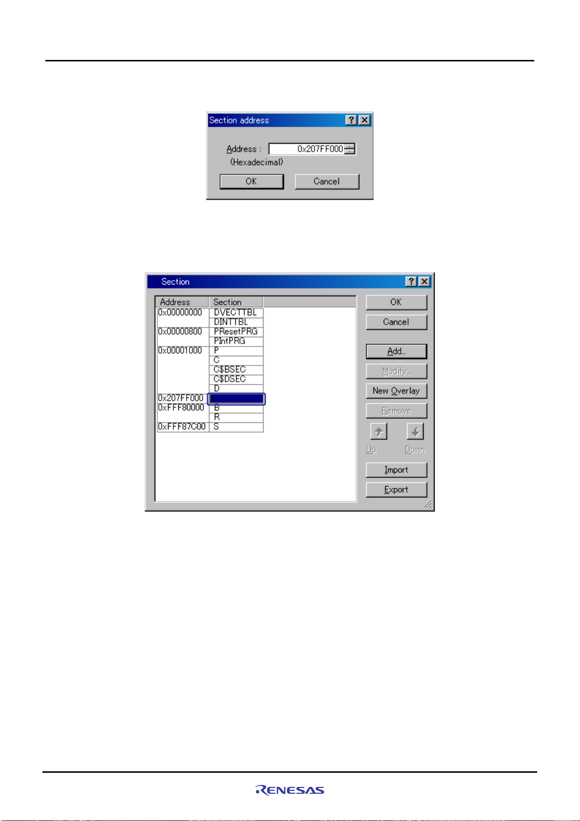
(3) [Section address] dialog box shown below will be displayed. In this dialog box, enter “0x207FF000” for the
Address as shown in
Figure 5.3.11, and press “OK”.
Figure 5.3.11 Section Settings (3)
(4) The section address will be added and it returns to [Section] dialog box. Choose a blank section as shown in
Figure 5.3.12, and click “Add”.
Rev. 1.01 May 7, 2008
REJ1 1J0015-0101
Figure 5.3.12 Section Settings (4)
5-16
Page 73

5
Creating and Running a New Project Workspace
5.3.5 Setting Linker Options
(5) [Add section] dialog box shown below will be displayed. Enter “PCACHE” for “Section name” as shown in
Figure 5.3.13, and press “OK”.
The “CACHE” section is defined in the “cache.c” source file. The first character “P” indicates a P section.
Set in the
non-cacheable
area of CS0
Figure 5.3.13 Section Settings (5)
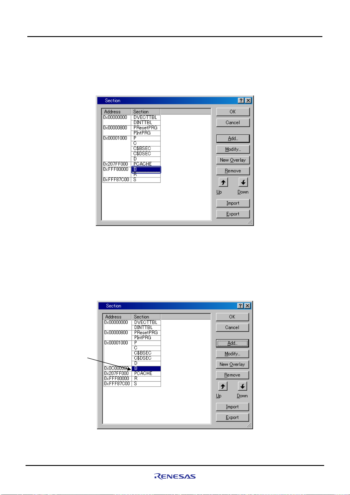
(6) The section name will be added, and it returns to [Section] dialog box. Confirm if the section has been set as
shown in
It returns to the SuperH RISC engine Standard Toolchain dialog box, so press “OK” to finish your settings
Figure 5.3.14, and press “OK”.
Rev. 1.01 May 7, 2008
REJ1 1J0015-0101
Figure 5.3.14 Section Settings (6)
5-17
Page 74
5
Creating and Running a New Project Workspace
5.3.5 Setting Linker Options
(b) Section modifications example for the case that a B section is changed to the SDRAM area
The following shows the section modification example for changing the location of a B section to the SD RAM area.
For a detailed procedure for section setting, refer to paragraph (a) described previously.
(1) In [Section] dialog box, select “B” section as shown in
Figure 5.3.15, and click “Remove”.
(2) In [Section] dialog box, set the B section in the SDRAM area as shown in
Example: Adding a section to the SDRAM
Note: For details about the SDRAM area in the SH7670 CPU board, refer to Section 1.7, “SH7670 Memor y
Setting the B section
in the SDRAM area
Figure 5.3.15 Section Change (1)
Figure 5.3.16.
• Address: 0x0C000000
• Section: B
Mapping,” in the SH7670 CPU board User’s Manual.
Rev. 1.01 May 7, 2008
REJ1 1J0015-0101
Figure 5.3.16 Section Change (2)
5-18
Page 75
5
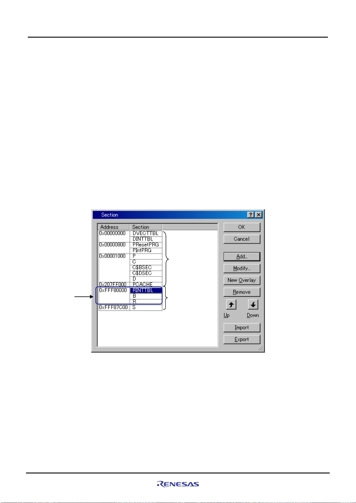
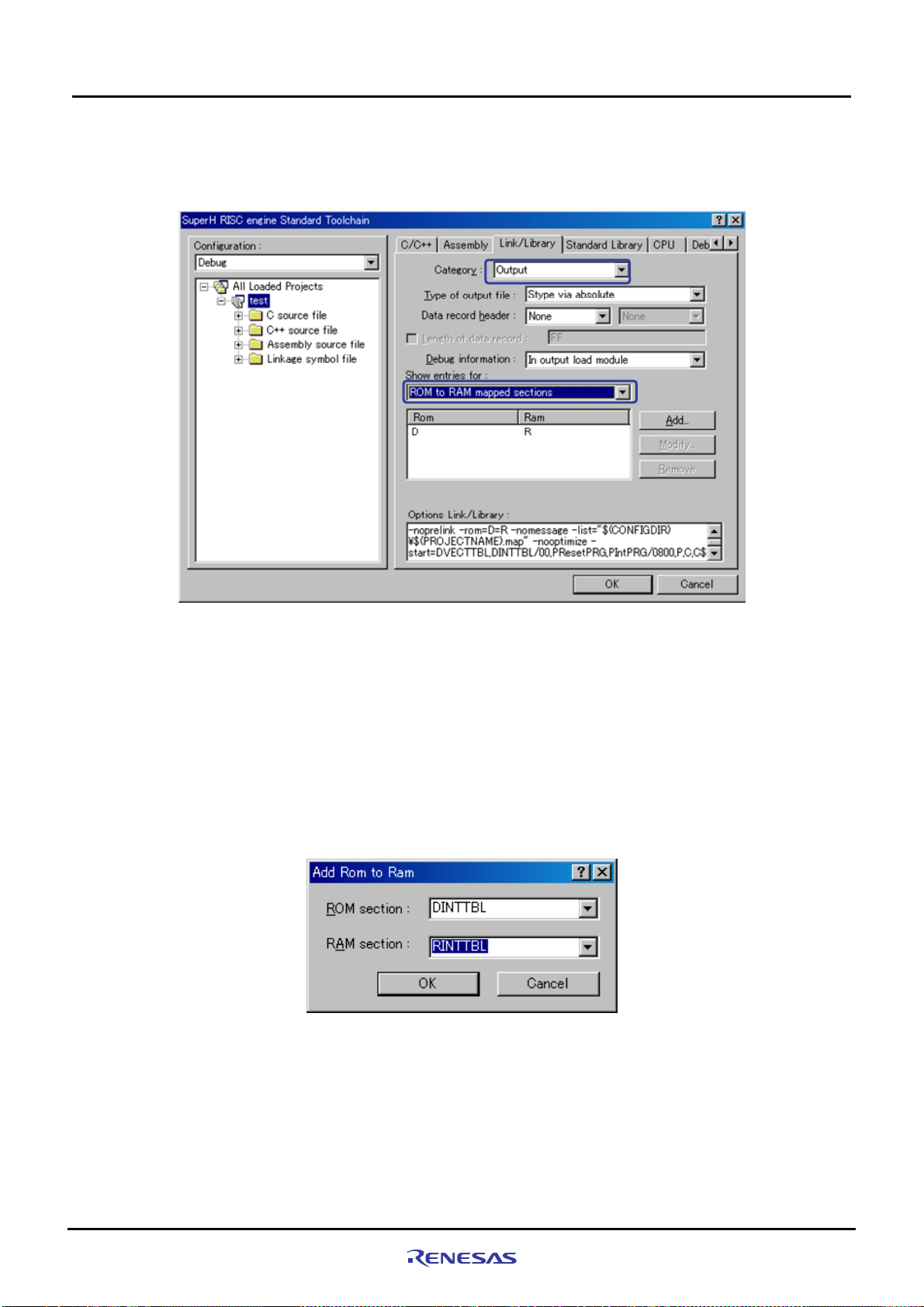
(c) Setting example for section in case for forwarding vector table section DINTTBL to on- ch ip RAM
Interrupt response speed can be sped up by forwarding vector table to on-chip RAM, and using register bank.
Forwarding vector table sets the vector table section on ROM as DINTT BL, and sets the section on RAM for the
forwarding destination as RINTTBL with "dbsct.c" added by 5.3.3.
<Section definition for vector table>
• Section name of vector table (ROM section): DINTTBL
• Section name of forwarding destination (RAM section): RINTTBL
The following shows the section setting procedure to modify the DINTTBL section from ROM to on-chip RAM
in the sample program.
(1) Set the RINTTBL section to on-chip RAM area in [Section] dialog box as shown in
<Example for adding section to on-chip RAM area>
“Address”: 0xFFF80000
“Section”: RINTTBL
Note: When the address above is set, the vector base register of CPU should be set. In the sample software,
the vector base register should be set inside the reset exception handling in the resetprg.c file.
Creating and Running a New Project Workspace
5.3.5 Setting Linker Options
Figure 5.3.17.
Change RINTTBL,
B, and R sections to
0xFFF80000 address
ROM area
RAM area
Figure 5.3.17 Section Change (1)
Rev. 1.01 May 7, 2008
REJ1 1J0015-0101
5-19
Page 76
5
Creating and Running a New Project Workspace
5.3.5 Setting Linker Options
(2) Open [Link/Library] tab and select the below, and click “Add”.
• Category : Output
• Show entries for : ROM to RAM mapped sections
Figure 5.3.18 Section Change (2)
Note: In the sample software, the section initialization table should be set inside the reset exception
handling in the dbsct.c file.
(3) Select the items as below on [Add Rom to Ram] dialog box, and click "OK".
It returns to [SuperH RISC engine Standard Toolchain] dialog box, and click "OK" to finish your setting.
• ROM section : DINTTBL
• RAM section : RINTTBL
Figure 5.3.19 Section Change (3)
Rev. 1.01 May 7, 2008
REJ1 1J0015-0101
5-20
Page 77

Creating and Running a New Project Workspace
5
5.3.6 Writing the Main Function (Operation Confirmation)
In the main function (test.c source file), write a program to turn on the LED (LED7 on the SH7670 CPU board lights up).
• Open the source file C:¥WorkSpace¥test¥test¥test.c with an editor, etc.
• Write the program that is shown below to turn on the LED.
Omitted
11: #include "iodefine.h"
12:
13: void main(void)
14: {
15: /* ==== Port setting ==== */
16: PORT.PCCRH1.BIT.PC20MD = 0;
17: PORT.PCDRH.BIT.PC20DR = 0;
18:
19: /* ====Port output (LED lights up) ==== */
20: PORT.PCIORH.BIT.PC20IOR = 1;
21: }
22:
Note: In this example, the value is set to the port C data register H (PCDRH) by the bit operation instruction. Since the
bit operation instruction performs the read modify write access, the port input level read for the unspe cified bit is
written in the port data register. As a result, please note that the unintended value might be set. In the other ports
(1) Creating a new load module
5.3.6 Writing the Main Function (Operation Confirmation)
Choose Build from the Build menu to execute build processing.
Note: Because the C section is not used, the following warning message will be displayed. It does not present
any problem.
(2) Creation of new test.abs
If a new load module (test.abs) has been created, it means that you’ve finished adding/modifying hardware setup
files successfully.
(3) Running the program
Try running the program after downloading the load module. (LED7 on the SH7670 CPU board lights up)
<Warning message>
L1100(W)Cannot find “C” specified in option “start”
Phase OptLinker finished
Build Finished
0 Errors,1 Warning
Rev. 1.01 May 7, 2008
REJ1 1J0015-0101
5-21
Page 78

5
Creating and Running a New Project Workspace
5.3.6 Writing the Main Function (Operation Confirmation)
*This page is blank*
Rev. 1.01 May 7, 2008
REJ1 1J0015-0101
5-22
Page 79

Revision History SH7670 CPU Board Installation Manual
Rev. Date of Issue Content of Revision
Page Points
1.00 Jan 9.08 - First edition issued.
1.01 May 7.08 - Revision history page location was changed.
Colophon was changed from ©2007 to ©2008.
Page 80

Page 81

SH7670 CPU Board
M3A-HS71
Installation Manual
Publication
Date
May 7, 2008 Rev. 1.01
Published by Renesas T echnology Corp.
Renesas Solutions Corp.
© 2008. Renesas Technology Corp., All rights reserved. Printed in Japan.
Page 82

SH7670 CPU Board
M3A-HS71
Installation Manual
1753, Shimonumabe, Nakahara-ku, Kawasaki-shi, Kanagawa 211-8668 Japan
REJ11J0015-0101
 Loading...