

Page 1
0300
REJ10B0224-
32176
Group
Starter Kit User’s Manual
M3A-2152
All information contained in these materials, including products and product specifications,
represents information on the product at the time of publication and is subject to change by
Renesas Technology Corp. without notice. Please review the latest information published
by Renesas Technology Corp. through various means, including the Renesas Technology
Corp. website (http://www.renesas.com).
Rev.3.00
Revision Date: Jan. 19, 2007
Page 2

Notes regarding these materials
1. This document is provided for reference purposes only so that Renesas customers may select the appropriate
Renesas products for their use. Renesas neither makes warranties or representations with respect to the
accuracy or completeness of the information contained in this document nor grants any license to any
intellectual property rights or any other rights of Renesas or any third party with respect to the information in
this document.
2. Renesas shall have no liability for damages or infringement of any intellectual property or other rights arising
out of the use of any information in this document, including, but not limited to, product data, diagrams, charts,
programs, algorithms, and application circuit examples.
3. You should not use the products or the technology described in this document for the purpose of military
applications such as the development of weapons of mass destruction or for the purpose of any other military
use. When exporting the products or technology described herein, you should follow the applicable export
control laws and regulations, and procedures required by such laws and regulations.
4. All information included in this document such as product data, diagrams, charts, programs, algorithms, and
application circuit examples, is current as of the date this document is issued. Such information, however, is
subject to change without any prior notice. Before purchasing or using any Renesas products listed in this
document, please confirm the latest product information with a Renesas sales office. Also, please pay regular
and careful attention to additional and different information to be disclosed by Renesas such as that disclosed
through our website. (http://www.renesas.com )
5. Renesas has used reasonable care in compiling the information included in this document, but Renesas
assumes no liability whatsoever for any damages incurred as a result of errors or omissions in the information
included in this document.
6. When using or otherwise relying on the information in this document, you should evaluate the information in
light of the total system before deciding about the applicability of such information to the intended application.
Renesas makes no representations, warranties or guaranties regarding the suitability of its products for any
particular application and specifically disclaims any liability arising out of the application and use of the
information in this document or Renesas products.
7. With the exception of products specified by Renesas as suitable for automobile applications, Renesas
products are not designed, manufactured or tested for applications or otherwise in systems the failure or
malfunction of which may cause a direct threat to human life or create a risk of human injury or which require
especially high quality and reliability such as safety systems, or equipment or systems for transportation and
traffic, healthcare, combustion control, aerospace and aeronautics, nuclear power, or undersea communication
transmission. If you are considering the use of our products for such purposes, please contact a Renesas
sales office beforehand. Renesas shall have no liability for damages arising out of the uses set forth above.
8. Notwithstanding the preceding paragraph, you should not use Renesas products for the purposes listed below:
(1) artificial life support devices or systems
(2) surgical implantations
(3) healthcare intervention (e.g., excision, administration of medication, etc.)
(4) any other purposes that pose a direct threat to human life
Renesas shall have no liability for damages arising out of the uses set forth in the above and purchasers who
elect to use Renesas products in any of the foregoing applications shall indemnify and hold harmless Renesas
Technology Corp., its affiliated companies and their officers, directors, and employees against any and all
damages arising out of such applications.
9. You should use the products described herein within the range specified by Renesas, especially with respect
to the maximum rating, operating supply voltage range, movement power voltage range, heat radiation
characteristics, installation and other product characteristics. Renesas shall have no liability for malfunctions or
damages arising out of the use of Renesas products beyond such specified ranges.
10. Although Renesas endeavors to improve the quality and reliability of its products, IC products have specific
characteristics such as the occurrence of failure at a certain rate and malfunctions under certain use
conditions. Please be sure to implement safety measures to guard against the possibility of physical injury, and
injury or damage caused by fire in the event of the failure of a Renesas product, such as safety design for
hardware and software including but not limited to redundancy, fire control and malfunction prevention,
appropriate treatment for aging degradation or any other applicable measures. Among others, since the
evaluation of microcomputer software alone is very difficult, please evaluate the safety of the final products or
system manufactured by you.
11. In case Renesas products listed in this document are detached from the products to which the Renesas
products are attached or affixed, the risk of accident such as swallowing by infants and small children is very
high. You should implement safety measures so that Renesas products may not be easily detached from your
products. Renesas shall have no liability for damages arising out of such detachment.
12. This document may not be reproduced or duplicated, in any form, in whole or in part, without prior written
approval from Renesas.
13. Please contact a Renesas sales office if you have any questions regarding the information contained in this
document, Renesas semiconductor products, or if you have any other inquiries.
Page 3

Precautions on Using The Product Described Herein
1. The product described herein should be used in combination with the parts included with the
starter kit. If the product is operated in combination with any other item, its operation cannot be
guaranteed. Nor will requests for help or suggestion be answered.
2. The product described herein was prepared for program development or evaluation purposes.
The product cannot be used for the mass production.
3. Renesas Technology Corporation and Renesas Solutions Corporation will not assume any
responsibility for the results of development no matter what systems may have been
developed by customers by using the product described herein.
4. Guarantee for the product described herein shall conform to stipulations under which
guarantee is provided for the starter kit.
5. The product described herein was prepared assuming it will be used in a laboratory or similar
environment for program development or evaluation purposes. It is not covered in the
electrical product safety laws, nor is it protected against electromagnetic hazards for use in
Japan or elsewhere.
For Inquiries About Product Contents or This Manual
Please contact:
Renesas Technology Corporation
at csc@renesas.com
* Microsoft, MS-DOS, Windows, and Windows NT are registered trademarks of Microsoft Corporation in the U.S. and other
countries.
* Adobe and Acrobat are registered trademarks of Adobe Systems Incorporated.
* All other brand names and product names are trademarks or registered trademarks of each proprietary company.
Page 4

Preface
Thank you very much for purchasing the 32176 Group Starter Kit, the M3A-2152G52A and
M3A-2152G52.
This manual describes how to set up the hardware and software products included with the
32176 Group Starter Kit and the precautions to be observed when using those products.
For details about the 32176 Group hardware and software products and development support
tools, refer to the user’s manuals and related documentation supplied with them.
Page 5

Contents
1. Overview........................................................................................................................1
1.1 Outline of the Starter Kit...................................................................................................................... 1
1.2 System Configuration.......................................................................................................................... 3
2. Contents of the Product Package..................................................................................4
2.1 Packaged Product Items..................................................................................................................... 4
2.2 Contents of CD-ROM.......................................................................................................................... 5
2.3 Other Necessary Items ....................................................................................................................... 5
3. Usage Precautions.........................................................................................................6
3.1 Guaranteed Scope of the Starter Kit................................................................................................... 6
3.2 Regarding About System Power-on Sequence when Connected to the Emulator............................. 6
3.2.1 M3A-2152G52A in Use.................................................................................................................. 6
3.2.2 M3A-2152G52 in Use....................................................................................................................6
3.3 About M32100T-EZ-E for M3A-2152G52A......................................................................................... 7
3.4 About M3T-CC32R.............................................................................................................................. 7
3.5 About M3T-PD32RM........................................................................................................................... 8
3.5.1 Operating Manuals ........................................................................................................................ 8
3.5.2 About Break Operation..................................................................................................................8
3.5.3 About Security Code Check Function............................................................................................ 9
3.6 About Evaluation Board .................................................................................................................... 10
3.6.1 Contact failure of IC Socket......................................................................................................... 10
3.6.2 Cable Connection........................................................................................................................ 10
4. Starter Kit Usage Conditions........................................................................................11
4.1 Ambient Conditions............................................................................................................................11
4.2 Host PC Condition..............................................................................................................................11
4.3 Conditions for the Power Supply Used..............................................................................................1 1
5. Hardware Setup...........................................................................................................12
5.1 Hardware Setup when M3A-2152G52A in Use.................................................................................12
5.1.1 M32100T-EZ-E Power Supply and Settings................................................................................ 12
5.1.2 M3A-2152 Evaluation Board Power Supply and Settings........................................................... 13
5.1.3 Connecting M3A-2152 Evaluation Board and M32100T-EZ-E.................................................... 13
5.1.4 System Power-on Sequence when M3A-2152G52A in Use.......................................................13
5.2 Hardware Setup when M3A-2152G52 in Use................................................................................... 14
5.2.1 M3A-2195 Power Supply Connection and Settings .................................................................... 14
5.2.2 Connecting to Host PC................................................................................................................ 14
5.2.3 M3A-2152 Evaluation Board Power Supply and Settings........................................................... 15
5.2.4 Connecting M3A-2152 Evaluation Board and M3A-2195............................................................ 15
5.2.5 System Power-on Sequence when M3A-2152G52 in Use.......................................................... 15
5.3 Hardware Setup when the Evaluation Board by Itself in Use........................................................... 16
5.3.1 M3A-2152 Evaluation Board Power Supply and Settings........................................................... 16
5.3.2 M3A-2152 Power Supply............................................................................................................. 16
6. Software Setup ............................................................................................................17
6.1 M3T-PD32RM.................................................................................................................................... 17
6.1.1 Installing M3T-PD32RM............................................................................................................... 17
6.1.2 Starting M3T-PD32RM................................................................................................................. 18
6.1.3 Error Messages During M3T-PD32RM Startup........................................................................... 20
6.1.4 Terminating M3T-PD32RM..........................................................................................................20
6.2 M3S-KD32R...................................................................................................................... ................21
6.2.1 Installing M3S-KD32R ................................................................................................................. 21
6.2.2 Starting M3S-KD32R ................................................................................................................... 22
6.2.3 Error Messages during M3S-KD32R Startup...............................................................................24
6.2.4 Terminating M3S-KD32R.............................................................................................................24
CONTENTS-1
Page 6

6.3
6.4 Browsing Electronic Manuals............................................................................................................ 25
M3T-CC32R......................................................................................................................................25
6.3.1 Installing M3T-CC32R.................................................................................................................. 25
6.3.2 Verifying Whether M3T-CC32R is Installed Normally.................................................................. 25
Appendix 1 Contents of CD-ROM...................................................................................26
1. Contents of CD-ROM...................................................................................................26
1.1 Acrobat.............................................................................................................................................. 27
1.2 Tool.................................................................................................................................................... 28
1.3 Manual............................................................................................................................................... 31
1.4 Board Related Manual (Document) .................................................................................................. 32
1.5 Sample Program ............................................................................................................................... 37
Appendix 2 Part List........................................................................................................38
Appendix 3 M3A-2152G02 Product Standards...............................................................41
1. Overview......................................................................................................................42
1.1 Outline of the Product ....................................................................................................................... 42
1.2 External View .................................................................................................................................... 43
1.3 Block Diagram................................................................................................................................... 44
1.4 Specifications of the Evaluation Board.............................................................................................. 45
1.4.1 Electrical Characteristics ............................................................................................................. 45
1.4.2 Functional Characteristics ........................................................................................................... 45
2. Functional Specifications.............................................................................................46
2.1 Configuration of the Power Supply ................................................................................................... 46
2.2 FP Select Circuit................................................................................................................................ 47
2.3 MOD Select Circuit............................................................................................................................ 48
2.4 Serial I/O Interface............................................................................................................................ 49
2.5 Oscillator Circuit................................................................................................................................ 51
2.6 General-purpose Output Port LED Indicators................................................................................... 52
2.7 General-purpose Input Port Control Circuit....................................................................................... 53
2.8 Analog Port Input Control Circuit....................................................................................................... 54
2.9 CAN Interface.................................................................................................................................... 55
2.10 JT AG Peripheral Circuit..................................................................................................................... 57
3. Reference Data............................................................................................................58
3.1 Jumper and Test Pin Lists................................................................................................................. 58
3.1.1 Jumpers.......................................................................................................................................58
3.1.2 Test Pins......................................................................................................................................58
3.2 Extension Connectors CON1 and CON2.......................................................................................... 59
3.2.1 Pin Assignments of the Extension Connector CON1...................................................................59
3.2.2 Pin Assignments of the Extension Connector CON2...................................................................60
3.3 Modular Cord for CAN....................................................................................................................... 61
3.4 Connection Diagram ......................................................................................................................... 62
3.5 Part List.............................................................................................................................................69
3.6 Pattern Diagram................................................................................................................................ 74
3.7 Diagram of External Dimension ........................................................................................................ 80
3.8 Description of Board Silk...................................................................................................................82
CONTENTS-2
Page 7

32176 Group
Starter Kit User’s Manual M3A-2152
32176 Group
Starter Kit User’s Manual M3A-2152
1. Overview
1.1 Outline of the Starter Kit
The Starter Kit M3A-2152G52A and M3A-2152G52 are provided for the evaluation of the 32176
Group microcomputers.
The M3A-2152G52A Starter Kit consists of M3A-2152G02 (32176 Group Evaluation Board),
M32100T-EZ-E (Emulator for M32R: model limited version), M3T-PD32RM (Emulator Debugger for
M32100T-EZ-E), and M3T-CC32R (Cross Tool Kit for the M32R Family; trial version). This is an
evaluation kit designed specifically for evaluating your computer at the early stage of system
development as well as developing application software for the 32176 Group.
It is capable of reprogramming internal flash memory of the 32176 Group microcomputer as well as
controlling. Included M32100T-EZ-E and M3T-PD32RM enable fast reprogramming MCU’s internal
flash memory.
The M3A-2152G52 Starter Kit consists of M3A-2152G02, M3A-2195 (SDI Interface Board with
Housing), M3S-KD32R (Debugger for the Starter Kit), and M3T-CC32R. It has the same functions
as the M3A-2152G52A St arter Kit.
Included M3A-2195 and M3S-KD32R enable fast reprogramming MCU’s internal flash memory.
Note: The M3A-2152G52 has been discontinued since December 1, 2004.
The following explains each item that constitutes the kits.
(1) M3A-2152G02 (M3A-2152 Evaluation Board)
The M3A-2152G02 Evaluation Board contains one of the 32176 Group microcomputer of 32-bit
and single-chip RISC with a socket.
You can evaluate a microcomputer using the M32R core, internal memory, and peripheral I/O
functions with the M3A-2152 Evaluation Board.
(2) M3T-CC32R (Cross Tool Kit)
The M3T-CC32R Cross Tool Kit, designed for use in developing application programs for the
M32R Family microcomputers, has abundant functions suitable for developing embedded control
systems using the M32R Family microcomputers. Included in the Starter Kit is a trial version of
it whose useful period is limited.
(3) M32100T-EZ-E (Emulator for M32R)
The M32100T-EZ-E Emulator connects the host PC’s USB port and the M3A-2152 Evaluation
Board’s JTAG pin together, for controlling input/output between M3T-PD32RM and the
M3A-2152 Evaluation Boards.
(Reference)
M32100T-EZ-E in M3A-2152G52A is an emulator designed exclusively for 32176 Group
microcomputer, and cannot be used for M32R microcomputers except for 32176 Group.
In case that the M32100T-EZ-E is used for the product except for 32176 Group, the upgrade
program to M32100T-EZ-E compliant with M32R microcomputers is available. For more details,
refer to the attachment of M32R/ECU starter kit release notes.
REJ10B0224-0300/Rev.3.00 Jan. 2007 Page 1 of 82
Page 8

32176 Group
Starter Kit User’s Manual M3A-2152
(4) M3T-PD32RM (Emulator Debugger)
M3T-PD32RM, the debugger software for the Starter Kit, enables debugging the application
system from the host PC by controlling the microcomputer on the M3A-2152 Evaluation Board
which is connected to the host PC via the M32100T-EZ-E emulator. You can analyze the operation
of a program available in load module form by using the M3T-CC32R Cross Tool Kit described
earlier. This debugger provides a man-machine interactive debugging environment based on
mouse manipulation by using a multi-window, graphical user interface comprised of easy to use
menus and multiple debugger windows and dialog boxes.
(5) M3A-2195 (SDI Interface Board with Housing)
The M3A-2195 connects the host PC’s LPT parallel port and the M3A-2152 Evaluation Board’s
JTAG pin together, for controlling input/output between M3S-KD32R and the M3A-2152
Evaluation Board.
(6) M3S-KD32R (Emulator Debugger)
M3S-KD32R, the debugger software for the Starter Kit, enables debugging the application
system from the host PC by controlling the microcomputer on the M3A-2152 Evaluation Board
which is connected to the host PC via the M3A-2195 Interface Board. The function of
M3S-KD32R is same as one of M3T-PD32RM.
REJ10B0224-0300/Rev.3.00 Jan. 2007 Page 2 of 82
Page 9
32176 Group
Starter Kit User’s Manual M3A-2152
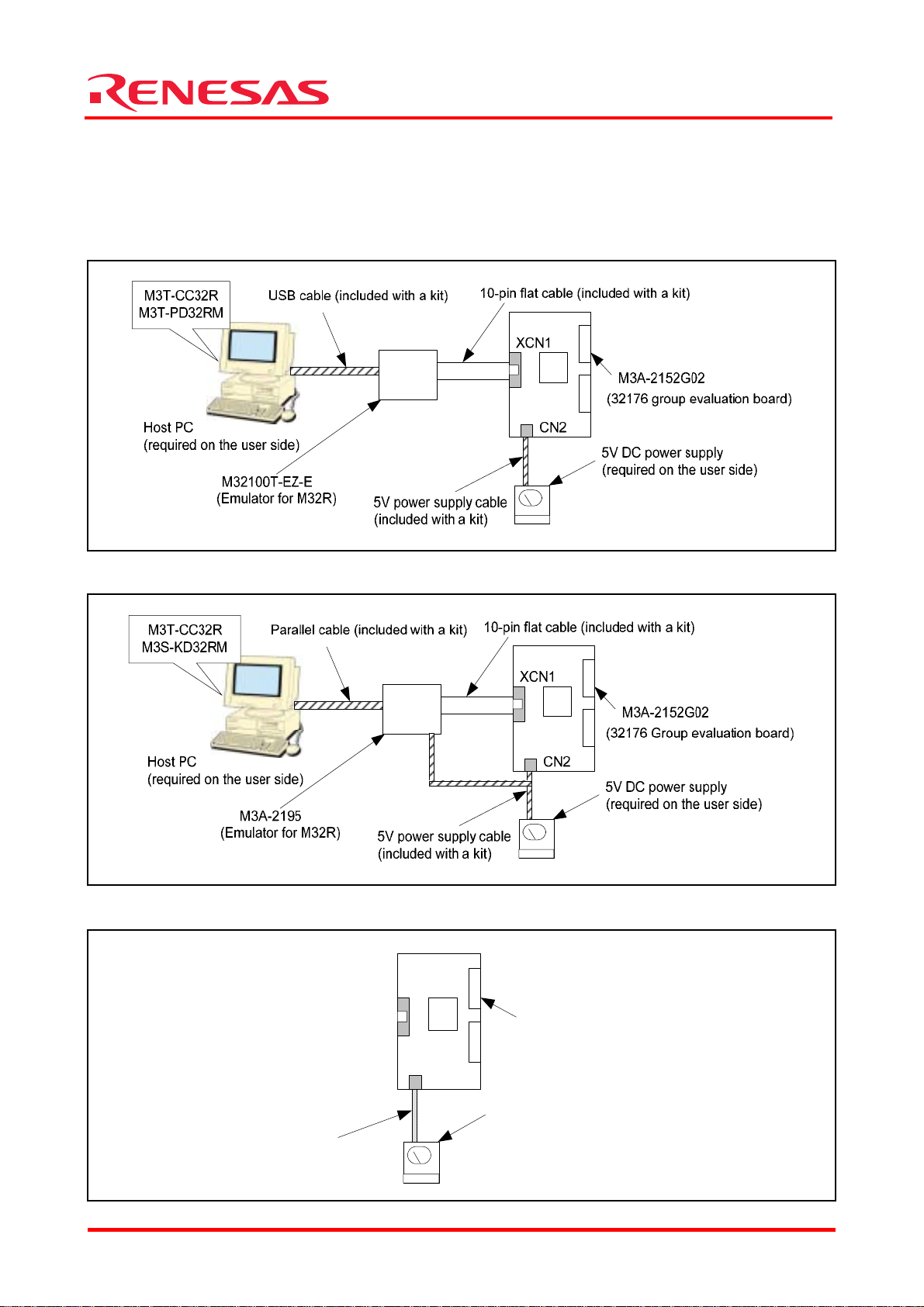
1.2 System Configuration
Figure 1.1, Figure 1.2 and Figure 1.3 below show system configurations of M3A-2152G52A
connected to an included emulator, system configurations of M3A-2152G52 connected to an
included emulator and M3A-2152G02 by itself, respectively.
Figure 1.1 System Configuration of M3A-2152G52A Connected to an Included Emulator
Figure 1.2 System Configuration of M3A-2152G52A Connected to an Included Emulator
Figure 1.3 System Configuration of M3A-2154G02A by Itself
5V power supply cable
(included with a kit)
XCN1
M3A-2152G02
(32176 Group evaluation board)
CN2
5V DC power supply
(required on the user side)
REJ10B0224-0300/Rev.3.00 Jan. 2007 Page 3 of 82
Page 10
32176 Group
Starter Kit User’s Manual M3A-2152
2. Contents of the Product Package
This chapter shows the contents of the Starter Kit product package. When unpacking, check to see
that all items are included with your package.
2.1 Packaged Product Items
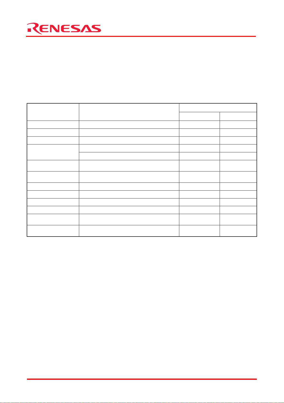
Table 2.1 shows the con tents of the Starter Kit product package.
Table 2.1 Packaged Contents of 32176 Group Starter Kit
Packaged product
name
M3A-2152G02 32176 Group Evaluation Board 1 pc 1 pc
M32100T-EZ-E Emulator for M32R 1 pc —
M3A-2195 Simple emulator probe — 1 pc
5V power supply
cable
12V power supply
cable
10-pin Flat cable
USB cable Connected M32100T-EZ-E and host PC 1 pc —
Parallel cable Connected M3A-2195 and host PC — 1 pc
CAN cable CAN cable 2 pc 2 pc
CD-ROM Contained documents and software 1 pc 1 pc
M32R/ECU Starter Kit
release note
IMPORTANT-READ
ME FIRST
Note: When you unpack the Starter Kit, check to see that none of the above package contents is damaged or missing. If
any item is damaged or not included, return the package to Renesas Technology Corporation through distributors.
It will be replaced with a new one.
Used for the M3A-2152 Evaluation Board 1 pc 1 pc
Used for the M3A-2195 — 1 pc
Used for the M3A-2195 — 1 pc
Connected the M3A-2152 Evaluation Board
and M32100T-EZ-E/M3A-2195
M3A-2152Gxx release notes 1 copy 1 copy
Written contract 1 copy 1 copy
Outline of product
M3A-2152G52A M3A-2152G52
1 pc 1 pc
Quantity
REJ10B0224-0300/Rev.3.00 Jan. 2007 Page 4 of 82
Page 11

32176 Group
Starter Kit User’s Manual M3A-2152
2.2 Contents of CD-ROM
The CD-ROM contains the software, manuals, various data sheets, and sample programs which are
needed for you to use the Starter Kit.
When using the technical contents of the CD-ROM such as product data, diagrams, and tables or
the programs and algorithms also included in the CD-ROM for your application, please be sure to
evaluate those technical contents, programs, and algorithms as the whole system, and not
individually as single items before you determine whether they are useful. Renesas Technology
Corporation will not assume any responsibility regarding the ir suita bility for your application.
The following shows directory configurations of data/manuals included in the CD-ROM.
For details, refer to Appendix 1.
Jpn/ Eng + Readme_j.txt/ Readme_e.txt : README file
+ AcrobatReader : Tool for read pdf file
+ Tool + : Software for the M32R Family
| + Cc32r : Cross Tool Kit for the M32R Family (Trial version)
| + Pd32rm : Debugger for the M32R Family
| + Kd32r : Debugger for the M32R Family
| + Ufla32r : Flash memory reprogramming kit for M32R/ECU by UART
| + Oldversion : Old version of Tools
|
+ Document + : Materials associated with boards
| + M3A-2114 : Materials associated with the 32170/32174/32171/32172/32173
| Evaluation board (M3A-2114)
| + M3A-2142 : Materials associated with the 32180/32182 Evaluation board
| (M3A-2142)
| + M3A-2152 : Materials associated with the 32176 Evaluation board
| (M3A-2152)
| + M3A-2154 : Materials associated with the 32185/32186/32192/32195/32196
| Evaluation board (M3A-2154)
| + M3A-2191 : Connector Pitch Converter for M3A-2114 Evaluation board
| and M32100T-EZ-E
| + M32100T-EZ-E : Materials associat ed with the Emulator for M32R
| + M3A-2145 : Manual for Flash memory reprogramming kit (Ufla32r)
| + Discontinued_model : Materials associated with the discontinued boards (M3A-2195)
|
+ Manual : M32R/ECU manuals, data sheets, M32R Family
| software manuals
+ SampleProgram : Application notes and listed object/source files
2.3 Other Necessary Items
Before the Starter Kit can be used, the following ite m s should separately be prepared by the user.
- Host PC (see Section 4.2 Host PC Condition)
- Power supply (see Section 4.3 Conditions for the Power Supply Used)
REJ10B0224-0300/Rev.3.00 Jan. 2007 Page 5 of 82
Page 12

32176 Group
Starter Kit User’s Manual M3A-2152
3. Usage Precautions
3.1 Guaranteed Scope of the Starter Kit
The Starter Kit was developed for users to trial the 32176 Group microcomputer specifications and
development environment. Therefore, the results arising from the use of the Starter Kit are not
guaranteed.
The M3A-2195 (SDI Interface Board with Housing) was developed for use with only the Starter Kit.
If the M3A-2195 is used with any other system, its operation cannot be guaranteed.
When developing/debugging a system product using one of the M32R Family microcomputers,
please be sure to use official developmen t to ols separately available as you debug.
The Starter Kit should be run on the designated type of host machine (IBM PC/AT compatibles).
This designated type of host machine, however, is just an anticipated operating environment for the
Starter Kit and does not mean that the Starter Kit operates properly on all relevant types of
machines in all relevant environments (e.g., device drivers and peripheral units).
3.2 Regarding About System Power-on Sequence when Connected to the Emulator
3.2.1 M3A-2152G52A in Use
- When turning on power, turn on M32100T-EZ-E first and then the M3A-2152 Evaluation
Board.
- When turning off power, turn off the M3A-2152 Evaluation Board first and then
M32100T-EZ-E.
- When turning on power again after turning off power, wait for 10 seconds.
- Power to M32100T-EZ-E can be fed from USB cable.
Note: Unless the Starter Kit is powered on this sequence, the kit may operate erratically or break down.
3.2.2 M3A-2152G52 in Use
- When turning on power, turn on M3A-2195 first and then the M3A-2152 Evaluation Board, or
simultaneously.
- When turning off power, turn off the M3A-2152 Evaluation Board first and then M3A-2195, or
simultaneously.
- When turning on power again after turning off power, wait for 2 seconds.
Note: Unless the Starter Kit is powered on this sequence, the kit may operate erratically or break down.
REJ10B0224-0300/Rev.3.00 Jan. 2007 Page 6 of 82
Page 13

32176 Group
Starter Kit User’s Manual M3A-2152
3.3 About M32100T-EZ-E for M3A-2152G52A
M32100T-EZ-E in M3A-2152G52A is an emulator designed exclusively for 32176 Group
microcomputer, and cannot be used for M32R microcomputers except for 32176 Group.
In case that the M32100T-EZ-E is used for the product except for 32176 Group, the upgrade
program to M32100T-EZ-E compliant with M32R microcomputers is available. For more details,
refer to the attachment of M32R/ECU starter kit release notes.
3.4 About M3T-CC32R
M3T-CC32R (M32R Family Cross Tool Kit) included with the Starter Kit is a trial version whose
useful period is limited.
This version becomes unusable four months after it is installed. Past this period, it cannot be used
even by reinstalling. If you wish to continue using M3T-CC32R, please purchase a production
version of M3T-CC32R separately from distributors.
REJ10B0224-0300/Rev.3.00 Jan. 2007 Page 7 of 82
Page 14

32176 Group
Starter Kit User’s Manual M3A-2152
3.5 About M3T-PD32RM
The following describes precautions to be observed when using M3T-PD32RM.
3.5.1 Operating Manuals
To use M3T-PD32RM of M3A-2152G52A, see the manuals shown below.
- M3T-PD32RM release notes
- PD32RM Help
To use M3S-KD32R of M3A-2152G52, see the manuals shown below.
- M3S-KD32R release notes
- PD32R Help
3.5.2 About Break Operation
M3T-PD32RM (or M3S-KD32R) uses the M32R core’s internal debug circuit (SDI) to realize break
functions. For this reason, the break functions of M3T-PD32RM (or M3S-KD32R) behave
differently from those in conventional emulators.
Furthermore, because M3T-PD32RM (or M3S-KD32R) does not have SDI trace pins as
corresponding hardware resources, the trace pin corresponding break functions available with
M3T-PD32R-compatible emulators are not supported.
The following explains the four types of breaks that can be executed with M3T-PD32RM (or
M3S-KD32R).
(1) Software break
Up to 64 software breakpoints can be set and executed in RAM areas accessible by the target
MCU. No software breakpoints can be set and executed in ROM areas such as the internal flash
memory.
(2) Pre-execution PC break
The M32R core’s internal debug circuit (SDI) allows setting breakpoints, at which to break the
program immediately before executing an instruction (at the address indicated by the program
counter).
For the M3A-2152G52A and M3A-2152G52 (32176 Group MCU), four such breakpoints can be
set.
(3) Post-execution PC break
The M32R core’s internal debug circuit (SDI) allows setting one breakpoint, at which to break the
program immediately after executing an instruction (at the address indicated by the program
counter).
(4) Chip break
The M32R core’s internal debug circuit (SDI) allows setting breakpoints, at which to break the
program when accessing memory for read/write.
For M3A-2152G52A and M3A-2152G52 (32176 Group MCU), two such breakpoints (level 2) can
be set.
* The differences between levels 1 and 2 are outlined below.
Level 1: Whether data which is maskable matches or not can be detected.
Level 2: Data is maskable and an address range can be specified for the target data.
REJ10B0224-0300/Rev.3.00 Jan. 2007 Page 8 of 82
Page 15
Starter Kit User’s Manual M3A-2152
(5) About hardware break
Debug functions of M3T-PD32RM (or M3S-KD32R) are realized by using the M32R core’s internal
debug circuit (SDI), and not by using the emulator’s hardware resources based on bus signals and
debug information from the MCU as in conventional emulators. The pre-execution PC break,
post-execution PC break, and chip break all uses this internal debug circuit (SDI).
Because the M3T-PD32RM (or M3S-KD32R) does not have trace pin information available as
hardware resources, the hardware break functions cannot be used that use the trace pins
implemented in the M3T-PD32R-compatible emulators.
Heed this point when referring to the PD32RM Help and PD32R Help.
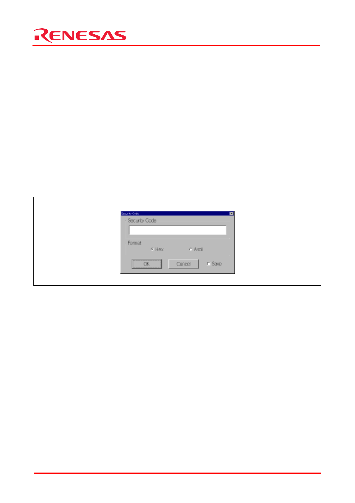
3.5.3 About Security Code Check Function
If the target microcomputer has security code stored in it, the dialog box shown in Figure 3.1
appears at M3T-PD32RM (or M3S-KD32R) startup. When this dialog box is displayed, enter the
appropriate security code. If the security code you’ve entered does not match the stored security
code, M3T-PD32RM (or M3S-KD32R) will not start unless the contents of the internal flash
memory are deleted.
Figure 3.1 Security Code Input Dialog Box
Be sure to enter the security code that you set when writin g to the flash memory.
Use the Format select button to choose the format of the security code you entered. Select the
Save check box, and the security code you entered is saved. From next time on, the security code
saved here is used to check matching with the stored security code when M3T- PD32RM (or
M3S-KD32R) starts.
32176 Group
REJ10B0224-0300/Rev.3.00 Jan. 2007 Page 9 of 82
Page 16
32176 Group
Starter Kit User’s Manual M3A-2152
3.6 About Evaluation Board
When the evaluation board does not start operation after supplied power, check the following
points.
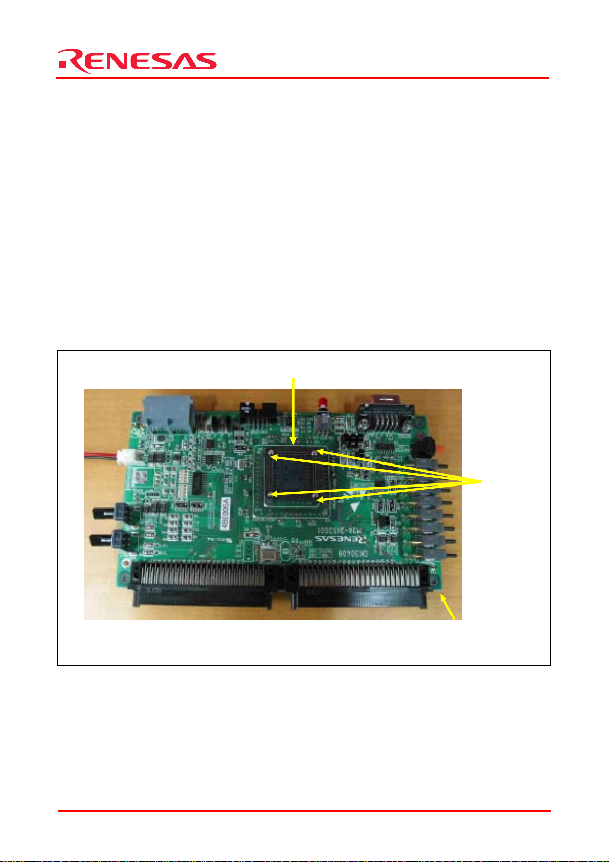
3.6.1 Contact failure of IC Socket
Oscillation or thermal expansion may cause a poor connection between microcomputers and IC
socket on the Evaluation Board. Follow the steps below.
- Screw down the top cover of IC socket with setscrews at four corners.
The tightening torque shall be 0.054 N.m.
Note that only one tight setscrew may cause a poor connection.
The IC socket included in the evaluation board uses NQPACK and HQPACK by TOKYO
ELETECH CORPORATION.
For more details, visit their website at http://www.tetc.co.jp/e_index.htm.
The following illustrates configuration of M3A-21 52G02 (32176 Group Evaluation Board).
Figure 3.2 M3A-2154G02A
IC socket (HQPACK)
Setscrews on
cover of
IC socket
32176 group evaluation
board M3A-2152G02
3.6.2 Cable Connection
- Make sure the cables are connecte d to the evaluation board firmly.
REJ10B0224-0300/Rev.3.00 Jan. 2007 Page 10 of 82
Page 17
32176 Group
Starter Kit User’s Manual M3A-2152
4. Starter Kit Usage Conditions
The following shows the conditions under which the Starter Kit can be used.
4.1 Ambient Conditions
Table 4.1 shows the amb ient cond itions under which the Starter Kit can be used.
Table 4.1 Operating Environment
Symbol Parameter Rated value Remarks
Operating ambient temperature when
Topr
connecting to emulator
Operating ambient temperature when
using evaluation board by itself
Storage ambient temperature for
Ts tr
emulator
Storage ambient temperature for
evaluation board
o
5
C to 35oC
o
0
C to 70oC
o
-10
C to 60oC
o
C to 70oC
0
No dewdrops allowed.
Corrosive gas environment not
allowed.
4.2 Host PC Condition
It is recommended that each software included with the Starter Kit be run on the host PC under
the OS listed in T able 4.2.
Table 4.2 Host PC Conditions
Starter Kit Type Name M3A-2152G52A M3A-2152G52
Host PC IBM PC/AT compatibles
CPU Pentium III 500MHz or higher CPU is recommended
Memory 192 Mbytes or more system memory is recommended
OS Windows 98, Me, 2000, XP Windows 98, Me, NT4.0, 2000
USB Port 1 port (required) —
LPT Port — 1 port (required)
4.3 Conditions for the Power Supply Used
Table 4.3 shows pow er su pply specifications required when using the Starter Kit.
Table 4.3 Power Supply Specifications
Symbol Power supply voltage Power supply current
VCC 4.75 V to 5.25 V 1A
GND 0V (reference voltage) —
REJ10B0224-0300/Rev.3.00 Jan. 2007 Page 11 of 82
Page 18
32176 Group
Starter Kit User’s Manual M3A-2152
5. Hardware Setup
This chapter describes how to set up the hardware components necessary to use the Starter Kit.
Table 5.1 an d Table 5.2 show how to set up the hardware components.
Table 5.1 Hardware Setup Procedure
Setup Procedure
When connected to the emulator
M3A-2152G52A M3A-2152G52 M3A-2152G52A/M3A-2152G52
Set the emulator 1st (Refer to 5.1.1) 1st (Refer to 5.2.1)—
Connect the host PC and emulator 2nd (Refer to 5.1.1) 2nd (Refer to 5.2.2)—
Set the evaluation board 3rd (Refer to 5.1.2) 3rd (Refer to 5.2.3) 1st (Refer to 5.3.1)
Connect the evaluation board and
emulator
4th (Refer to 5.1.3) 4th (Refer to 5.2.4)—
Turn on the emulator 5th (Refer to 5.1.4) 5th (Refer to 5.2.5)—
Turn on the evalution board 6th (Refer to 5.1.4) 6th (Refer to 5.2.5) 2nd (Refer to 5.3.2)
Table 5.2 Hardware Power Off Procedure
Setup Procedure When connected to the emulator
Turn off the evaluation board. 1st (Refer to 5.1.4) 1st (Refer to 5.3.2)
Turn off the emulator. 2nd (Refer to 5.1.4) —
When using the evaluation
board by itself
When using the evaluation
board by itself
5.1 Hardware Setup when M3A-2152G52A in Use
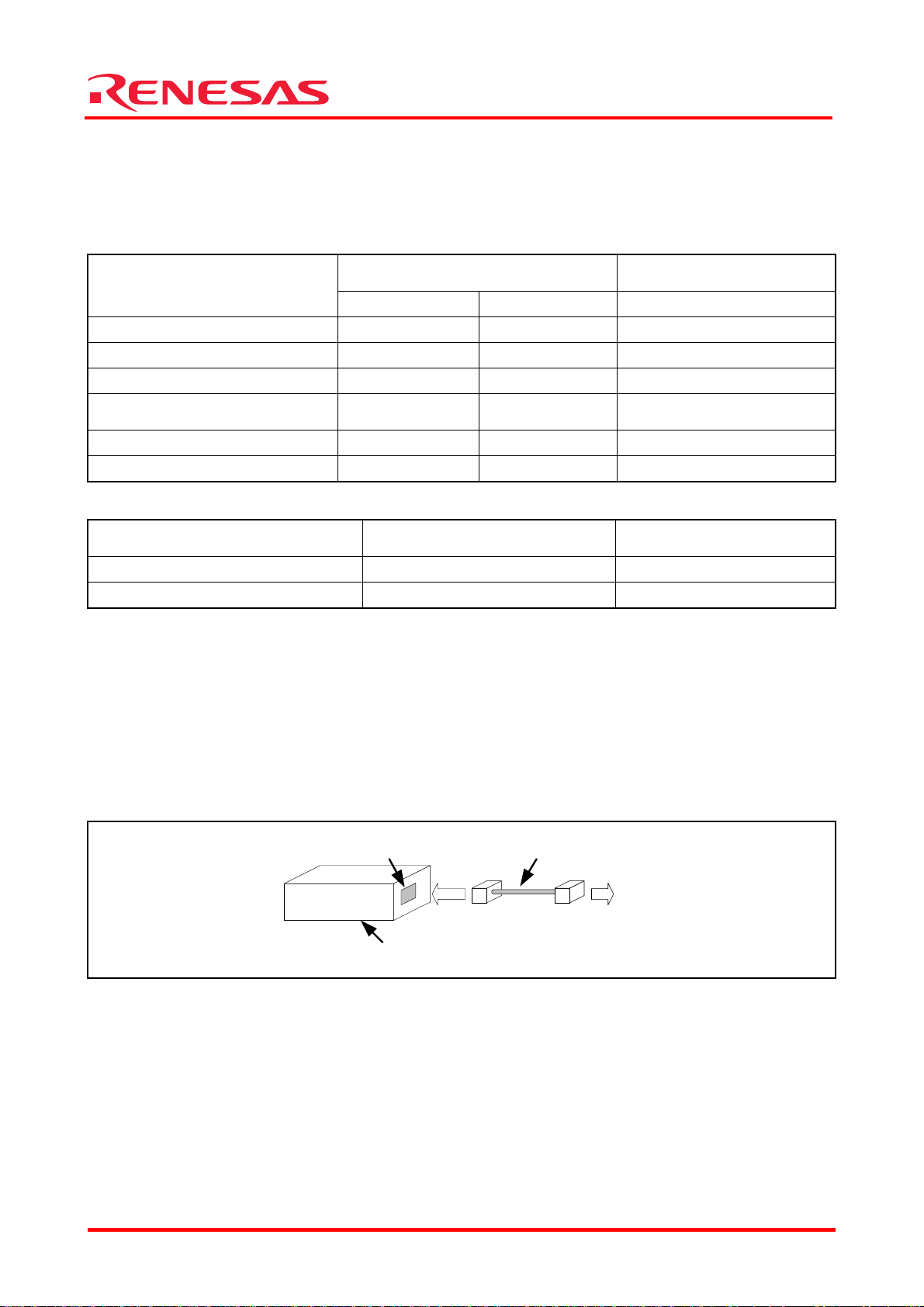
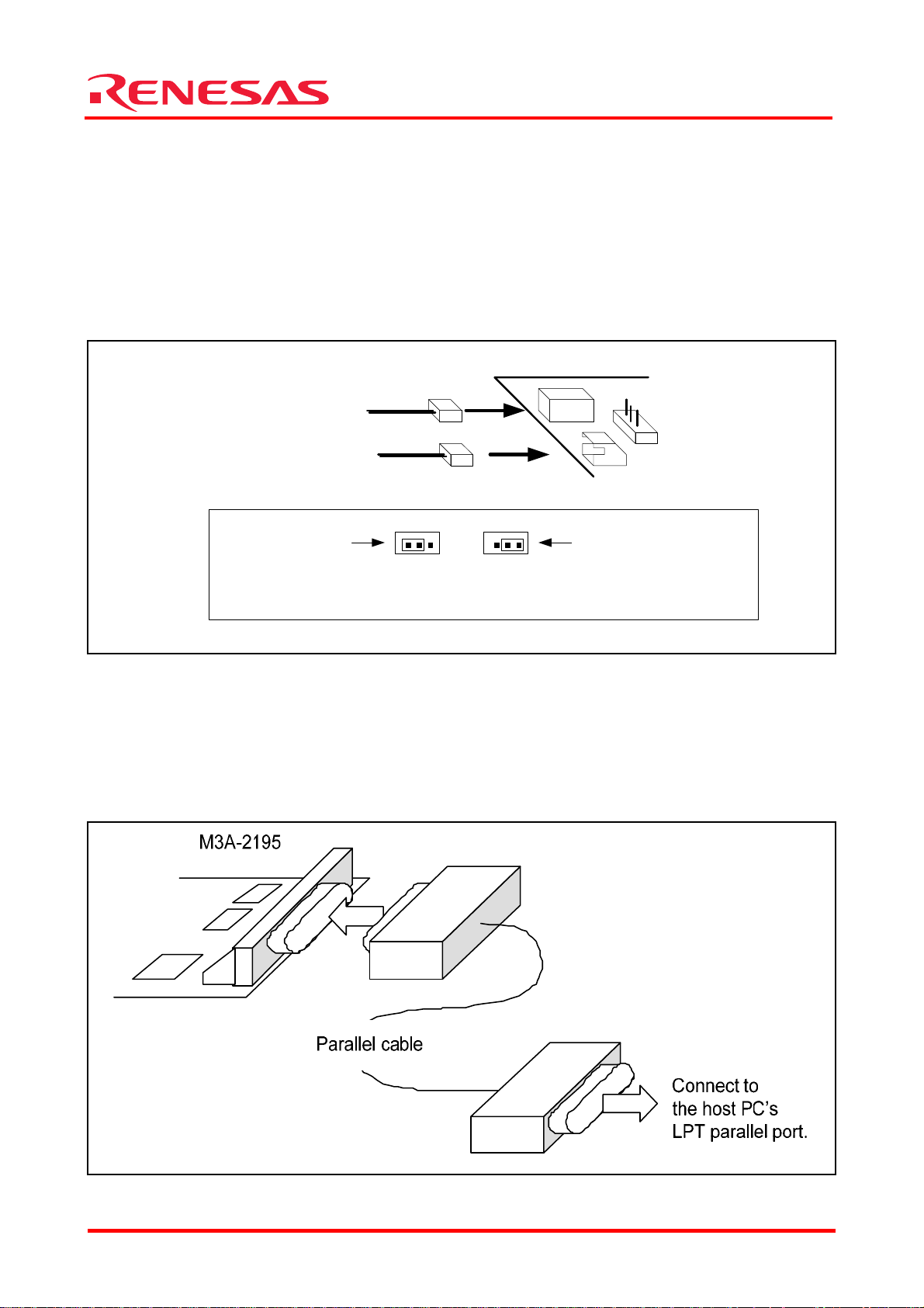
5.1.1 M32100T-EZ-E Power Supply and Settings
The following shows how to set M32100T-EZ-E.
For more details, refer to M32100T-EZ-E User’s Manual.
M32100T-EZ-E is supplied power from the host PC via USB cable, and it turns ON by connecting
included USB cable.
The Connecting M32100T-EZ-E and Host PC is shown in Figure 5.1
Figure 5.1 Connecting M32100T-EZ-E and Host PC
USB I/F
M32100T-EZ-E
USB cable
Connect to the host
PC’s USB port
REJ10B0224-0300/Rev.3.00 Jan. 2007 Page 12 of 82
Page 19
Starter Kit User’s Manual M3A-2152
5.1.2 M3A-2152 Evaluation Board Power Supply and Settings
The following shows how to set the M3A-2152 Evaluation Board.
Use a 5V DC power supply to feed power to the M3A-2152 Evaluation Board.
Use included 5V power supply cable to connect the 5V DC power supply and CN2 connector
included with the M3A-2152 Evaluation Board. The Connecting when Feeding Power to the
M3A-2152 Evaluation Board is shown in Figure 5.2.
Figure 5.2 Connecting when Feeding Power to the M3A-2152 Evaluation Board
Table 5.3 Jumper Settings before Shipmen
Jumper Name Jumper Settings Remarks
H1 Shorted between 1-2 Uses power from CN2 connector to AVCC power supply
M3A-2152 evaluation board
CN2
H1
4.75 - 5.25V DC power supply
32176 Group
Note: For detail about the power supply settings, refer to Appendix 3 M3A-2152G02 Product Standards
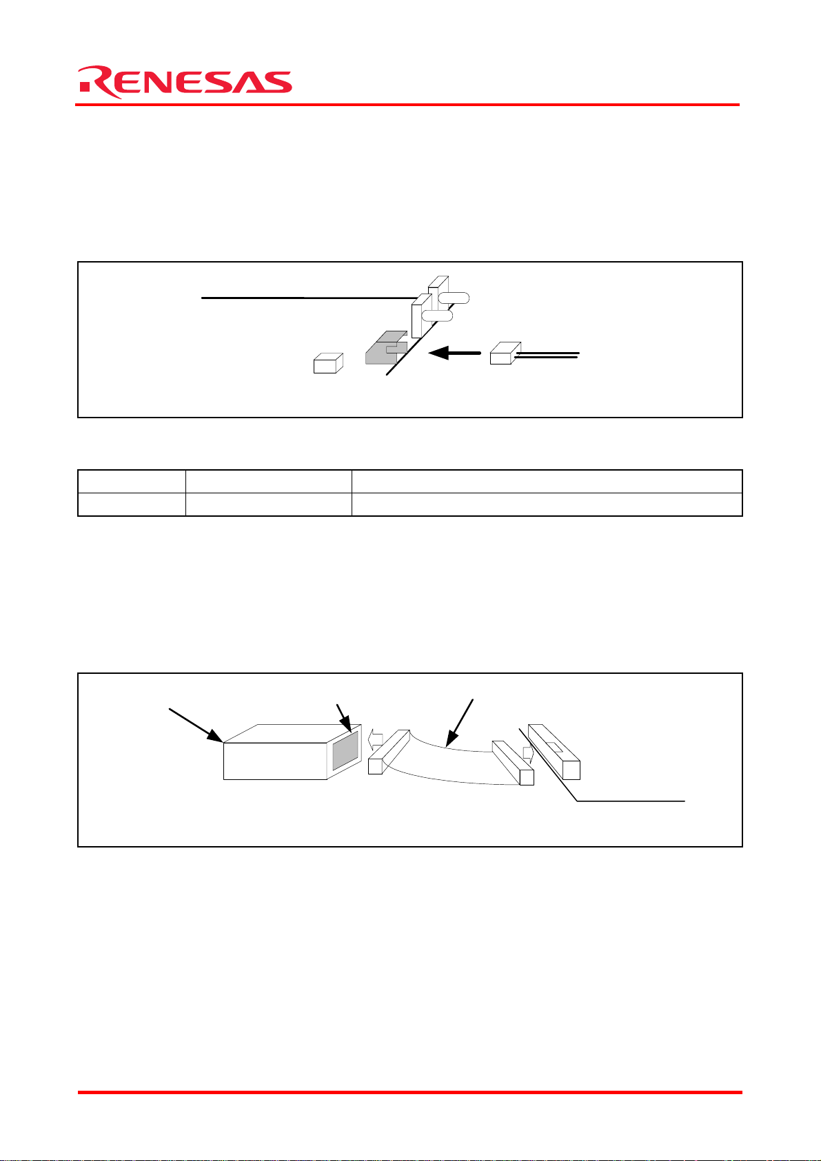
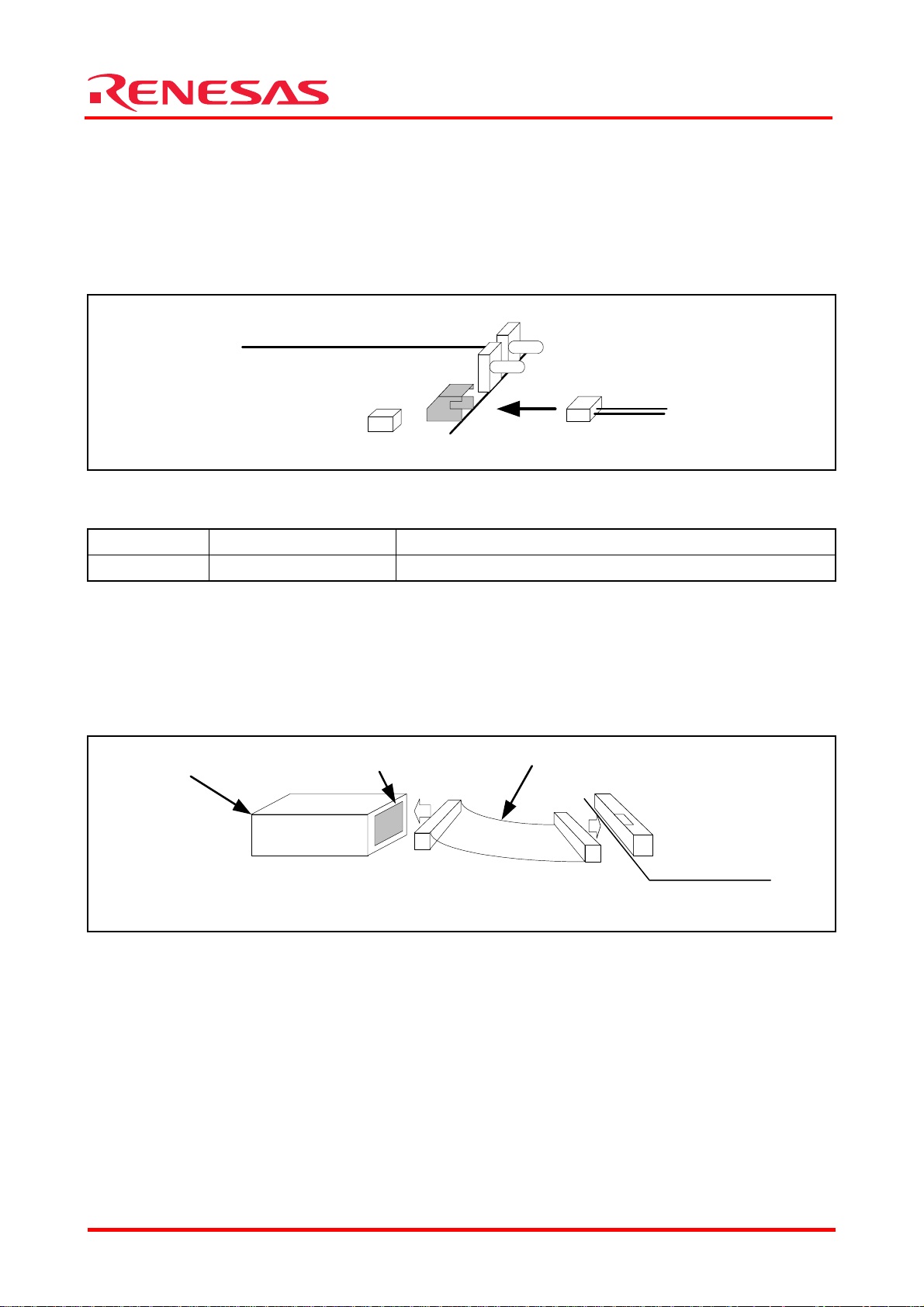
5.1.3 Connecting M3A-2152 Evaluation Board and M32100T-EZ-E
Use included 10-pin flat cable to connect M32100T-EZ-E and XCN1 connector included with the
M3A-2152 Evaluation Board.
The method for Connecting M3A-2152 Evaluation Board and M32100T-EZ-E is shown in Figure
5.3.
M32100T-EZ-E
Figure 5.3 Connecting M3A-2152 Evaluation Board and M32100T-EZ-E
SDI I/F
10-pin flat cable
XCN1
M3A-2152 evaluation board
5.1.4 System Power-on Sequence when M3A-2152G52A in Use
- When turning on power, turn on M32100T-EZ-E first and then the M3A-2152 Evaluation
Board.
- When turning off power, turn off the M3A-2152 Evaluation Board first and then
M32100T-EZ-E.
- When turning on power again after turning off power, wait for 10 seconds.
- Power to M32100T-EZ-E can be fed from USB cable.
Note: Unless the Starter Kit is powered on this sequence, the kit may operate erratically or break down.
REJ10B0224-0300/Rev.3.00 Jan. 2007 Page 13 of 82
Page 20
Starter Kit User’s Manual M3A-2152
5.2 Hardware Setup when M3A-2152G52 in Use
5.2.1 M3A-2195 Power Supply Connection and Settings
The following shows how to set M3A-2195.
For more details, refer to M3A-2195 User’s Manual.
Power to the M3A-2195 SDI Interface Board can be fed from either a 5V DC power supply (5V) or
a 12 DC power supply (6-12V). Use the included 5V or 12V power supply cables to connect
M3A-2195 and a corresponding DC power supply.
The Connecting when Feeding Power to the M3A-21 is shown in Figure 5.4
Feeding from 5V DC ( 4.5 - 5.5V )
or
3 JP1 1
Jumper connector
When feeding from DC 12V(J3)
3 JP1 1
When feeding from DC 5V(J4)
(set as default when shipped from
factory)
Settings of JP1
M3A-2195
J3Feeding from 12V DC ( 6 - 12V )
JP1
J4
Jumper connector
Figure 5.4 Connecting when Feeding Power to the M3A-2195
5.2.2 Connecting to Host PC
In order to control the M3A-2195 SDI Interface Board from M3S-KD32R installed in the host PC,
the host PC’s LPT parallel port and the M3A-2195’s J1 connector should be connected with the
parallel cable included in M3A-2195.
The Connecting the M3A-2195 and Host PC is shown in Figure 5.5
Figure 5.5 Connecting the M3A-2195 and Host PC
32176 Group
REJ10B0224-0300/Rev.3.00 Jan. 2007 Page 14 of 82
Page 21
Starter Kit User’s Manual M3A-2152
5.2.3 M3A-2152 Evaluation Board Power Supply and Settings
The following shows how to set the M3A-2152 Evaluation Board.
Use a 5V DC power supply to feed power to the M3A-2152 Evaluation Board.
Use included 5V power supply cable to connect the 5V DC power supply and CN2 connector
included with the M3A-2152 Evaluation Board. The Connecting when Feeding Power to the
M3A-2152 Evaluation Board is shown in Figure 5.6.
Figure 5.6 Connecting when Feeding Power to the M3A-2152 Evaluation Board
Table 5.4 Jumper Settings before Shipmen
Jumper Name Jumper Settings Remarks
H1 Shorted between 1-2 Uses power from CN2 connector to AVCC power supply
M3A-2152 evaluation board
CN2
H1
4.75 - 5.25V DC power supply
32176 Group
Note: For detail about the power supply settings, refer to Appendix 3 M3A-2152G02 Product Standards
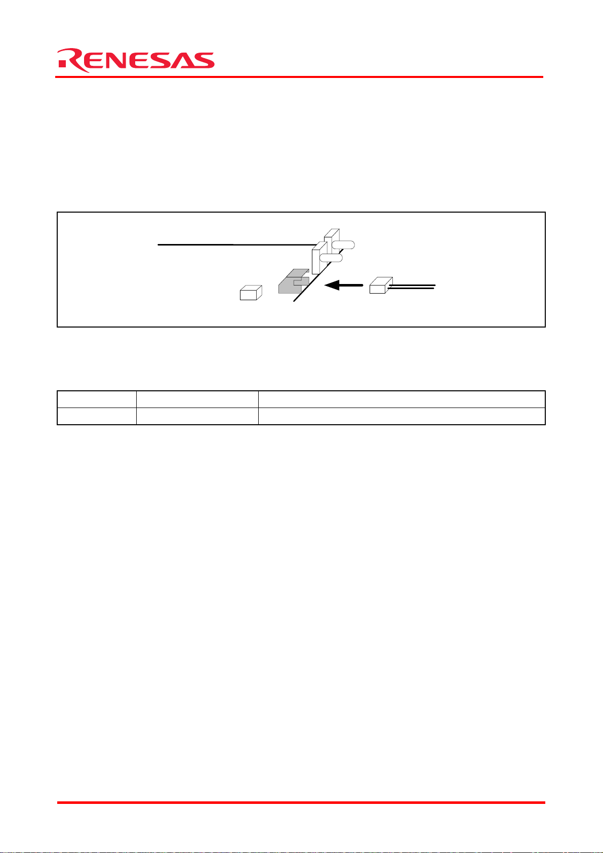
5.2.4 Connecting M3A-2152 Evaluation Board and M3A-2195
Use included 10-pin Flat cable to connect M3A-2195 and XCN1 connector included with the
M3A-2152 Evaluation Board.
The Connecting M3A-2152 Evaluation Board and M3 is shown in Figure 5.7.
M3A-2195
Figure 5.7 Connecting M3A-2152 Evaluation Board and M3A-2195
JTAG
10-pin flat cable
XCN1
M3A-2152 evaluation board
5.2.5 System Power-on Sequence when M3A-2152G52 in Use
- When turning on power, turn on M3A-2195 first and then the M3A-2152 Evaluation Board, or
simultaneously.
- When turning off power, turn off the M3A-2152 Evaluation Board first and then M3A-2195, or
simultaneously.
- When turning on power again after turning off power, wait for 2 seconds.
Note: Unless the Starter Kit is powered on this sequence, the kit may operate erratically or break down.
REJ10B0224-0300/Rev.3.00 Jan. 2007 Page 15 of 82
Page 22
Starter Kit User’s Manual M3A-2152
5.3 Hardware Setup when the Evaluation Board by Itself in Use
5.3.1 M3A-2152 Evaluation Board Power Supply and Settings
The following shows how to set the M3A-2152 Evaluation Board.
Use a 5V DC power supply to feed power to the M3A-2152 Evaluation Board.
Use an included 5V power supply cable to connect the 5V DC power supply and CN2 connector
included with the M3A-2152 Evaluation Board.
The Connecting when Feeding Power to the M3A-2152 Evaluation Board is shown in Figure 5.8.
Figure 5.8 Connecting when Feeding Power to the M3A-2152 Evaluation Board
Before feeding power, make sure jumper switches are set as bellow.
Table 5.5 Jumper Settings before Shipmen
Jumper Name Jumper Settings Remarks
H1 Shorted between 1-2 Uses power from CN2 connector to AVCC power supply
M3A-2152 evaluation board
CN2
H1
4.75 - 5.25V DC power supply
32176 Group
Note: For detail about the power supply settings, refer to Appendix 3 M3A-2152G02 Product Standards
5.3.2 M3A-2152 Power Supply
Connecting the 5V power supply with the included cable turns the M3A-2152 Evaluation Board
powered on.
By disconnecting it, the M3A-2152 Evaluation Board turns powered off.
REJ10B0224-0300/Rev.3.00 Jan. 2007 Page 16 of 82
Page 23
32176 Group
Starter Kit User’s Manual M3A-2152
6. Software Setup
6.1 M3T-PD32RM
M3T-PD32RM is the debugger software that controls M32100T-EZ- E from the host PC.
6.1.1 Installing M3T-PD32RM
[Notes]
Make sure that the installer is executed by one who is authorized as an Administrator when
Windows 2000/XP is used as an operating system of the host machine.
No one but the user who has the authority of an Administrator can install M3T-PD32RM.
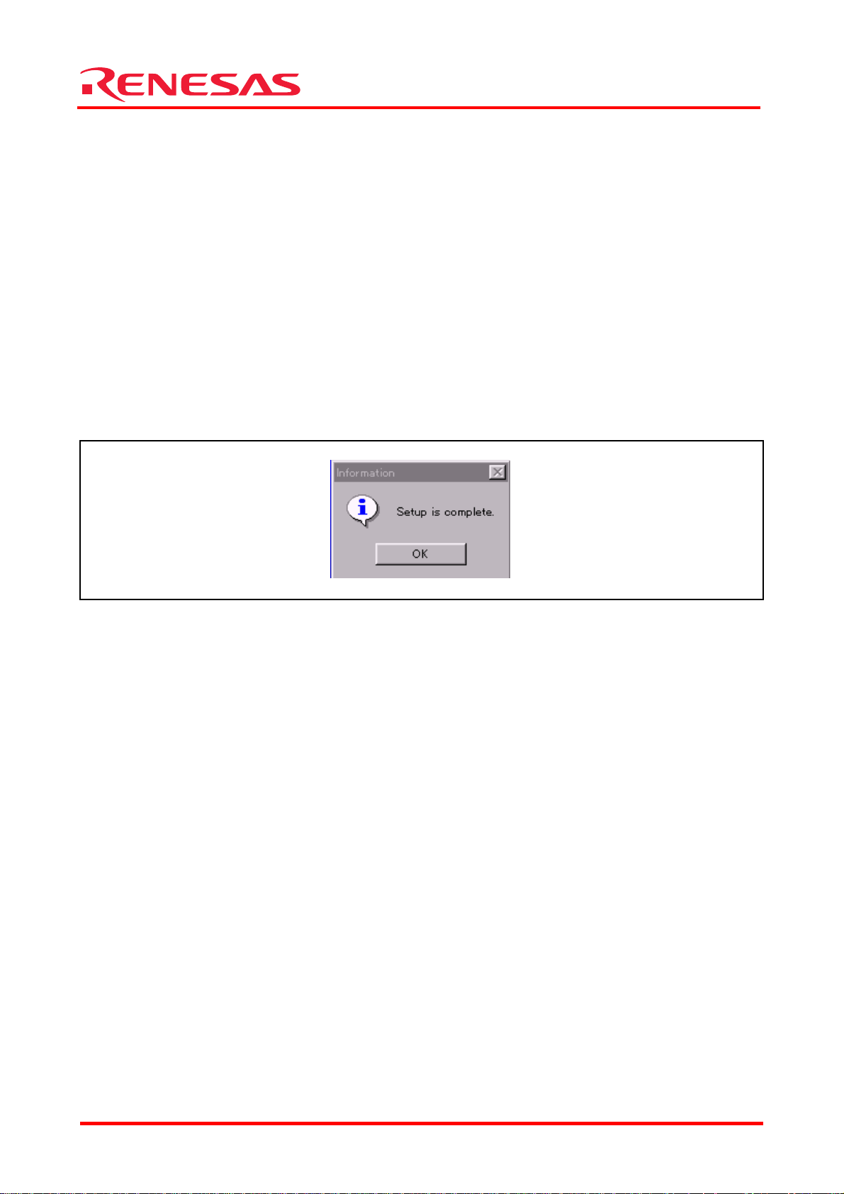
(1) Run pd32rmv301r00_e.exe that is included in the Eng \ Tool \ Pd32rm directory of the CD-ROM.
(2) Proceed to install M3T-PD32RM following messages on the installation screen..
(3) When you finished installing M3T-PD32RM, the dialog box shown in Figure 6.1 appears.
Figure 6.1 Dialog Box when Installation is Finished
REJ10B0224-0300/Rev.3.00 Jan. 2007 Page 17 of 82
Page 24
Starter Kit User’s Manual M3A-2152
p
6.1.2 Starting M3T-PD32RM
Before starting M3T-PD32RM, make sure the hardware components have been set up in
accordance with the instructions in 5.1 Hardware Setup when M3A-2152G52A in Use, and that
the Starter Kit hardware system (M3A-2152 Evaluation Board and M32100T-EZ-E) have been
powered on. Make sure that M3T-PD32RM cannot be started unless the power to the hardware
system is turned on.
To start M3T-PD32RM, choose
[Start] -> [Programs] -> [Renesas] -> [PD32RM V3.01 Release 00] -> [PD32RM]
from Start menu of Windows. When M3T-PD32RM starts, the initialize dialog box shown in
Figure 6.2 appears. So initialize M3T-PD32RM from this dialog box.
Figure 6.2 M3T-PD32RM Initialize Dialog Box
Setting MCU File
To set 32176 Group, specify MCU file “32176.mcu”.
This MCU file is stored in directory: (installed location) \ PD32RM \ M CUFILES.
Click the MCU tab in the initialize dialog box (see Figure 6.2) and then the “Refer” button. This
brings up a dialog box for setting MCU files. In this dialog box, select the MCU file.
Setting Model
While the MCU tab is open, select the appropriate MCU typ e from Model selection.
Setting Mode
While the MCU tab is open, select the appropriate MCU operation mode from Mode selection.
Setting CPU Clock
While the MCU tab is open, select the “40” for the appropriate CPU Clock.
Cancel Hel
32176 Group
REJ10B0224-0300/Rev.3.00 Jan. 2007 Page 18 of 82
Page 25
32176 Group
p
Starter Kit User’s Manual M3A-2152
Checking Serial No.
While the MCU tab is open, make sure the Serial No. is in accordance with the following.
When M3A-2152G52A in use, M3T-PD32RM can be started only with Serial No. as follows.
- In case of M32100T-EZ-E’s limited version included with M3A-2152G52A: 7-digit number
(32176)
Example : 3CE0002(32176)
- In case of the general purpose M32100T-EZ-E: 7-digit number
Example : 3CE0002
Selecting a Cross Tool
While the Debugging Information tab is open, select “CC32R(M32R)” for Compiler.
For the Starter Kit, M3T-CC32R is the only cross tool which has had its operation guaranteed.
Hel
Figure 6.3 Selecting a Cross Tool
When you have finished the above initialization, click the “OK” button to start M3T-PD32RM.
If M3T-PD32RM communicates normally with the target system, it starts up and the
M3T-PD32RM window shown in Figure 6.4 appears. For details on how to use it, refer to the
PD32RM Help.
Figure 6.4 M3T-PD32RM Window at Normal Startup
REJ10B0224-0300/Rev.3.00 Jan. 2007 Page 19 of 82
Page 26
Starter Kit User’s Manual M3A-2152
6.1.3 Error Messages During M3T-PD32RM Startup
If M3T-PD32RM cannot communicate normally with the target system, it appears an error
message in a pop-up box.
Causes of errors on the M3A-2152 Evaluation Board
If the error pop-up box shown in Figure 6.5 appears when starting M3T-PD32RM, check whether
power is supplied to the M3A-2152 Evaluation Board and whether it is firmly connected to
M32100T-EZ-E.
ERROR11473: Target MCU is not under control.
Please reset target systems.
Figure 6.5 Error Message at Startup (Error on the M3A-2152 Evaluation Board Side)
If the error pop-up box is appeared when starting M3T-PD32RM, correct the cause of error and
then click the “OK” button in that pop-up box. This brings up the initialize window, allowing you
to retry the startup. In this case, you can retry only once.
6.1.4 Terminating M3T-PD32RM
To terminate M3T-PD32RM, choose [File] -> [Exit] from the pulldown menu. Then, a dialog box
appears prompting you for your confirmation (see Figure 6.6). Click the “OK” button in that
dialog box to quit M3T-PD32RM. Or click the “Cancel” button, in which case M3T-PD32RM does
not terminate.
Figure 6.6 Dialog Box for Confirming Whether to Quit M3T-PD32RM
Cancel
32176 Group
REJ10B0224-0300/Rev.3.00 Jan. 2007 Page 20 of 82
Page 27
32176 Group
Starter Kit User’s Manual M3A-2152
6.2 M3S-KD32R
M3S-KD32R is the debugger software that controls the M3A-2195 SDI Interface Board from the
host PC.
6.2.1 Installing M3S-KD32R
[Notes for Windows 2000 / NT4.0]
Make sure that installer is executed by one who is authorized as an Administrator.
No one but the user who has the authority of an Administrator can install the M3S-KD32R.
(1) Run SETUP.EXE that is included in the Eng\Tool\Kd32r\W95E directory of the CD-ROM.
(2) Proceed to install M3S-KD32R following messages on the installation screen.
(3) When you finished installing M3S-KD32R, the dialog box shown in appears.
Figure 6.7 Dialog Box when Installation is Finished
(4) Case of using Windows 2000 / NT4.0, after M3S-KD32R is installed, reboot the PC.
REJ10B0224-0300/Rev.3.00 Jan. 2007 Page 21 of 82
Page 28
32176 Group
p
Starter Kit User’s Manual M3A-2152
6.2.2 Starting M3S-KD32R
Before starting M3S-KD32R, make sure the hardware components have been set up in
accordance with the instructions in 5.2 Hardware Setup when M3A-2152G52 in Use, and that
the Starter Kit hardware system (M3A-2152 Evaluation Board and M3A-2195 SDI Interface
Board) have been powered on. Make sure that M3S-KD32R cannot be started unless the power to
the hardware system is turned on.
To start M3S-KD32R,
choose [Start] -> [Programs] -> [RENESAS-TOOL] -> [KD32R V4.00 Release 1] -> [KD32R] from
Start menu of Windows. When M3S-KD32R starts, the initialize dialog box shown in Figure 6.2
appears. So initialize
M3S-KD32R from this dialog box.
Figure 6.8 M3S-KD32R Initialize Dialog Box
Setting MCU File
To set 32176 Group, specify MCU file “32176.mcu”.
This MCU file is stored in directory: ( installed location) \ KD32R \ MCUFILES.
Click the MCU tab in the initialize dialog box (see Figure 6.2) and then the “Refer” button. This
brings up a dialog box for setting MCU files. In this dialog box, select the MCU file.
Setting Model
While the MCU tab is open, select the appropriate MCU typ e from Model selection.
Setting Mode
While the MCU tab is open, select the appropriate MCU operation mode from Mode selection.
Setting CPU Clock
While the MCU tab is open, select the “40” for the appropriate CPU Clock.
Setting PC Communication Mode
While the MCU tab is open, select “AUTO” for Type, and “378h” or “278h” for I/O Address.
Hel
REJ10B0224-0300/Rev.3.00 Jan. 2007 Page 22 of 82
Page 29

Starter Kit User’s Manual M3A-2152
p
Selecting a Cross Tool
While the Debugging Information tab is open, select “CC32R(M32R)” for Compiler.
For the Starter Kit, M3T-CC32R is the only cross tool which has had its operation guaranteed.
Cancel Hel
Figure 6.9 Selecting a Cross Tool
When you have finished the above initialization, click the “OK” button to start M3S-KD32R.
If M3S-KD32R communicates normally with the target system, it starts up and the M3S-KD32R
window shown in Figure 6.10 appears. For details on how to use it, refer to the M3S-KD32R
Release Note and the PD32R Help.
Figure 6.10 M3S-KD32R Window at Normal Startup
32176 Group
REJ10B0224-0300/Rev.3.00 Jan. 2007 Page 23 of 82
Page 30

Starter Kit User’s Manual M3A-2152
6.2.3 Error Messages During M3S-KD32R Startup
If M3S-KD32R cannot communicate normally with the target system, it appears an error
message in a pop-up box.
Causes of Errors on the SDI Interface Board Side
If the error pop-up box shown in Figure 6.11 appears when starting M3S-KD32R, check whether
power is supplied to the M3A-2195 SDI Interface Board and whether it is firmly connected to the
host PC with a cable (LPT parallel cable).
Can’t connect with the target
ERROR(1705)
Figure 6.11 Error Message at Startup (Error on M3A-2195 Side)
Causes of Errors on the M3A-2152 Evaluation Board
If the error pop-up box shown in Figure 6.12 appears when starting M3S-KD32R, check whether
power is supplied to the M3A-2152 Evaluation Board and whether it is firmly connected to
M3A-2195 SDI Interface Board.
ERROR11473: Target MCU is not under control.
Please reset target systems.
Figure 6.12 Error Message at Startup (Error on the M3A-2152 Evaluation Board Side)
If the error pop-up box is appeared when starting M3S-KD32R, correct the cause of error and
then click the “OK” button in that pop-up box. This brings up the initialize window, allowing you
to retry the startup. In this case, you can retry only once.
6.2.4 Terminating M3S-KD32R
To terminate M3S-KD32R, choose [File] -> [Exit] from the pulldown menu. Then, a dialog box
appears prompting you for your confirmation (see Figure 6.13). Click the “OK” button in that
dialog box to quit M3S-KD32R. Or click the “Cancel” button, in which case M3S-KD32R does not
terminate.
Figure 6.13 Dialog Box for Confirming Whether to Quit M3S-KD32R
Cancel
32176 Group
REJ10B0224-0300/Rev.3.00 Jan. 2007 Page 24 of 82
Page 31

32176 Group
Starter Kit User’s Manual M3A-2152
6.3 M3T-CC32R
6.3.1 Installing M3T-CC32R
(1) Run cc32rv500r00_e.exe that is included in the Eng \ Tool \ Cc32r directory of the CD-ROM.
(2) Proceed to install M3T-CC32R following messages on the installation screen.
(3) When you are asked to select the license type of M3T-CC32R, select “Trial License”.
(4) While installing M3T-CC32R, you will be asked to confirm whether to change AUTOEXEC.BAT
variables. If you chose “Not to Change”, add the following contents to AUTOEXEC.BAT.
(Setting example for M3T-CC32R environment variables)
REM *********** Environment variables for CC32R ****************
SET M32RBIN = (installed directory) ¥bin32R
SET M32RLIB = (installed directory) ¥lib32R
SET M32RINC = (installed directory) ¥inc32R
SET M32RTMP = (installed directory) ¥TMP
SET PATH=%M32RBIN%;%PATH%
(5) If you corrected AUTOEXEC.BAT, be sure to restart your computer after you finished installing
M3T-CC32R.
6.3.2 Verifying Whether M3T-CC32R is Installed Normally
Execute the following operation from the DOS prompt. This helps to verify whether M3T-CC32R
has been installed normally. For details about M3T-CC32R, refer to the CC32R User’s Manual.
- Command
C: \ >cc32r -V (V in uppercase)
- Result
If M3T-CC32R has been installed normally, a command version of M3T-CC32R like the one
shown below is displayed.
CC32R Compiler for M32R Family V.X
Copyright 1995-XXXX
AND RENESAS SOLUTIONS CORPORATION
ALL RIGHT RESERVED
(X
varies with the version of the Cross Tool Kit included in the package.)
Displayed below this is the version information of each tool i ncluded in the Cross Tool Kit.
RENESAS TECHNOLOGY CORPORATION
.XX Release X
- If M3T-CC32R does not start
If M3T-CC32R does not start, check the following.
1) See if the environmental variables (M32RBIN, M32LIB, M32RINC, M32RTMP command
paths) are set correctly.
2) See if cc32r.exe is correctly expan ded in the directory specified in M32RBIN.
6.4 Browsing Electronic Manuals
The Starter Kit manuals each are provided as Portable Document Format (PDF) files.
To browse electronic manuals, you need to have Acrobat Reader. The CD-ROM supplied with the
Starter Kit contains Acrobat Reader in its Acrobat directory, so install the desired version of
Acrobat Reader from the CD-ROM. Acrobat Reader can also be downloaded from the Adobe Systems
home page.
REJ10B0224-0300/Rev.3.00 Jan. 2007 Page 25 of 82
Page 32

32176 Group
Starter Kit User’s Manual M3A-2152
Appendix 1 Contents of CD-ROM
1. Contents of CD-ROM
The CD-ROM contains the software, manuals, various data sheets, and sample programs which are
needed for you to use the Starter Kit.
When using the technical contents of the CD-ROM such as product data, diagrams, and tables or the
programs and algorithms also included in the CD-ROM for your application, please be sure to
evaluate those technical contents, programs, and algorithms as the whole system, and not
individually as single items before you determine whether they are useful. Renesas Technology
Corporation will not assume any responsibility regarding the ir suita bility for your application.
The following shows directory configurations and contents of the CD-ROM.
Jpn/ Eng + Readme_j.txt/ Readme_e.txt : README file
+ AcrobatReader : Tool for read pdf file
+ Tool + : Software for the M32R Family
| + Cc32r : Cross Tool Kit for the M32R Family (Trial version)
| + Pd32rm : Debugger for the M32R Family
| + Kd32r : Debugger for the M32R Family
| + Ufla32r : Flash memory reprogramming kit for M32R/ECU by UART
| + Oldversion : Old version of Tools
|
+ Document + : Materials associated with boards
| + M3A-2114 : Materials associated with the 32170/32174/32171/32172/32173
| Evaluation board (M3A-2114)
| + M3A-2142 : Materials associated with the 32180/32182 Evaluation board
| (M3A-2142)
| + M3A-2152 : Materials associated with the 32176 Evaluation board
| (M3A-2152)
| + M3A-2154 : Materials associated with the 32185/32186/32192/32195/32196
| Evaluation board (M3A-2154)
| + M3A-2191 : Connector Pitch Converter for M3A-2114 Evaluation board
| and M32100T-EZ-E
| + M32100T-EZ-E : Materials associated with the Emulator for M32R
| + M3A-2145 : Manual for Flash memory reprogramming kit (Ufla32r)
| + Discontinued_model : Materials associated with the discontinued boards (M3A-2195)
|
+ Manual : M32R/ECU manuals, data sheets, M32R Family
| software manuals
+ SampleProgram : Application notes and listed object/source files
REJ10B0224-0300/Rev.3.00 Jan. 2007 Page 26 of 82
Page 33

32176 Group
Starter Kit User’s Manual M3A-2152
1.1 Acrobat
The CD-ROM contains files necessary to read manuals (PDF files). The documents included in the
CD-ROM have been verified to be displayed and printed using the following versions of Acrobat. If
you have trouble displaying or printing documents with other Acrobat versions, install the
appropriate Acrobat version from the CD-ROM into your computer.
(English version)
Eng + AcrobatReader + V3 + (For Windows95)
| + Ar32e301.EXE : PDF reader installation software
| + Readme.txt : README file
+ V4 + (For Version4)
| + ArR0ENG.EXE : PDF reader installation software
| + Readme.txt : README file
+ Win16e + (For Wi ndows3.1)
+ AR16E301.EXE : PDF reader installation software
+ Readme.txt : README file
(Japanese version)
Jpn + AcrobatRead er + AR40JPN.EXE : PDF reader installation software
+ Readme.txt : README file
REJ10B0224-0300/Rev.3.00 Jan. 2007 Page 27 of 82
Page 34

32176 Group
Starter Kit User’s Manual M3A-2152
1.2 Tool
(1) M3T-CC32R
M3T-CC32R (Cross Tool Kit for the M32R Family, trial version whose useful period is limited) is
included. Its directory structure is shown below.
(English version)
Eng+Tool+Cc32r+
+ cc32rv500r00_e.exe : Setup programs for M3T-CC32R
+ rej10j0931_as32r_u.pdf : M3T-CC32R user’s manual (Assembler)
+ rej10j0930_cc32r_u.pdf : M3T-CC32R user’s manual (C Compiler)
+ mapue.pdf : MAP Viewer user’s manual
(Japanese version)
Jpn+Tool+Cc32r+
+ cc32rv500r00_j.exe : Setup programs for M3T-CC32R
+ as32ruj.pdf : M3T-CC32R user’s manual (Assembler)
+ cc32ruj.pdf : M3T-CC32R user’s manual (C Compiler)
+ mapuj.pdf : MAP Viewer user’s manual
(2) M3T-PD32RM
M3T-PD32RM (Debugger for M32100T-EZ-E) is included. This debugger software
(Windows-compliant version) is used to control the microcomputer on the evaluation board from
the host PC by connecting M32100T-EZ-E and the host PC with USB cable.
Its directory structure is shown below.
(English version)
Eng+Tool+Pd32rm+
+ pd32rmv301r00_e.exe : Setup programs for M3T -PD32RM
+ rej10j1494_pd32rm_n.pdf : M3T-PD32RM release note
(Japanese version)
Jpn+Tool+Pd32rm+
+ pd32rmv301r00_j.exe : Setup programs for M3T-PD32RM
+ rjj10j1800_pd32rm_n.pdf : M3T-PD32RM release note
REJ10B0224-0300/Rev.3.00 Jan. 2007 Page 28 of 82
Page 35

Starter Kit User’s Manual M3A-2152
(3) M3S-KD32R (Discontinued)
M3S-KD32R (Debugger for the Starter Kit) is included. This debugger software (Windows
-compliant version) is used to control the microcomputer on the evaluation board from the host
PC by connecting it and the host PC with LPT parallel cable through the M3A-2195 (SDI
Interface Board). Its directory structure is shown below.
(English version)
Eng+Tool+Kd32r+
+ KD32RNE.pdf : M3S-KD32R release note
+ W95E : Setup programs for M3S-KD32R
(Japanese version)
Jpn+Tool+Kd32r+
+ KD32RNJ.pdf : M3S-KD32R release note
+ W95J : Setup programs for M3S-KD32R
(4) M3S-UFLA32R
M3S-UFLA32R is included. M3S-UFLA32R is the software to program into internal flash
memory on M32R/ECU series 3217x, 3218x Group microcomputers from Windows version
personal computer(PC/AT), by using UART communication. Its directory structure is shown
below.
(English version)
Eng+Tool+Ufla32r+
+ UFLA32Rue.pdf : M3S-UFLA32R user’s manual
+ W95E : Setup programs for M3S-UFLA32R
(Japanese version)
Jpn+Tool+Ufla32r+
+ UFLA32Ruj.pdf : M3S-UFLA32R user’ s manual
+ W95J : Setup programs for M3S-UFLA32R
32176 Group
REJ10B0224-0300/Rev.3.00 Jan. 2007 Page 29 of 82
Page 36

(5) Oldversion
Old versions of tools are included.
Its directory structure is shown below.
(English version)
Eng+Tool+Oldversion+
+ Cc32rv3 : Objects for M3T-CC32R Version 3
+ Cc32rv41 : Objects for M3T-CC32R Version 4.1
+ Cc32rv42 : Objects for M3T-CC32R Version 4.2
+ Cc32rv43 : Objects for M3T-CC32R Version 4.3
+ Pd32rmv2 : Objects for M3T-PD32RM Version 2
+ Pd32rmv21 : Objects for M3T-PD32RM Version 2.1
+ Pd32rmv3 : Objects for M3T-PD32RM Version 3
+ Kd32rv3 : Objects for M3S-KD32R Version 3
(Japanese version)
Jpn+Tool+Oldversion+
+ Cc32rv3 : Objects for M3T-CC32R Version 3
+ Cc32rv41 : Objects for M3T-CC32R Version 4.1
+ Cc32rv42 : Objects for M3T-CC32R Version 4.2
+ Cc32rv43 : Objects for M3T-CC32R Version 4.3
+ Pd32rmv2 : Objects for M3T-PD32RM Version 2
+ Pd32rmv21 : Objects for M3T-PD32RM Version 2.1
+ Pd32rmv3 : Objects for M3T-PD32RM Version 3
+ Kd32rv3
+ Ufla32rv13
32176 Group
Starter Kit User’s Manual M3A-2152
: Objects for M3S-KD32R Version 3
: Objects for M3S-UFLA32R Version 1.3
REJ10B0224-0300/Rev.3.00 Jan. 2007 Page 30 of 82
Page 37

Starter Kit User’s Manual M3A-2152
1.3 Manual
The M32R Family related manuals and data sheets are included in PDF file format.
(English version)
Eng + Manual +
+ Readme_e.txt : README file
+ e32rsm.pdf : M32R Family software manual
+ rej09b0112 _32 fpusm.pdf : M32R-FPU software manual
+ e32170um.pdf : 32170/32174 Group user’s manual
+ e32172um.pdf : 32172/32173 Group user’s manual
+ rej06b0048_32180um.pdf : 32180 Group user’ s manual
+ rej09b0014_32182um.pdf : 32182 Group user’ s manual
+ rej09b0015_32171um.pdf : 32171 Group user’ s manual
+ rej09b0067-0110_32176hm.pdf : 32176 Group hardware manual
+ rej09b0123-0101_32192hm.pdf : 32192/32196 Group hardware manual
+ rej09b0235_32186hm.pdf : 32186 Group hardware manual
(Japanese version)
Jpn + Manual +
+ Readme_j.txt : README fi le
+ j32rsm.pdf : M32R Family software manual
+ rjj09b0107_32fpusm.pdf : M32R-FPU software manual
+ rjj09b0123_32176no.pdf : 32176 Group precautions
+ j32170um.pdf : 32170/32174 Group user’s manual
+ j32171um.pdf : 32171 Group user’s manual
+ j32172um.pdf : 32172/32173 Group user’s manual
+ j32180um.pdf : 32180 Group user’s manual
+ rjj09b0001_32176um.pdf : 32176 Group user’s manual
+ rjj09b0053_32182um.pdf : 32182 Group user’s manual
+ rjj09b0099_32192hm.pdf : 32192/32195/32196 Group hardware manual
+ rjj09b0246-0100_32186hm.pdf : 32186 Group hardware manual
+ 32470210j.pdf : Errata table for 32182 Group user’s manual
+ 32580401j.pdf : Err a t a t a b l e f or 3 2 170/321 74 Group user’s manual
+ 32590401j.pdf : Errata table for 32171 Group user’s manual
+ 32630402j.pdf : Errata table for 32180 Group user’s manual
+ 32680404j.pdf : Err a t a t a b l e f or 3 2 172/321 73 Group user’s manual
+ tn32ra074aj.pdf : Errata table for 32186 Group user’s manual
32176 Group
REJ10B0224-0300/Rev.3.00 Jan. 2007 Page 31 of 82
Page 38

32176 Group
Starter Kit User’s Manual M3A-2152
1.4 Board Related Manual (Document)
The product standards, part list, connection diagrams and user’s manuals for the evaluation board
in Starter Kit are included in PDF file format.
(1) M3A-2114 Evaluation Board related documents
The related documents for the 32170/32171/32172/32173/32174 Group Evaluation Board are
included in PDF file format.
(English version)
Eng+Document+M3A-2114+
+ Readme_e.txt : README file
+ 2114um_e.pdf : M3A-21 14 Starter Kit use’s manual
+ 2114g02sk_e.pdf : M3A-2114G02 product standards
+ 2114g12sk_e.pdf : M3A-2114G12 product standards
+ 2114g22sk_e.pdf : M3A-2114G22 product standards
+ cdrom_e.pdf : Content list of CD-ROM
(Japanese version)
Jpn+Document+M3A-2114+
+ Readme_j.txt : README file
+ 2114um_j.pdf : M3A-2114 Starter Kit use’s manual
+ 2114g02sk_j.pdf : M3A-2114G02 product standards
+ 2114g12sk_j.pdf : M3A-2114G12 product standards
+ 2114g22sk_j.pdf : M3A-2114G22 product standards
+ cdrom_j.pdf : Content list of CD-ROM
(2) M3A-2142 Evaluation Board related documents
The related documents for the function extension board and the 32180/32182 Group Evaluation
Board are included in PDF file format.
(English version)
Eng+Document+M3A-2142+
+ Readme_e.txt : README file
+ 2142um_e.pdf : M3A-2142 Starter K it u s e’s manual
+ 2142g01sk_e.pdf : M3A-2142G01 product standards
+ 2142g03sk_e.pdf : M3A-2142G03 product standards
+ cdrom_e.pdf : Content list of CD-ROM
(Japanese version)
Jpn+Document+M3A-2142+
+ Readme_j.txt : README file
+ 2142um_j.pdf : M3A-2142 Starter K it u s e’s manual
+ 2142g01sk_j.pdf : M3A-2142G01 product standards
+ 2142g03sk_j.pdf : M3A-2142G03 product standards
+ cdrom_j.pdf : Content list of CD-ROM
REJ10B0224-0300/Rev.3.00 Jan. 2007 Page 32 of 82
Page 39

32176 Group
Starter Kit User’s Manual M3A-2152
(3) M3A-2152 Evaluation Board related documents
The related documents for the 32176 Group Evaluation Board are inc luded in PDF file format.
(English version)
Eng+Document+M3A-2152+
+ Readme_e.txt : README f i le
+ rej10b0224_2152um.pdf : M3A-2152 Starter Kit use’s manual
(Japanese version)
Jpn+Document+M3A-2152+
+ Readme_j.txt : README file
+ rjj10b0233_2152um.pdf : M3A-2152 Starter Kit use’s manual
(4) M3A-2154 Evaluation Board related documents
The related documents for the 32185/32186/32192/32195/32196 Group Evaluation Board are
included in PDF file format.
(English version)
Eng+Document+M3A-2154+
+ Readme_e.txt : README file
+ rej10b0223_2154um.pdf : M3A-2154 Starter Kit use’s manual
(Japanese version)
Jpn+Document+M3A-2154+
+ Readme_j.txt : README file
+ rjj10b0231_2154um.pdf : M3A-2154 Starter Kit use’s manual
(5) M32100T-EZ-E related documents
M32100T-EZ-E documents are included in PDF file format.
(English version)
Eng+Document+M32100T-EZ-E+
+ Readme_e.txt : README file
+ rej10j0002_m32100teze_u.pdf : M32100T-EZ-E use’s manual
+ rej10j0013_m32100teze_s.pdf : M32100T-EZ-E release note
(Japanese version)
Jpn+Document+M32100T-EZ-E+
+ Readme_j.txt : README file
+ rjj10j0002_m32100teze_u.pdf : M32100T-EZ-E use’s manual
+ rjj10j0014_m32100teze_s.pdf : M32100T-EZ-E release note
REJ10B0224-0300/Rev.3.00 Jan. 2007 Page 33 of 82
Page 40

Starter Kit User’s Manual M3A-2152
(6) M3A-2191 Pitch Converter related documents
The M3A-2114 Evaluation Board and M3A-2195 Interface Board connecting pitch converter
related documents are included in PDF file format.
(English version)
Eng+Document+M3A-2191+
+ Readme_e.txt : README file
+ rej10b0228_2191sk.pdf : M3A-2191 product standards
+ cdrom_e.pdf : Content list of CD-ROM
(Japanese version)
Jpn+Document+M3A-2191+
+ Readme_j.txt : README file
+ rjj10b0237_2191sk.pdf : M3A-2191 product standards
+ cdrom_j.pdf : Content list of CD-ROM
(7) M3A-2145 Evaluation Board related documents
The related documents for the M3S-UFLA32R are included in PDF file format.
(English version)
Eng+Document+M3A-2145+
+ Readme_e.txt : README file
+ 2145g50sk_e.pdf : M3A-2145G50 product standards
+ 2145g02sk_e.pdf : M3A-2145G02 product standards
+ 2145g50p_e.pdf : M3A-2145G50 part list
+ 2145g02p_e.pdf : M3A-2145G02 part list
+ cdrom_e.pdf : Content list of CD-ROM
(Japanese version)
Jpn+Document+M3A-2145+
+ Readme_j.txt : README file
+ 2145g50sk_j.pdf : M3A-2145G50 product standards
+ 2145g02sk_j.pdf : M3A-2145G02 product standards
+ 2145g50p_j.pdf : M3A-2145G50 part list
+ 2145g02p_j.pdf : M3A-2145G02 part list
+ cdrom_j.pdf : Content list of CD-ROM
32176 Group
REJ10B0224-0300/Rev.3.00 Jan. 2007 Page 34 of 82
Page 41

Starter Kit User’s Manual M3A-2152
(8) M3A-2195 SDI Interface Board related documents (Discontinued)
The SDI Interface Board documents are included in PDF file format.
(English version)
Eng+Document+Discontinued_model+M3A-2195+
+ Readme_e.txt : README file
+ 2195g50sk_e.pdf : M3A-2195G50 product standards
+ 2195c_e.pdf : M3A-2195 Evaluation Board connection diagram
+ 2195p_e.pdf : M3A-2195 part list
+ 2195g50p_e.pdf : M3A-2195G50 part list
+ 2195um_e.pdf : M3A-2195 user’s manual
+ cdrom_e.pdf : Content list of CD- ROM
(Japanese version)
Jpn+Document+Discontinued_model+M3A-2195+
+ Readme_j.txt : README file
+ 2195g50sk_j.pdf : M3A-2195G50 product standards
+ 2195c_j.pdf : M3A-2195 Evaluation Board connection diagram
+ 2195p_j.pdf : M3A-2195 part list
+ 2195g50p_j.pdf : M3A-2195G50 part list
+ 2195um_j.pdf : M3A-2195 user’s manual
+ cdrom_j.pdf : Content list of CD-ROM
(9) M3A-2128 Evaluation Board related documents (Discontinued)
The related documents for the 32170 Group Evaluation Board are inc luded in PDF file format.
(Japanese version)
Jpn+Document+Discontinued_model+M3A-2128+
+ Readme_j.txt : README file
+ 2128im_j.pdf : M3A-2128 installation manual
+ 2128um_j.pdf : M3A-2128 Starter Kit user’s manual
+ 2128sk_j.pdf : M3A-2128 product standards
+ 2128g50p_j.pdf : M3A-2128G50 part list
+ cdrom_j.pdf : Content list of CD-ROM
(10) M3A-2154 Evaluation Board related documents (Discontinued)
The related documents for the 32192 Group Evaluation Board are inc luded in PDF file format.
(English version)
Eng+Document+Discontinued_model+M3A-2154G52A+
+ Readme_e.txt : README file
+ 2154g52aum_e.pdf : M3A-2154 Starter Kit user’s manual
+ 2154g02sk_e.pdf : M3A-2154G02 product standards
(Japanese version)
Jpn+Document+Discontinued_model+M3A-2154G52A+
+ Readme_j.txt : README file
+ 2154g52aum_j.pdf : M3A-2154 Starter Kit user’s manual
+ 2154g02sk_j.pdf : M3A-2154G02 product standards
32176 Group
REJ10B0224-0300/Rev.3.00 Jan. 2007 Page 35 of 82
Page 42

Starter Kit User’s Manual M3A-2152
(11) M3A-2142G04 Board related documents (Discontinued)
The related documents for the MCU pin processing Boar d are included in PDF file format.
(English version)
Eng+Document+Discontinued_model+M3A-2142G04+
+ Readme_e.txt : README file
+ 2142g04sk_e.pdf : M3A-2142G04 product standards
+ cdrom_e.pdf : Content list of CD-ROM
(Japanese version)
Jpn+Document+Discontinued_model+M3A-2142G04+
+ Readme_j.txt : README file
+ 2142g04sk_j.pdf : M3A-2142G04 product standards
+ cdrom_j.pdf : Content list of CD-ROM
32176 Group
REJ10B0224-0300/Rev.3.00 Jan. 2007 Page 36 of 82
Page 43

32176 Group
Starter Kit User’s Manual M3A-2152
1.5 Sample Program
The application notes, the object and source files of sample programs for the M32R/ECU’s
peripheral functions to be written into the M32R/ECU’s internal flash memory that can be used on
the Evaluation Board for Starter kit, are included i n the CD-ROM
(English version)
Eng+SampleProgram+
+ 32170_32171 : 32170/32171 Group application notes and sample programs
+ 32172_32173 : 32172/32173 Group application notes and sample programs
+ 32176 : 32176 Group application notes and sample programs
+ 32180_32182 : 32180/32182 Group application notes and sample programs
+ 32185_32186 : 32185/32186 Group application notes and sample programs
+ 32192_32195_32196 : 32192/32195/32196 Group application notes and
sample programs
(Japanese version)
Jpn+SampleProgram+
+ Readme.html : README file
+ 32170_32171 : 32170/32171 Group application notes and sample programs
+ 32172_32173 : 32172/32173 Group application notes and sample programs
+ 32176 : 32176 Group application notes and sample programs
+ 32180_32182 : 32180/32182 Group application notes and sample programs
+ 32185_32186 : 32185/32186 Group application notes and sample programs
+ 32192_32195_32196 : 32192/32195/32196 Group application notes and
sample programs
REJ10B0224-0300/Rev.3.00 Jan. 2007 Page 37 of 82
Page 44

Appendix 2 Part List
A part list is pro vided in following pages for your reference.
32176 Group
Starter Kit User’s Manual M3A-2152
REJ10B0224-0300/Rev.3.00 Jan. 2007 Page 38 of 82
Page 45
REJ10B0224-0300/Rev.3.00 Jan. 2007 Page 39 of 82
Division in charge
Remarks
Supply
Classification
Unit
Q’ty per
Required
Direction
Mounting
1
1
1
1
1
1
1
PLL-M3A-2152G52A ( 1 / 1 )
M3A-2152G52A
Title
PPL-M3A-2152G52A
No.
Part List
Classification
Manufacturer Name
Specification)
Part Type Name
(Drawing No.,Product
PLL-M3A-2152G02 M3A-2152G02
Part Name Part Specification
Description Part No.
M32100T-EZ-E
Special note:
M32R/ECU#4NL
Evaluation board
Emulator for 32176
Group MCU
IMPORTANT-READ ME
FIRST
M32R/ECU Starter kit
Release note
1
2
3 USB cable
4 10-pin flat cable
5 CD-ROM
6
Handling
Created Revision
Checked
Item No.
*
7
(2) If two or more part type names are written for one part, the upper row has priority.
(3) The asterisk (*) in the item No. column denotes that the rest is blank.
Special note:
(1) Blank columns denote the same content as the upper row.
Page 46

REJ10B0224-0300/Rev.3.00 Jan. 2007 Page 40 of 82
Division in charge
Remarks
Supply
Classification
Unit
Q’ty per
Required
Direction
Mounting
1
1
1
1
1
1
1
PLL-M3A-2152G52 ( 1 / 1 )
M3A-2152G52
Title
PPL-M3A-2152G52
No.
Part List
Classification
Manufacturer Name
Specification)
Part Type Name
(Drawing No.,Product
PLL-M3A-2152G02 M3A-2152G02 1
Part Name Part Specification
Description Part No.
Special note:
M32R/ECU#4NL
Evaluation board
IMPORTANT-READ ME
FIRST
M32R/ECU Starter kit
Release note
1
2 Simple Emulator probe PLL-M3A-2195 M3A-2195 1
3 5V power supply cable
4 12V power supply cable
5 Parallel cable
6 10-pin flat cable
7 CD-ROM
8
Handling
Created Revision
Checked
Item No.
*
9
(2) If two or more part type names are written for one part, the upper row has priority.
(3) The asterisk (*) in the item No. column denotes that the rest is blank.
Special note:
(1) Blank columns denote the same content as the upper row.
Page 47

Starter Kit User’s Manual M3A-2152
Appendix 3 M3A-2152G02 Product Standards
This manual describes how to operate the M3A-2152G02 (32176 Group Evaluation Board)
32176 Group
REJ10B0224-0300/Rev.3.00 Jan. 2007 Page 41 of 82
Page 48

32176 Group
Starter Kit User’s Manual M3A-2152
1. Overview
1.1 Outline of the Product
Table 1.1 Mounted Microcomputer Type
Mounted microcomputer type name M32176F4VFP
Evaluation board type name (socket mounted type) M3A-2152G02
Table 1.2 Specification of Product
Operation mode Single-chip mode, Processor mode and External extension mode
Board extension Can be extended using the board’s extension connector
CAN I/F Comes standard with a 2-channel CAN connector, CAN modular cord included
RS-232C I/F Comes standard with an RS-232C connector
Serial port One of four channels can be selected using a rotary switch
Analog port Inputs on two channels can be controlled using variable resistor (VR) controls
Display I/O Comes with a single-port LED
Input I/O Comes with a single-port toggle switch
VR controls
LED indicator
(port output)
External
extension
connector
Toggle switch
(port input)
Figure 1.1 Photograph of the M3A-2152G02
Power supply connector
LED indicator
(power-on)
CAN connector
JTAG connector
Reset key
RS-232C connector
Rotary switch
(selects a serial I/O channel)
REJ10B0224-0300/Rev.3.00 Jan. 2007 Page 42 of 82
Page 49

1.2 External View
An external view of the M3A-2152G02 is shown below.
Figure 1.2 External View of the M3A-2152G02
32176 Group
Starter Kit User’s Manual M3A-2152
REJ10B0224-0300/Rev.3.00 Jan. 2007 Page 43 of 82
Page 50

1.3 Block Diagram
A block diagram of th e M3A-2152G02 is shown below.
RS-232C
cable
RS-232C
connector
CAN
connector
VCCE
power supply
connector
Figure 1.3 Block Diagram of the M3A-2154G02A
Host machine
(DOS/V)
Serial I/O
channel select
RS-232C
driver
CAN
driver
Oscillator
circuit
8
8
4
Extension connector
(JTAG, MCU control and
Port
M32176F4VFP
MOD0/
MOD1
SIO
PORT13
PORT11
CAN
XIN
VCCE
AVCC/VDDE
JTAG
RESET
Starter Kit User’s Manual M3A-2152
Extension board
144
144
other pins excluded)
FP
8
5
2
AD
(JTAG, MCU control and
other pins excluded)
2
FP select
MOD
select
JTAG
connector
Reset
circuit
32176 Group
REJ10B0224-0300/Rev.3.00 Jan. 2007 Page 44 of 82
Page 51

Starter Kit User’s Manual M3A-2152
1.4 Specifications of the Evaluation Board
1.4.1 Electrical Characteristics
Table 1.3 Electrical Characteristics
Symbol Parameter Rated Value
VCCE, AVCC Power supply voltage 4.75 V to 5.25 V
Tstr Storage ambient temperature 0°C to 70°C
Topr Operating ambient temperature 0°C to 70°C
Note: Operating conditions require that no dewdrops and corrosive gas be present.
1.4.2 Functional Characteristics
Table 1.4 Functional Characteristics
Item M3A-2152G02
M32176F4VFP(U1)
CPU
Clock input: 10 MHz; CPU clock: 40 MHz
Flash memory 512 KB
Memory
SRAM 24 KB
32176 Group
RS-232C interface
JTAG interface Comes standard with an SDI connector (XCN1)
CAN interface
VCCE Power supply, Connector (CN2)
Power
supply
General-purpose output LED indicators (L0–L7), CPU ports (P110–P117)
General-purpose input Toggle switches (S0–S7), CPU ports (P130–P137)
Reset
Serial I/O Rotary switch (SW2), which selects one of four serial I/O channels
Analog input
Extension Extension connectors (CON1, CON2)
AVCC Analog circuit power supply, Connector (CN1)
LED Illuminates in red when powered on (LED1)
Comes standard with a 9-pin Dsub connector (CN5) for serial
communication with the host PC (DOS/V)
Comes standard with a 2-channel connector for CAN communication (CN4),
a CAN-to-Dsub connector (9-pin) conversion cord included
Reset switch (SW1), reset input (red pushbutton)
*Please be careful to configure a reset circuit according to your
system.
VR controls (VOL0, VOL1)
Connects these VR controls with AD0IN0 and AD0IN1 to use them to
control inputs on ports
REJ10B0224-0300/Rev.3.00 Jan. 2007 Page 45 of 82
Page 52

32176 Group
Starter Kit User’s Manual M3A-2152
2. Functional Specifications
2.1 Configuration of the Power Supply
The power to the M32R/ECU can be supplied from two sources, AVCC and VCCE independently of
each other. With default settings, the power to the M32R/ECU is fed through the VCCE power
supply connector to all of its internal circuits.
Note: H1, TX1 and TX18 are not mounted but they only have patterns available.
Figure 2.1 Power Supply Circuit
Table 2.1 Configuration of the Power Supply
Connector
CN1 AVCC H1
CN2 VCCE — — — VCCE power supply
— VREF0 H6
Note: The H1 and H6 jumpers are shorted by soldering.
Power
Supply
Name Default Condition
Jumper
{
{
Shorted
between 1–2
Shorted
between 2–3
Shorted
between 1–2
Description
Power supply from VCCE (CN2)
Power supply from AVCC (CN1)
Power supply from AVCC
REJ10B0224-0300/Rev.3.00 Jan. 2007 Page 46 of 82
Page 53

32176 Group
Starter Kit User’s Manual M3A-2152
2.2 FP Select Circuit
The FP select circuit is used for reprogramming the internal flash memory of the M32R/ECU.
This circuit is configured in such a way that FP is switched from the EXTFP signal by using a
jumper (J6).
VCC
U1
M32R/ECU
FP
EXTFP
TX14
J6
1
2
3
Note: TX14 is not mounted but it only has one pattern available.
Figure 2.2 FP Select Circuit
Table 2.2 FP Select Circuit (Jumper)
Name Default Condition Description
Shorted
between 1–2
Shorted
between 2–3
Enables reprogramming the M32R/ECU’s internal flash
Disables reprogramming the M32R/ECU’s internal flash
J6
{
Open Unusable
Note: The J6 jumper is shorted by soldering.
REJ10B0224-0300/Rev.3.00 Jan. 2007 Page 47 of 82
Page 54

32176 Group
Starter Kit User’s Manual M3A-2152
2.3 MOD Select Circuit
This circuit is used to set operation modes of the M32R/ECU. The MOD0 power supply is
configured in such a way that MOD0 is switched from the EXTMOD0 signal of extension connector
(CON2) by using a jumper (J8).
The MOD1 power supply defaults to 0 V. The MOD2 power supply is fixed to 0 V.
EXTMOD0
VCC
VCC
TX6
J4
3
2
1
J2
3
2
1
U1
M32R/ECU
MOD0
MOD1
MOD2
Note: TX6 is not mounted but it only has one pattern available.
Figure 2.3 MOD Select Circuit
Table 2.3 Operation Mode Settings
MOD0 MOD1 MOD2 Function
0 0 0
1 0 0
• When flash reprogramming is disabled: Single-chip mode
• When flash reprogramming is enabled: Flash rewrite + single-chip mode
• When flash reprogramming is disabled: Processor mode
• When flash reprogramming is enabled: Boot model + flash E/W enable
0 1 0 External extension mode
1 1 0 Settings inhibited
Table 2.4 MOD Select Circuit (Jumper)
Name Default Condition Description
J4
J2
{
{
Shorted
between 1–2
Shorted
between 2–3
Shorted
between 1–2
Shorted
between 2–3
MOD0 is controled by EXTMOD0 or is set to 0 unless it is
controled by EXTMOD0
Sets MOD0 to 1
Sets MOD1 to 0
Sets MOD1 to 1
Note: The J2 jumper is shorted by soldering.
REJ10B0224-0300/Rev.3.00 Jan. 2007 Page 48 of 82
Page 55
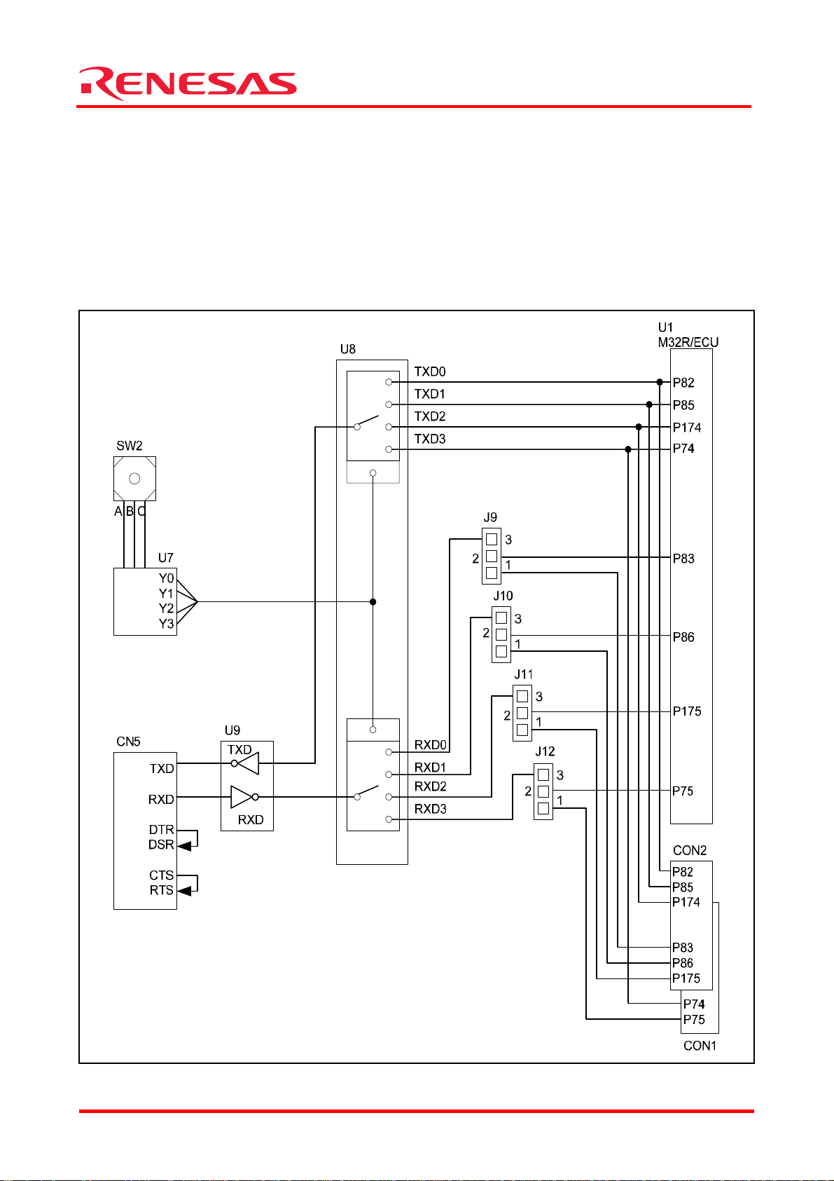
32176 Group
Starter Kit User’s Manual M3A-2152
2.4 Serial I/O Interface
The evaluation board is interfaced to the host PC (DOS/V) through its RS-232C by using SIO of the
M32R/ECU.
Of the RS-232C control signals, only TXD and RXD are used for connection to the host PC (DOS/V).
The unused CTS and RTS are directly-coupled to configure a loop-back. The unused DSR and DTR
also are configured in a similar manner. The serial I/O interface is configured in such a way that
only one serial I/O channel can be used at a time.
Any of the four channels 0–3 can be selected using a rotary switch.
Figure 2.4 Serial I/O Interface
REJ10B0224-0300/Rev.3.00 Jan. 2007 Page 49 of 82
Page 56

Starter Kit User’s Manual M3A-2152
Table 2.5 Channel Selection by a Rotary Switch
Rotary switch position SIO Selected channel
0 SIO0
1 SIO1
2 SIO2
3 SIO3
Table 2.6 Serial I/O Interface (Jumper)
Name Default Condition Description
{
J9
{
J10
{
J11
{
J12
Shorted
between 1–2
Shorted
between 2–3
Shorted
between 1–2
Shorted
between 2–3
Shorted
between 1–2
Shorted
between 2–3
Shorted
between 1–2
Shorted
between 2–3
Connects P83/RXD0 to the extension connector (CON2)
Uses the RXD0 function in RS-232C
Connects P86/RXD1 to the extension connector (CON2)
Uses the RXD1 function in RS-232C
Connects P175/RXD2 to the extension connector (CON2)
Uses the RXD2 function in RS-232C
Connects P75/RXD3 to the extension connector (CON1)
Uses the RXD3 function in RS-232C
Table 2.7 RS-232C Connector Pin Assignments
Connector Name Pin No Signal Name Description
32176 Group
1 DCD Unused
2 RXD Received data
3 TXD Transmitted data
4 DTR Connects to the DSR pin
CN5
5 SG Ground
6 DSR Connects to the DTR pin
7 RTS Connects to the CTS pin
8 CTS Connects to the RTS pin
9 RI Unused
REJ10B0224-0300/Rev.3.00 Jan. 2007 Page 50 of 82
Page 57

32176 Group
Starter Kit User’s Manual M3A-2152
2.5 Oscillator Circuit
The oscillator circuit can be selected from three options by using the jumper J1: a surface
mount-type 10 MHz crystal oscillator module, a DIP-type crystal oscillator module or a crystal
resonator.
By default, the surface mount-type 10 MHz crystal oscillator module is selected.
Surface
mount-type
oscillator module
DIP-type
oscillator module
Figure 2.5 Oscillator Circuit
Note: The shaded sections in the above diagram have only patterns available. When using the resonator Y1, please
be sure to add capacitors (C3, C4) and a resistor (R4).
Table 2.8 Oscillator Circuit Connections (Jumper)
Name Default Condition Description
{
J1
Note: The J1 jumper is shorted by soldering.
between 1–4
between 2–4
between 3–4
X1
X2
Shorted
Shorted
Shorted
OUT
J1
2
1
4
3
R3
Y1
C4
R4
C3
U1
M32R/ECU
XINOUT
XOUT
Outputs a clock from X1 (surface mount-type oscillator module)
Outputs a clock from X2 (DIP-type oscillator module)
Outputs a clock from Y1 (resonator)
REJ10B0224-0300/Rev.3.00 Jan. 2007 Page 51 of 82
Page 58

Starter Kit User’s Manual M3A-2152
2.6 General-purpose Output Port LED Indicators
The LED indicators (L0–L7) are used to indicate t h e status o f the M32R/ECU ports P110–P117.
U1
M32R/ECU
P110
P111
P112
P113
P114
P115
P116
P117
U6
TC74HC540
RA4
L0
L1
L2
L3
L4
L5
L6
L7
Figure 2.6 LED Indicator Block for the General-purpose Output Ports
Table 2.9 LED Indicators of General-purpose Output Ports
LED Name
Corresponding
M32R/ECU Port
ON Condition Color
L0 P110 High Red
VCC
32176 Group
L1 P111 High Red
L2 P112 High Red
L3 P113 High Red
L4 P114 High Green
L5 P115 High Green
L6 P116 High Green
L7 P117 High Green
REJ10B0224-0300/Rev.3.00 Jan. 2007 Page 52 of 82
Page 59

32176 Group
Starter Kit User’s Manual M3A-2152
2.7 General-purpose Input Port Control Circuit
The general-purpose input port control circuit is used to control the status of the M32R/ECU ports
P130–P137 by using toggle switches (S0–S7).
VCC
U1
M32R/ECU
P130
P131
P132
P133
P134
P135
P136
P137
S0
2
S1
2
S2
2
S3
2
S4
2
S5
2
S6
2
S7
2
RA7
1
3
1
3
1
3
1
3
1
3
1
3
1
3
1
3
RA5
Figure 2.7 General-purpose Input Port Control Circuit
Table 2.10 Relationship Between
Toggle Switches and Ports Table 2.11 Toggle Switch Positions
Toggle Switch Name
Corresponding
M32R/ECU Port
S0 P130 Up High
S1 P131 Middle Open
Lever Direction Port Input Level
S2 P132
Down Low
S3 P133
S4 P134
S5 P135
S6 P136
S7 P137
Lever direction
Up Middle
Port input level H Open L
Down
Figure 2.8 Toggle Switch Positions
REJ10B0224-0300/Rev.3.00 Jan. 2007 Page 53 of 82
Page 60

32176 Group
Starter Kit User’s Manual M3A-2152
2.8 Analog Port Input Control Circuit
The analog port input control circuit is used to control the status of the M32R/ECU ports AD0IN0
and AD0IN1 by using VR controls VOL0 and VOL1.
U1
M32R/ECU
AD0IN0
H3
1 2
VOL0
AVCC
AVCC
AD0IN1
H4
1 2
VOL1
Figure 2.9 Analog Port Input Control Circuit
Table 2.12 Analog Port Input Control (Jumper)
Name Default Condition Description
{
H3
{
H4
Shorted
between 1–2
Open
between 1–2
Shorted
between 1–2
Open
between 1–2
Uses VR control (VOL0)
Does not use VR control (VOL0)
Uses VR control (VOL1)
Does not use VR control (VOL1)
Note: The H3 and H4 jumpers are shorted by soldering.
REJ10B0224-0300/Rev.3.00 Jan. 2007 Page 54 of 82
Page 61

32176 Group
Starter Kit User’s Manual M3A-2152
2.9 CAN Interface
The evaluation board is interfaced to a CAN-mounted system by using the internal CAN functions
of the M32R/ECU.
Note: TX7, TX8, TX9, TX10, TX11, TX12, TX13 and TX15 are not mounted but they only have patterns available.
Figure 2.10 Interface with a CAN-mounted System
REJ10B0224-0300/Rev.3.00 Jan. 2007 Page 55 of 82
Page 62

Starter Kit User’s Manual M3A-2152
Table 2.13 CAN Connector Pin Assignments
Connector Name Pin No Signal Name Description
1 CANH1 High-level CAN0 input/output port
2 CANL1 Low-level CAN0 input/output port
3 CANH2 High-level CAN1 input/output port
32176 Group
CN4
4 CANL2 Low-level CAN1 input/output port
5 GND Ground
6 — Free pin
7 GND Ground
8 — Free pin
(1) How to connect the CAN connector
The jumpers J13 and J14 allow selecting the destinations to which the CAN communication pins
(CTX, CRX) are connected.
Table 2.14 Jumper Usage Conditions (J13 and J14)
Name Default Condition Description
{
J13
{
J14
Shorted
between 1–2
Shorted
between 2–3
Shorted
between 1–2
Shorted
between 2–3
Connects P221 to the extension connector (CON1)
Uses the CRX0 function
Connects P77 to the extension connector (CON1)
Uses the CRX1 function
(2) How to select the terminating resistor connection
The jumpers J5 and J7 allow the terminating resistors to be used in the CAN transmission path
Table 2.15 Selecting the Terminating Resistor Connection (J5 and J7)
Name Default Condition Description
{
J5
{
J7
Note: The jumpers J5 and J7 are shorted by soldering.
Shorted
between 1–2
Open
between 1–2
Shorted
between 1–2
Open
between 1–2
Uses the CAN0 terminating resistor mounted on-board
Does not use the CAN0 terminating resistor mounted on-board
Uses the CAN1 terminating resistor mounted on-board
Does not use the CAN1 terminating resistor mounted on-board
REJ10B0224-0300/Rev.3.00 Jan. 2007 Page 56 of 82
Page 63

32176 Group
Starter Kit User’s Manual M3A-2152
2.10 JTAG Peripheral Circuit
The evaluation board comes standard with a connector for Renesas SDI. This connector consists of
the 2.54-mm contact pitch XG4C-1034 made by Omron Corporation.
XCN1
1
2
3
4
5
6
7
8
9
10
Figure 2.11 JTAG/NBD Interface
Table 2.16 JTAG Connector Pin Assignments
Connector Name Pin No Signal Name Description
VCC
U1
M32R/ECU
JTCK
JTDI
JTDO
JTMS
JTRST
RESET
1 JTCK Test clock
2 GND Ground
3 JTDI Test data input
4 JTDO Test data output
5 JTMS Test mode select
XCN1
6 JTRST Test reset
7 JDBI Break request
8 VCC Power supply
9 JVCC User system power supply monitor
10 RESET Reset
REJ10B0224-0300/Rev.3.00 Jan. 2007 Page 57 of 82
Page 64

Starter Kit User’s Manual M3A-2152
3. Reference Data
3.1 Jumper and Test Pin Lists
3.1.1 Jumpers
Table 3.1 Jumper List
Jumper No. Default Description
J1 Shorted between 1–4 Outputs a clock from X1 (surface mount-type oscillator module)
J2 Shorted between 1–2 Sets MOD1 to 0
J4 Shorted between 1–2
J5 Shorted between 1–2 Uses the CAN0 terminating resistor mounted on-board
J6 Shorted between 1–2 Enables reprogramming the M32R/ECU’s internal flash
J7 Shorted between 1–2 Uses the CAN1 terminating resistor mounted on-board
MOD0 is controled by EXTMOD0 or is set to 0 unless it is controled
by EXTMOD0
32176 Group
J9 Shorted between 1–2 Connects P83/RXD0 to the extension connector (CON2)
J10 Shorted between 1–2 Connects P86/RXD1 to the extension connector (CON2)
J11 Shorted between 1–2 Connects P175/RXD2 to the extension connector (CON2)
J12 Shorted between 1–2 Connects P75/RXD3 to the extension connector (CON1)
J13 Shorted between 1–2 Connects P221 to the extension connector (CON1)
J14 Shorted between 1–2 Connects P77 to the extension connector (CON1)
H1 Shorted between 1–2 Power supply from VCCE (CN2)
H3 Shorted between 1–2 Uses the VR control (VOL0)
H4 Shorted between 1–2 Uses the VR control (VOL1)
H6 Shorted between 1–2 Power supply from AVCC
3.1.2 Test Pins
Table 3.2 List of Test Pins
Test Pin No. Signal Name Test Pin No. Signal Name
TX1 AVCC TX10 CANL0
TX2 GND TX11 CANH1
TX3 GND TX12 CTX1
TX4 VCCE TX13 CRX1
TX6 MOD0 TX14 FP
TX7 CANH0 TX15 CANL21
TX8 CTX0 TX16 TXD1
TX9 CRX0 TX18 VREF0
REJ10B0224-0300/Rev.3.00 Jan. 2007 Page 58 of 82
Page 65

32176 Group
Starter Kit User’s Manual M3A-2152
3.2 Extension Connectors CON1 and CON2
3.2.1 Pin Assignments of the Extension Connector CON1
Bard edge
CON1
678 66 54 42 30 18114 102 90
Figure 3.1 CON1 Connector Pin Assignments (View from Side of Mounted Items)
Table 3.3 CON1 Connector Pin Assignments
Pin No.
Signal
Name
Pin No.
Signal
Name
Pin No.
Signal
Name
Pin No.
1 AVCC 31 NC 61 VCCE 91 NC
2 GND 32 NC 62 GND 92 P124
3 VCCE 33 GND 63 AVCC0 93 P125
4 P150 34 NC 64 VREF0 94 P126
5 NC 35 RESET 65 AD0IN0 95 P127
6 NC 36 NC 66 AD0IN1 96 NC
7 P153 37 NC 67 AD0IN2 97 NC
8 NC 38 NC 68 AD0IN3 98 NC
9 NC 39 NC 69 AD0IN4 99 NC
10 NC 40 NC 70 AD0IN5 100 NC
11 NC 41 NC 71 AD0IN6 101 NC
12 NC 42 NC 72 AD0IN7 102 NC
13 NC 43 NC 73 GND 103 NC
14 NC 44 P74 74 AD0IN8 104 NC
15 NC 45 P75 75 AD0IN9 105 NC
16 P130 46 P76 76 AD0IN10 106 NC
17 P131 47 P77 77 AD0IN11 107 NC
18 P132 48 NC 78 AD0IN12 108 NC
19 P133 49 NC 79 AD0IN13 109 NC
20 P134 50 NC 80 AD0IN14 110 NC
21 P135 51 NC 81 AD0IN15 111 NC
22 P136 52 NC 82 P61 112 P110
23 P137 53 P100 83 P62 113 P111
24 P220 54 P101 84 P63 114 P112
25 P221 55 P102 85 SBI 115 P113
26 NC 56 P103 86 GND 116 P114
27 NC 57 P104 87 GND 117 P115
28 VCCE 58 P105 88 GND 118 P116
29 GND 59 P106 89 VCCE 119 P117
30 NC 60 P107 90 GND 120 P97
Note: NC denotes “Not Connected.”
1st pin
3rd pin1284 72 60 48 36 24120 108 96
Signal
Name
REJ10B0224-0300/Rev.3.00 Jan. 2007 Page 59 of 82
Page 66

32176 Group
Starter Kit User’s Manual M3A-2152
3.2.2 Pin Assignments of the Extension Connector CON2
Board edge
126198 186 174 162 150 138234 222 210
132204 192 180 168 156 144240 228 216
Figure 3.2 CON2 Connector Pin Assignments (View from Side of Mounted Items)
Table 3.4 CON2 Connector Pin Assignments
Pin No.
Signal
Name
Pin No.
Signal
Name
Pin No.
Signal
Name
Pin No.
1 (121) P96 31 (151) NC 61 (181) P174 91 (211) P1
2 (122) P95 32 (152) NC 62 (182) P175 92 (212) P0
3 (123) P94 33 (153) NC 63 (183) NC 93 (213) GND
4 (124) P93 34 (154) VCCE 64 (184) NC 94 (214) P73
5 (125) VCCE 35 (155) GND 65 (185) NC 95 (215) P72
6 (126) GND 36 (156) NC 66 (186) NC 96 (216) P71
7 (127) NC 37 (157) NC 67 (187) FP 97 (217) P70
8 (128) P27 38 (158) NC 68 (188) MOD0 98 (218) P43
9 (129) P26 39 (159) NC 69 (189) NC 99 (219) P42
10 (130) P25 40 (160) NC 70 (190) NC 100 (220) P41
11 (131) P24 41 (161) NC 71 (191) GND 101 (221) NC
12 (132) P23 42 (162) NC 72 (192) NC 102 (222) GND
13 (133) P22 43 (163) NC 73 (193) NC 103 (223) NC
14 (134) P21 44 (164) NC 74 (194) GND 104 (224) NC
15 (135) P20 45 (165) NC 75 (195) VCCE 105 (225) NC
16 (136) GND 46 (166) NC 76 (196) NC 106 (226) NC
17 (137) P37 47 (167) NC 77 (197) P17 107 (227) NC
18 (138) P36 48 (168) NC 78 (198) P16 108 (228) NC
19 (139) P35 49 (169) NC 79 (199) P15 109 (229) NC
20 (140) P34 50 (170) NC 80 (200) P14 110 (230) NC
21 (141) P33 51 (171) NC 81 (201) P13 111 (231) GND
22 (142) P32 52 (172) NC 82 (202) P12 112 (232) NC
23 (143) P31 53 (173) NC 83 (203) P11 113 (233) NC
24 (144) P30 54 (174) NC 84 (204) P10 114 (234) NC
25 (145) P47 55 (175) P87 85 (205) P7 115 (235) NC
26 (146) P46 56 (176) P86 86 (206) P6 116 (236) NC
27 (147) P225 57 (177) P85 87 (207) P5 117 (237) NC
28 (148) NC 58 (178) P84 88 (208) P4 118 (238) NC
29 (149) P45 59 (179) P83 89 (209) P3 119 (239) NC
30 (150) P44 60 (180) P82 90 (210) P2 120 (240) NC
Note: NC denotes “Not Connected.”
1st pin
3rd pin
CON2
Signal
Name
REJ10B0224-0300/Rev.3.00 Jan. 2007 Page 60 of 82
Page 67

Starter Kit User’s Manual M3A-2152
3.3 Modular Cord for CAN
(1) External view
Figure 3.3 External View
(2) CC1 and CC2 connections
Table 3.5 Connection Table
CN1 CN2
Pin No. Pin Name Pin Name Pin No.
1 — NC 1
32176 Group
2 CANL (blue) CANL 2
3 — GND 3
4 CANH (white) NC 4
5 GND (black) NC 5
6 — NC 6
CANH 7
NC 8
NC 9
REJ10B0224-0300/Rev.3.00 Jan. 2007 Page 61 of 82
Page 68

3.4 Connection Diagram
A connection diagram is provided in follo wing pages for your reference.
32176 Group
Starter Kit User’s Manual M3A-2152
REJ10B0224-0300/Rev.3.00 Jan. 2007 Page 62 of 82
Page 69

4
REJ10B0224-0300/Rev.3.00 Jan. 2007 Page 63 of 82
ECCV ICCV
R
R
EPM
EPM
2M
2M
1
3
2
U
U
J
J
A
F
F
7PC
7PC
u10.0
u10.0
67123Mroftrohs2-1:1M
2
4
I
DNG
C
C
V
T
H
U
1X
1X
N
I
O
1
3
k
c
ECCV
1
1M1M
2
B
4
4
F
F
u
u
P
P
1.
1.
C
C
0
0
7V
751EC
C
olC
EDD7V
2
)ne
)ne
pO
pO
(
(
F
F
p03
p03
4C
4C
)nepo(ZTM01
Fu
Fu
8PC
8PC
10
10
.
.
0
0
z
z
HM
HM
1
01-L
01-L
S1
S1
570SD
570SD
2
CCV
D
NG
TU
2X
2X
O
3
R
R
EP
EP
MU
MU
J
J
1J
1J
2
143
NI7X
)nepo(ZTM01
)
)
n
n
epO(
epO(
-
SA
SA
1Y
1Y
)nepo(
)nepo(
zH
zH
M01
M01
1M
1M
3
3
R
R
F
F
3C
3C
C
C
p
p
0
0
3
3
)
)
nepO(0
nepO(0
4R
4R
TUO7X
F
F
u1
u1
9PC
9PC
.
.
0
0
1
0.1
0.1
0.1
ve
ve
ve
R
R
R
61
fo
fo
fo
1
1
te
te
te
A
e
e
e
8
8
8
h
h
h
S
S
S
04
04
04
)kcolBP
)kcolBP
)kcolBP
03KD
03KD
03KD
ONGWD
ONGWD
ONGWD
F
F
F
V4F67123MUCM(
4F67123MUCM(
4F67123MUCM(
10G2512-A3M
10G2512-A3M
10G2512-A3M
>e
>e
>e
d
d
d
oCeg
oCeg
oCeg
ed
ed
ed
a
a
a
o
o
o
C<
C<
C<
CEG
CEG
CEG
A
A
A
C
C
C
e
e
e
3A
3A
3A
la
la
la
e
e
e
ziS
ziS
ziS
c
c
c
S
S
S
B
3002
,0
3,yaM
E
C
CV
REPM
REPM
1
3
2
2
2
J
J
U
1K
E
C
73,
6,
C
D
E
C
C
E
V
3
]5
22
]74:14[P273,6
:
02
2
[
P
2
522P23
7
,2
24P23
14P23
0CCVCX7E,2
1CC
D
DVCX7E,2
V
C
X
531
E
2
21A/
ELB/WLB/14P
5
22
P
137
61
73
132
95
65
20
0
F
ER
V
1
1
2
U
U
4
3
3
Fu1.0
Fu1.0
P
P
C
C
2
2
F
F
u1
u1
P
P
C
C
.
.
0
0
1
1
F
F
u1
u1
P
P
C
C
.
.
0
0
0
FERV
7,
6
34P23
631
EHB/WHB/24P
VCCE
VCCE
VCCE
VCCE
0
CC
V
A
3
4
0N
I0
D
A
23
C
C
V
A
44P23
931
041
0
DR/34P
S
C/44P
EXCVCC
EXCVCC
EXCVDD
0
1
N
N
I
I0D
0DA
A
5
4
4
4
1
N
I0
D
A
23
]73:03
[
P273,6
74
54P
64P23
1
03
P
3
2
23
3
P2
P2
3
3
241
141
341
9
8
41A/7
51A/03
3
6
1SC/54
1A
1
A/1
/6
4
3
4P
P
P
P
P
3
5N
2
6NI0D
4
7NI0D
NI
NI0D
N
I0D
I0D
0DA
A
A
A
A
A
15
64
94
7
0
84
5
4
7NI0
5
4
6NI0DA23
NI0DA
NI
2
3
0
N
N
I0
I
D
D
0DA2
A
A
D
2
23
23
3
A
2
3
3
]
51
:
0
[N
I0
D
A
23
7
,
6,
4
,
6
]
72
:
0
2[P273
63P23
4
7
53
3P23
3
33P
23P23
01
2
5
8NI0DA
2
3
02
12
P23
P
23
P2
P2
2
3
3
3
61
31
4
11
7
81A/3
1A/23P
3P
9
8
NI
N
I
0D
0
D
A
A
35
9
NI0
D
A23
7
21
51
1
1
42A/
91
12A/63P
22A
0
32A/02P
2
A/53P
A/4
/7
1
3P
2P
3
P
2
11NI
5
01
3
41
1NI0D
1
1NI0
0S
N
N
NI0DA
I
I
0D
0D
0DA
S
DA
V
A
A
A
A
75
4
0
85
5
95
65
5
6
5
51N
2
31NI0DA23
4
1
1
0
1
NI
NI
I
1
1N
0DA
0
0
N
I
I0
D
D
0
A
A
D
D
2
2
23
3
3
A2
A
23
3
5
5
F
F
u1
u1
P
P
C
C
.
.
0
0
6
6
F
F
u
u
P
P
1.
1.
C
C
0
0
,6
]7:0[
P
273
72P23
5
42
62P
2P2
22P2
32
P23
23
3
P
2
3
3
91
4
2
3
81
2
2
2
52
72
62A/
82A/52P
A/
A
/42P
22P
32
P
0N
3N
I
I
T
T/35
/0
51
1
P
P
331
43
4
2
1
1
0
3
0
5
3
51P2
1
1
P
P
23
2
3
3
]
]
75
731:031[P23
1
:051
[
P
23
7,
7,
6
6,
4
4P23
6P2
5
P
3P23
0P23
2P23
1
2
3
3
P23
8
6
92
52
0
9
2
3A
A/62P
/72P
6
7
81N
1
1
NI
NI
I
T/231
T
T/
/
131
03
1P
P
P
52
621
1
1
2
3
3
1P23
1
P
23
2
72
03
13
2
2
3
1BD
2BD
5BD/5
0BD/00P
4BD/40P
3B
D
/2
/3
/
10P
0
0
0
P
P
P
2
91NIT/
32N
02NI
12
2
NIT
NI
I
T
T/
T
/43
/
/63
7
531
33
31P
1P
1
1
P
P
P
131
82
91
7
921
0
3
21
1
1
1
731P
4
4
5
6
31P
3
2
31
1
1
33
P2
P
P
1
23
2
2
23
3
3
3
P2
3
]
72
1:
421[P237,6
C
V
1R1K1R
]7
1
:
01
[P273,6
5
71P23
61P23
41
7P23
3
3
6
BD
/60P
0K
LC
T/42
1
P
0
21
5
21P23
1
01P2
11
2
3
P
P23
1
1P
2
3
P2
P
2
23
3
3
3
9
4
63
5
73
04
83
3
3
3
0
31BD/51P
21BD/41P
7B
D/
7
0P
1
2
KLCT
KLC
T/
/
5
621
21P
P
121
6
72
2
1
1
P
P
2
23
3
41BD/61P
1
9BD/11P
8BD/01P
1
1
BD/
B
D/31
2
1
P
P
3
KL
1
4
0
2
3O
C
O
O
O
O
T
T/411P
T/
T
T/72
T
/
/
/
0
11
211P
31
11
1P
1
1
P
P
P
1
0
22
7
89
99
0
01
9
1
1
5
4
11P
11P
0
1
2
31
1
1
1
1
1P23
1P23
1
2
2
3
3
P
P
23
23
]
711:011[P2
37,
6
,
4
7
7
,6
6
]77:
]76
:
0
16
7
[
[P2
P
2
3
3,
46P23
2
36P2
17P23
16
07P23
6
P
P23
23
3
57
87
1
4
5
1B
D/
7
1
P
5
6
O
O
T
T/
/51
6
11
1
P
P
2
30
0
1
1
61
1
P
23
9
77
6
47
7
7
I
3
16P
26
RW/KLCB/07P
BS/4
6
P
P
6
P
0
1
9
7
8
1
1
O
O
OT
O
O
T/
T
T/
T
/1
/
/3
7
001
201P
0
11P
01
1P
P
P
411
401
5
6
50
70
11
01
1
1
711P
4
0
1P
3
1
20
0
01P
0
0
1P
1
1
23
2
3
P
P
2
2
23
2
3
3
3
]
701
:
001[P237,
6
27P
2
3
TI
A
W/
1
7P
2
1
O
T/
401
P
5
01P
2
3
5
4
67P23
7
7
37P
P23
P
2
3
2
3
3
0
28
1
4
8
8
8
8
3DXT/DXT
3DXR/DXRDT
K
Q
CAH/37
ER
H/27P
P
D
T
R
R
/47
/57P
P
5
3
41
1
1
O
O
O
T/
T/
T
/6
701P
501
01
P
P
7
6
8
0
11
11
11
9
7
60
0
7
1
9P
1
P2
P2
2
3
3
3
]
7
9:
3
9[P
2
37
,
6
7
6
,5
]
7
8:2
8
[
P
2
3,
77P23
28P23
58
1
1
XRC/
X
T
C/
K
K
LC
C
AD
DTR/
T
R
/6
7
7
7
P
P
0
9
8
1OT
2O
1
O
T/
T/
/59P
79P
69
P
88
9
8
5
49P
6
9P
9P
2
2
2
3
3
3
,6
,
5
]771:271[P273
68
48P23
7
58P23
8
471P23
3
P
P23
8P
23
2
3
76
86
1
07
96
66
7
1D
0DX
1DX
0DXR/38P
1OKLCS/1
OKLCS
XT
T
R
/28P
/5
/6
/
8
8P
0I
P
I
KLCS
KL
C
/
S
/78P
4
8
P
7
61
1
O
O
T
T/
/
49
39
P
P
7
68
8
3
9P
2
3
CCVCSOCX7E,2
TESE7R,6,2
571P
2
3
801
36
1
46
9
7
2D
2DXR/571
TNCV
TESER
ED
X
D
T
V
/47
1P
P
49
3
6
4
5
TUOX
S
N
CCV-CSOCX
IX
S
V-CSO
E
M32R/ECU #4NL (M32176F4VFP)
0
0XTC/0
X
R
C/1
T
S
SR
O
KC
I
22
22
D
M
D
TJ
TJ
T
TJ
T
J
0
901
11
SMTJ
KC
T
J
7
7
,2
,
2
P
P
J
2
4
3
11
1
1
41
1
1
1
1
0
1
22P
22P
2
2
3
3
]
522:
TS
ODTJ7,2
I
0
DT
RT
2
2
[
J
J7
P
2
7
37,
,2
,2
6
,
3
U
J
J
1DO7M
,
3
2DO7M,2
0DO7M
P7F,3
321
29
39
0
1DOM
2DOM
PF
D
OM
GND
138
GND
96
GND
72
GND
62
GND
21
P
P
FT
FT
4
4
F
F
6
6
7
7
1
1
2
2
3
3
M
M
C
D
E
5 5
4
3 3
2
1
Page 70

4
REJ10B0224-0300/Rev.3.00 Jan. 2007 Page 64 of 82
TSRTJ7,1
SMTJ7,1
ECCV
11PC
E
D
11PC
Fu1.0
Fu1.0
9
1AR
1AR
8
7
6
K01
K01
4
3
2
10
F/I GATJ
TSRTJ:6
IBDJ:7
CCV:8
1 5
5
876
2
2
A
A
R
R
33
33
123
4
1NCX
1NCX
TESER:01
901
4301-C4GX
4301-C4GX
123456
78
CCVJ:9
KCTJ7,1
IDTJ7,1
ODTJ7,1
2K
2K
6
6
R
R
5
876
3AR333AR
33
123
4
ECCV
10K7R10K
0
7R
9R09R
3U
3U
22K8R22K
8R
TESER
10K
10K
11R
11R
2
NI
PFB
PFB
7
7
5915M
5915M
TUO
dC
5
6
Fu740.07CFu740.0
7C
K1
01RK101R
1
1
S
S
W
W
1WS
1WS
2
TESER7,6,1
2
)4=DNG,7=CCV(
3
3
HA51-BB
HA51-BB
1
0.1
0.1
0.1
veR
veR
veR
62
fo
fo
fo
2
2
teehS
teehS
teehS
E
80403KD
80403KD
80403KD
)kcolB
)kcolB
)kcolB
lortn
lortn
lortn
ON GWD
ON GWD
ON GWD
o
o
o
10G2512-A3M
10G2512-A3M
10G2512-A3M
C teseR
C teseR
C teseR
>e
>e
>e
d
d
d
oC eg
oC eg
oC eg
/
/
/
edoC EGAC
edoC EGAC
edoC EGAC
rewoP(
rewoP(
rewoP(
a
a
a
C<
C<
C<
elacS
elacS
elacS
3A
3A
3A
eziS
eziS
eziS
D
3002 ,03 ,yaM
KCTJ:1
C
NIP TSET
NIP TSET
3
3
X
X
T
T
NIP TSET
NIP TSET
2
2
X
X
T
T
C
C
VA
B
N
N
I
I
P
P
T
T
1
1
S
S
X
X
E
E
T
T
T
T
1H
1H
2
3
y
A
l
1
1
pp
NC
NC
1
2
u
s
r
ew
o
p
C
CV
A
SMTJ:5
IDTJ:3
O
DTJ:4
DNG:2
DDVCXE7,1
CCVECCV
ICCV
+
+
Fu01
Fu01
31PC
31PC
NIP TSET
NIP TSET
5
5
X
X
T
T
+
+
Fu01
Fu01
6C
3.3-MC6801TL2U3.3-MC6801TL
837AM1D837AM
ECCV
+
+
F
F
21PC
21PC
u01
u01
1D
2U
+
+
Fu01
Fu01
0
0
1PC
1PC
N
N
IP
IP
TS
TS
4
4
XT
XT
ET
ET
12
R
R
E
E
PM
PM
1
UJ
UJ
y
A
A
l
-
H
H
X
X
-
B2
B2
S
S
2
2
pp
NC
NC
1
u
s
r
ew
o
p
E
CC
3J3J
TU11
TU11
2
2
-
L
L
1DEL
1DEL
MS
1K
1K
5
5
R
R
A
A
-
H
H
X
X
-
-
2
B2
B2
S
S
MS
6C
2
TUOV
GND
1
N
IV
3
+
+
Fu
Fu
5C
5C
0
0
1
1
2D
2D
8
8
37AM
37AM
V
4
REPMUJ2HREPMUJ
2H
2
1
3
yl
3
3
p
N
N
2
1
pu
C
C
s
r
e
wo
p
I
C
C
V
3 3
3M3M
1 2
A
A
-HX-
-HXB
B
2S
2S
0CCVCXE7,1
1XC
1XC
Fu1
Fu1
4M4M
1 2
1CCVCXE7,1
2XC
2XC
Fu1
Fu1
12
5M5M
CCVCSOCXE7,1
3XC
3XC
Fu1
Fu1
6M6M
1 2
.
pa
C
e
n
il
re
w
oP
2 2
2DOM7,1
4XC
4XC
Fu1
Fu1
0
21R021R
12
7M7M
71PC
71PC
Fu74
Fu74
+
+
6
6
Fu74
Fu74
1PC
1PC
I
+
+
CCV
5
5
Fu74
Fu74
1PC
1PC
+
+
41PC
41PC
Fu74
Fu74
E
+
+
CCV
67123M rof nepo 2-1 :6-
5XC
5XC
Fu1.0
Fu1.0
C
2
M,3J
B
A
1
Page 71

0.1
REJ10B0224-0300/Rev.3.00 Jan. 2007 Page 65 of 82
0.1
0.1
veR
veR
veR
63
fo
fo
fo
3
)kcolB tceleS PF / 0DOM /
)kcolB tceleS PF / 0DOM /
)kcolB tceleS PF / 0DOM /
E
7,10DOM
7,1PF
NIP TSET
NIP TSET
NIP TSET
6XT
6XT
+
+
Fu2.2
Fu2.2
91PC
tceles 0DOM UCE/R23M
91PC
NIP TSET
4
4
1
1
XT
XT
W/S tceles
+
+
Fu2.2
Fu2.2
42PC
42PC
10G2512-A3M
10G2512-A3M
10G2512-A3M
F
F
F
I
I
I
NAC(
NAC(
NAC(
3
teehS
teehS
teehS
E
8
8
8
0
0
0
403KD
403KD
403KD
ON GWD
ON GWD
ON GWD
>edoC egaC<
>edoC egaC<
>edoC egaC<
edoC EGAC
edoC EGAC
edoC EGAC
02PC
02PC
Fp022
Fp022
REPMUJ4JREPMUJ
2
4J
1
D
W/
S
C
B
3
10K
ECCV
7,6,10XTC
0XTC
NIP TSET
NIP TSET
9XT
9XT
NIP TSET
NIP TSET
8XT
8XT
F
/I
4U
NA
C
NIP T
NIP T
7
7
S
S
X
X
ET
ET
T
T
10K
41R
41R
0DOMTXE6
60XRC
0
XR
C
ECCV
12PC
12PC
Fu1.0
Fu1.0
3
1
2
4
DXT
CCV
DXR
DNG
T052C28ACP4UT052C28ACP
LNAC
HNAC
FERV
SR
6
7
8
81
81
P
P
C
C
12
5
0
31R031R
5J
REPMUJ5JREPMUJ
)nepO(Fu1.0
)nepO(Fu1.0
NIP TSE
NIP TSE
01X
01X
T
T
T
T
120
120
5
5
1R
1R
)nep
)nep
O
O
(Fu1.0
(Fu1.0
2
2
2
2
PC
PC
PF
UC
E
/
R2
3
M
10K
10K
ECCV
61R
61R
6
1XTC
1
XTC
NIP TSET
NIP TSET
31XT
31XT
NIP TSET
NIP TSET
21XT
21XT
F/I NAC
5U
NIP TS
NIP TS
11XT
11XT
ET
ET
52PC
52PC
Fp022
Fp022
REPMUJ6JREPMUJ
2
1
3
6J
PFTXE6
61XRC
1XRC
ECCV
62PC
62PC
Fu1.0
Fu1.0
1
3
2
4
DXT
CCV
DXR
DNG
T052C28ACP5UT052C28ACP
HNAC
LNAC
FERV
SR
6
8
5
7
0
0
7
7
1R
1R
7J
12
REPMUJ7JREPMUJ
)nepO(Fu1.0
)nepO(Fu1.0
3
3
2PC
2PC
NIP TSET
NIP TSET
51X
51X
T
T
120
120
81R
81R
)nep
)nep
O
O
(Fu
(Fu
72PC
72PC
1
1
.0
.0
trohS 2-1:
t
l
u
afeD:7J,6J
,
5
J
,4J
elacS
elacS
elacS
3A
3A
3A
eziS
eziS
eziS
3002 ,03 ,yaM
D
C
B
1
2LNAC
1
8
8
021-AER2
021-AER2
4NC
4NC
2
5
8
3
1
6
4
7
M
A
4 4
M
T
T
3 3
2HNAC:3
HNAC:1
L
D
NA
C
:2
DN
N
G
G:
:7
:6
:4
:8
5
2 2
A
1 1
Page 72

4
REJ10B0224-0300/Rev.3.00 Jan. 2007 Page 66 of 82
E
131P237,6,1
231P237,6,1
031P237,6,1
V2J31-A0SV2J31-A
V2J31-A1SV2J31-A
2
2
0S
1
D
ECCV
K
K
001
001
7AR
7AR
10
3
9
8
7
6
4
3
2
1 5
2S
1S
1
3
331P237,6,1
V2J31-A2SV2J31-A
2
1
3
V2J31-A4SV2J31-A
V2J31-A3SV2J31-A
2
4S
3S
1
3
531P237,6,1
431P237,6,1
V2J31-A6SV2J31-A
V2J31-A5SV2J31-A
2
2
6S
5S
1
3
1
3
731P237,6,1
631P237,6,1
V2J31-A7SV2J31-A
2
2
7S
1
1
3
3
K001
K001
5AR
5AR
9
8
7
6
4
3
2
10
15
1
0.1
0.1
0.1
veR
veR
veR
64
fo
fo
fo
4
4
teehS
teehS
teehS
E
80403KD
80403KD
80403KD
)kcolB lortnoC hcti
)kcolB lortnoC hcti
)kcolB lortnoC hcti
ON GWD
ON GWD
ON GWD
10G2512-A3M
10G2512-A3M
10G2512-A3M
>e
>e
>e
d
d
d
oC eg
oC eg
oC eg
w
w
w
edoC EGAC
edoC EGAC
edoC EGAC
S / DEL(
S / DEL(
S / DEL(
a
a
a
C<
C<
C<
elacS
elacS
elacS
3A
3A
3A
eziS
eziS
eziS
D
3002 ,03 ,yaM
C
9
4ARK14AR
8
7
6
4
K1
3
2
10
1 5
1LTU112-LMS 1LTU112-LMS
0LTU112-LMS 0LTU112-LMS
2LTU112-LMS 2LTU112-LMS
4LT
3LTU112-LMS 3LTU112-LMS
U
112-LMS 4LTU112-LMS
6LT
5LT
U
112-LMS 5LTU112-LMS
7LTU112-LMS 7LTU112-LMS
U
112-LMS 6LTU112-LMS
C
trohS
0
N
E
CCV
B
A
51
61
1Y812Y713Y
5Y416Y317Y218Y
4Y
6U
6U
5A
1A22A33A44A
6A77A88A
5
6
411
111
011
211
311
P
P
P
P
P
23
23
23
23
23
7
7
7
7
7
,6,1
,6,1
,6,1
,6,1
,6,1
Fu
Fu
82
82
1
1
P
P
.0
.0
C
C
11
02
01
FA
FA
04
04
CCV
DNG
5
5
CH
CH
4
4
7CT
7CT
1G12G
91
9
K
K
001
001
6AR
6AR
9
8
7
6
4
3
2
10
15
5
71
61
11P
1
1
P237,
P237,6,1
237
,6,1
6
,1
CCVA
I
0DA
2
37,6,1
REPMUJ3HREPMUJ
12
3H
6
6
2B0
2B0
1
1
0LOV
0LOV
11K
11K
9
9
0KR
0KR
1NI0
D
A237,6,1
12
4H
4H
6
6
2B0
2B0
1
1
1
1
11K
11K
L
L
9
9
O
O
0KR
0KR
V
V
21
:t
l
ua
f
eD
:
4H
REP
REP
,
M
M
3H
UJ
UJ
B
A
4
3 3
2 2
1
Page 73

5
REJ10B0224-0300/Rev.3.00 Jan. 2007 Page 67 of 82
0.1
0.1
0.1
veR
veR
veR
6
fo
fo
fo
61DXR
62DXR
60DXR
A
22
0B21B52B63B94B015B416B717B818B129B
CEB
AEB1BEB
DEB
B
K001
K001
8
8
A
A
R
R
9
8
7
6
4
3
2
10
CCV
1 5
8U
1A
2A73A
7A
5A516A
9A
4A
8A
11
02
91
61
32
8
0A
31
73
52
3
4
63DXR
)kc
)kc
)kc
10G2512-A3M
10G2512-A3M
10G2512-A3M
o
o
o
lB FI OI laireS(
lB FI OI laireS(
lB FI OI laireS(
CCV
Fu1.0
Fu1.0
03PC
03PC
,84,63=CCV(
23
34
93
82
04
01B7211B
61B
21B1331B
41B4381B4451B
91B7471B
01A
21A
41
61A
11A
92
62
81A5491A
31A
71A2451A
A
53
33
83
03
14
64
)42,21=DNG
1Q483X23SQ8U1Q483X23SQ
5
5
5
teehS
teehS
teehS
A
8040
8040
8040
3
3
3
KD
KD
KD
ON GWD
ON GWD
ON GWD
>edoC egaC<
>edoC egaC<
>edoC egaC<
edoC EGAC
edoC EGAC
edoC EGAC
elacS
elacS
elacS
3A
3A
3A
eziS
eziS
eziS
B
3002 ,03 ,yaM
0DXT7,6,1
1DXT7,6,1
2DXT7,6,1
3DXT6
C
10K
10K
CCV
91R
91R
CCV
Fu1.0
Fu1.0
13PC
41
21
31
11
51
1Y
3Y
2Y
4Y
0Y
1G
7U
A1B2C
3
6
D
C
C
V
2
5
4
3
A1
A4
A2
A8
2WS
2WS
C
1
CCV
H
H
01
01
RK
RK
-R
-R
D
D
5Y016Y97Y
A2G4B2G
5
7
TF831CHV47CT7UTF831CHV47CT
DNG
CCV
61
8
15
2
3
4
6
7
8
9
F/I C232SR
)51=DNG ,61=CCV(
Fu1.0
Fu1.0
Fu1.09CFu1.0
11C
11C
9C
1
+1
C
CCV
Fu1.0
Fu1.0
92
92
P
P
C
C
10
K001
K001
9
9
A
A
R
R
9U
9U
-
+V
V
2
C
CV
6
Fu1.08CFu1.0
8C
11
01
4
5
3
-1
-2
+2
N
N
I2T
I1T
C
C
C
TUO2T
TUO1T
41
7
Fu1.0
Fu1.0
01C
01C
3
6
8
2
7
1
5
5
N
N
C
C
4
13PC
21
9
TUO2R
TUO1R
E
E
S
S
C2
C2
3
3
23XAM
23XAM
N
NI1
I2R
R
31
8
2
2
1
1
9
5
90-C2MX
90-C2MX
C
D
E
5
4 4
3 3
DXR
D
DX
CD : 1
T
:
:
3
2
ST
RS
RT
D
:
4
S
GS : 5
TC : 8
IR
R
D
:
:
:
6
7
9
2 2
E
1 1
Page 74

2
REJ10B0224-0300/Rev.3.00 Jan. 2007 Page 68 of 82
0.1
0.1
10G2512-A3M
10G2512-A3M
10G2512-A3M
0.1
veR
veR
veR
66
fo
fo
fo
6
6
teehS
teehS
teehS
E
8
8
8
0
0
0
403KD
403KD
403KD
ON GWD
ON GWD
ON GWD
)
)
)
kcolB FI
kcolB FI
kcolB FI
>edoC egaC<
>edoC egaC<
>edoC egaC<
noisn
noisn
noisn
edoC EGAC
edoC EGAC
edoC EGAC
e
e
e
txE(
txE(
txE(
elacS
elacS
elacS
3A
3A
3A
eziS
eziS
eziS
D
3002 ,03 ,yaM
71FERV23
NIP TSE
NIP TSE
7
7
1
1
X
7]51:0[NI1DA23
7,1]71:01[P2
ECCV
37
475767778797081828
2NOC
2NOC
123456789
EC
C
V
49P23
69P23
59
P
23
]79:39[P237,1
3
71
P
23
A39P23
E
S
U
B
C
CV
S
U
BCCV
D
7,1]
7:0[P23
31
21P23
01P23
1
1P2
41P23
61P
51P
P2
3
3
2
2
3
3
01
72P23
42
6
52P23
2
P23
P
23
]7
2
:0
2
[
P237
,
1
3P23
7P23
6P23
5P23
4P
2
3
38
58
6878889809192939495969
48
11
31
41516171819102
21
3
22P23
02P23
12P23
2
73P23
P23
]73:03[P237,1
2P23
1P23
53P23
63P23
7,1]74:14[P23
7,1]77:07[P23
11NI1DA
14P23
24P23
34
17P23
27P23
37P23
0
P
7P2
0P23
23
3
001
101
79
99
89
12
52
32
42
72
829203
22
62
422P23
522P23
23P23
6
7
13P23
3
03P23
4
4P
3
43P23
P23
54P23
P23
23
]74:14[P237,1
]74:14[P237,1
]522:022[P237,3,1
01NI1DA23
9NI1DA23
8NI1DA23
41NI1DA23
51NI1DA23
21NI1DA23
31NI1DA23
201
401
301
13
23
44
P
23
501
334353
7NI1DA23
6NI1DA23
2
3
601
701
801
011
111
211
9
01
93
73
83
63
04
261P23
361P23
761P23
46
661P23
561P23
1P
23
]761:061[P237
22K
22K
02R
02R
X
T
T
T
T
REPMUJ5HREPMUJ
5H
CCVA
1 2
0NI1DA23
2NI1DA23
3
1NI1DA23
N
I1DA
5NI1DA23
4NI1DA23
2
3
SD72.1-S441-1XF
611
021
411511
811
121
612P23
711
546474
8J
8J
12
221
911
3
21
94
84
15
05
012P23
212P23
312P23
112P23
512P23
412P23
76P23
]76:16[P237,1
R
R
E
E
PMUJ
PMUJ
311
14
243444
061P23
161P23
71
2
P23
]712:012[P237
421
521
35
25
5
6
6
6P
P23
23
031
621
821921
721
55657585950616
45
A68P23
4
78P23
8P2
58
3
P
23
231
431
531
631
831
471P23
331
A571P23
36
26
A771P23
671P23
931
7
31
56667686960717
46
371P23
271P23
131
A38P23
28P23
SD72.1-S441-1XF
041
241341
441
141
27
PFTXE3
2DXT7,5,1
]771:271[P237,5,1
trohS 4-1 :9
t
rohS
trohS 2-1:tluaf
31J,21J,11J,01J,9J,8J
M
,8
M
,
t
ro
h
S 2-1:01M,
7
M:
6
71
2
3
M
0DOMTXE3
47P23
21
:t
l
ua
f
eD
eD:6H,5H
:
51
J
,
4
1,
5
3
D
XT
01M 01M
143
2
671P23
37P23
53DXR
9M9M
0DXT7,5,1
NIP TSET
NIP TSET
61XT
61XT
C
B
A
7,4,1]
5
1:
0
[NI
0
DA
2
3
9NI0DA23
8NI0
D
A23
ECCV
374757677787970818283848586878889809192939495969798999
1NOC
1NOC
1
2345678
E
C
C
V
C
C
V
A
]
751:05
1
[
P2
37
,1
7,1]76:16[P23
2
51
41NI0DA23
31NI0DA2
1NI0DA2
1
01NI0DA23
N
I
1
0
N
I
DA
0
DA2
3
1
051P2
5
1P23
3
36P23
2
46P23
16P23
6
2
3
3
3
P23
011121
3141516171819102122232425262728292031323334353637383930414
9
4
5
651P23
7
5
51P
5
1P2
1P2
3
2
5
5
1
1P
2
3
3
3
P
2
2
3
3
0
02
102
2
302
02
P2
3
P
P
P
2
23
23
3
]
30
2
:0
02
[
P
2
3
7
4 4
331P23
231P23
131P
0
31P
2
2
3
3
]7
31
:
03
1
[
P23
7
,4,1
0
XTC7
,
3
,
1
7,1]721:421[P23
7]791:091[P23
721P23
621P23
521P23
421P23
091P23
6
5
431P23
731P
31P
31P
2
2
2
3
3
3
022P23
]
5
22
:
02
2
[
P2
3
7
,
3
,1
7]741:
041[P23
791P23
591P23
491P23
691P23
041P23
291P23
1
391P23
9
1P2
3
001
101
201
301
401
T
ESER7,2,1
A
1
2
3
22P
22P
2
2
P
2
2
2
3
3
3
7,4,1]711:011[P23
511P23
7
541P23
441P23
141P23
3
241P23
4
1P2
3
601
701
801
501
1
0
81P
81P
2
2
3
3
]781:08
1
[
P
237
411P23
641P23
4
1P2
011P2
111P23
211P23
311P23
3
3
901
011
111
211
311
411
511
611
24
34
44546474849405
781P23
581P
4
681P23
81P
A
3
281P23
57P
4
8
1
7
2
2
3
3
P
P
2
2
2
3
3
3
]77:07[P2
37
,1
3 3
1DXT7
,5,1
611P23
711P23
A79P23
021
711
67P
2
3
421
811
911
121
321
221
253545
15
A77P23
]
7
01
:
001[P2
37
,1
50
]78:28[P237,5,1
D
X
R
A38P23
REPMUJ
REPMUJ
REPMUJ9JREPMUJ
1
3
2
01J
01J
38P23
9J
621
921
131
521
721
231
331
821
55
657585
2
301P23
0
1
0
0
0
1P2
1P2
1P2
3
3
3
C
C
VA
531
031
431
631
06
162636
46
95
4
6
7
5
01P
0
01P
0
1
1
P
P
2
2
2
2
3
3
3
3
REPMUJ
REPMUJ
6
6
H
H
1 2
N
N
I
I
P
P
TSET
TSET
81XT
81XT
0
FE
R
V
7,1
52DXR
51DXR
A68P23
REPMUJ
REPMUJ
1
3
3
2
11J
11J
68P23
731
341
831
041
931
141
241
667686
96
07
56
17
0NI0DA23
6
3
1N
4NI0DA
2
5NI0DA23
N
N
N
I0DA
I0DA
I
I0DA
0DA23
2
2
2
2
3
3
3
3
2
A57P23
A571P23
1
1
2
571P23
21J
21J
SD72.1-S44
SD72.1-S44
441
1
1
-1XF
-1XF
27
7
N
I0DA
2
3
]51:0[N
I0DA2
3
7,
4
,1
3
3
1
1
J
J
143
2
B771P23
A771P23
B57P23
REPM
REPM
U
U
J
J
3
1
2
51J
51J
77
57P23
1
P23
8M8M
1
B77P23
A77P23
REPMUJ
REPMUJ
41J
41J
3
1
2
77P23
30
X
RC
A
1
22P
2
3
REPMUJ
REPMUJ
3
1
2
1
22P
2
3
A39P23
B39P23
REPMUJ
REPMUJ
REPMUJ
REPMUJ
3
1
3
2
2
71J
71J
39P23
31XRC
2
3
A79P23
B79P23
R
R
EPMU
EPMU
J
J
61J
61J
1
3
2
79P23
31XTC
11M 11M
2
1
3
69P23
67P
2
3
1 1
C
B
A
Page 75

3.5 Part List
A part list is pro vided following pages for your reference.
32176 Group
Starter Kit User’s Manual M3A-2152
REJ10B0224-0300/Rev.3.00 Jan. 2007 Page 69 of 82
Page 76

REJ10B0224-0300/Rev.3.00 Jan. 2007 Page 70 of 82
Division in charge
Required
M3A-2152G02
Remarks
Supply
Classification
Unit
Q’ty per
Direction
Mounting
Name
Manufacturer
PLL-M3A-2152G02 ( 1 / 4 )
Special note:
Title
No.
Classification
PPL-M3A-2152G02
Part List
Specification)
Part Type Name
(Drawing No.,Product
Part Name Part Specification
Description Part No.
1 M32R/ECU#4NL U1 M32176F4VFP Renesas Socket-mounted 1
2 Microcomputer socket U1 NQPACK144SD, HQPACK144SD Sankyokasei Mounted directly 1
3 Regulator U2 LT1086CM-3.3 Linear Not mounted 0
4 Reset IC U3 M51957BFP Renesas Mounted directly 1
5 CAN driver IC U4,5 PCA82C250T Philips Mounted directly 2
6 LED driver IC U6 TC74HC540AF Toshiba Mounted directly 1
7 Decoder IC U7 TC74VHC138FT Toshiba Mounted directly 1
8 Bus switch IC U8 QS32X384Q1G IDT Mounted directly 1
9 RS232C driver IC U9 MAX3232CSE+ MAXIM Mounted directly 1
Handling
Created Revision
Checked
Item No.
11 Oscillator X2 DOC-49S1(10MHz) Daishinku Not mounted 0
10 Oscillator X1 DS0751SL-10MHz Daishinku Mounted directly 1
12 Resonator Y1 CSA-10MTz(10MHz) Murata Not mounted 0
13 Switch (push type) SW1 BB-15AH(right-angle type) Nihon Kaiheiki Mounted directly 1
14 Operating unit for SW1 For SW1 AT-475 (red color) Nihon Kaiheiki Mounted directly 1
15 Switch S0,1,2,3,4,5,6,7 A-13J2V(right-angle type) Nihon Kaiheiki Mounted directly 8
16 Rotary switch SW2 DR-KR10H(right-angle type) Nihon Kaiheiki Mounted directly 1
Special note:
(1) Blank columns denote the same content as the upper row.
(2) If two or more part type names are written for one part, the upper row has priority.
(3) The asterisk (*) in the item No. column denotes that the rest is blank.
Page 77

Remarks
REJ10B0224-0300/Rev.3.00 Jan. 2007 Page 71 of 82
Supply
Classification
Unit
Q’ty per
Required
Direction
Mounting
Manufacturer Name
PLL-M3A-2152G02 ( 2 / 4 )
Special note:
Specification)
Part Type Name
(Drawing No.,Product
Part Name Part Specification
Description Part No.
17 Connector CN2 S2B-XH-A J.S.T. Mfg. Mounted directly 1
Item No.
18 Connector CN1,3 S2B-XH-A J.S.T. Mfg. Not mounted 0
19 Connector CN4 TM2REA-1208 Hirose Mounted directly 1
20 Connector CN5 XM2C-0912 Omron Mounted directly 1
21 Connector CON1,2 FX1-144S-1.27DS Hirose Mounted directly 2
22 Connector XCN1 XG4C-1034 Omron Mounted directly 1
TX 12,13,14,15,17,18
23 Jumper pin (2 pins) J5,7 FFC-2ASM1B Honda Tsushin Kogyo Jumper fixed 2
24 Jumper pin (2 pins) J3,8 FFC-2ASM1B Honda Tsushin Kogyo Not mounted 0
25 Jumper pin (3 pins) J4,9,10,11,12,13,14 FFC-3ASM1B Honda Tsushin Kogyo Mounted directly 7
26 Jumper pin (3 pins) J2,6,15,16,17 FFC-3ASM1B Honda Tsushin Kogyo Jumper fixed 5
27 Jumper pin (3 pins) H2 FFC-3ASM1B Honda Tsushin Kogyo Not mounted 0
28 Jumper pin (4 pins) J1 FFC-4ASM1B Honda Tsushin Kogyo Jumper fixed 1
29 LED LED1, L0,1,2,3 SML-211UT Rohm Mounted directly 5
30 LED L4,5,6,7 SML-211YT Rohm Mounted directly 4
31 Test pin TX2,3,4,16 ST-1-1 Mac-Eight Mounted directly 4
32 Test pin TX1,5,6,7,8,9,10,11, ST-1-1 Mac-Eight Not mounted 0
Special note:
(2) If two or more part type names are written for one part, the upper row has priority.
(3) The asterisk (*) in the item No. column denotes that the rest is blank.
(1) Blank columns denote the same content as the upper row.
Page 78

Remarks
REJ10B0224-0300/Rev.3.00 Jan. 2007 Page 72 of 82
Supply
Classification
Unit
Q’ty per
Required
Direction
Mounting
Name
Manufacturer
Special note:
PLL-M3A-2152G02 ( 3 / 4 )
Specification)
Part Type Name
(Drawing No.,Product
C1,8,9,10,11, GRM219F11H104ZA01(0.1uF) Murata Mounted directly 19
Part Name Part Specification
Description Part No.
Laminated ceramic
capacitor
33
Item No.
CP1,2,3,4,5,6,9,11,
CP 21,26,28,29,30,31
CP18,22,23,27, GRM219F11H104ZA01(0.1uF) Murata Not mounted 0
Laminated ceramic
capacitor
CP32,33,34,35,36,
34
CX1,2,3,4 GRM219F11E104ZA01(1uF) Murata Mounted directly 4
Laminated ceramic
capacitor
CX5,6,7,8
35
C2, CP20,25 GRM2192P1H221JZA01(220pF) Murata Mounted directly 3
CP7,8 GRM216F11H103ZA01(0.01uF) Murata Mounted directly 2
Laminated ceramic
capacitor
Laminated ceramic
capacitor
Laminated ceramic
36
37
C7 GRM21BB11H473ZA01(0.047uF) Murata Mounted directly 1
C3,4 GRM2192P1H300JZ01(30pF) Murata Not mounted 0
CP19,24 F931V225MBA(2.2uF) Nichicon Mounted directly 2
CP10,12,13 F931D106MBA(10uF) Nichicon Mounted directly 3
capacitor
Laminated ceramic
capacitor
Tantalum electrolytic
capacitor
Tantalum electrolytic
capacitor
Tantalum electrolytic
38
39
40
41
C5,6 F931D106MBA(10uF) Nichicon Not mounted 0
CP14,15,16,17 F931C476MCA(47uF) Nichicon Mounted directly 4
capacitor
Tantalum electrolytic
capacitor
42
43
44 Diode D1,2 MA738 Matsushita Not mounted 0
45 5% resistor array (33 Ω) RA2,3 CN2B4 TBK330J(33Ω) KOA Mounted directly 2
46 5% resistor array (1 KΩ) RA4 CND2B10 TBK102J(1KΩ) KOA Mounted directly 1
47 5% resistor array (10 KΩ) RA1 CND2B10 TBK103J(10KΩ) KOA Mounted directly 1
Special note:
(2) If two or more part type names are written for one part, the upper row has priority.
(3) The asterisk (*) in the item No. column denotes that the rest is blank.
(1) Blank columns denote the same content as the upper row.
Page 79

Remarks
REJ10B0224-0300/Rev.3.00 Jan. 2007 Page 73 of 82
Supply
Classification
Unit
Q’ty per
Required
Direction
Mounting
Manufacturer Name
Special note:
PLL-M3A-2152G02 ( 4 / 4 )
Specification)
Part Type Name
(Drawing No.,Product
Part Name Part Specification
Description Part No.
48 5% resistor array (100 KΩ) RA5,6,7,8,9 CND2B10 TBK101J(100KΩ) KOA Mounted directly 5
Item No.
5% resistor (0 Ω) R4 MCR10EZPJ000(0Ω) Rohm Not mounted 0
49 5% resistor (0 Ω) R9,12,13,17 MCR10EZPJ000(0Ω) Rohm Mounted directly 4
50 5% resistor (120 Ω) R15,18 MCR10EZPJ121(120Ω) Rohm Mounted directly 2
51 5% resistor (1 KΩ) R1,2,5,10 MCR10EZPJ102(1KΩ) Rohm Mounted directly 4
52 5% resistor (2 KΩ) R6 MCR10EZPJ202(2KΩ) Rohm Mounted directly 1
53 5% resistor (22 KΩ) R8,20 MCR10EZPJ223(22KΩ) Rohm Mounted directly 2
54 5% resistor (1 MΩ) R3 MCR10EZPJ105(1MΩ) Rohm Mounted directly 1
DIC208 Honda Tsushin Kogyo Mounted directly 7
Jx compatible jumper
socket
55 1% resistor (10 KΩ) R7,11,14,16,19 MCR10EZPF103(10KΩ) Rohm Mounted directly 5
56 Variable resistor VOL0,1 RK09K1110B26 (right-angle type) ALPS Mounted directly 2
57
58 Pattern only M1,2,3,4,5,6,7,8,9, Not mounted 0
M10,11,12,13,14,
M15,16, H1,3,4,5,6
59 Rubber feet TM-166-3 (black color) 3M Mounted directly 5
60 Board M3A-2152G01 (DK30408) (SHT) - 1
61 Power cable HTD-A4H0043 (SHT) - 1
*
62 CAN cable HTD-A4H0044 (SHT) - 2
(2) If two or more part type names are written for one part, the upper row has priority.
(3) The asterisk (*) in the item No. column denotes that the rest is blank.
Special note:
(1) Blank columns denote the same content as the upper row.
Page 80

Starter Kit User’s Manual M3A-2152
3.6 Pattern Diagram
A pattern diagram for the board is provided in this and followin g pages for your reference.
32176 Group
REJ10B0224-0300/Rev.3.00 Jan. 2007 Page 74 of 82
Page 81

M3A-2152G01
REJ10B0224-0300/Rev.3.00 Jan. 2007 Page 75 of 82
Pattern diagram(1/5)
DATESCALEDIM
03-3-5
APPROVED
/ NTS
DK30435-A
Symbol - print - C
PROJECTION
mm
DESIGNDRAWN CHECKED
RENESAS TECHNOLOGY CORPORATION
IN
3RD ANGLE
DRAWI NG No. PG DATE ITEM DESCRIPTION MATERIAL NUMBER (MATERIAL) VOLUME
Page 82

M3A-2152G01
REJ10B0224-0300/Rev.3.00 Jan. 2007 Page 76 of 82
Pattern diagram (2/5)
DATESCALEDIM
03-3-5
/ NTS
DK30435-A
APPROVED
Pattern 1/4
PROJECTION
mm
DESIGNDRAWN CHECKED
RENESAS TECHNOLOGY CORPORATION
IN
3RD ANGLE
DRA WI NG No. PG DATE ITEM DESCRIPTION M ATERIAL NUMBER (MATERIAL) VO LUME
Page 83

M3A-2152G01
REJ10B0224-0300/Rev.3.00 Jan. 2007 Page 77 of 82
Pattern diagram (3/5)
DATESCALEDIM
03-3-5
/ NTS
DK30435-A
APPROVED
Pattern 2/4
PROJECTION
mm
DESIGNDRAWN CHECKED
RENESAS TECHNOLOGY CORPORATION
IN
3RD ANGLE
DRA WI NG No. PG DATE ITEM DESCRIPTION M ATERIAL NUMBER (MATERIAL) VO LUME
Page 84

M3A-2152G01
REJ10B0224-0300/Rev.3.00 Jan. 2007 Page 78 of 82
Pattern diagram (4/5)
DATESCALEDIM
03-3-5
/ NTS
DK30435-A
APPROVED
Pattern 3/4
PROJECTION
mm
DESIGNDRAWN CHECKED
RENESAS TECHNOLOGY CORPORATION
IN
3RD ANGLE
DRA WI NG No. PG DATE ITEM DESCRIPTION M ATERIAL NUMBER (MATERIAL) VO LUME
Page 85

M3A-2152G01
REJ10B0224-0300/Rev.3.00 Jan. 2007 Page 79 of 82
Pattern diagram (5/5)
DATESCALEDIM
03-3-5
/ NTS
DK30435-A
APPROVED
Pattern 4/4
PROJECTION
mm
DESIGNDRAWN CHECKED
RENESAS TECHNOLOGY CORPORATION
IN
3RD ANGLE
PG DATE ITEM DESCRIPTION MATERIAL NUMBER (MATERIAL) VO LUME
DRA WI NG No.
Page 86

Starter Kit User’s Manual M3A-2152
3.7 Diagram of External Dimension
A diagram of external dimension for the board is provided in following pages for your reference.
32176 Group
REJ10B0224-0300/Rev.3.00 Jan. 2007 Page 80 of 82
Page 87

noisnemid lanretxe fo margaiD
REJ10B0224-0300/Rev.3.00 Jan. 2007 Page 81 of 82
E
MULOV
)
LA
IRETAM
(
R
EB
MUN LAIRETAM
NO
I
TPI
R
C
S
E
D
Remarks
Occupancy
Hole
Diameter
Hole
Symbol
Remarks
Occupancy
Detail table of Through-Hole
Hole
Diameter
Hole
Symbol
shows the hole symbol of the mounting hole.
is 3.2 mounting hole.
Hole Diameter shows the finished diameter of each hole.
[Example]
Mounting hole details
10G2512-A3M
63403KD
mm:NOISNEMID
)1/1(
5-3-30
E
NOITAROPROC YGOLONHCET SASENER
T
A
D
ELA
CS
M
ID
NI
ELGNA DR3
DEVO
R
PPA
STN
/
NGISEDN
mm
N
OI
C
T
EHC
CEJ
O
RP
W
ARD DEK
I
ETAD MET
G
P
.
o
N GNI
W
AR
D
CHANGE
Page 88

Starter Kit User’s Manual M3A-2152
3.8 Description of Board Silk
The color of board silk indicates solder specification when the items on board are mounted.
Table 3.6 Difference in the Color of Board Silk
Color of board silk Solder specification when the items on board are mounted
White Using nonlead-free soldering
Yellow Using lead-free soldering
32176 Group
REJ10B0224-0300/Rev.3.00 Jan. 2007 Page 82 of 82
Page 89

REVISION HISTORY 32176 Group Starter Kit User’s Manual M3A-2152
Rev. Date
1.00 Jun. 27, 2003 — First edition
1.10 Oct. 03, 2003 — Added Windows XP as OS of Host available PC
2.00 Mar. 11, 2004 — - Incorporated Installation Manual
2.01 Oct. 21, 2004 — - Changed contents of CD-ROM (2.2 CD-ROM, Appendix A)
2.10 Oct. 16, 2006 — - Updated a setup method along with the tool update (Chapter 6)
3.00 Jan. 19, 2007 — Added an evaluation board product standard of the M3A-2152G02 and updated its
Page Summary
- Added system configuration diagrams (1.2 System Configuration)
- Added M3A-2152G52A (2.1 Packaged Product Items)
- Added M3T-PD32RM and M32100T-EZ-E in CD-ROM
(2.2 CD-ROM, Appendix A Contents of CD-ROM)
- Added usage precautions (3.6 About Evaluation Board)
- Added M3A-2152G52A (4.2 Host PC Condition)
- Added M32100T-EZ-E settings
(2100T-EZ-E Power Supply Connection and Settings)
- Added M3T-PD32RM settings (6.1 M3T-PD32RM)
- Added a component table (Appendix B Component Table)
- Updated the operating environment for kit. (Table 4.1-1)
- Updated contents of CD-ROM (Appendix 1)
contents (Appendix 3)
- Updated an external view and a block diagram (1. Overview)
- Updated the configuration of the power supply, serial I/O interface and CAN
interface (2. Function Specifications)
- Added description of board silk (3.8 Description of Board Silk)
Description
REVISON-1
Page 90

Page 91

Sales Strategic Planning Div. Nippon Bldg., 2-6-2, Ohte-machi, Chiyoda-ku, Tokyo 100-0004, Japan
RENESAS SALES OFFICES
Refer to "http://www.renesas.com/en/network" for the latest and detailed information.
Renesas Technology America, Inc.
450 Holger Way, San Jose, CA 95134-1368, U.S.A
Tel: <1> (408) 382-7500, Fax: <1> (408) 382-7501
Renesas Technology Europe Limited
Dukes Meadow, Millboard Road, Bourne End, Buckinghamshire, SL8 5FH, U.K.
Tel: <44> (1628) 585-100, Fax: <44> (1628) 585-900
Renesas Technology (Shanghai) Co., Ltd.
Unit 204, 205, AZIACenter, No.1233 Lujiazui Ring Rd, Pudong District, Shanghai, China 200120
Tel: <86> (21) 5877-1818, Fax: <86> (21) 6887-7898
Renesas Technology Hong Kong Ltd.
7th Floor, North Tower, World Finance Centre, Harbour City, 1 Canton Road, Tsimshatsui, Kowloon, Hong Kong
Tel: <852> 2265-6688, Fax: <852> 2730-6071
Renesas Technology Taiwan Co., Ltd.
10th Floor, No.99, Fushing North Road, Taipei, Taiwan
Tel: <886> (2) 2715-2888, Fax: <886> (2) 2713-2999
Renesas Technology Singapore Pte. Ltd.
1 Harbour Front Avenue, #06-10, Keppel Bay Tower, Singapore 098632
Tel: <65> 6213-0200, Fax: <65> 6278-8001
Renesas Technology Korea Co., Ltd.
Kukje Center Bldg. 18th Fl., 191, 2-ka, Hangang-ro, Yongsan-ku, Seoul 140-702, Korea
Tel: <82> (2) 796-3115, Fax: <82> (2) 796-2145
Renesas Technology Malaysia Sdn. Bhd
Unit 906, Block B, Menara Amcorp, Amcorp Trade Centre, No.18, Jalan Persiaran Barat, 46050 Petaling Jaya, Selangor Darul Ehsan, Malaysia
Tel: <603> 7955-9390, Fax: <603> 7955-9510
http://www.renesas.com
Colophon 6.0
Page 92

32176 Group
Starter Kit User’s Manual
M3A-2152
 Loading...