

Page 1
M38C29T-64LCA
Converter Board for Connecting 100-pin RFS Type Emulator MCU to 64-pin 0.8-mm-pitch QFP/LQFP
(for 38000 Series 38C1, 38C2, 38K0 and 38K2 Groups)
User's Manual
CAUTION
Renesas Tools Homepage http://www.renesas.com/tools
If the requirements shown in the "CAUTION" sentences are ignored,
the equipment may cause personal injury or damage to the products.
Rev.2.00
Feb. 20, 2008
REJ10J0068-0200
(1/4)
Page 2
1. Outline
The M38C29T-64LCA is a converter board which connects the
100-pin RFS type emulator MCU (M38C13RLFS,
M38C29RLFS, M38K09RFS, M38K29RFS) to a foot pattern
for 64-pin 0.8-mm-pitch QFP (PRQP0064GA-A) and 64-pin
0.8-mm-pitch LQFP (PLQP0064GA-A).
2. Package Components
(1) M38C29T-64LCA x1
(2) M38C29T-64LCA User's Manual (This manual) x1
* When using the M38C29T-64LCA, the following IC socket
is required. Purchase it separately.
- 64-pin LCC socket
- IC61-0644-088: manually soldering type
(made by Yamaichi Electronics Co., Ltd.)
3. Specifications
Table 1 Specifications
PRQP0064GA-A (former name:64P6N-A)
Applicable
package
(64-pin 0.8-mm-pitch QFP)
PLQP0064GA-A (former name:64P6U-A)
(64-pin 0.8-mm-pitch LQFP)
4. Usage
4.1 Oscillator Circuit
The M38C29T-64LCA has two kinds of oscillator circuit
patterns for the main clock XIN and the sub clock XCIN.
Depending on the configuration of an oscillator circuit on the
user system use them as follows.
(1) To use the internal oscillator circuit of the MCU
Because the converter board exists between the emulator
MCU and the user system, the oscillator on the user system
may not be able to oscillate. In this case, mount an
oscillator circuit on an oscillator circuit pattern (see
Figures 2 and 3) of the M38C29T-64LCA. And, to confirm
its oscillation, check output waveforms of pins XOUT and
XCOUT using an oscilloscope.
(2) To use an oscillator module IC
You do not need to mount an oscillator circuit on oscillator
circuit pattern of the M38C29T-64LCA.
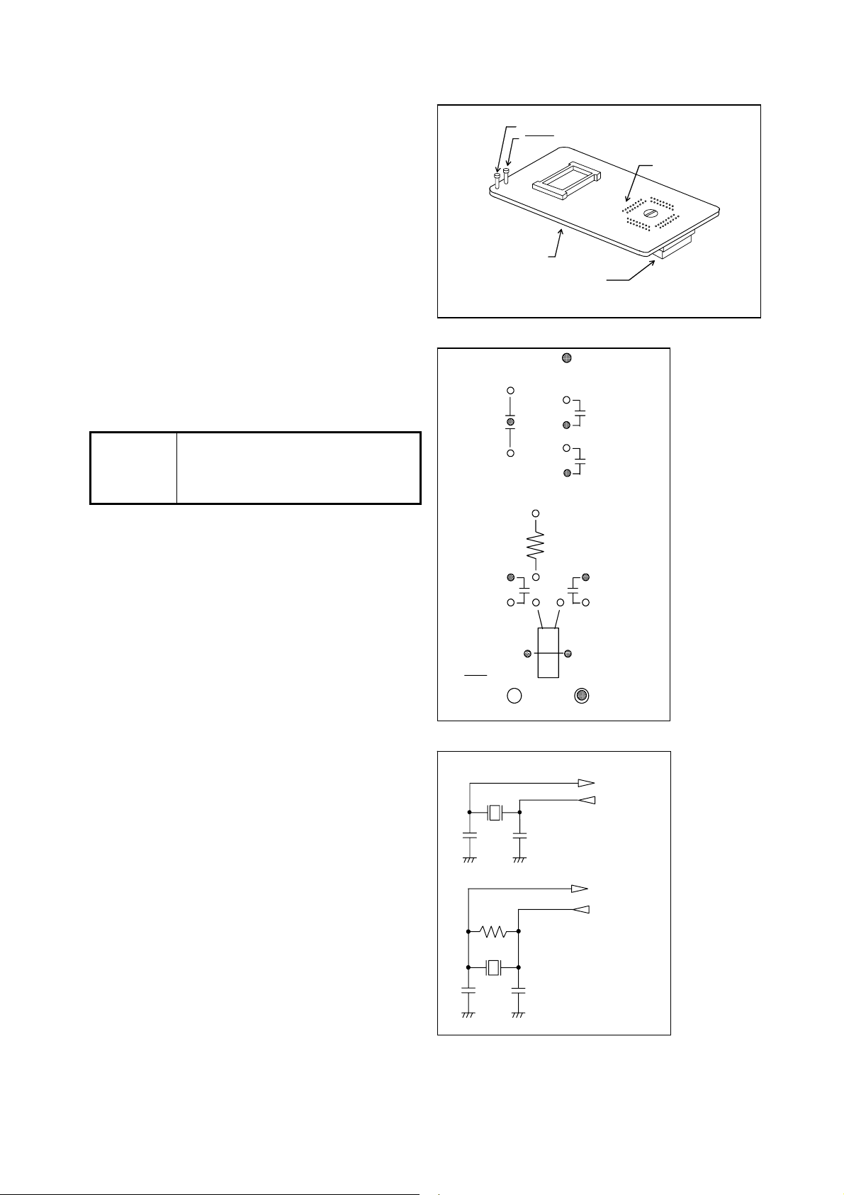
M38C29T-64LCA board
100-pin LCC socket
GND test pin
RESET test pin
64-pin header : 64D0 (J2)
Figure 1 External view of the M38C29T-64LCA
RST test pin
X1
C4
: GND
C2
C1
R1
C3
X2
GND test pin
Figure 2 Parts layout of oscillator circuits
C2
X
IN
J1- 45, J2-12
X
OUT
J1- 46, J2-13
X1
C1
X
C3
R1
X2
C4
CIN
X
COUT
J1- 43, J2-10
J1- 42, J2- 9
Figure 3 Connection diagrams of the oscillator circuits
(2/4)
Page 3

4.2 Connecting to User System
Connect the M38C29T-64LCA to the user system as follows.
(1) Set the head of the screw for releasing the LCC socket at
Polarizing pin
"LOCK" on the board as shown in Figure 4. Turn the
screw until it clicks.
(2) Mount the 64-pin header of the M38C29T-64LCA to the
64-pin LCC socket aligning the polarizing pin.
(3) The 64-pin header and 64-pin LCC socket are rated at 50
mate/demate cycles.
Figure 4 Connecting to the user system
4.3 Removing from User System
Remove the M38C29T-64LCA from the user system as
Polarizing pin
follows.
(1) Turn the screw for releasing the LCC socket clockwise as
shown in Figure 5.
(2) The M38C29T-64LCA is pushed out from the 64-pin LCC
socket.
(3) After the socket is removed, turn the screw until it clicks.
Figure 5 Removing from the user system
5. External Dimensions of the M38C29T-64LCA
E
No. 1 pin
H
F
G
J1
J2
GND
RST
Figure 6 External dimensions of the M38C29T-64LCA
A
B
M38C29T- 64LCA
64
1
LOCK
LOCK
LOCK
64
M38C29T- 64LCA
RELEASE
1
C
D
64
1
64-pin LCC socket
64
1
64-pin LCC socket
Symbol Dimension [mm]
A 17.2
B 8.7
C 21.3
D 24.2
E 70.0
F 48.7
G 21.3
H 26.7
(3/4)
Page 4

6. Precautions
CAUTION
Cautions to Be Taken for This Product:
z Before mounting the M38C29T-64LCA, be sure to check the pin positions.
IMPORTANT
Notes on This Product:
z We cannot accept any request for repair.
z For inquiries about the product or the contents of this manual, contact your local distributor.
Renesas Tools Homepage http://www.renesas.com/tools
7. Correspondence of the Connectors
Table 2 Correspondence of connectors J1 and J2
J1 connector
Pin No.
1 - 26 - 51 - 76 2 - 27 - 52 - 77 3 - 28 - 53 - 78 4 - 29 - 54 - 79 5 - 30 - 55 - 80 6 - 31 - 56 - 81 7 - 32 - 57 - 82 8 49 33 1 58 17 83 33
9 50 34 2 59 18 84 34
10 51 35 3 60 19 85 35
11 52 36 4 61 20 86 36
12 53 37 5 62 21 87 37
13 54 38 6 63 22 88 38
14 55 39 7 64 23 89 39
15 56 40 - 65 24 90 40
16 57 41 8 66 25 91 41
17 58 42 9 67 26 92 42
18 59 43 10 68 27 93 43
19 60 44 11 69 28 94 44
20 61 45 12 70 29 95 45
21 62 46 13 71 30 96 46
22 63 47 14 72 31 97 47
23 64 48 15 73 32 98 48
24 - 49 16 74 - 99 25 - 50 - 75 - 100 -
("-": No connection)
J2 connector
Pin No.
J1 connector
Pin No.
J2 connector
Pin No.
J1 connector
Pin No.
J2 connector
Pin No.
J1 connector
Pin No.
J2 connector
Pin No.
(4/4)
 Loading...