

Page 1

To our customers,
Old Company Name in Catalogs and Other Documents
On April 1st, 2010, NEC Electronics Corporation merged with Renesas Technology
Corporation, and Renesas Electronics Corporation took over all the business of both
companies. Therefore, although the old company name remains in this document, it is a valid
Renesas Electronics document. We appreciate your understanding.
Renesas Electronics website: http://www.renesas.com
April 1
Renesas Electronics Corporation
Issued by: Renesas Electronics Corporation (http://www.renesas.com)
st
, 2010
Send any inquiries to http://www.renesas.com/inquiry
.
Page 2

Notice
1. All information included in this document is current as of the date this document is issued. Such information, however, is
subject to change without any prior notice. Before purchasing or using any Renesas Electronics products listed herein, please
confirm the latest product information with a Renesas Electronics sales office. Also, please pay regular and careful attention to
additional and different information to be disclosed by Renesas Electronics such as that disclosed through our website.
2. Renesas Electronics does not assume any liability for infringement of patents, copyrights, or other intellectual property rights
of third parties by or arising from the use of Renesas Electronics products or technical information described in this document.
No license, express, implied or otherwise, is granted hereby under any patents, copyrights or other intellectual property rights
of Renesas Electronics or others.
3. You should not alter, modify, copy, or otherwise misappropriate any Renesas Electronics product, whether in whole or in part.
4. Descriptions of circuits, software and other related information in this document are provided only to illustrate the operation of
semiconductor products and application examples. You are fully responsible for the incorporation of these circuits, software,
and information in the design of your equipment. Renesas Electronics assumes no responsibility for any losses incurred by
you or third parties arising from the use of these circuits, software, or information.
5. When exporting the products or technology described in this document, you should comply with the applicable export control
laws and regulations and follow the procedures required by such laws and regulations. You should not use Renesas
Electronics products or the technology described in this document for any purpose relating to military applications or use by
the military, including but not limited to the development of weapons of mass destruction. Renesas Electronics products and
technology may not be used for or incorporated into any products or systems whose manufacture, use, or sale is prohibited
under any applicable domestic or foreign laws or regulations.
6. Renesas Electronics has used reasonable care in preparing the information included in this document, but Renesas Electronics
does not warrant that such informatio n is error free. Renesas Electronics assumes no liability whatsoever for any damages
incurred by you resulting from errors in or omissions from the information included herein.
7. Renesas Electronics products are classified according to the following three quality grades: “Standard”, “High Quality”, and
“Specific”. The recommended applications for each Renesas Electronics product depends on the product’s quality grade, as
indicated below. You must check the quality grade of each Renesas Electronics product before using it in a particular
application. You may not use any Renesas Electronics product for any application categorized as “Specific” without the prior
written consent of Renesas Electronics. Further, you may not use any Renesas Electronics product for any application for
which it is not intended without the prior written consent of Renesas Electronics. Renesas Electronics shall not be in any way
liable for any damages or losses incurred by you or third parties arising from the use of any Renesas Electronics product for an
application categorized as “Specific” or for which the product is not intended where you have failed to obtain the prior written
consent of Renesas Electronics. The quality grade of each Renesas Electronics product is “Standard” unless otherwise
expressly specified in a Ren esas E lectronics data sheets or dat a books, etc.
“Standard”: Computers; office equipment; communications equipment; test and measurement equipment; audio and visual
equipment; home electron ic appliances; machine tools; personal electronic equipment; and industrial robots.
“High Quality”: Transportation equipment (automobiles, trains, ships, etc.); traffic control systems; anti-disaster systems; anti-
crime systems; safety equipment; and medical equipment not specifically designed for life support.
“Specific”: Aircraft; aerospace equipment; submersible repeaters; nuclear reactor control systems; medical equipment or
systems for life support (e.g. artificial life support devices or systems), surgical implantations, or healthcare
intervention (e.g. excision, etc.), and any other appl i cations or purposes that pose a d irect threat to human life.
8. You should use the Renesas Electronics products described in this document within the range specified by Renesas Electronics,
especially with respect to the maximum rating, operating supply voltage range, movement power voltage range, heat radiation
characteristics, installation and other product characteristics. Renesas Electronics shall have no liability for malfunctions or
damages arising out of the use of Renesas Electronics products beyond such specified ranges.
9. Although Renesas Electronics endeavors to improve the quality and reliability of its products, semiconductor products have
specific characteristics such as t he occu rrence o f failure at a certai n rate an d malfunct io ns under cert ain u se con dition s. Further,
Renesas Electronics prod ucts are not subject to radiation resistance design. Please be sure to implement safety measures to
guard them against the possibility of physical injury, and injury or damage caused by fire in the event of the failure of a
Renesas Electronics product, such as safety design for hardware and software including but not limited to redundancy, fire
control and malfunction prevention, appropriate treatment for aging degradation or any other appropriate measures. Because
the evaluation of microcomputer software alone is very difficult, please evaluate the safety of the final products or system
manufactured by you.
10. Please contact a Renesas Electronics sales office for details as to environmental matters such as the environmental
compatibility of each Renesas Electronics product. Please use Renesas Electronics products in compliance with all applicable
laws and regulations that regulate the inclusion or use of controlled substances, including without limitation, the EU RoHS
Directive. Renesas Electronics assumes no liability for damages or losses occurring as a result of your noncompliance with
applicable laws and regulations.
11. This document may not be reproduced or duplicated, in any form, in whole or in part, without prior written consent of Renesas
Electronics.
12. Please contact a Renesas Electronics sales office if you have any questions regarding the information contained in this
document or Renesas Electronics products, or if you have any other inquiries.
(Note 1) “Renesas Electronics” as used in this document means Renesas Electronics Corporation an d also includes its majority-
owned subsidiaries.
(Note 2) “Renesas Electronics product(s)” means any product developed or manufactured by or for Renesas Electronics.
Page 3

User’s Manual
32
M32R-FPU
Software Manual
RENESAS 32-BIT RISC SINGLE-CHIP
MICROCOMPUTER
All information contained in these materials, including products and product specifications,
represents information on the product at the time of publication and is subject to change by
Renesas Electronics Corp. without notice. Please review the latest information published by
Renesas Electronics Corp. through various means, including the Renesas Electronics Corp.
website (http://www.renesas.com).
Rev.1.01 2003.10
Page 4

Keep safety first in your circuit designs!
•
Renesas Technology Corporation puts the maximum ef fort into making semiconductor products better and more reliable, but there is always the possibility that trouble may occur with
them. Trouble with semiconductors may lead to personal injury, fire or property damage.
Remember to give due consideration to safety when making your circuit designs, with appropriate measures such as (i) placement of substitutive, auxiliary circuits, (ii) use of nonflammable material or (iii) prevention against any malfunction or mishap.
Notes regarding these materials
• These materials are intended as a reference to assist our customers in the selection of the
Renesas Technology Corporation product best suited to the customer's application; they do
not convey any license under any intellectual property rights, or any other rights, belonging
to Renesas Technology Corporation or a third party.
• Renesas Technology Corporation assumes no responsibility for any damage, or infringement of any third-party's rights, originating in the use of any product data, diagrams, charts,
programs, algorithms, or circuit application examples contained in these materials.
• All information contained in these materials, including product data, diagrams, charts, programs and algorithms represents information on products at the time of publication of these
materials, and are subject to change by Renesas Technology Corporation without notice
due to product improvements or other reasons. It is therefore recommended that customers contact Renesas Technology Corporation or an authorized Renesas Technology Corporation product distributor for the latest product information before purchasing a product
listed herein.
The information described here may contain technical inaccuracies or typographical errors.
Renesas Technology Corporation assumes no responsibility for any damage, liability, or
other loss rising from these inaccuracies or errors.
Please also pay attention to information published by Renesas Technology Corporation by
various means, including the Renesas Technology Corporation Semiconductor home page
(http://www.renesas.com).
• When using any or all of the information contained in these materials, including product
data, diagrams, charts, programs, and algorithms, please be sure to evaluate all information as a total system before making a final decision on the applicability of the information
and products. Renesas Technology Corporation assumes no responsibility for any damage, liability or other loss resulting from the information contained herein.
• Renesas Technology Corporation semiconductors are not designed or manufactured for
use in a device or system that is used under circumstances in which human life is potentially at stake. Please contact Renesas Technology Corporation or an authorized Renesas
Technology Corporation product distributor when considering the use of a product contained herein for any specific purposes, such as apparatus or systems for transportation,
vehicular, medical, aerospace, nuclear, or undersea repeater use.
• The prior written approval of Renesas Technology Corporation is necessary to reprint or
reproduce in whole or in part these materials.
• If these products or technologies are subject to the Japanese export control restrictions,
they must be exported under a license from the Japanese government and cannot be imported into a country other than the approved destination.
Any diversion or reexport contrary to the export control laws and regulations of Japan and/
or the country of destination is prohibited.
• Please contact Renesas Technology Corporation for further details on these materials or
the products contained therein.
Page 5

REVISION HISTORY
M32R-FPU Software Manual
Rev. Date Description
Page Summary
1.00 Jan 08, 2003 First edition issued –
1.01 Oct 31, 2003 Hexadecimal Instruction Code Table corrected (BTST instruction)APPENDICES-3
APPENDICES-8
Appendix Figure 3.1.1 corrected
Incorrect) *The E1 stage of the FDIV instruction requires 13 cycles.
Correct) *The E1 stage of the FDIV instruction requires 14 cycles.
APPENDICES-10
Appendix Figure 3.2.1 corrected
Incorrect) LD1 Correct) LDI
APPENDICES-13
Appendix Figure 3.2.4 corrected
Incorrect) ADD R1,R6,R7 Correct) FMADD R1,R6,R7
Page 6

Table of contents
CHAPTER 1 CPU PROGRAMMING MODEL
1.1 CPU register .......................................................................................................... 1-2
1.2 General-purpose registers ...................................................................................... 1-2
1.3 Control registers ..................................................................................................... 1-3
1.3.1 Processor status word register: PSW (CR0) ...................................... 1-4
1.3.2 Condition bit register: CBR (CR1) ......................................................1-5
1.3.3 Interrupt stack pointer: SPI (CR2)
User stack pointer: SPU (CR3) ..........................................................1-5
1.3.4 Backup PC: BPC (CR6) .....................................................................1-5
1.3.5 Floating-Point Status Register: FPSR (CR7) .....................................1-6
1.3.6 Floating-Point Exceptions (FPE) ........................................................1-8
1.4 Accumulator............................................................................................................ 1-11
1.5 Program counter ..................................................................................................... 1-11
1.6 Data format ............................................................................................................. 1-12
1.6.1 Data type ............................................................................................1-12
1.6.2 Data format......................................................................................... 1-13
1.7 Addressing mode.................................................................................................... 1-15
CHAPTER 2 INSTRUCTION SET
2.1 Instruction set overview ......................................................................................... 2-2
2.1.1 Load/store instructions .......................................................................2-2
2.1.2 Transfer instructions...........................................................................2-4
2.1.3 Operation instructions ........................................................................2-4
2.1.4 Branch instructions.............................................................................2-6
2.1.5 EIT-related instructions ......................................................................2-8
2.1.6 DSP function instructions ...................................................................2-8
2.1.7 Floating-point Instructions ..................................................................2-11
2.1.8 Bit Operation Instructions ................................................................... 2-11
2.2 Instruction format ................................................................................................... 2-12
(1)
M32R-FPU Software Manual (Rev.1.01)
Page 7

CHAPTER 3 INSTRUCTIONS
3.1 Conventions for instruction description................................................................... 3-2
3.2 Instruction description............................................................................................. 3-5
APPENDIX
Appendix 1 Hexadecimal Instraction Code..................................................................
Appendix 2 Instruction List...........................................................................................
Appendix 3 Pipeline Processing ..................................................................................
Appendix 3.1 Instructions and Pipeline Processing ....................................
Appendix 3.2 Pipeline Basic Operation .......................................................
Appendix 4 Instruction Execution Time .......................................................................
Appendix 5 IEEE754 Specification Overview ..............................................................
Appendix 5.1 Floating Point Formats ..........................................................
Appendix 5.2 Rounding ...............................................................................
Appendix 5.3 Exceptions.............................................................................
Appendix 6 M32R-FPU Specification Supplemental Explanation ......................................
Appendix 6.1 Operation Comparision: Using 1 instruction (FMADD or FMSBU)
vs. two instructions (FMUL and FADD) .................................
Appendix 6.1.1 Rounding Mode ............................................................
Appendix 6.1.2 Exception occurring in Step 1 .......................................
Appendix 6.2 Rules concerning Generation of QNaN in M32R-FPU ...........
Appendix 7 Precautions...............................................................................................
Appendix 7.1 Precautions to be taken when aligning data...........................
Appendix
Appendix
Appendix
Appendix
Appendix
Appendix
Appendix
Appendix
Appendix
Appendix
Appendix
-2
Appendix
-4
Appendix
-8
-8
-10
Appendix
-17
Appendix
-18
-18
-20
-20
Appendix
-23
-23
-23
-23
-28
Appendix
-29
-29
INDEX
(2)
M32R-FPU Software Manual (Rev.1.01)
Page 8

This page left blank intentionally.
M32R-FPU Software Manual (Rev.1.01)
Page 9

CHAPTER 1
CPU PROGRAMMIING MODEL
1.1 CPU Register
1.2 General-purpose Registers
1.3 Control Registers
1.4 Accumulator
1.5 Program Counter
1.6 Data Format
1.7 Addressing Mode
Page 10

CPU PROGRAMMING MODEL
1
1.1 CPU Register
The M32R family CPU, with a built-in FPU (herein referred to as M32R-FPU) has 16
general-purpose registers, 6 control registers, an accumulator and a program
counter. The accumulator is of 56-bit configuration, and all other registers are a 32bit configuration.
1.2 General-purpose Registers
The 16 general-purpose registers (R0 – R15) are of 32-bit width and are used to
retain data and base addresses, as well as for integer calculations, floating-point
operations, etc. R14 is used as the link register and R15 as the stack pointer. The link
register is used to store the return address when executing a subroutine call
instruction. The Interrupt Stack Pointer (SPI) and the User Stack Pointer (SPU) are
alternately represented by R15 depending on the value of the Stack Mode (SM) bit in
the Processor Status Word Register (PSW).
At reset release, the value of the general-purpose registers is undefined.
1.1 CPU Register
b0
Note 1: The stack pointer functions as either the SPI or the SPU depending on the value of the SM bit in the PSW.
b31
R0
R1
R2
R3
R4
R5
R6
R7
b0
b31
R8
R9
R10
R11
R12
R13
R14 (Link register)
R15 (Stack pointer)
Figure 1.2.1 General-purpose Registers
(Note 1)
1-2
M32R-FPU Software Manual (Rev.1.01)
Page 11

CPU PROGRAMMING MODEL
1
1.3 Control Registers
1.3 Control Registers
There are 6 control registers which are the Processor Status Word Register (PSW),
the Condition Bit Register (CBR), the Interrupt Stack Pointer (SPI), the User Stack
Pointer (SPU), the Backup PC (BPC) and the Floating-point Status Register (FPSR).
The dedicated MVTC and MVFC instructions are used for writing and reading these
control registers.
In addition, the SM bit, IE bit and C bit of the PSW can also be set by the SETPSW
instruction or the CLRPSW instruction.
CRn
Notes: • CRn (n = 0 - 3, 6 and 7) denotes the control register number.
• The dedicated MVTC and MVFC instructions are used for writing and reading these control registers.
• The SM bit, IE bit and C bit of the PSW can also be set by the SETPSW instruction or the CLRPSW
instruction.
Figure 1.3.1 Control Registers
CR0
CR1
CR2
CR3
CR6
CR7
b0
PSW
CBR
SPI
SPU
BPC
FPSR
b31
Processor Status Register
Condition Bit Register
Interrupt Stack Pointer
User Stack Pointer
Backup PC
Floating-point Status Register
1-3 M32R-FPU Software Manual (Rev.1.01)
Page 12

1
1.3.1 Processor Status Word Register: PSW (CR0)
7654321 8 9 10 11 12 13 14 b15b0
CPU PROGRAMMING MODEL
1.3 Control Registers
0000 000 0000000
BIEBSM
?? 00000?00000000
b Bit Name Function R W
0-15 No function assigned. Fix to "0". 0 0
16 BSM Saves value of SM bit when EIT occurs R W
Backup SM Bit
17 BIE Saves value of IE bit when EIT occurs R W
Backup IE Bit
18-22 No function assigned. Fix to "0". 0 0
23 BC Saves value of C bit when EIT occurs R W
Backup C Bit
24 SM 0: Uses R15 as the interrupt stack pointer R W
Stack Mode Bit 1: Uses R15 as the user stack pointer
25 IE 0: Does not accept interrupt R W
Interrupt Enable Bit 1: Accepts interrupt
26-30 No function assigned. Fix to "0". 0 0
31 C Indicates carry, borrow and overflow resulting R W
Condition Bit from operations (instruction dependent)
00
BPSW field
23 24 25 26 27 28 29 30 b3117 18 19 20 21 22b16
BC SM IE C
PSW field
< At reset release: "B'0000 0000 0000 0000 ??00 000? 0000 0000 >
The Processor Status Word Register (PSW) indicates the M32R-FPU status. It
consists of the current PSW field which is regularly used, and the BPSW field where
a copy of the PSW field is saved when EIT occurs.
The PSW field consists of the Stack Mode (SM) bit, the Interrupt Enable (IE) bit and
the Condition (C) bit.
The BPSW field consists of the Backup Stack Mode (BSM) bit, the Backup Interrupt
Enable (BIE) bit and the Backup Condition (BC) bit.
At reset release, BSM, BIE and BC are undefined. All other bits are "0".
1-4
M32R-FPU Software Manual (Rev.1.01)
Page 13

1
1.3.2 Condition Bit Register: CBR (CR1)
The Condition Bit Register (CBR) is derived from the PSW register by extracting its
Condition (C) bit. The value written to the PSW register's C bit is reflected in this
register. The register can only be read. (Writing to the register with the MVTC
instruction is ignored.)
At reset release, the value of CBR is "H'0000 0000".
b0
0000000000000000000000000000000
CBR
1.3.3 Interrupt Stack Pointer: SPI (CR2) User Stack Pointer: SPU (CR3)
The Interrupt Stack Pointer (SPI) and the User Stack Pointer (SPU) retain the
address of the current stack pointer. These registers can be accessed as the
general-purpose register R15. R15 switches between representing the SPI and
SPU depending on the value of the Stack Mode (SM) bit in the PSW.
At reset release, the value of the SPI and SPU are undefined.
CPU PROGRAMMING MODEL
1.3 Control Registers
b31
C
b0
SPI
b0
SPU
SPI
SPU
1.3.4 Backup PC: BPC (CR6)
The Backup PC (BPC) is used to save the value of the Program Counter (PC) when
an EIT occurs. Bit 31 is fixed to "0".
When an EIT occurs, the register sets either the PC value when the EIT occurred or
the PC value for the next instruction depending on the type of EIT. The BPC value
is loaded to the PC when the RTE instruction is executed. However, the values of
the lower 2 bits of the PC are always "00" when returned (PC always returns to the
word-aligned address).
At reset release, the value of the BPC is undefined.
b0
BPC
BPC
b31
b31
b31
0
1-5 M32R-FPU Software Manual (Rev.1.01)
Page 14

CPU PROGRAMMING MODEL
1
1.3.5 Floating-point Status Register: FPSR (CR7)
234567891011121314b151b0
FS FX FU FZ
0000 00 0 0000000
18 19 20 21 22 23 24 25 26 27 28 29 30 b3117b16
EZ EO
EUEX
00 00000100000000
b Bit Name Function R W
0 FS Reflects the logical sum of FU, FZ, FO and FV. R –
Floating-point Exception
Summary Bit
1 FX Set to "1" when an inexact exception occurs R W
Inexact Exception Flag (if EIT processing is unexecuted (Note 1)).
2 FU Set to "1" when an underflow exception occurs R W
Underflow Exception Flag (if EIT processing is unexecuted (Note 1)).
3 FZ Set to "1" when a zero divide exception occurs R W
Zero Divide Exception Flag (if EIT processing is unexecuted (Note 1)).
4 FO Set to "1" when an overflow exception occurs R W
Overflow Exception Flag (if EIT processing is unexecuted (Note 1)).
5 FV Set to "1" when an invalid operation exception R W
Invalid Operation Exception occurs (if EIT processing is unexecuted (Note 1)).
Flag Once set, the flag retains the value "1" until
6–16 No function assigned. Fix to "0". 0 0
17 EX 0: Mask EIT processing to be executed when an R W
Inexact Exception Enable inexact exception occurs
Bit 1: Execute EIT processing when an inexact
18 EU 0: Mask EIT processing to be executed when an R W
Underflow Exception Enable underflow exception occurs
Bit 1: Execute EIT processing when an underflow
19 EZ 0: Mask EIT processing to be executed when a R W
Zero Divide Exception zero divide exception occurs
Enable Bit 1: Execute EIT processing when a zero divide
20 EO 0: Mask EIT processing to be executed when an R W
Overflow Exception overflow exception occurs
Enable Bit 1: Execute EIT processing when an overflow
0FO0
FV
EV
DN CE CX CU CZ CO CV RM
Once set, the flag retains the value "1" until
it is cleared to "0" in software.
Once set, the flag retains the value "1" until
it is cleared to "0" in software.
Once set, the flag retains the value "1" until
it is cleared to "0" in software.
Once set, the flag retains the value "1" until
it is cleared to "0" in software.
it is cleared to "0" in software.
exception occurs
exception occurs
exception occurs
exception occurs
<At reset release: H0000 0100>
1.3 Control Registers
1-6
M32R-FPU Software Manual (Rev.1.01)
Page 15

CPU PROGRAMMING MODEL
1
21 EV 0: Mask EIT processing to be executed when an R W
Invalid Operation Exception invalid operation exception occurs
Enable Bit 1: Execute EIT processing when an invalid
operation exception occurs
22 No function assigned. Fix to "0". 0 0
23 DN 0: Handle the denormalized number as a R W
Denormalized Number Zero denormalized number
Flash Bit (Note 2) 1: Handle the denormalized number as zero
24 CE 0: No unimplemented operation exception occurred . R(Note 3)
Unimplemented Operation 1: An unimplemented operation exception occurred.
Exception Cause Bit When the bit is set to "1", the execution of an
FPU operation instruction will clear it to "0".
25 CX 0: No inexact exception occurred. R (Note 3)
Inexact Exception Cause 1: An inexact exception occurred.
Bit When the bit is set to "1", the execution of an
FPU operation instruction will clear it to "0".
26 CU 0: No underflow exception occurred. R (Note 3)
Underflow Exception Cause 1: An underflow exception occurred.
Bit When the bit is set to "1", the execution of an
FPU operation instruction will clear it to "0".
27 CZ 0: No zero divide exception occurred. R (Note 3)
Zero Divide Exception 1: A zero divide exception occurred.
Cause Bit When the bit is set to "1", the execution of an
FPU operation instruction will clear it to "0".
28 CO 0: No overflow exception occurred. R(Note 3)
Overflow Exception 1: An overflow exception occurred.
Cause Bit When the bit is set to "1", the execution of an
FPU operation instruction will clear it to "0".
29 CV 0: No invalid operation exception occurred. R (Note 3)
Invalid Operation Exception 1: An invalid operation exception occurred.
Cause Bit When the bit is set to "1", the execution of an
FPU operation instruction will clear it to "0".
30, 31 RM 00: Round to Nearest R W
Rounding Mode Selection Bit 01: Round toward Zero
10: Round toward +Infinity
11: Round toward -Infinity
Note 1: ‘If EIT processing is unexecuted’ means whenever one of the exceptions occurs, enable bits
17 to 21 are set to "0" which masks the EIT processing so that it cannot be executed. If two
exceptions occur at the same time and their corresponding exception enable bits are
set differently (one enabled, and the other masked), EIT processing is executed. In this
case, these two flags do not change state regardless of the enable bit settings.
Note 2: If a denormalized number is given to the operand when DN = "0", an unimplemented
exception occurs.
Note 3: This bit is cleared by writing "0". Writing "1" has no effect (the bit retains the value it had
before the write).
1.3 Control Registers
1-7 M32R-FPU Software Manual (Rev.1.01)
Page 16

CPU PROGRAMMING MODEL
1
1.3.6 Floating-point Exceptions (FPE)
Floating-point Exception (FPE) occurs when Unimplemented Exception (UIPL) or
one of the five exceptions specified in the IEEE754 standard (OVF/UDF/IXCT/
DIV0/IVLD) is detected. Each exception processing is outlined below.
(1) Overflow Exception (OVF)
The exception occurs when the absolute value of the operation result exceeds the
largest describable precision in the floating-point format. The following table shows
the operation results when an OVF occurs.
Operation Result (Content of the Destination Register)
Rounding Mode Sign of the Result When the OVF EIT processing When the OVF EIT processing
is masked (Note 1) is executed (Note 2)
–infinity + +MAX
––infinity
+infinity + +infinity
––MAX No change
0 + +MAX
––MAX
Nearest + +infinity
––infinity
Note 1: When the Overflow Exception Enable (EO) bit (FPSR register bit 20) = "0"
Note 2: When the Overflow Exception Enable (EO) bit (FPSR register bit 20) = "1"
Note: • If an OVF occurs while EIT processing for OVF is masked, an IXCT occurs at the same time.
• +MAX = H'7F7F FFFF, –MAX = H'FF7F FFFF
1.3 Control Registers
(2) Underflow Exception (UDF)
The exception occurs when the absolute value of the operation result is less than
the largest describable precision in the floating-point format. The following table
shows the operation results when a UDF occurs.
Operation Result (Content of the Destination Register)
When UDF EIT processing is masked (Note 1) When UDF EIT processing is executed (Note 2)
DN = 0: An unimplemented exception occurs No change
DN = 1: 0 is returned
Note 1: When the Underflow Exception Enable (EU) bit (FPSR register bit 18) = "0"
Note 2: When the Underflow Exception Enable (EU) bit (FPSR register bit 18) = "1"
1-8
M32R-FPU Software Manual (Rev.1.01)
Page 17

CPU PROGRAMMING MODEL
1
(3) Inexact Exception (IXCT)
The exception occurs when the operation result differs from a result led out with an
infinite range of precision. The following table shows the operation results and the
respective conditions in which each IXCT occurs.
Operation Result (Content of the Destination Register)
Occurrence Condition When the IXCT EIT processing is When the IXCT EIT processing is
masked (Note 1) executed (Note 2)
Overflow occurs in OVF Reference OVF operation results No change
masked condition
Rounding occurs Rounded value No change
Note 1: When the Inexact Exception Enable (EX) bit (FPSR register bit 17) = "0"
Note 2: When the Inexact Exception Enable (EX) bit (FPSR register bit 17) = "1"
(4) Zero Division Exception (DIV0)
The exception occurs when a finite nonzero value is divided by zero. The following
table shows the operation results when a DIV0 occurs.
1.3 Control Registers
Operation Result (Content of the Destination Register)
Dividend When the DIV0 EIT processing is When the DIV0 EIT processing is
masked (Note 1) executed (Note 2)
Nonzero finite value ±infinity (Sign is derived by exclusive- No change
ORing the signs of divisor and dividend)
Note 1: When the Zero Division Exception Enable (EZ) bit (FPSR register bit 19) = "0"
Note 2: When the Zero Division Exception Enable (EZ) bit (FPSR register bit 19) = "1"
Please note that the DIV0 EIT processing does not occur in the following conditions.
Dividend Behavior
0 An invalid operation exception occurs
infinity No exception occur (with the result "infinity")
1-9 M32R-FPU Software Manual (Rev.1.01)
Page 18

CPU PROGRAMMING MODEL
1
(5) Invalid Operation Exception (IVLD)
The exception occurs when an invalid operation is executed. The following table shows
the operation results and the respective conditions in which each IVLD occurs.
Occurrence Condition Operation Result (Content of the Destination Register)
When the IVLD EIT processing When the IVLD EIT
is masked (Note 1) processing is executed
Operation for SNaN operand
+infinity -(+infinity), -infinity -(-infinity) QNaN
0 ✕ infinity
0 ÷ 0, infinity ÷ infinity
When FTOI Return value when
instruction pre-conversion signed bit is:
When an integer conversion was executed "0" = H’7FFF FFFF No change
overflowed "1" = H’8000 0000
When NaN or Infinity was When FTOS Return value when
converted into an integer instruction pre-conversion signed bit is:
was executed "0" = H’0000 7FFF
"1" = H’FFF 8000
When < or > comparison was Comparison results
performed on NaN (comparison invalid)
Note 1: When the Invalid Operation Exception Enable (EV) bit (FPSR register bit 21) = "0"
Note 2: When the Invalid Operation Exception Enable (EV) bit (FPSR register bit 21) = "1"
Notes: • NaN (Not a Number)
SNaN (Signaling NaN): a NaN in which the MSB of the decimal fraction is “0”. When
SNaN is used as the source operand in an operation, an IVLD occurs. SNaNs are useful
in identifying program bugs when used as the initial value in a variable. However,
SNaNs cannot be generated by hardware.
QNaN (Quiet NaN): a NaN in which the MSB of the decimal fraction is "1". Even when
QNaN is used as the source operand in an operation, an IVLD will not occur (excluding
comparison and format conversion). Because a result can be checked by the arithmetic
operations, QNaN allows the user to debug without executing an EIT processing.
QNaNs are created by hardware.
1.3 Control Registers
(Note 2)
(6) Unimplemented Exception (UIPL)
The exception occurs when the Denormalized Number Zero Flash (DN) bit (FPSR
register bit 23) = "0" and a denormalized number is given as an operation operand
(Note 1).
Because the UIPL has no enable bits available, it cannot be masked when they
occur. The destination register remains unchanged.
Note: • A UDF occurs when the intermediate result of an operation is a denormalized
number, in which case if the DN bit (FPSR register bit 23) = "0", an UIPL occurs.
1-10
M32R-FPU Software Manual (Rev.1.01)
Page 19

CPU PROGRAMMING MODEL
1
1.4 Accumulator
The Accumulator (ACC) is a 56-bit register used for DSP function instructions.
The accumulator is handled as a 64-bit register when accessed for read or write.
When reading data from the accumulator, the value of bit 8 is sign-extended. When
writing data to the accumulator, bits 0 to 7 are ignored. The accumulator is also used
for the multiply instruction "MUL", in which case the accumulator value is destroyed
by instruction execution.
Use the MVTACHI and MVTACLO instructions for writing to the accumulator. The
MVTACHI and MVTACLO instructions write data to the high-order 32 bits (bits 0-31)
and the low-order 32 bits (bits 32-63), respectively.
Use the MVFACHI, MVFACLO, and MVFACMI instructions for reading data from the
accumulator. The MVFACHI, MVFACLO and MVFACMI instructions read data from
the high-order 32 bits (bits 0-31), the low-order 32 bits (bits 32-63) and the middle 32
bits (bits 16-47), respectively.
At reset release, the value of accumulator is undefined.
1.4 Accumulator
(Note 1)
ACC
read/write range with
MVTACHI or MVFACHI instruction
Note 1: When read, bits 0 to 7 always show the sign-extended value of bit 8. Writing to this bit field is
ignored.
read range with MVFACMI instruction
32 48 b63311615b0 4778
read/write range with
MVTACLO or MVFACLO instruction
1.5 Program Counter
The Program Counter (PC) is a 32-bit counter that retains the address of the
instruction being executed. Since the M32R CPU instruction starts with evennumbered addresses, the LSB (bit 31) is always "0".
At reset release, the value of the PC is "H’0000 0000."
b0
PC
PC
b31
0
1-11 M32R-FPU Software Manual (Rev.1.01)
Page 20

1
1.6 Data Format
1.6.1 Data Type
The data types that can be handled by the M32R-FPU instruction set are signed or
unsigned 8, 16, and 32-bit integers and single-precision floating-point numbers.
The signed integers are represented by 2's complements.
CPU PROGRAMMING MODEL
1.6 Data Format
signed byte (8-bit) integer
unsigned byte (8-bit) integer
signed halfword (16-bit) integer
unsigned halfword (16-bit) integer
signed word (32-bit) integer
unsigned word (32-bit) integer
floating-point single precision values
Figure 1.6.1 Data Type
b0
S
b0
S
b0
b0
S
b0
b0 8 9 b31
SE F
b7
b7b0
b15
b15
S: Sign bit E: Exponent field F: Fraction field
b31
b31
1-12
M32R-FPU Software Manual (Rev.1.01)
Page 21
1
1.6.2 Data Format
(1) Data format in a register
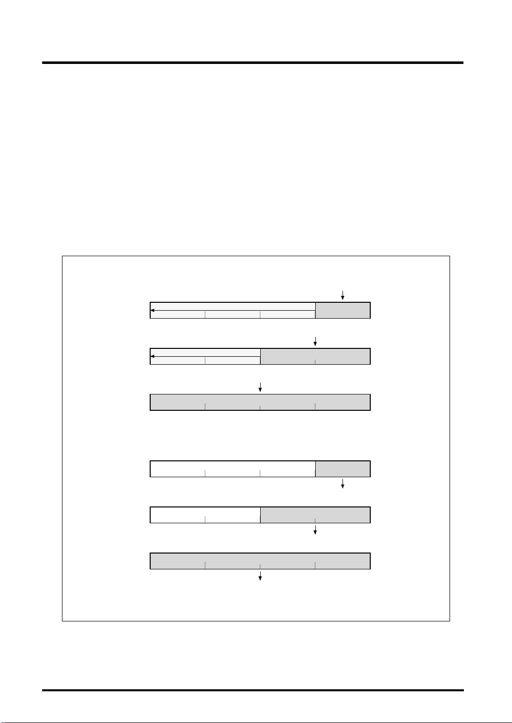
The data sizes in the M32R-FPU registers are always words (32 bits).
When loading byte (8-bit) or halfword (16-bit) data from memory into a register, the
data is sign-extended (LDB, LDH instructions) or zero-extended (LDUB, LDUH
instructions) to a word (32-bit) quantity before being loaded into the register.
When storing data from a register into a memory, the 32-bit data, the 16-bit data on
the LSB side and the 8-bit data on the LSB side of the register are stored into
memory by the ST, STH and STB instructions, respectively.
CPU PROGRAMMING MODEL
1.6 Data Format
< load >
b0 b31
Rn
sign-extention (LDH instruction) or
zero-extention (LDUH instruction)
b0 b31
Rn
b0 b31
Rn
< store >
b0 b31
Rn
b0 b31
Rn
b0 b31
Rn
sign-extention (LDB instruction) or
zero-extention (LDUB
instruction)
16
from memory (LD instruction
word
16
word
from memory (LDH, LDUH
(LDB, LDUB instruction)
halfword
)
to memory (STB instruction)
halfword
to memory (STH instruction)
from memory
24
byte
instruction)
24
byte
Figure 1.6.2 Data Format in a Register
to memory (ST
instruction)
1-13 M32R-FPU Software Manual (Rev.1.01)
Page 22
1
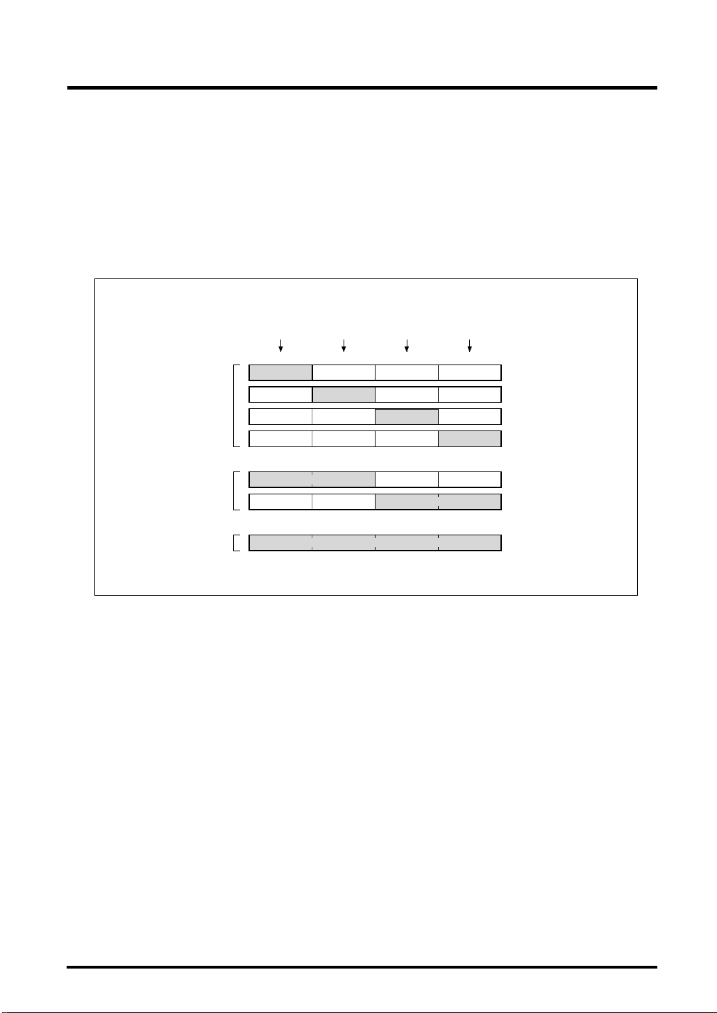
(2) Data format in memory
The data sizes in memory can be byte (8 bits), halfword (16 bits) or word (32 bits).
Although byte data can be located at any address, halfword and word data must be
located at the addresses aligned with a halfword boundary (least significant
address bit = "0") or a word boundary (two low-order address bits = "00"),
respectively. If an attempt is made to access memory data that overlaps the
halfword or word boundary, an address exception occurs.
CPU PROGRAMMING MODEL
1.6 Data Format
Address
+0 address +1 address +2 address +3 address
b0 b31
byte
byte
half
word
word
Figure 1.6.3 Data Format in Memory
7 8 15 16 23 24
byte
byte
byte
halfword
halfword
word
1-14
M32R-FPU Software Manual (Rev.1.01)
Page 23

1
1.7 Addressing Mode
M32R-FPU supports the following addressing modes.
(1) Register direct [R or CR]
The general-purpose register or the control register to be processed is
specified.
(2) Register indirect [@R]
The contents of the register specify the address of the memory. This mode
can be used by all load/store instructions.
(3) Register relative indirect [@(disp, R)]
(The contents of the register) + (16-bit immediate value which is signextended to 32 bits) specify the address of the memory.
(4) Register indirect and register update
CPU PROGRAMMING MODEL
1.7 Addressing Mode
• Adds 4 to register contents [@R+]
The contents of the register specify the memory address, then 4 is added to
the register contents.
(Can only be specified with LD instruction).
• Add 2 to register contents [@R+] [M32R-FPU extended addressing mode]
The contents of the register specify the memory address, then 2 is added to
the register contents.
(Can only be specified with STH instruction).
• Add 4 to register contents [@+R]
The contents of the register is added by 4, the register contents specify the
memory address.
(Can only be specified with ST instruction).
• Subtract 4 to register contents [@–R]
The content of the register is decreased by 4, then the register contents
specify the memory address.
(Can only be specified with ST instruction).
(5) immediate [#imm]
The 4-, 5-, 8-, 16- or 24-bit immediate value.
(6) PC relative [pcdisp]
(The contents of PC) + (8, 16, or 24-bit displacement which is sign-extended
to 32 bits and 2 bits left-shifted) specify the address of memory.
1-15 M32R-FPU Software Manual (Rev.1.01)
Page 24

1
CPU PROGRAMMING MODEL
1.7 Addressing Mode
This page left blank intentionally.
1-16
M32R-FPU Software Manual (Rev.1.01)
Page 25

CHAPTER 2
INSTRUCTION SET
2.1 Instruction set overview
2.2 Instruction format
Page 26

INSTRUCTION SET
2
2.1 Instruction set overview
2.1 Instruction set overview
The M32R-FPU has a total of 100 instructions. The M32R-FPU has a RISC architecture.
Memory is accessed by using the load/store instructions and other operations are
executed by using register-to-register operation instructions.
M32R CPU supports compound instructions such as " load & address update" and "store
& address update" which are useful for high-speed data transfer.
2.1.1 Load/store instructions
The load/store instructions carry out data transfers between a register and a memory.
LD Load
LDB Load byte
LDUB Load unsigned byte
LDH Load halfword
LDUH Load unsigned halfword
LOCK Load locked
ST Store
STB Store byte
STH Store halfword
UNLOCK Store unlocked
2-2
M32R-FPU Software Manual (Rev.1.01)
Page 27

INSTRUCTION SET
2
Three types of addressing modes can be specified for load/store instructions.
(1) Register indirect
The contents of the register specify the address. This mode can be used by all load/
store instructions.
(2) Register relative indirect
(The contents of the register) + (32-bit sign-extended 16-bit immediate value)
specifies the address. This mode can be used by all except LOCK and UNLOCK
instructions.
(3) Register indirect and register update
• Adds 4 to register contents [@R+]
The contents of the register specify the memory address, then 4 is added to the
register contents.
(Can only be specified with LD instruction).
• Add 2 to register contents [@R+] [M32R-FPU extended addressing mode]
The contents of the register specify the memory address, then 2 is added to the
register contents.
(Can only be specified with STH instruction).
2.1 Instruction set overview
• Add 4 to register contents [@+R]
The contents of the register is added by 4, the register contents specity the
memory address.
(Can only be specified with ST instruction).
• Subtract 4 to register contents [@–R]
The content of the register is decreased by 4, then the register contents specify
the memory address.
(Can only be specified with ST instruction).
When accessing halfword and word size data, it is necessary to specify the address on
the halfword boundary or the word boundary (Halfword size should be such that the loworder 2 bits of the address are "00" or "10", and word size should be such that the low
order 2 bits of the address are "00"). If an unaligned address is specified, an address
exception occurs.
When accessing byte data or halfword data with load instructions, the high-order bits are
sign-extended or zero-extended to 32 bits, and loaded to a register.
2-3 M32R-FPU Software Manual (Rev.1.01)
Page 28

INSTRUCTION SET
2
2.1.2 Transfer instructions
The transfer instructions carry out data transfers between registers or a register and an
immediate value.
LD24 Load 24-bit immediate
LDI Load immediate
MV Move register
MVFC Move from control register
MVTC Move to control register
SETH Set high-order 16-bit
2.1.3 Operation instructions
Compare, arithmetic/logic operation, multiply and divide, and shift are carried out
between registers.
2.1 Instruction set overview
• compare instructions
CMP Compare
CMPI Compare immediate
CMPU Compare unsigned
CMPUI Compare unsigned immediate
• arithmetic operation instructions
ADD Add
ADD3 Add 3-operand
ADDI Add immediate
ADDV Add with overflow checking
ADDV3 Add 3-operand with overflow checking
ADDX Add with carry
NEG Negate
SUB Subtract
SUBV Subtract with overflow checking
SUBX Subtract with borrow
2-4
M32R-FPU Software Manual (Rev.1.01)
Page 29

2
• logic operation instructions
AND AND
AND3 AND 3-operand
NOT Logical NOT
OR OR
OR3 OR 3-operand
XOR Exclusive OR
XOR3 Exclusive OR 3-operand
• multiply/divide instructions
DIV Divide
DIVU Divide unsigned
MUL Multiply
REM Remainder
REMU Remainder unsigned
• shift instructions
SLL Shift left logical
SLL3 Shift left logical 3-operand
SLLI Shift left logical immediate
SRA Shift right arithmetic
SRA3 Shift right arithmetic 3-operand
SRAI Shift right arithmetic immediate
SRL Shift right logical
SRL3 Shift right logical 3-operand
SRLI Shift right logical immediate
INSTRUCTION SET
2.1 Instruction set overview
2-5 M32R-FPU Software Manual (Rev.1.01)
Page 30

2
2.1.4 Branch instructions
The branch instructions are used to change the program flow.
BC Branch on C-bit
BEQ Branch on equal to
BEQZ Branch on equal to zero
BGEZ Branch on greater than or equal to zero
BGTZ Branch on greater than zero
BL Branch and link
BLEZ Branch on less than or equal to zero
BLTZ Branch on less than zero
BNC Branch on not C-bit
BNE Branch on not equal to
BNEZ Branch on not equal to zero
BRA Branch
JL Jump and link
JMP Jump
NOP No operation
INSTRUCTION SET
2.1 Instruction set overview
Only a word-aligned (word boundary) address can be specified for the branch address.
2-6
M32R-FPU Software Manual (Rev.1.01)
Page 31

INSTRUCTION SET
2
The addressing mode of the BRA, BL, BC and BNC instructions can specify an 8-bit or
24-bit immediate value. The addressing mode of the BEQ, BNE, BEQZ, BNEZ, BLTZ,
BGEZ, BLEZ, and BGTZ instructions can specify a 16-bit immediate value.
In the JMP and JL instructions, the register value becomes the branch address.
However, the low-order 2-bit value of the register is ignored. In other branch
instructions, (PC value of branch instruction) + (sign-extended and 2 bits left-shifted
immediate value) becomes the branch address. However, the low order 2-bit value of the
address becomes "00" when addition is carried out. For example, refer to Figure 2.1.1.
When instruction A or B is a branch instruction, branching to instruction G, the
immediate value of either instruction A or B becomes 4.
Simultaneous with execution of branching by the JL or BL instructions for subroutine
calls, the PC value of the return address is stored in R14. The low-order 2-bit value of
the address stored in R14 (PC value of the branch instruction + 4 ) is always cleared to
"0". For example, refer to Figure 2.1.1. If an instruction A or B is a JL or BL instruction,
the return address becomes that of the instruction C.
2.1 Instruction set overview
address
branch instruction
Fig. 2.1.1 Branch addresses of branch instruction
H'00
H'04
H'08
H'0C
H'10
+0 +1 +2 +3
1 word (32 bits)
instruction A instruction B
instruction C instruction D
instruction E
instruction F
instruction G instruction H
2-7 M32R-FPU Software Manual (Rev.1.01)
Page 32

INSTRUCTION SET
2
2.1.5 EIT-related instructions
The EIT-related instructions carry out the EIT events (Exception, Interrupt and Trap).
Trap initiation and return from EIT are EIT-related instructions.
TRAP Trap
RTE Return from EIT
2.1.6 DSP function instructions
The DSP function instructions carry out multiplication of 32 bits x 16 bits and 16 bits x 16
bits or multiply and add operation; there are also instructions to round off data in the
accumulator and carry out transfer of data between the accumulator and a generalpurpose register.
2.1 Instruction set overview
MACHI Multiply-accumulate high-order halfwords
MACLO Multiply-accumulate low-order halfwords
MACWHI Multiply-accumulate word and high-order halfword
MACWLO Multiply-accumulate word and low-order halfword
MULHI Multiply high-order halfwords
MULLO Multiply low-order halfwords
MULWHI Multiply word and high-order halfword
MULWLO Multiply word and low-order halfword
MVFACHI Move high-order word from accumulator
MVFACLO Move low-order word from accumulator
MVFACMI Move middle-order word from accumulator
MVTACHI Move high-order word to accumulator
MVTACLO Move low-order word to accumulator
RAC Round accumulator
RACH Round accumulator halfword
2-8
M32R-FPU Software Manual (Rev.1.01)
Page 33

2
INSTRUCTION SET
2.1 Instruction set overview
0151631
H
063
031
063
Rsrc1
0151631
H
0151631
L
x
Rsrc1
L
Rsrc1
32 bits
Rsrc2
H
x
063
L
Rsrc2
0151631
H
x
x
MULLO instructionMULHI instruction
ACC
0151631
HL
x
x
ACC
063
+
ACC
L
Rsrc2
MULWLO instructionMULWHI instruction
ACC
+
MACLO instructionMACHI instruction
Rsrc1
031
32 bits
Note: The location in the accumulator of the result and the appropriate sign extension are performed
in the execution of the DSP function instruction. Refer to Chapter 3 for details.
Rsrc2
0151631
H
x
x
063
063
L
+
+
MACWLO instructionMACWHI instruction
ACC
ACC
Fig. 2.1.2 DSP function instruction operation 1 (multiply, multiply and accumulate)
2-9 M32R-FPU Software Manual (Rev.1.01)
Page 34

2
INSTRUCTION SET
2.1 Instruction set overview
< word size round off > < halfword size round off >
063
ACC
063
ACC
RAC instruction
063063
sign 0
Note: The actual operation is processed in two steps.
Refer to Chapter 3 for details.
Fig. 2.1.3 DSP function instruction operation 2 (round off)
MVFACMI instruction
15 16 31 32
063
ACC
MVFACHI
instruction
031
Rdest
47 48
MVFACLO
instruction
RACH instruction
sign 0
MVTACHI
instruction
063
datadata
031
Rsrc
MVTACLO
instruction
31 32
ACC
Fig. 2.1.4 DSP function instruction operation 3 (transfer between accumulator and register)
2-10
M32R-FPU Software Manual (Rev.1.01)
Page 35

2
2.1.7 Floating-point Instructions
The following instructions execute floating-point operations.
FADD Floating-point add
FSUB Floating-point subtract
FMUL Floating-point multiply
FDIV Floating-point divede
FMADD Floating-point multiply and add
FMSUB Floating-point multiply and subtract
ITOF Integer to float
UTOF Unsigned integer to float
FTOI Float to integer
FTOS Float to short
FCMP Floating-point compare
FCMPE Floating-point compare with exeption if unordered
INSTRUCTION SET
2.1 Instruction set overview
2.1.8 Bit Operation Instructions
These instructions determine the operation of the bit specified by the register or
memory.
BSET Bit set
BCLR Bit clear
BTST Bit test
SETPSW Set PSW
CLRPSW Clear PSW
2-11 M32R-FPU Software Manual (Rev.1.01)
Page 36

INSTRUCTION SET
2
2.2 Instruction format
2.2 Instruction format
There are two major instruction formats: two 16-bit instructions packed together within a
word boundary, and a single 32-bit instruction (see Figure 2.2.1). Figure 2.2.2 shows
the instruction format of M32R CPU.
1 word
address
+ 0 + 1 + 2 + 3
16-bit instruction A
+ 0 + 1 + 2 + 3address
32-bit instruction
16-bit instruction B
1 word
Fig. 2.2.1 16-bit instruction and 32-bit instruction
< 16-bit instruction >
op1 R
op1 R
1
op2
1
c
op1 cond c
< 32-bit instruction >
op1 R
op1 R
op1 R
1
op2 c
1
op2 c
1
op1 cond c
op1 R
s
op2
0000
R
R
2
R1 = R1 op c
Branch (Short Displacement)
R
2
R
2
op3 R
1
= R1 op R
c
d
op4
2
1
= R2 op c
R
Compare and Branch
1
= R1 op c
R
Branch
Floating-point 2-operand
0000
(R
d
=op(Rs))
op1 R
s1
op2
R
s2
Fig. 2.2.2 Instruction format of M32R CPU
op3 R
d
2-12
op4
Floating-point 3-operand
0000
(R
d=Rs
1 op Rs2)
M32R-FPU Software Manual (Rev.1.01)
Page 37

INSTRUCTION SET
2
The MSB (Most Significant Bit) of a 32-bit instruction is always "1". The MSB of a 16-bit
instruction in the high-order halfword is always "0" (instruction A in Figure 2.2.3),
however the processing of the following 16-bit instruction depends on the MSB of the
instruction.
In Figure 2.2.3, if the MSB of the instruction B is "0", instructions A and B are executed
sequentially; B is executed after A. If the MSB of the instruction B is "1", instructions A
and B are executed in parallel.
The current implementation allows only the NOP instruction as instruction B for parallel
execution. The MSB of the NOP instruction used for word arraignment adjustment is
changed to "1" automatically by a standard Mitsubishi assembler, then the M32R-FPU
can execute this instruction without requiring any clock cycles.
2.2 Instruction format
MSB
0
16-bit instruction A 16-bit instruction B
01
16-bit instruction A 16-bit instruction B
1
0
16-bit instruction A
1
Fig. 2.2.3 Processing of 16-bit instructions
MSB
0
32-bit instruction
inserted by assembler
NOP instruction whose MSB is changed to "1"
1111 0000 0000 0000
32-bit instruction
< instruction execution sequence >
[instruction A] --> [instruction B] sequential
[instruction A] & [instruction B] parallel
NOP instruction
0111 0000 0000 0000
[instruction A] & [NOP] parallel
2-13 M32R-FPU Software Manual (Rev.1.01)
Page 38

2
INSTRUCTION SET
2.2 Instruction format
This page left blank intentionally.
2-14
M32R-FPU Software Manual (Rev.1.01)
Page 39

CHAPTER 3
INSTRUCTIONS
3.1 Conventions for instruction
description
3.2 Instruction description
Page 40

INSTRUCTIONS
3
3.1 Conventions for instruction description
3.1 Conventions for instruction description
Conventions for instruction description are summarized below.
[Mnemonic]
Shows the mnemonic and possible operands (operation target) using assembly
language notation.
Table 3.1.1 Operand list
symbol(see note) addressing mode operation target
R register direct general-purpose registers (R0 - R15)
CR control register Mcontrol registers (CR0 = PSW, CR1 = CBR, CR2 = SPI,
CR3 = SPU, CR6 = BPC, CR7 = FPSR)
@R register indirect memory specified by register contents as address
@(disp,R) register relative memory specified by (register contents) + (sign-extended value of
indirect 16-bit displacement) as address
@R+ register indirect and Add 4 to register contents. (Register contents specify the memory
register update address, then 4 is added to the contents.)
@+R register indirect and Add 4 to register contents. (4 is added to the register contents,
register update then the register contents specify the memory address.)
@-R register indirect and Subtract 4 to register contents. (4 is subtract to the register
register update contents, hen the register contents specify the memory address.)
#imm immediate immediate value (refer to each instruction description)
#bitpos Bit position Contents of byte data bit position
pcdisp PC relative memory specified by (PC contents) + (8, 16, or 24-bit displacement
which is sign-extended to 32 bits and 2 bits left-shifted) as address
Note: When expressing Rsrc or Rdest as an operand, a general-purpose register numbers (0 - 15) should be
substituted for src or dest. When expressing CRsrc or CRdest, control register numbers (0 - 3, 6, 7)
should be substituted for src or dest.
[Function]
Indicates the operation performed by one instruction. Notation is in accordance with C
language notation.
Table 3.1.2 Operation expression (operator)
operator meaning
+ addition (binomial operator)
- subtraction (binomial operator)
✽ multiplication (binomial operator)
/ division (binomial operator)
% remainder operation (binomial operator)
++ increment (monomial operator)
-- decrement (monomial operator)
3-2
M32R-FPU Software Manual (Rev.1.01)
Page 41

INSTRUCTIONS
3
Table 3.1.3 Operation expression (operator) (cont.)
operator meaning
- sign invert (monomial operator)
= substitute right side into left side (substitute operator)
+= adds right and left variables and substitute into left side (substitute operator)
-= subtract right variable from left variable and substitute into left side (substitute operator)
> greater than (relational operator)
< less than (relational operator)
>= greater than or equal to (relational operator)
<= less than or equal to (relational operator)
== equal (relational operator)
!= not equal (relational operator)
&& AND (logical operator)
| | OR (logical operator)
! NOT (logical operator)
?: execute a conditional expression (conditional operator)
3.1 Conventions for instruction description
Table 3.1.4 Operation expression (bit operator)
operator meaning
<< bits are left-shifted
>> bits are right-shifted
& bit product (AND)
| bit sum (OR)
^ bit exclusive or (EXOR)
~ bit invert
Table 3.1.5 Data type
expression sign bit length range
signed char yes 8 –128 to +127
signed short yes 16 –32,768 to +32,767
signed int yes 32 –2,147,483,648 to +2,147,483,647
unsigned char no 8 0 to 255
unsigned short no 16 0 to 655,535
unsigned int no 32 0 to 4,294,967,295
signed64bit yes 64 signed 64-bit integer (with accumulator)
Table 3.1.6 Data type (floating-point)
expression floating-point format
float single precision values format
3-3 M32R-FPU Software Manual (Rev.1.01)
Page 42

INSTRUCTIONS
3
[Description]
Describes the operation performed by the instruction and any condition bit change.
[EIT occurrence]
Shows possible EIT events (Exception, Interrupt, Trap) which may occur as the result of
the instruction's execution. Only address exception (AE), floating-point exception (FPE)
and trap (TRAP) may result from an instruction execution.
[Instruction format]
Shows the bit level instruction pattern (16 bits or 32 bits). Source and/or destination
register numbers are put in the src and dest fields as appropriate. Any immediate or
displacement value is put in the imm or disp field, its maximum size being determined by
the width of the field provided for the particular instruction. Refer to 2.2 Instruction
format for detail.
3.1 Conventions for instruction description
3-4
M32R-FPU Software Manual (Rev.1.01)
Page 43

INSTRUCTIONS
3
3.2 Instruction description
3.2 Instruction description
This section lists M32R-FPU instructions in alphabetical order. Each page is laid out
as shown below.
3
instruction name
(instruction type and
full name are in center)
instruction mnemonic
instruction function
(expression corresponds to
C language method)
instruction description
and effect on condition bit (C)
EIT events which may
occur when this
instruction is executed
16- or 32-bit instruction format
ADD
[Mnemonic]
Add Rdest,Rsrc
[Function]
Add
Rdest = Rdest + Rsrc;
[Description]
ADD adds Rsrc to Rdest and puts the result in
The condition bit (C) is unchanged.
[EIT occurrence]
None
[Instruction format]
0000 dest 1010 src
arithmetic oper
Add
Add Rde
3-5 M32R-FPU Software Manual (Rev.1.01)
Page 44

3
ADD
arithmetic/logic operation
Add
[Mnemonic]
ADD Rdest,Rsrc
[Function]
Add
Rdest = Rdest + Rsrc;
[Description]
ADD adds Rsrc to Rdest and puts the result in Rdest.
The condition bit (C) is unchanged.
INSTRUCTIONS
3.2 Instruction description
ADD
[EIT occurrence]
None
[Encoding]
dest0000 ADD Rdest,Rsrc
1010
src
3-6
M32R-FPU Software Manual (Rev.1.01)
Page 45

3
ADD3
[Mnemonic]
[Function]
[Description]
arithmetic operation instruction
Add 3-operand
ADD3 Rdest,Rsrc,#imm16
Add
Rdest = Rsrc + ( signed short ) imm16;
INSTRUCTIONS
3.2 Instruction description
ADD3
ADD3 adds the 16-bit immediate value to Rsrc and puts the result in Rdest. The immediate
value is sign-extended to 32 bits before the operation.
The condition bit (C) is unchanged.
[EIT occurrence]
None
[Encoding]
1010dest1000
ADD3 Rdest,Rsrc,#imm16
src imm16
3-7 M32R-FPU Software Manual (Rev.1.01)
Page 46

3
ADDI
[Mnemonic]
[Function]
[Description]
INSTRUCTIONS
3.2 Instruction description
arithmetic operation instruction
Add immediate
ADDI Rdest,#imm8
Add
Rdest = Rdest + ( signed char ) imm8;
ADDI adds the 8-bit immediate value to Rdest and puts the result in Rdest.
The immediate value is sign-extended to 32 bits before the operation.
The condition bit (C) is unchanged.
ADDI
[EIT occurrence]
None
[Encoding]
imm8dest0100 ADDI Rdest,#imm8
3-8
M32R-FPU Software Manual (Rev.1.01)
Page 47

3
ADDV
[Mnemonic]
[Function]
[Description]
Add with overflow checking
ADDV Rdest,Rsrc
Add
Rdest = ( signed ) Rdest + ( signed ) Rsrc;
C = overflow ? 1 : 0;
INSTRUCTIONS
3.2 Instruction description
arithmetic operation instruction
ADDV
ADDV adds Rsrc to Rdest and puts the result in Rdest.
The condition bit (C) is set when the addition results in overflow; otherwise it is cleared.
[EIT occurrence]
None
[Encoding]
dest0000 ADDV Rdest,Rsrc1000
src
3-9 M32R-FPU Software Manual (Rev.1.01)
Page 48

3
ADDV3
[Mnemonic]
ADDV3 Rdest,Rsrc,#imm16
[Function]
Add
[Description]
INSTRUCTIONS
arithmetic operation instruction
Add 3-operand with overflow checking
Rdest = ( signed ) Rsrc + ( signed ) ( ( signed short ) imm16 );
C = overflow ? 1 : 0;
3.2 Instruction description
ADDV3
ADDV3 adds the 16-bit immediate value to Rsrc and puts the result in Rdest. The immediate
value is sign-extended to 32 bits before it is added to Rsrc.
The condition bit (C) is set when the addition results in overflow; otherwise it is cleared.
[EIT occurrence]
None
[Encoding]
dest1000 imm16
ADDV3 Rdest,Rsrc,#imm16
src1000
3-10
M32R-FPU Software Manual (Rev.1.01)
Page 49

3
ADDX
[Mnemonic]
[Function]
[Description]
arithmetic operation instruction
Add with carry
ADDX Rdest,Rsrc
Add
Rdest = ( unsigned ) Rdest + ( unsigned ) Rsrc + C;
C = carry_out ? 1 : 0;
INSTRUCTIONS
3.2 Instruction description
ADDX
ADDX adds Rsrc and C to Rdest, and puts the result in Rdest.
The condition bit (C) is set when the addition result cannot be represented by a 32-bit unsigned
integer; otherwise it is cleared.
[EIT occurrence]
None
[Encoding]
1001dest0000 ADDX Rdest,Rsrc
src
3-11 M32R-FPU Software Manual (Rev.1.01)
Page 50

3
INSTRUCTIONS
3.2 Instruction description
logic operation instruction
AND
[Mnemonic]
AND Rdest,Rsrc
[Function]
Logical AND
Rdest = Rdest & Rsrc;
[Description]
AND computes the logical AND of the corresponding bits of Rdest and Rsrc and puts the result
in Rdest.
The condition bit (C) is unchanged.
ANDAND
[EIT occurrence]
None
[Encoding]
11000000 AND Rdest,Rsrc
srcdest
3-12
M32R-FPU Software Manual (Rev.1.01)
Page 51

3
AND3
[Mnemonic]
[Function]
[Description]
value, which is zero-extended to 32 bits, and puts the result in Rdest.
INSTRUCTIONS
3.2 Instruction description
logic operation instruction
AND 3-operand
AND3 Rdest,Rsrc,#imm16
Logical AND
Rdest = Rsrc & ( unsigned short ) imm16;
AND3 computes the logical AND of the corresponding bits of Rsrc and the 16-bit immediate
The condition bit (C) is unchanged.
AND3
[EIT occurrence]
None
[Encoding]
dest1000
AND3 Rdest,Rsrc,#imm16
src1100 imm16
3-13 M32R-FPU Software Manual (Rev.1.01)
Page 52

3
[Mnemonic]
(1) BC pcdisp8
(2)
BC pcdisp24
[Function]
Branch
(1) if ( C==1 ) PC = ( PC & 0xfffffffc ) + ( ( ( signed char ) pcdisp8 ) << 2 );
(2) if ( C==1 ) PC = ( PC & 0xfffffffc ) + ( sign_extend ( pcdisp24 ) << 2 );
where
#define sign_extend(x) ( ( ( signed ) ( (x)<< 8 ) ) >>8 )
branch instruction
Bit clear
M32R-FPU Extended Instruction
INSTRUCTIONS
3.2 Instruction description
BCBC
[Description]
BC causes a branch to the specified label when the condition bit (C) is 1.
There are two instruction formats; which allows software, such as an assembler, to decide on
the better format.
The condition bit (C) is unchanged.
[EIT occurrence]
None
[Encoding]
11000111
11001111
pcdisp8
BC pcdisp8
pcdisp24
BC pcdisp24
3-14
M32R-FPU Software Manual (Rev.1.01)
Page 53

3
INSTRUCTIONS
3.2 Instruction description
bit operation
Bit clear
BCLRBCLR
[M32R-FPU Extended Instruction]
[Mnemonic]
BCLR #bitpos,@(disp16,Rsrc)
[Function]
Bit operation for memory contents Set 0 to specified bit.
* ( signed char* ) ( Rsrc + ( signed short ) disp16 ) & = ~ ( 1<< ( 7-bitpos ) ) ;
[Description]
BCLR reads the byte data in the memory at the address specified by the Rsrc combined with
the 16-bit displacement, and then stores the value of the bit that was specified by bitpos to be set
to “0”. The displacement is sign-extended before the address calculation. bitpos becomes 0 to 7;
MSB becomes 0 and LSB becomes 7. The memory is accessed in bytes. The LOCK bit is on
while the BCLR instruction is executed, and is cleared when the execution is completed. The
LOCK bit is internal to the CPU and cannot be directly read or written to by the user.
Condition bit C remains unchanged.
The LOCK bit is internal to the CPU and is the control bit for receiving all bus right requests
from circuits other than the CPU.
Refer to the Users Manual for non-CPU bus right requests, as the handling differs according to
the type of MCU.
[EIT occurrence]
None
[Encoding]
bitpos
1010
0
src0111 disp16
BCLR #bitpos,@(disp16,Rsrc)
3-15 M32R-FPU Software Manual (Rev.1.01)
Page 54

3
branch instruction
Branch on equal to
[Mnemonic]
BEQ Rsrc1,Rsrc2,pcdisp16
[Function]
Branch
if ( Rsrc1 == Rsrc2 ) PC = ( PC & 0xfffffffc ) + ( ( ( signed short ) pcdisp16 ) << 2);
[Description]
BEQ causes a branch to the specified label when Rsrc1 is equal to Rsrc2.
The condition bit (C) is unchanged.
INSTRUCTIONS
3.2 Instruction description
BEQBEQ
[EIT occurrence]
None
[Encoding]
1011 src1 0000 src2 pcdisp16
BEQ Rsrc1,Rsrc2,pcdisp16
3-16
M32R-FPU Software Manual (Rev.1.01)
Page 55

3
branch instruction
Branch on equal to zero
[Mnemonic]
BEQZ Rsrc,pcdisp16
[Function]
Branch
if ( Rsrc == 0 ) PC = ( PC & 0xfffffffc ) + ( ( ( signed short ) pcdisp16 ) << 2);
[Description]
BEQZ causes a branch to the specified label when Rsrc is equal to zero.
The condition bit (C) is unchanged.
INSTRUCTIONS
3.2 Instruction description
BEQZBEQZ
[EIT occurrence]
None
[Encoding]
1011 0000 1000 src pcdisp16
BEQZ Rsrc,pcdisp16
3-17 M32R-FPU Software Manual (Rev.1.01)
Page 56

3
INSTRUCTIONS
3.2 Instruction description
branch instruction
Branch on greater than or equal to zero
[Mnemonic]
BGEZ Rsrc,pcdisp16
[Function]
Branch
if ( (signed) Rsrc >= 0 ) PC = ( PC & 0xfffffffc ) + ( ( ( signed short ) pcdisp16 ) << 2);
[Description]
BGEZ causes a branch to the specified label when Rsrc treated as a signed 32-bit value is
greater than or equal to zero.
The condition bit (C) is unchanged.
BGEZBGEZ
[EIT occurrence]
None
[Encoding]
1011 0000 1011 src pcdisp16
BGEZ Rsrc,pcdisp16
3-18
M32R-FPU Software Manual (Rev.1.01)
Page 57

3
INSTRUCTIONS
3.2 Instruction description
branch instruction
Branch on greater than zero
[Mnemonic]
BGTZ Rsrc,pcdisp16
[Function]
Branch
if ((signed) Rsrc > 0) PC = (PC & 0xfffffffc) + ( ( (signed short) pcdisp16 ) << 2);
[Description]
BGTZ causes a branch to the specified label when Rsrc treated as a signed 32-bit value is
greater than zero.
The condition bit (C) is unchanged.
BGTZBGTZ
[EIT occurrence]
None
[Encoding]
1011 0000 1101 src pcdisp16
BGTZ Rsrc,pcdisp16
3-19 M32R-FPU Software Manual (Rev.1.01)
Page 58

3
[Mnemonic]
(1) BL pcdisp8
(2)
BL pcdisp24
[Function]
Subroutine call (PC relative)
(1) R14 = ( PC & 0xfffffffc ) + 4;
PC = ( PC & 0xfffffffc ) + ( ( ( signed char ) pcdisp8 ) << 2 );
(2) R14 = ( PC & 0xfffffffc ) + 4;
PC = ( PC & 0xfffffffc ) + ( sign_extend ( pcdisp24 ) << 2 );
where
#define sign_extend(x) ( ( ( signed ) ( (x)<< 8 ) ) >>8 )
branch instruction
Branch and link
INSTRUCTIONS
3.2 Instruction description
BLBL
[Description]
BL causes an unconditional branch to the address specified by the label and puts the return
address in R14.
There are two instruction formats; this allows software, such as an assembler, to decide on the
better format.
The condition bit (C) is unchanged.
[EIT occurrence]
None
[Encoding]
11100111
11101111
pcdisp8
BL pcdisp8
pcdisp24
BL pcdisp24
3-20
M32R-FPU Software Manual (Rev.1.01)
Page 59

3
INSTRUCTIONS
3.2 Instruction description
branch instruction
Branch on less than or equal to zero
[Mnemonic]
BLEZ Rsrc,pcdisp16
[Function]
Branch
if ((signed) Rsrc <= 0) PC = (PC & 0xfffffffc) + (((signed short) pcdisp16) << 2);
[Description]
BLEZ causes a branch to the specified label when the contents of Rsrc treated as a signed 32bit value, is less than or equal to zero.
The condition bit (C) is unchanged.
BLEZBLEZ
[EIT occurrence]
None
[Encoding]
1011 0000 1100 src pcdisp16
BLEZ Rsrc,pcdisp16
3-21 M32R-FPU Software Manual (Rev.1.01)
Page 60

3
INSTRUCTIONS
3.2 Instruction description
branch instruction
Branch on less than zero
[Mnemonic]
BLTZ Rsrc,pcdisp16
[Function]
Branch
if ((signed) Rsrc < 0) PC = (PC & 0xfffffffc) + (((signed short) pcdisp16) << 2);
[Description]
BLTZ causes a branch to the specified label when Rsrc treated as a signed 32-bit value is less
than zero.
The condition bit (C) is unchanged.
BLTZBLTZ
[EIT occurrence]
None
[Encoding]
1011 0000 1010 src pcdisp16
BLTZ Rsrc,pcdisp16
3-22
M32R-FPU Software Manual (Rev.1.01)
Page 61

3
branch instruction
Branch on not C-bit
[Mnemonic]
(1) BNC pcdisp8
(2)
BNC pcdisp24
[Function]
Branch
(1) if (C==0) PC = ( PC & 0xfffffffc ) + ( ( ( signed char ) pcdisp8 ) << 2 );
(2) if (C==0) PC = ( PC & 0xfffffffc ) + ( sign_extend ( pcdisp24 ) << 2 );
where
#define sign_extend(x) ( ( ( signed ) ( (x)<< 8 ) ) >>8 )
INSTRUCTIONS
3.2 Instruction description
BNCBNC
[Description]
BNC branches to the specified label when the condition bit (C) is 0.
There are two instruction formats; this allows software, such as an assembler, to decide on the
better format.
The condition bit (C) is unchanged.
[EIT occurrence]
None
[Encoding]
11010111
11011111
pcdisp8
BNC pcdisp8
pcdisp24
BNC pcdisp24
3-23 M32R-FPU Software Manual (Rev.1.01)
Page 62

3
INSTRUCTIONS
3.2 Instruction description
branch instruction
Branch on not equal to
[Mnemonic]
BNE Rsrc1,Rsrc2,pcdisp16
[Function]
Branch
if ( Rsrc1 != Rsrc2 ) PC = ( PC & 0xfffffffc ) + ((( signed short ) pcdisp16) << 2);
[Description]
BNE causes a branch to the specified label when Rsrc1 is not equal to Rsrc2.
The condition bit (C) is unchanged.
BNEBNE
[EIT occurrence]
None
[Encoding]
1011 src1 0001 src2 pcdisp16
BNE Rsrc1,Rsrc2,pcdisp16
3-24
M32R-FPU Software Manual (Rev.1.01)
Page 63

3
INSTRUCTIONS
branch instruction
Branch on not equal to zero
[Mnemonic]
BNEZ Rsrc,pcdisp16
[Function]
Branch
if ( Rsrc != 0 ) PC = ( PC & 0xfffffffc ) + ( ( ( signed short ) pcdisp16 ) << 2);
[Description]
BNEZ causes a branch to the specified label when Rsrc is not equal to zero.
The condition bit (C) is unchanged.
3.2 Instruction description
BNEZBNEZ
[EIT occurrence]
None
[Encoding]
1011 0000 1001 src pcdisp16
BNEZ Rsrc,pcdisp16
3-25 M32R-FPU Software Manual (Rev.1.01)
Page 64

3
[Mnemonic]
(1) BRA pcdisp8
(2)
BRA pcdisp24
[Function]
Branch
(1) PC = ( PC & 0xfffffffc ) + ( ( ( signed char ) pcdisp8 ) << 2 );
(2) PC = ( PC & 0xfffffffc ) + ( sign_extend ( pcdisp24 ) << 2 );
where
#define sign_extend(x) ( ( ( signed ) ( (x)<< 8 ) ) >>8 )
branch instruction
Branch
INSTRUCTIONS
3.2 Instruction description
BRABRA
[Description]
BRA causes an unconditional branch to the address specified by the label.
There are two instruction formats; this allows software, such as an assembler, to decide on the
better format.
The condition bit (C) is unchanged.
[EIT occurrence]
None
[Encoding]
11110111
11111111
pcdisp8
BRA pcdisp8
pcdisp24
BRA pcdisp24
3-26
M32R-FPU Software Manual (Rev.1.01)
Page 65

3
INSTRUCTIONS
3.2 Instruction description
bit operation Instructions
Bit set
BSETBSET
[M32R-FPU Extended Instruction]
[Mnemonic]
BSET #bitpos,@(disp16,Rsrc)
[Function]
Bit operation for memory contents Set 0 to specified bit.
* ( signed char* ) ( Rsrc + ( signed short ) disp16 ) : = ( 1<< ( 7-bitpos ) ) ;
[Description]
BSET reads the byte data in the memory at the address specified by the Rsrc combined with
the 16-bit displacement, and then stores the value of the bit that was specified by bitpos to be set
to “1”. The displacement is sign-extended before the address calculation. bitpos becomes 0 to 7;
MSB becomes 0 and LSB becomes 7. The memory is accessed in bytes. The LOCK bit is on
while the BSET instruction is executed, and is cleared when the execution is completed. The
LOCK bit is internal to the CPU and cannot be directly read or written to by the user.
Condition bit C remains unchanged.
The LOCK bit is internal to the CPU and is the control bit for receiving all bus right requests
from circuits other than the CPU.
Refer to the Users Manual for non-CPU bus right requests, as the handling differs according to
the type of MCU.
[EIT occurrence]
None
[Encoding]
bitpos
1010
0
src0110 disp16
BSET #bitpos,@(disp16,Rsrc)
3-27 M32R-FPU Software Manual (Rev.1.01)
Page 66

3
INSTRUCTIONS
3.2 Instruction description
bit operation Instructions
Bit test
BTSTBTST
[M32R-FPU Extended Instruction]
[Mnemonic]
BTST #bitpos,Rsrc
[Function]
Remove the bit specified by the register.
C = Rsrc >> ( 7-bitpos ) ) &1;
[Description]
Take out the bit specified as bitpos within the Rsrc lower eight bits and sets it in the condition
bit (C). bitpos becomes 0 to 7, MSB becomes 0 and LSB becomes 7.
[EIT occurrence]
None
[Encoding]
bitpos
0000
0
src1111
BTST #bitpos,Rsrc
3-28
M32R-FPU Software Manual (Rev.1.01)
Page 67

3
INSTRUCTIONS
3.2 Instruction description
bit operation Instructions
Clear PSW
CLRPSWCLRPSW
[M32R-FPU Extended Instruction]
[Mnemonic]
CLRPSW #imm8
[Function]
Set the undefined SM, IE, and C bits of PSW to 0.
PSW& = ~imm8 : 0xffffff00
[Description]
Set the AND result s of the reverse value of b0 (MSB), b1, and b7 (LSB) of the 8-bit immediate
value and bits SM, IE, and C of PSW to the corresponding SM, IE, and C bits. When b7 (LSB) or
#imm8 is 1, the condition bit (C) goes to 0. All other bits remain unchanged.
[EIT occurrence]
None
[Encoding]
00100111 CLRPSW #imm8
imm8
3-29 M32R-FPU Software Manual (Rev.1.01)
Page 68

3
CMP
INSTRUCTIONS
3.2 Instruction description
compare instruction
Compare
[Mnemonic]
CMP Rsrc1,Rsrc2
[Function]
Compare
C = ( ( signed ) Rsrc1 < ( signed ) Rsrc2 ) ? 1:0;
[Description]
The condition bit (C) is set to 1 when Rsrc1 is less than Rsrc2. The operands are treated as
signed 32-bit values.
CMP
[EIT occurrence]
None
[Encoding]
src10000 CMP Rsrc1,Rsrc2
0100
src2
3-30
M32R-FPU Software Manual (Rev.1.01)
Page 69

3
CMPI
[Mnemonic]
[Function]
[Description]
INSTRUCTIONS
3.2 Instruction description
compare instruction
Compare immediate
CMPI Rsrc,#imm16
Compare
C = ( ( signed ) Rsrc < ( signed short ) imm16 ) ? 1:0;
The condition bit (C) is set when Rsrc is less than 16-bit immediate value. The operands are
treated as signed 32-bit values. The immediate value is sign-extended to 32-bit before the operation.
CMPI
[EIT occurrence]
None
[Encoding]
1000 0000 0100 src imm16
CMPI Rsrc,#imm16
3-31 M32R-FPU Software Manual (Rev.1.01)
Page 70

3
CMPU
[Mnemonic]
CMPU Rsrc1,Rsrc2
[Function]
Compare
[Description]
The condition bit (C) is set when Rsrc1 is less than Rsrc2. The operands are treated as un-
signed 32-bit values.
compare instruction
Compare unsigned
C = ( ( unsigned ) Rsrc1 < ( unsigned ) Rsrc2 ) ? 1:0;
INSTRUCTIONS
3.2 Instruction description
CMPU
[EIT occurrence]
None
[Encoding]
src10000 CMPU Rsrc1,Rsrc2
0101
src2
3-32
M32R-FPU Software Manual (Rev.1.01)
Page 71

3
CMPUI
[Mnemonic]
CMPUI Rsrc,#imm16
[Function]
Compare
C = ( ( unsigned ) Rsrc < ( unsigned ) ( ( signed short ) imm16 ) ) ? 1:0;
[Description]
The condition bit (C) is set when Rsrc is less than the 16-bit immediate value. The operands
are treated as unsigned 32-bit values. The immediate value is sign-extended to 32-bit before the
operation.
compare instruction
Compare unsigned immediate
INSTRUCTIONS
3.2 Instruction description
CMPUI
[EIT occurrence]
None
[Encoding]
1000 0000 0101 src imm16
CMPUI Rsrc,#imm16
3-33 M32R-FPU Software Manual (Rev.1.01)
Page 72

3
DIV
INSTRUCTIONS
3.2 Instruction description
multiply and divide instruction
Divide
[Mnemonic]
DIV Rdest,Rsrc
[Function]
Signed division
Rdest = ( signed ) Rdest / ( signed ) Rsrc;
[Description]
DIV divides Rdest by Rsrc and puts the quotient in Rdest.
The operands are treated as signed 32-bit values and the result is rounded toward zero.
The condition bit (C) is unchanged.
When Rsrc is zero, Rdest is unchanged.
DIV
[EIT occurrence]
None
[Encoding]
dest1001 src0000 00000000 00000000
DIV Rdest,Rsrc
3-34
M32R-FPU Software Manual (Rev.1.01)
Page 73

3
DIVU
[Mnemonic]
[Function]
[Description]
INSTRUCTIONS
3.2 Instruction description
multiply and divide instruction
Divide unsigned
DIVU Rdest,Rsrc
Unsigned division
Rdest = ( unsigned ) Rdest / ( unsigned ) Rsrc;
DIVU divides Rdest by Rsrc and puts the quotient in Rdest.
The operands are treated as unsigned 32-bit values and the result is rounded toward zero.
The condition bit (C) is unchanged.
When Rsrc is zero, Rdest is unchanged.
DIVU
[EIT occurrence]
None
[Encoding]
dest1001 src0001 00000000 00000000
DIVU Rdest,Rsrc
3-35 M32R-FPU Software Manual (Rev.1.01)
Page 74

3
INSTRUCTIONS
3.2 Instruction description
floating-point Instructions
Floating-point add
FADDFADD
[M32R-FPU Extended Instruction]
[Mnemonic]
FADD Rdest,Rsrc1,Rsrc2
[Function]
Floating-point add
Rdest = Rsrc1 + Rsrc2 ;
[Description]
Add the floating-point single precision values stored in Rsrc1 and Rsrc2 and store the result in
Rdest. The result is rounded according to the RM field of FPSR. The DN bit of FPSR handles the
modification of denormalized numbers. The condition bit (C) remains unchanged.
[EIT occurrence]
Floating-Point Exceptions (FPE)
• Unimplemented Operation Exception (UIPL)
• Invalid Operation Exception (IVLD)
• Overflow (OVF)
• Underflow (UDF)
• Inexact Exception (IXCT)
[Encoding]
src11101 src20000 dest0000 00000000
FADD Rdest,Rsrc1,Rsrc2
3-36
M32R-FPU Software Manual (Rev.1.01)
Page 75

3
INSTRUCTIONS
3.2 Instruction description
floating point Instructions
Floating-point addd
[M32R-FPU Extended Instruction]
[Supplemental Operation Description]
The following shows the values of Rsrc1 and Rsrc2 and the operation results when DN = 0 and
DN = 1.
DN = 0
Rsrc2
Denormalized
Number
UIPL
QNaN
QNaN
Rsrc1
Normalized
Number
+0
-0
+Infinity
-Infinity
Denormalized
Number
QNaN
SNaN
Normalized
Number
add
+0
+0
(Note)
-Infinity
-0
(Note)
-0
+Infinity
+Infinity
IVLD
-Infinity
-Infinity
IVLD
-Infinity
FADDFADD
SNaN
IVLD
DN = 1
Rsrc2
Rsrc1
Normalized Number
Denormalized
+0, +
Number
Denormalized
-0, -
Number
+Infinity
-Infinity
QNaN
SNaN
Normalized
Number
add
Normalized
Number
Denormalized
+0, +
(Note)
-Infinity
Number
+0
-0, -
Normalized
Number
Denormalized
Number
(Note)
-0
+Infinity
+Infinity
IVLD
-Infinity
-Infinity
IVLD
-Infinity
QNaN
QNaN
IVLD: Invalid Operation Exception
UIPL: Unimplemented Exception
NaN: Not a Number
SNaN: Signaling NaN
QNaN: Quiet NaN
Note: The rounding mode is “-0” when rounding toward “-Infinity”, and “+0” when rounding
toward any other direction.
SNaN
IVLD
3-37 M32R-FPU Software Manual (Rev.1.01)
Page 76

3
INSTRUCTIONS
3.2 Instruction description
floating point Instructions
Floating-point compare
FCMPFCMP
[M32R-FPU Extended Instruction]
[Mnemonic]
FCMP Rdest,Rsrc1,Rsrc2
[Function]
Floating-point compare
Rdest = (comparison results of Rsrc1 and Rsrc2);
When at least one value, either Rsrc1 or Rsrc2, is SNaN, a floating-point exception (other than
Invalid Operation Exception) occurs.
[Description]
Compare the floating-point single precision values stored in Rsrc1 and Rsrc2 and store the
result in Rdest. The results of the comparison can be determined y the following methods.
Rdest
b0=0 All bits, b1 to b31, are 0. Rsrc1=Rsrc2 beqz Rdest, LABEL
b1 to b9=111 1111 11,
Bits b10 to b31 are an undefined.
All others
Bits b1 to b31 are an undefined.
b0=1
The DN bit of FPSR handles the conversion of denormalized numbers. The condition bit (C)
remains unchanged.
[EIT occurrence]
Floating-Point Exceptions (FPE)
• Unimplemented Operation Exception (UIPL)
• Invalid Operation Exception (IVLD)
[Encoding]
Comparison Results
Comparison invalid
Rsrc1>Rsrc2
Rsrc1<Rsrc2
Typical instructions used to
determine comparison results
bgtz Rdest, LABEL
bltz Rdest, LABEL
src11101 src20000 dest0000 00001100
FCMP Rdest,Rsrc1,Rsrc2
3-38
M32R-FPU Software Manual (Rev.1.01)
Page 77

3
INSTRUCTIONS
3.2 Instruction description
floating point Instructions
Floating-point compare
[M32R-FPU Extended Instruction]
[Supplemental Operation Description]
The following shows the values of Rsrc1 and Rsrc2 and the operation results when DN = 0 and
DN = 1.
DN = 0
Rsrc2
Rsrc1
Normalized
Normalized
Number
+0
-0
+Infinity +Infinity
-Infinity -Infinity
Denormalized
Number
QNaN
SNaN
Number
comparison
+0 +Infinity
00000000
-0
-Infinity
00000000
-Infinity
+Infinity
00000000
Denormalized
Number
UIPL
QNaN SNaN
comparison
invalid
FCMPFCMP
IVLD
DN = 1
Normalized
Number
comparison
Rsrc1
Normalized Number
Denormalized
+0, +
Number
Denormalized
-0, -
Number
+Infinity
-Infinity
QNaN
SNaN
IVLD: Invalid Operation Exception
UIPL: Unimplemented Exception
NaN: Not a Number
SNaN: Signaling NaN
QNaN: Quiet NaN
Denormalized
+0, + -0, -
Number
00000000
+Infinity
-Infinity
Denormalized
Number
Rsrc2
+Infinity
-Infinity
00000000
-Infinity
+Infinity
00000000
QNaN SNaN
comparison
invalid
IVLD
3-39 M32R-FPU Software Manual (Rev.1.01)
Page 78

3
INSTRUCTIONS
3.2 Instruction description
floating-point Instructions
Floating-point compare with exception
FCMPEFCMPE
if unordered
[M32R-FPU Extended Instruction]
[Mnemonic]
FCMPE Rdest,Rsrc1,Rsrc2
[Function]
Floating-point compare
Rdest = (comparison results of Rsrc1 and Rsrc2);
When at least one value, either Rsrc1 or Rsrc2, is QNaN or SNaN, a floating-point exception
(other than Invalid Operation Exception) occurs.
[Description]
Compare the floating-point single precision values stored in Rsrc1 and Rsrc2 and store the
result in Rdest. The results of the comparison can be determined y the following methods.
Rdest
b0=0 All bits, b1 to b31, are 0. Rsrc1=Rsrc2 beqz Rdest, LABEL
b1 to b9=111 1111 11,
Bits b10 to b31 are an undefined.
(Note)
All others
Bits b1 to b31 are an undefined.
b0=1
Note: Only when EV bit (b21 of FPSR Register) = “0”.
The DN bit of FPSR handles the conversion of denormalized numbers. The condition bit (C)
remains unchanged.
[EIT occurrence]
Floating-Point Exceptions (FPE)
• Unimplemented Operation Exception (UIPL)
• Invalid Operation Exception (IVLD)
[Encoding]
Comparison Results
Comparison invalid
Rsrc1>Rsrc2
Rsrc1<Rsrc2
Typical instructions used to
determine comparison results
bgtz Rdest, LABEL
bltz Rdest, LABEL
src11101 src20000 dest0000 00001101
FCMPE Rdest,Rsrc1,Rsrc2
3-40
M32R-FPU Software Manual (Rev.1.01)
Page 79

3
INSTRUCTIONS
3.2 Instruction description
floating point Instructions
Floating-point compare with exception
FCMPEFCMPE
if unordered
[M32R-FPU Extended Instruction]
[Supplemental Operation Description]
The following shows the values of Rsrc1 and Rsrc2 and the operation results when DN = 0 and
DN = 1.
DN = 0
Rsrc2
Rsrc1
Normalized
Normalized
Number
+0
-0
+Infinity +Infinity
-Infinity -Infinity
Denormalized
Number
QNaN
SNaN
Number
comparison
+0 +Infinity
00000000
-0
-Infinity
00000000
-Infinity
+Infinity
00000000
Denormalized
Number
UIPL
QNaN SNaN
IVLD
DN = 1
Normalized
Number
Rsrc1
Normalized Number
Denormalized
+0, +
Number
Denormalized
-0, -
Number
+Infinity +Infinity
-Infinity -Infinity
QNaN
SNaN
comparison
IVLD: Invalid Operation Exception
UIPL: Unimplemented Exception
NaN: Not a Number
SNaN: Signaling NaN
QNaN: Quiet NaN
Denormalized
+0, + -0, -
Number
00000000
Denormalized
Number
Rsrc2
+Infinity
-Infinity
00000000
-Infinity
+Infinity
00000000
QNaN SNaN
IVLD
3-41 M32R-FPU Software Manual (Rev.1.01)
Page 80

3
INSTRUCTIONS
3.2 Instruction description
floating-point Instructions
Floating-point divide
FDIVFDIV
[M32R-FPU Extended Instruction]
[Mnemonic]
FDIV Rdest,Rsrc1,Rsrc2
[Function]
Floating-point divide
Rdest = Rsrc1 / Rsrc2 ;
[Description]
Divide the floating-point single precision value stored in Rsrc1 by the floating-point single precision value stored in Rsrc1 and store the result in Rdest. The result is rounded according to the
RM field of FPSR. The DN bit of FPSR handles the modification of denormalized numbers. The
condition bit (C) remains unchanged.
[EIT occurrence]
Floating-Point Exceptions (FPE)
• Unimplemented Operation Exception (UIPL)
• Invalid Operation Exception (IVLD)
• Overflow (OVF)
• Underflow (UDF)
• Inexact Exception (IXCT)
• Zero Divide Exception (DIV0)
[Encoding]
src11101 src20000 dest0010 00000000
FDIV Rdest,Rsrc1,Rsrc2
3-42
M32R-FPU Software Manual (Rev.1.01)
Page 81

3
INSTRUCTIONS
3.2 Instruction description
floating point Instructions
Floating-point divide
[M32R-FPU Extended Instruction]
[Supplemental Operation Description]
The following shows the values of Rsrc1 and Rsrc2 and the operation results when DN = 0 and
DN = 1.
DN = 0
Rsrc2
-0
+0
Denormalized
Number
UIPL
QNaN
QNaN
Rsrc1
Normalized
Number
+0
-0
+Infinity
-Infinity
Denormalized
Number
QNaN
SNaN
Normalized
Number
divide
0
Infinity
+0
+Infinity
-Infinity
DIV0
IVLD
-0
-Infinity
+Infinity
+Infinity
+0
-0
-Infinity
0
IVLD
FDIVFDIV
SNaN
IVLD
DN = 1
Normalized
Number
divide
0
Infinity
Rsrc1
Normalized Number
Denormalized
+0, +
Number
Denormalized
-0, -
Number
+Infinity
-Infinity
QNaN
SNaN
IVLD: Invalid Operation Exception
UIPL: Unimplemented Exception
DIV0: Zero Divide Exception
NaN: Not a Number
SNaN: Signaling NaN
QNaN: Quiet NaN
Denormalized
+0, + -0, -
Number
DIV0
IVLD
+Infinity
-Infinity
3-43 M32R-FPU Software Manual (Rev.1.01)
Denormalized
Number
-Infinity
+Infinity
Rsrc2
+Infinity
+0
-Infinity
0
-0
-0
+0
IVLD
QNaN
QNaN
SNaN
IVLD
Page 82

3
INSTRUCTIONS
3.2 Instruction description
floating-point Instructions
Floating-point multiply and add
FMADDFMADD
[M32R-FPU Extended Instruction]
[Mnemonic]
FMADD Rdest,Rsrc1,Rsrc2
[Function]
Floating-point multiply and add
Rdest = Rdest + Rsrc1 * Rsrc2 ;
[Description]
This instruction is executed in the following 2 steps.
● Step 1
Multiply the floating-point single precision value stored in Rsrc1 by the floating-point single
precision value stored in Rsrc2.
The multiplication result is rounded toward 0 regardless of the value in the RM field of FPSR.
● Step 2
Add the result of Step 1 (the rounded value) and the floating-point single precision value stored
in Rdest. The result is rounded according to the RM field of FPSR.
The result of this operation is stored in Rdest. Exceptions are determined in both Step 1 and
Step 2. The DN bit of FPSR handles the conversion of denormalized numbers. The condition bit
(C) remains unchanged.
[EIT occurrence]
Floating-Point Exceptions (FPE)
• Unimplemented Operation Exception (UIPL)
• Invalid Operation Exception (IVLD)
• Overflow (OVF)
• Underflow (UDF)
• Inexact Exception (IXCT)
[Encoding]
src11101 src20000 dest0011 00000000
FMADD Rdest,Rsrc1,Rsrc2
3-44
M32R-FPU Software Manual (Rev.1.01)
Page 83

3
INSTRUCTIONS
3.2 Instruction description
floating point Instructions
Floating-point multiply and add
FMADDFMADD
[M32R-FPU Extended Instruction]
[Supplemental Operation Description]
The following shows the values of Rsrc1, Rsrc2 and Rdest and the operation results when DN
= 0 and DN = 1.
DN=0
Value after Multiplication Operation
Rsrc2
Rsrc1
Normalized
Number
+0
-0
+Infinity
-Infinity
Denormalized
Number
QNaN
SNaN
Normalized
Number
Multiplication
Infinity
+0
+0
-0
IVLD
-0
+0
+Infinity
-0
+Infinity
-Infinity
-Infinity
Infinity
IVLD
-Infinity
+Infinity
Denormalized
Number
UIPL
QNaN
QNaN
SNaN
IVLD
Value after Addition Operation
Value after Multiplication Operation
Rdest
Normalized
Number
+0
-0
+Infinity
-Infinity
Denormalized
Number
QNaN
SNaN
Normalized
Number
add
+0
+0
(Note)
-Infinity
-0
(Note)
-0
UIPL
IVLD
+Infinity
+Infinity
IVLD
-Infinity
-Infinity
IVLD
-Infinity
QNaN
QNaN
IVLD: Invalid Operation Exception
UIPL: Unimplemented Exception
NaN: Not a Number
SNaN: Signaling NaN
QNaN: Quiet NaN
Note: The rounding mode is “-0” when rounding toward “-Infinity”, and “+0” when rounding
toward any other direction.
3-45 M32R-FPU Software Manual (Rev.1.01)
Page 84

3
INSTRUCTIONS
3.2 Instruction description
Floating-point multiply and add
[M32R-FPU Extended Instruction]
DN=1
Value after Multiplication Operation
Rsrc1
+0, +
-0, -
Normalized
Number
Denormalized
Number
Denormalized
Number
+Infinity
-Infinity
QNaN
SNaN
Normalized
Number
Multiplication
Infinity
+0, + -0, -
floating point Instructions
Denormalized
Number
+0
-0
IVLD
Denormalized
Number
-0
+0
Rsrc2
+Infinity
+Infinity
-Infinity
Infinity
IVLD
-Infinity
-Infinity
+Infinity
FMADDFMADD
QNaN
QNaN
SNaN
IVLD
Value after Addition Operation
Value after Multiplication Operation
Rdest
Normalized
Number
+0
-0
+Infinity
-Infinity
QNaN
SNaN
Normalized
Number
Multiplication
+0 -0
+0
(Note)
-Infinity
(Note)
-0
IVLD
+Infinity
+Infinity
IVLD
-Infinity
-Infinity
IVLD
-Infinity
QNaN
QNaN
IVLD: Invalid Operation Exception
UIPL: Unimplemented Exception
NaN: Not a Number
SNaN: Signaling NaN
QNaN: Quiet NaN
Note: The rounding mode is “-0” when rounding toward “-Infinity”, and “+0” when rounding
toward any other direction.
3-46
M32R-FPU Software Manual (Rev.1.01)
Page 85

3
INSTRUCTIONS
3.2 Instruction description
floating-point Instructions
Floating-point multiply and subtract
FMSUBFMSUB
[M32R-FPU Extended Instruction]
[Mnemonic]
FMSUB Rdest,Rsrc1,Rsrc2
[Function]
Floating-point multiply and subtract
Rdest = Rdest - Rsrc1 * Rsrc2 ;
[Description]
This instruction is executed in the following 2 steps.
● Step 1
Multiply the floating-point single precision value stored in Rsrc1 by the floating-point single
precision value stored in Rsrc2.
The multiplication result is rounded toward 0 regardless of the value in the RM field of FPSR.
● Step 2
Subtract the result (rounded value) of Step 1 from the floating-point single precision value
stored in Rdest.
The subtraction result is rounded according to the RM field of FPSR.
The result of this operation is stored in Rdest. Exceptions are determined in both Step 1 and
Step 2. The DN bit of FPSR handles the conversion of denormalized numbers. The condition bit
(C) remains unchanged.
[EIT occurrence]
Floating-Point Exceptions (FPE)
• Unimplemented Operation Exception (UIPL)
• Invalid Operation Exception (IVLD)
• Overflow (OVF)
• Underflow (UDF)
• Inexact Exception (IXCT)
[Encoding]
src11101 src20000 dest0011 00000100
FMSUB Rdest,Rsrc1,Rsrc2
3-47 M32R-FPU Software Manual (Rev.1.01)
Page 86

3
INSTRUCTIONS
3.2 Instruction description
floating point Instructions
Floating-point multiply and subtract
FMSUBFMSUB
[M32R-FPU Extended Instruction]
[Supplemental Operation Description]
The following shows the values of Rsrc1, Rsrc2 and Rdest and the operation results when DN
= 0 and DN = 1.
DN=0
Value after Multiplication Operation
Rsrc2
Rsrc1
Normalized
Number
+0
-0
+Infinity
-Infinity
Denormalized
Number
QNaN
SNaN
Normalized
Number
Multiplication
Infinity
+0
+0
-0
IVLD
-0
+0
+Infinity
-0
+Infinity
-Infinity
-Infinity
Infinity
IVLD
-Infinity
+Infinity
Denormalized
Number
UIPL
QNaN
QNaN
SNaN
IVLD
Value after Subtraction Operation
Value after Multiplication Operation
Rdest
Normalized
Number
+0
-0
+Infinity
-Infinity
Denormalized
Number
QNaN
SNaN
Normalized
Number
Subtraction
+0
+0
(Note)
-Infinity
-0
(Note)
-0
UIPL
IVLD
+Infinity
+Infinity
IVLD
-Infinity
-Infinity
IVLD
-Infinity
QNaN
QNaN
IVLD: Invalid Operation Exception
UIPL: Unimplemented Exception
NaN: Not a Number
SNaN: Signaling NaN
QNaN: Quiet NaN
Note: The rounding mode is “-0” when rounding toward “-Infinity”, and “+0” when rounding
toward any other direction.
3-48
M32R-FPU Software Manual (Rev.1.01)
Page 87

3
INSTRUCTIONS
3.2 Instruction description
Floating-point multiply and subtract
[M32R-FPU Extended Instruction]
DN=1
Value after Multiplication Operation
Rsrc1
Normalized
+0, +
Denormalized
-0, +Infinity
Number
Denormalized
Number
Number
-Infinity
QNaN
SNaN
Normalized
Number
Multiplication
Infinity
+0, + -0, -
floating point Instructions
Denormalized
Number
+0
-0
IVLD
Denormalized
Number
-0
+0
Rsrc2
+Infinity
+Infinity
-Infinity
Infinity
IVLD
-Infinity
-Infinity
+Infinity
FMSUBFMSUB
QNaN
QNaN
SNaN
IVLD
Value after Subtraction Operation
Value after Multiplication Operation
Rdest
Normalized
Number
+0
-0
+Infinity
-Infinity
QNaN
SNaN
Normalized
Number
Subtraction
+0 -0
(Note)
-0
+Infinity
-Infinity
+0
(Note)
IVLD
+Infinity
-Infinity
IVLD
-Infinity
+Infinity
IVLD
QNaN
QNaN
IVLD: Invalid Operation Exception
UIPL: Unimplemented Exception
NaN: Not a Number
SNaN: Signaling NaN
QNaN: Quiet NaN
Note: The rounding mode is “-0” when rounding toward “-Infinity”, and “+0” when rounding
toward any other direction.
3-49 M32R-FPU Software Manual (Rev.1.01)
Page 88

3
INSTRUCTIONS
3.2 Instruction description
floating-point Instructions
Floating-point multiply
FMULFMUL
[M32R-FPU Extended Instruction]
[Mnemonic]
FMUL Rdest,Rsrc1,Rsrc2
[Function]
Floating-point multiply
Rdest = Rsrc1 * Rsrc2 ;
[Description]
Multiply the floating-point single precision value stored in Rsrc1 by the floating-point single
precision value stored in Rsrc2 and store the results in Rdest. The result is rounded according to
the RM field of FPSR. The DN bit of FPSR handles the modification of denormalized numbers.
The condition bit (C) remains unchanged.
[EIT occurrence]
Floating-Point Exceptions (FPE)
• Unimplemented Operation Exception (UIPL)
• Invalid Operation Exception (IVLD)
• Overflow (OVF)
• Underflow (UDF)
• Inexact Exception (IXCT)
[Encoding]
src11101 src20000 dest0001 00000000
FMUL Rdest,Rsrc1,Rsrc2
3-50
M32R-FPU Software Manual (Rev.1.01)
Page 89

3
INSTRUCTIONS
3.2 Instruction description
floating point Instructions
Floating-point multiply
[M32R-FPU Extended Instruction]
[Supplemental Operation Description]
The following shows the values of Rsrc1 and Rsrc2 and the operation results when DN = 0 and
DN = 1.
DN=0
Rsrc2
Rsrc1
Normalized
Number
+0
-0
+Infinity
-Infinity
Denormalized
Number
QNaN
SNaN
Normalized
Number
Multiplication
Infinity
+0
+0
-0
IVLD
-0
-0
+0
+Infinity
+Infinity
-Infinity
-Infinity
Infinity
IVLD
-Infinity
+Infinity
Denormalized
Number
UIPL
QNaN
QNaN
FMULFMUL
SNaN
IVLD
DN=1
Normalized
Number
Multiplication
Infinity
Rsrc1
Normalized
+0, +
Denormalized
-0, +Infinity
-Infinity
Number
Denormalized
Number
Number
QNaN
SNaN
IVLD: Invalid Operation Exception
UIPL: Unimplemented Exception
NaN: Not a Number
SNaN: Signaling NaN
QNaN: Quiet NaN
Denormalized
+0, + -0, -
Number
+0
-0
IVLD
3-51 M32R-FPU Software Manual (Rev.1.01)
Rsrc2
Denormalized
Number
-0
+0
+Infinity
+Infinity
-Infinity
Infinity
IVLD
-Infinity
-Infinity
+Infinity
QNaN
QNaN
SNaN
IVLD
Page 90

3
INSTRUCTIONS
3.2 Instruction description
floating-point Instructions
Floating-point subtract
FSUBFSUB
[M32R-FPU Extended Instruction]
[Mnemonic]
FSUB Rdest,Rsrc1,Rsrc2
[Function]
Floating-point subtract
Rdest = Rsrc1 - Rsrc2 ;
[Description]
Subtract the floating-point single precision value stored in Rsrc2 from the floating-point single
precision value stored in Rsrc1 and store the results in Rdest. The result is rounded according to
the RM field of FPSR. The DN bit of FPSR handles the modification of denormalized numbers.
The condition bit (C) remains unchanged.
[EIT occurrence]
Floating-Point Exceptions (FPE)
• Unimplemented Operation Exception (UIPL)
• Invalid Operation Exception (IVLD)
• Overflow (OVF)
• Underflow (UDF)
• Inexact Exception (IXCT)
[Encoding]
src11101 src20000 dest0000 00000100
FSUB Rdest,Rsrc1,Rsrc2
3-52
M32R-FPU Software Manual (Rev.1.01)
Page 91

3
INSTRUCTIONS
3.2 Instruction description
floating point Instructions
Floating-point subtract
[M32R-FPU Extended Instruction]
[Supplemental Operation Description]
The following shows the values of Rsrc1 and Rsrc2 and the operation results when DN = 0 and
DN = 1.
DN = 0
Rsrc2
Denormalized
Number
UIPL
QNaN
QNaN
Rsrc1
Normalized
Number
+0
-0
+Infinity
-Infinity
Denormalized
Number
QNaN
SNaN
Normalized
Number
Subtraction
+0
(Note)
-0
+Infinity
-Infinity
-0
+0
(Note)
+Infinity
-Infinity
IVLD
-Infinity
+Infinity
IVLD
FSUBFSUB
SNaN
IVLD
DN = 1
Rsrc2
Rsrc1
Normalized Number
Denormalized
+0, +
Number
Denormalized
-0, -
Number
+Infinity
-Infinity
QNaN
SNaN
Normalized
Number
Subtraction
Denormalized
+0, +
(Note)
+Infinity
Number
-0
-0, -
-Infinity
Denormalized
Number
+0
(Note)
+Infinity
-Infinity
IVLD
-Infinity
+Infinity
IVLD
QNaN
QNaN
IVLD: Invalid Operation Exception
UIPL: Unimplemented Exception
NaN: Not a Number
SNaN: Signaling NaN
QNaN: Quiet NaN
Note: The rounding mode is “-0” when rounding toward “-Infinity”, and “+0” when rounding
toward any other direction.
3-53 M32R-FPU Software Manual (Rev.1.01)
SNaN
IVLD
Page 92

3
INSTRUCTIONS
3.2 Instruction description
floating-point Instructions
Float to Integer
FTOIFTOI
[M32R-FPU Extended Instruction]
[Mnemonic]
FTOI Rdest,Rsrc
[Function]
Convert the floating-point single precision value to 32-bit integer.
Rdest = (signed int) Rsrc ;
[Description]
Convert the floating-point single precision value stored in Rsrc to a 32-bit integer and store the
result in Rdest.
The result is rounded toward 0 regardless of the value in the RM field of FPSR. The condition
bit (C) remains unchanged.
[EIT occurrence]
Floating-Point Exceptions (FPE)
• Unimplemented Operation Exception (UIPL)
• Invalid Operation Exception (IVLD)
• Inexact Exception (IXCT)
[Encoding]
src1101 00000000 dest0100 00001000
FTOI Rdest,Rsrc
3-54
M32R-FPU Software Manual (Rev.1.01)
Page 93

3
INSTRUCTIONS
3.2 Instruction description
floating point Instructions
Float to Integer
FTOIFTOI
[M32R-FPU Extended Instruction]
[Supplemental Operation Description]
The results of the FTOI instruction executed based on the Rsrc value, both when DN = 0 and DN = 1,
are shown in below.
DN = 0
Rsrc Value (exponent with no bias) Rdest Exception
Rsrc ≥ 0 +Infinity When EIT occurs: no change Invalid Operation Exception
127 ≥ exp ≥ 31 Other EIT: H'7FFF FFFF
30 ≥ exp ≥ -126 H'0000 0000 to H'7FFF FF80 No change (Note 1)
+Denormalized value No change Unimplemented Exception
+0 H'0000 0000 No change
Rsrc < 0 -0
-Denormalized value No change Unimplemented Exception
30 ≥ exp ≥ -126 H'0000 0000 to H'8000 0080 No change (Note 1)
127 ≥ exp ≥ 31 When EIT occurs: no change Invalid Operation Exception
-Infinity Other EIT: H'8000 0080 (Note 2)
NaN QNaN When EIT occurs: no change Invalid Operation Exception
Other EIT:
SNaN Signed bit = 0:H’7FFF FFFF
Signed bit = 1:H’8000 0000
Note 1: Inexact Exception occurs when rounding is performed.
2: Inexact Exception does not occur when Rsrc = H’CF00 0000.
DN = 1
Rsrc Value (exponent with no bias) Rdest Exception
Rsrc ≥ 0 +Infinity When EIT occurs: no change Invalid Operation Exception
127 ≥ exp ≥ 31 Other EIT: H'7FFF FFFF
30 ≥ exp ≥ -126 H'0000 0000 to H'7FFF FF80 No change (Note 1)
+0, +Denormalized value H'0000 0000 No change
Rsrc < 0 -0, -Denormalized value
30 ≥ exp ≥ -126 H'0000 0000 to H'8000 0080 No change (Note 1)
127 ≥ exp ≥ 31 When EIT occurs: no change Invalid Operation Exception
-Infinity Other EIT: H'8000 0000 (Note 2)
NaN QNaN When EIT occurs: no change Invalid Operation Exception
Other EIT:
SNaN Signed bit = 0:H’7FFF FFFF
Signed bit = 1:H’8000 0000
Note 1: Inexact Exception occurs when rounding is performed.
2: Inexact Exception does not occur when Rsrc = H’CF00 0000.
3-55 M32R-FPU Software Manual (Rev.1.01)
Page 94

3
INSTRUCTIONS
3.2 Instruction description
floating-point Instructions
Float to short
FTOSFTOS
[M32R-FPU Extended Instruction]
[Mnemonic]
FTOS Rdest,Rsrc
[Function]
Convert the floating-point single precision value to 16-bit integer.
Rdest = (signed int) Rsrc ;
[Description]
Convert the floating-point single precision value stored in Rsrc to a 16-bit integer and store the
result in Rdest.
The result is rounded toward 0 regardless of the value in the RM field of FPSR. The condition
bit (C) remains unchanged.
[EIT occurrence]
Floating-Point Exceptions (FPE)
• Unimplemented Operation Exception (UIPL)
• Invalid Operation Exception (IVLD)
• Inexact Exception (IXCT)
[Encoding]
src1101 00000000 dest0100 00001100
FTOS Rdest,Rsrc
3-56
M32R-FPU Software Manual (Rev.1.01)
Page 95

3
INSTRUCTIONS
3.2 Instruction description
floating point Instructions
Float to short
FTOSFTOS
[M32R-FPU Extended Instruction]
[Supplemental Operation Description]
The results of the FTOS instruction executed based on the Rsrc value, both when DN = 0 and DN = 1,
are shown in below.
DN = 0
Rsrc Value (exponent with no bias) Rdest Exception
Rsrc ≥ 0 +Infinity When EIT occurs: no change Invalid Operation Exception
127 ≥ exp ≥ 15 Other EIT: H'0000 7FFFF
14 ≥ exp ≥ -126 H'0000 0000 to H'0000 7FFF No change (Note 1)
+Denormalized value No change Unimplemented Exception
+0 H'0000 0000 No change
Rsrc < 0 -0
-Denormalized value No change Unimplemented Exception
14 ≥ exp ≥ -126 H'0000 0000 to H'FFFF 8001 No change (Note 1)
127 ≥ exp ≥ 15 When EIT occurs: no change Invalid Operation Exception
-Infinity Other EIT: H’FFFF 8000 (Note 2)
NaN QNaN When EIT occurs: no change Invalid Operation Exception
Other EIT:
SNaN Signed bit = 0:H’0000 7FFF
Signed bit = 1:H’FFFF 8000
Note 1: Inexact Exception occurs when rounding is performed.
2: Inexact Exception does not occur when Rsrc = H’CF00 0000.
DN = 1
Rsrc Value (exponent with no bias) Rdest Exception
Rsrc ≥ 0 +Infinity When EIT occurs: no change Invalid Operation Exception
127 ≥ exp ≥ 15 Other EIT: H'0000 7FFF
14 ≥ exp ≥ -126 H'0000 0000 to H'0000 7FFF No change (Note 1)
+0, +Denormalized value H'0000 0000 No change
Rsrc < 0 -0, -Denormalized value
14 ≥ exp ≥ -126 H'0000 0000 to H'FFFF 8001 No change (Note 1)
127 ≥ exp ≥ 15 When EIT occurs: no change Invalid Operation Exception
-Infinity Other EIT: H'FFFF 8000 (Note 2)
NaN QNaN When EIT occurs: no change Invalid Operation Exception
Other EIT:
SNaN Signed bit = 0:H’0000 7FFF
Signed bit = 1:H’FFFF 8000
Note 1: Inexact Exception occurs when rounding is performed.
2: No Exceptions occur when Rsrc = H’C700 0000. When Rsrc = H’C700 0001 to H’C700 00FF,
the Inexact Exception occurs and the Invalid Operation Exception does not occur.
3-57 M32R-FPU Software Manual (Rev.1.01)
Page 96

3
INSTRUCTIONS
3.2 Instruction description
floating-point Instructions
Integer to float
ITOFITOF
[M32R-FPU Extended Instruction]
[Mnemonic]
ITOF Rdest,Rsrc
[Function]
Convert the integer to a floating-point single precision value.
Rdes = (float) Rsrc ;
[Description]
Converts the 32-bit integer stored in Rsrc to a floating-point single precision value and stores
the result in Rdest. The result is rounded according to the RM field of FPSR. The condition bit (C)
remains unchanged. H’0000 0000 is handled as “+0” regardless of the Rounding Mode.
[EIT occurrence]
Floating-Point Exceptions (FPE)
• Inexact Exception (IXCT)
[Encoding]
src1101 00000000 dest0100 00000000
ITOF Rdest,Rsrc
3-58
M32R-FPU Software Manual (Rev.1.01)
Page 97

3
[Mnemonic]
JL Rsrc
[Function]
Subroutine call (register direct)
R14 = ( PC & 0xfffffffc ) + 4;
PC = Rsrc & 0xfffffffc;
[Description]
branch instruction
Jump and link
INSTRUCTIONS
3.2 Instruction description
JLJL
JL causes an unconditional jump to the address specified by Rsrc and puts the return address
in R14.
The condition bit (C) is unchanged.
[EIT occurrence]
None
[Encoding]
11100001 JL Rsrcsrc1100
3-59 M32R-FPU Software Manual (Rev.1.01)
Page 98

3
branch instruction
Jump
[Mnemonic]
JMP Rsrc
[Function]
Jump
PC = Rsrc & 0xfffffffc;
[Description]
JMP causes an unconditional jump to the address specified by Rsrc.
The condition bit (C) is unchanged.
INSTRUCTIONS
3.2 Instruction description
JMPJMP
[EIT occurrence]
None
[Encoding]
1100 src
JMP Rsrc11110001
3-60
M32R-FPU Software Manual (Rev.1.01)
Page 99

3
load/store instruction
Load
[Mnemonic]
(1) LD Rdest,@Rsrc
(2)
LD Rdest,@Rsrc+
LD Rdest,@(disp16,Rsrc)
(3)
[Function]
Load to register from the contents of the memory.
(1) Rdest = *( int *) Rsrc;
(2) Rdest = *( int *) Rsrc, Rsrc += 4;
(3) Rdest = *( int *) ( Rsrc + ( signed short ) disp16 );
INSTRUCTIONS
3.2 Instruction description
LDLD
[Description]
(1) The contents of the memory at the address specified by Rsrc are loaded into Rdest.
(2) The contents of the memory at the address specified by Rsrc are loaded into Rdest.
Rsrc is post incremented by 4.
(3) The contents of the memory at the address specified by Rsrc combined with the 16 bit displacement are loaded into Rdest.
The displacement value is sign-extended to 32 bits before the address calculation.
The condition bit (C) is unchanged.
[EIT occurrence]
Address exception (AE)
[Encoding]
dest0010 LD Rdest,@Rsrc
dest0010 LD Rdest,@Rsrc+
1100 src
1110 src
dest1010
1100 src
LD Rdest,@(disp16,Rsrc)
disp16
3-61 M32R-FPU Software Manual (Rev.1.01)
Page 100

3
INSTRUCTIONS
3.2 Instruction description
load/store instruction
Load 24-bit immediate
[Mnemonic]
LD24 Rdest,#imm24
[Function]
Load the 24-bit immediate value into register.
Rdest = imm24 & 0x00ffffff;
[Description]
LD24 loads the 24-bit immediate value into Rdest. The immediate value is zero-extended to 32
bits.
The condition bit (C) is unchanged.
LD24LD24
[EIT occurrence]
None
[Encoding]
dest1110
LD24 Rdest,#imm24
imm24
3-62
M32R-FPU Software Manual (Rev.1.01)
 Loading...