

Page 1

To our customers,
Old Company Name in Catalogs and Other Documents
On April 1st, 2010, NEC Electronics Corporation merged with Renesas Technology
Corporation, and Renesas
companies.
Therefore, although the old company name remains in this document, it is a valid
Renesas Electronics document. We appreciate your understanding.
Issued by: Renesas Electronics Corporation (http://www.renesas.com)
Send any inquiries to http://www.renesas.com/inquiry
Electronics Corporation took over all the business of both
Renesas Electronics website: http://www.renesas.com
st
, 2010
April 1
Renesas Electronics Corporation
.
Page 2

Notice
1. All information included in this document is current as of the date this document is issued. Such information, however, is
subject to change without any prior notice. Before purchasing or using any Renesas Electronics products listed herein, please
confirm the latest product information with a Renesas Electronics sales office. Also, please pay regular and careful attention to
additional and different inform ation to be disclosed by Renesas Electronics such as that disclosed through our website.
2. Renesas Electronics does not assume any liability for infringement of patents, copyrig hts, or other intellectual property rights
of third parties by or arising from the use of Renesa s Electronics products or technical information described in this document.
No license, express, implied or otherwise, is granted hereby under any patents, copyrights or other intellectual property rights
of Renesas Electronics or others.
3. You should not alter, modify, copy, or otherwise misappropriate any Renesas Electronics product, w hether in whole or in part.
4. Descriptions of circuits, software and other related information in this document are provided only to illustrate the operation of
semiconductor products and application examples. You are fully responsible for the incorporation of these circuits, software,
and information in the design of your equipment. Renesas Electronics assumes no responsi bility for any losses incurred by
you or third parties arising from the use of these circuits, software, or information.
5. When exporting the products or technology described in this document, you should comply with the applicable export control
laws and regulations and follow the procedures required by such laws and regulations. You sho uld not use Renesas
Electronics products or the technolog y described in this document for any purpose relating to military applications or use by
the military, including but not limited to the development of weapons of mass destruction. Renesas Electronics products and
technology may not be used for or incorporate d into any products or systems whose manufac ture, use, or sale is prohibited
under any applicable domestic or foreign laws or regulations.
6. Renesas Electronics has used reasonable ca re in preparing the information included in this document, but Renesas Electronics
does not warrant that such information is error free. Renesas Electronics assumes no liability whatsoever for any damages
incurred by you resulting from errors in or omissions from the information included herein.
7. Renesas Electronics products are classified according to the following three quality grades: “Standard”, “High Quality”, and
“Specific”. The recommended applications for each Renesas Electronics product depends on the product’s quality grade, as
indicated below. You must check the quality grade of each Renesas Electronics product before using it in a particular
application. You may not use any Renesa s Electronics product for any application categorized as “Specific” without the prior
written consent of Renesas Electronic s. Further, you may not use any Renesas Electronics product for any application for
which it is not intended without the prior written consent of Renesas Electronics. Renesas Electronics shall not be in any way
liable for any damages or losses incurred by you or third parties arising from the use of any Renesas Electronics product for an
application categorized as “Spec ific” or for which the product is not intended where you have failed t o obtain the prior written
consent of Renesas Electronics. The quality grade of each Renesas Electronics product is “Standard” unless otherwise
expressly specified in a Renesas Electronics data sheets or data books, etc.
“Standard”: Computers; office equipment; communications equipment; test and measurement equipment; audio and visual
“High Quality”: Transportation equipment (automobiles, trains, ships, etc.); traffic control systems; anti-disaster systems; anti-
“Specific”: Aircraft; aerospace equipment; submersible repeaters; nuclear reactor control systems; medical equipment or
8. You should use the Renesas Electronics products described in this document within the range specified by Renesas Electronics,
especially with respect to the maximum rating, operating supply voltage range, movement power voltage range, heat radiation
characteristics, installation and othe r product characteristics. Renesas Elec tronics shall have no liability for malfunctions or
damages arising out of the use of Renesa s Electronics products beyond such specified ranges.
9. Although Renesas Electronics endeavors to improve the quality and reliability of its products, se miconductor products have
specific characteristics such as the occurrence of failure at a certain rate and malfunctions under certain use conditions. Further,
Renesas Electronics products are not subject to radiation resistance design. Please be sure to implement safety measure s to
guard them against the possibility of physical injury, and injury or damage caused by fire in the event of the failure of a
Renesas Electronics product, such as safety design for hardware and software including but not limited to redundancy, fire
control and malfunction prevention, appropriate treatment for aging degradation or any other appropriate measures. Because
the evaluation of microcomputer software alone is very difficult, please evaluate the safety of the final products or system
manufactured by you.
10. Please contact a Renesas Electronics sales office for details as to environmental matters such as the environmental
compatibility of each Renesas Electronics product. Please use Renesas Electronics products in compliance with all applicable
laws and regulations that regulate the inclusion or use of controlled substances, including without limitation, the EU RoHS
Directive. Renesas Electronics assumes no liability for damages or losses occurring as a result of your noncompliance with
applicable laws and regulations.
11. This document may not be reproduced or duplicated, in any form, in whole or in part, without prior written consent of Renesas
Electronics.
12. Please contact a Renesas Electronics sales office if you have any questions regarding the information contained in this
document or Renesas Electronics products, or if you have any other inquiries.
(Note 1) “Renesas Electronics” as used in this document means Renesas Electronics Corporation and also includes its majority-
owned subsidiaries.
(Note 2) “Renesas Electronics product(s)” means any product developed or manufactured by or for Renesas Electronics.
equipment; home electronic applianc es; machine tools; personal electronic equipment; and industrial robots.
crime systems; safety equipment; and medical equipment not specifically designed for life support.
systems for life support (e.g. artificial life support devices or systems), surgical implantations, or healthcare
intervention (e.g. excision, etc.), and any other applications or purposes that pose a direct threat to human life.
Page 3

User’s Manual
Renesas FLASH Development
Toolkit 3.05
(for Windows® 98SE/Me, Windows NT® 4.0,
Windows® 2000 and Windows® XP)
User’s Manual
Renesas FLASH Microcomputer
Programming System
HS6400FDIW3S
Rev.7.00 2006.01
Page 4

Keep safety first in your circuit designs!
1. Renesas Technology Corp. puts the maximum effort into making semiconductor products better and
more reliable, but there is always the possibility that trouble may occur with them. Trouble with
semiconductors may lead to personal injury, fire or property damage.
Remember to give due consideration to safety when making your circuit designs, with appropriate
measures such as (i) placement of substitutive, auxiliary circuits, (ii) use of nonflammable material or
(iii) prevention against any malfunction or mishap.
Notes regarding these materials
1. These materials are intended as a reference to assist our customers in the selection of the Renesas
Technology Corp. product best suited to the customer's application; they do not convey any license
under any intellectual property rights, or any other rights, belonging to Renesas Technology Corp. or
a third party.
2. Renesas Technology Corp. assumes no responsibility for any damage, or infringement of any thirdparty's rights, originating in the use of any product data, diagrams, charts, programs, algorithms, or
circuit application examples contained in these materials.
3. All information contained in these materials, including product data, diagrams, charts, programs and
algorithms represents information on products at the time of publication of these materials, and are
subject to change by Renesas Technology Corp. without notice due to product improvements or
other reasons. It is therefore recommended that customers contact Renesas Technology Corp. or
an authorized Renesas Technology Corp. product distributor for the latest product information
before purchasing a product listed herein.
The information described here may contain technical inaccuracies or typographical errors.
Renesas Technology Corp. assumes no responsibility for any damage, liability, or other loss rising
from these inaccuracies or errors.
Please also pay attention to information published by Renesas Technology Corp. by various means,
including the Renesas Technology Corp. Semiconductor home page (http://www.renesas.com).
4. When using any or all of the information contained in these materials, including product data,
diagrams, charts, programs, and algorithms, please be sure to evaluate all information as a total
system before making a final decision on the applicability of the information and products. Renesas
Technology Corp. assumes no responsibility for any damage, liability or other loss resulting from the
information contained herein.
5. Renesas Technology Corp. semiconductors are not designed or manufactured for use in a device or
system that is used under circumstances in which human life is potentially at stake. Please contact
Renesas Technology Corp. or an authorized Renesas Technology Corp. product distributor when
considering the use of a product contained herein for any specific purposes, such as apparatus or
systems for transportation, vehicular, medical, aerospace, nuclear, or undersea repeater use.
6. The prior written approval of Renesas Technology Corp. is necessary to reprint or reproduce in
whole or in part these materials.
7. If these products or technologies are subject to the Japanese export control restrictions, they must
be exported under a license from the Japanese government and cannot be imported into a country
other than the approved destination.
Any diversion or reexport contrary to the export control laws and regulations of Japan and/or the
country of destination is prohibited.
8. Please contact Renesas Technology Corp. for further details on these materials or the products
contained therein.
Page 5

i. Contents
i. Contents.........................................................................................................................i
ii. Cautions.........................................................................................................................viii
iii. Preface...........................................................................................................................ix
iv. Abbreviations ................................................................................................................x
v. Document Conventions.................................................................................................xii
Chapter 1 Introduction ...........................................................................................................1
1.1 Key Features............................................................................................................................................1
1.2 New Features...........................................................................................................................................1
Chapter 2 System Overview...................................................................................................3
2.1 User Interface ..........................................................................................................................................4
2.1.1 Menu bar ....................................................................................................................................5
2.1.2 Toolbars .....................................................................................................................................6
2.1.3 Status Bar ...................................................................................................................................10
2.1.4 Pop-up menus.............................................................................................................................11
2.2 Help.........................................................................................................................................................11
2.3 Hot Keys..................................................................................................................................................12
Chapter 3 Using FDT.............................................................................................................15
3.1 Quickstart ................................................................................................................................................15
3.2 Background Information .........................................................................................................................15
3.2.1 What are the User Area, User Boot Area and Data Areas?........................................................15
3.2.2 What is the difference between Boot Mode and User Mode?....................................................16
3.2.3 What is the difference between User Mode and User Program Mode? .....................................16
3.2.4 What are “Protocol A”, “Protocol B”, “Protocol C” and “Protocol D” Kernels? ......................16
3.2.5 What are the fcf and fdm files, can I edit them? ........................................................................17
3.2.6 Can I use FDT if I do not have Local Machine Administrator rights for my PC?.....................17
3.2.7 How do I recompile a kernel? ....................................................................................................18
3.2.8 How do I use the supplied demonstration User Mode Kernels?................................................18
3.2.9 Can I modify the User Mode kernels to work for a different clock frequency? ........................19
3.3 Starting FDT............................................................................................................................................20
3.3.1 Starting FDT without Security or Simple Interface Mode enabled............................................20
3.3.2 Starting FDT in Basic Simple Interface Mode...........................................................................20
3.3.3 Starting FDT by double clicking on a workspace file................................................................20
3.3.4 Starting FDT by double clicking on a data file..........................................................................20
3.3.5 Starting FDT by double clicking on a w4f script configuration file ..........................................21
3.3.6 Starting FDT with Simple Interface Mode enabled ...................................................................21
3.3.7 Starting FDT with Access Rights password security enabled....................................................21
3.3.8 Starting FDT by double clicking on a .fpf packaged project file...............................................21
3.3.9 Starting FDT from the command line ........................................................................................21
3.3.9.1 Opening data files from the command line ................................................................................21
3.3.9.2 Opening workspace files from the command line......................................................................21
3.3.9.3 Opening data files from the command line with Access Rights password security enabled......21
3.3.9.4 Opening w4f Script Configuration files from the command line...............................................22
3.3.9.5 Opening w4f Script Configuration files from the command line with Access Rights password
security enabled..........................................................................................................................22
3.3.9.6 Starting FDT Basic Simple Interface Mode from the command line.........................................22
i
Page 6

3.4
Creating a New Workspace and Project..................................................................................................23
3.4.1 New Project Workspace .............................................................................................................23
3.4.2 Choose Device and Kernel (not Generic Boot*)........................................................................24
3.4.3 Communications Port.................................................................................................................25
3.4.4 Device Settings...........................................................................................................................26
3.4.5 Connection Type ........................................................................................................................27
3.4.6 Programming Options ................................................................................................................28
3.4.7 FDM\E8Direct Pin Settings........................................................................................................28
3.4.8 Reset Pin Settings.......................................................................................................................30
3.5 Configuring a Project for a Generic Boot Device...................................................................................32
3.5.1 New Project Workspace .............................................................................................................32
3.5.2 Generic Boot - Choose Device and Kernel ................................................................................33
3.5.3 Generic Boot - Communications Port ........................................................................................33
3.5.4 Generic Boot - FDM Pin Settings [FDM connection only]........................................................34
3.5.5 Generic Boot - E8Direct Pin Settings [E8Direct connection only]............................................35
3.5.6 Generic Boot - Confirmation......................................................................................................36
3.5.7 Generic Boot – Select Device ....................................................................................................37
3.5.8 Generic Boot – Select Clock Mode............................................................................................37
3.5.9 Generic Boot – Setup Complete.................................................................................................38
3.5.10 Generic Boot – Device Settings .................................................................................................39
3.5.11 Generic Boot - Connection Type ...............................................................................................39
3.5.12 Generic Boot – Programming Options.......................................................................................39
3.5.13 Generic Boot – Reset Pin Settings [FDM connection only].......................................................39
3.5.14 Generic Boot – Reinterrogate on connect option.......................................................................39
3.5.15 Prior Generic Device..................................................................................................................39
3.6 Connecting to the device.........................................................................................................................39
3.6.1 E8 USB Connection...................................................................................................................39
3.6.2 ID Check Dialog ........................................................................................................................40
3.7 Programming the Data to the FLASH ROM...........................................................................................40
3.7.1 Programming an individual file to the User Area (normal flash area).......................................40
3.7.2 Programming multiple files to the User Area (normal flash area) .............................................40
3.7.3 Programming an individual file to the User Boot Area..............................................................41
3.7.4 Programming multiple files to the User Boot Area....................................................................41
3.7.5 Programming some files to the User Area and other files to the User Boot Area......................41
3.8 Erasing Data from the FLASH ROM......................................................................................................42
3.9 Uploading the FLASH ROM Data..........................................................................................................43
3.10 Performing a Blank Check......................................................................................................................44
3.11 Disconnecting from the device................................................................................................................44
3.12 Saving a Workspace................................................................................................................................44
3.13 Closing a Workspace...............................................................................................................................44
3.14 Exiting FDT ............................................................................................................................................45
Chapter 4 Wait For Script ......................................................................................................47
4.1 Wait For Script Overview .......................................................................................................................47
4.2 Wait For Script – New Configuration.....................................................................................................47
4.2.1 Script File Page ..........................................................................................................................47
4.2.1.1 Description .................................................................................................................................47
4.2.1.2 Script Path ..................................................................................................................................48
4.2.1.3 Timings ......................................................................................................................................48
4.2.1.4 Save............................................................................................................................................48
4.2.2 Log File Page .............................................................................................................................48
4.2.2.1 Log File Directory......................................................................................................................48
4.2.2.2 Log File Name............................................................................................................................49
4.2.2.3 Save............................................................................................................................................49
4.2.3 Status File Page ..........................................................................................................................49
4.2.3.1 Status File Directory...................................................................................................................49
ii
Page 7

4.2.3.2
Status File Name ........................................................................................................................49
4.2.3.3 Save............................................................................................................................................49
4.2.4 Error Handling Page...................................................................................................................50
4.2.4.1 On Script Fail .............................................................................................................................50
4.2.4.2 Save............................................................................................................................................51
4.3 Wait For Script – Edit Configuration......................................................................................................51
4.4 Wait For Script – Run Configuration......................................................................................................52
4.5 Wait For Script – Script Commands .......................................................................................................52
4.5.1 Workspace..................................................................................................................................53
4.5.2 Connect ......................................................................................................................................53
4.5.3 Download ...................................................................................................................................54
4.5.4 Erase ...........................................................................................................................................54
4.5.5 BlankCheck ................................................................................................................................55
4.5.6 Upload ........................................................................................................................................55
4.5.7 Checksum ...................................................................................................................................55
4.5.8 Disconnect..................................................................................................................................56
4.5.9 RebuildImage .............................................................................................................................56
4.5.10 # Comment .................................................................................................................................56
4.5.11 Alert ...........................................................................................................................................57
4.5.12 Pause ..........................................................................................................................................57
4.5.13 Delete .........................................................................................................................................57
4.5.14 Move \ Copy...............................................................................................................................57
4.5.15 Abort ..........................................................................................................................................58
4.6 Wait For Script – Example Script File....................................................................................................58
4.7 Wait For Script – Status File Format.......................................................................................................59
Chapter 5 Access Rights ........................................................................................................61
5.1 Access Rights Overview .........................................................................................................................61
5.2 Enabling Access Rights...........................................................................................................................61
5.3 Access Rights Administration.................................................................................................................61
5.3.1 Disable All .................................................................................................................................62
5.3.2 Modify User ...............................................................................................................................62
5.3.3 Add User ....................................................................................................................................63
5.3.4 Delete User .................................................................................................................................63
5.3.5 Reset Pwd ...................................................................................................................................63
5.3.6 Close...........................................................................................................................................63
Chapter 6 Configuring the User Interface ..............................................................................65
6.1 Arranging Windows ................................................................................................................................65
6.1.1 Minimising windows..................................................................................................................65
6.1.2 Tiling windows...........................................................................................................................65
6.1.3 Cascading windows....................................................................................................................65
6.2 Locating Currently Open Windows ........................................................................................................65
6.2.1 Locating a specific window........................................................................................................65
6.3 Enabling/disabling the Toolbar...............................................................................................................66
6.4 Enabling/disabling the Workspace Window ...........................................................................................66
6.5 Enabling/disabling the Output Window..................................................................................................66
6.6 Customising the Toolbar .........................................................................................................................67
6.6.1 Toolbars Tab ..............................................................................................................................67
Chapter 7 Menus ....................................................................................................................69
7.1 File Menu ................................................................................................................................................69
7.1.1 Close...........................................................................................................................................69
7.1.2 New Workspace... ......................................................................................................................69
7.1.3 Open Workspace... .....................................................................................................................69
7.1.4 Save Workspace .........................................................................................................................69
iii
Page 8

7.1.5
Close Workspace........................................................................................................................69
7.1.6 Open an S-Record... ...................................................................................................................70
7.1.7 Save ............................................................................................................................................70
7.1.8 Save As... ...................................................................................................................................70
7.1.9 Exit.............................................................................................................................................70
7.2 Edit Menu................................................................................................................................................70
7.2.1 Undo ...........................................................................................................................................70
7.2.2 Redo ...........................................................................................................................................70
7.2.3 Cut ..............................................................................................................................................70
7.2.4 Copy ...........................................................................................................................................70
7.2.5 Paste ...........................................................................................................................................70
7.2.6 Select All ....................................................................................................................................70
7.2.7 Find... .........................................................................................................................................71
7.2.8 Find In Files... ............................................................................................................................71
7.2.9 Replace... ....................................................................................................................................71
7.3 View Menu..............................................................................................................................................71
7.3.1 Workspace..................................................................................................................................71
7.3.2 Output.........................................................................................................................................71
7.4 Project Menu ...........................................................................................................................................71
7.4.1 Set Current Project .....................................................................................................................71
7.4.2 Insert Project... ...........................................................................................................................71
7.4.3 Add Files... .................................................................................................................................71
7.4.4 Remove Files..............................................................................................................................72
7.4.5 File Extensions... ........................................................................................................................72
7.4.5.1 File Extensions Add... ................................................................................................................73
7.4.5.2 File Extensions Modify..............................................................................................................73
7.4.6 Rebuild Image ............................................................................................................................74
7.4.7 Download Image ........................................................................................................................74
7.4.8 Field Programming.....................................................................................................................74
7.5 Tools Menu .............................................................................................................................................74
7.5.1 Administration............................................................................................................................74
7.5.2 Customise... ................................................................................................................................74
7.5.3 Options... ....................................................................................................................................74
7.5.4 Format Views... ..........................................................................................................................74
7.5.5 Simple Interface... ......................................................................................................................75
7.5.6 Wait For Script ...........................................................................................................................75
7.5.7 Access Rights .............................................................................................................................75
7.5.7.1 Access Rights – Login................................................................................................................75
7.5.7.2 Access Rights – Change Password.............................................................................................75
7.5.7.3 Access Rights – Administration.................................................................................................75
7.6 Window Menu.........................................................................................................................................75
7.6.1 Cascade ......................................................................................................................................75
7.6.2 Tile Horizontally ........................................................................................................................75
7.6.3 Tile Vertically ............................................................................................................................75
7.6.4 Arrange Icons .............................................................................................................................75
7.6.5 Close All.....................................................................................................................................76
7.6.6 ‘file name’ ..................................................................................................................................76
7.7 Device Menu ...........................................................................................................................................76
7.7.1 Connect to Device ......................................................................................................................76
7.7.2 Disconnect..................................................................................................................................76
7.7.3 Erase FLASH blocks ..................................................................................................................76
7.7.4 Blank check ................................................................................................................................76
7.7.5 Upload Image .............................................................................................................................76
7.7.6 Download Active File ................................................................................................................76
7.7.7 FLASH Checksum .....................................................................................................................76
7.7.8 Go From Address... ....................................................................................................................77
iv
Page 9

7.7.9
Cancel Operation........................................................................................................................77
7.7.10 Configure Flash Project..............................................................................................................77
7.8 Help Menu...............................................................................................................................................77
7.8.1 Help Topics ................................................................................................................................77
7.8.2 Technical Support ......................................................................................................................77
7.8.3 About..........................................................................................................................................77
Chapter 8 Windows................................................................................................................79
8.1 Workspace window.................................................................................................................................79
8.1.1 Workspace..................................................................................................................................79
8.1.1.1. Insert Project... ...........................................................................................................................79
8.1.1.2. Allow Docking...........................................................................................................................80
8.1.1.3. Hide............................................................................................................................................80
8.1.1.4. Properties ...................................................................................................................................80
8.1.2 Project ........................................................................................................................................81
8.1.2.1 Add Files... .................................................................................................................................81
8.1.2.2 Remove Files..............................................................................................................................81
8.1.2.3 Add Folder... ..............................................................................................................................81
8.1.2.4 Allow Docking...........................................................................................................................81
8.1.2.5 Hide............................................................................................................................................81
8.1.2.6 Properties ...................................................................................................................................82
8.1.2.7 Set as current Project..................................................................................................................82
8.1.2.8 Remove Project ..........................................................................................................................82
8.1.2.9 Unload Project............................................................................................................................82
8.1.2.10 Add Files From Kernel Dir... .....................................................................................................82
8.1.3 Device Image - Folder................................................................................................................82
8.1.3.1 Remove Folder...........................................................................................................................82
8.1.3.2 Rename Folder ...........................................................................................................................83
8.2 Device File ..............................................................................................................................................84
8.2.1 Open ‘filename’ .........................................................................................................................84
8.2.2 Add Files... .................................................................................................................................84
8.2.3 Remove Files..............................................................................................................................84
8.2.4 Allow Docking ...........................................................................................................................84
8.2.5 Hide ............................................................................................................................................84
8.2.6 Properties... ................................................................................................................................85
8.2.7 Display Block usage...................................................................................................................85
8.2.8 Exclude ‘filename’.....................................................................................................................85
8.2.9 User Boot Area...........................................................................................................................85
8.2.10 Download File to [User Area] /[User Boot Area] ......................................................................85
8.2.11 File Checksum............................................................................................................................85
8.2.12 Compare File->Device Checksum .............................................................................................85
8.3 Workspace Properties..............................................................................................................................86
8.4 Project Properties ....................................................................................................................................87
8.5 Configure Flash Project (Flash Properties) .............................................................................................87
8.5.1 Kernel Tab..................................................................................................................................87
8.5.2 Communications Tab .................................................................................................................89
8.5.3 Device Tab .................................................................................................................................90
8.5.4 Programmer Tab ........................................................................................................................92
8.5.5 Modules Tab ..............................................................................................................................94
8.6 S-Record Properties Window..................................................................................................................94
8.6.1 Block Usage Tab ........................................................................................................................94
8.6.2 Cursor Value ..............................................................................................................................95
8.6.3 Selection Value ..........................................................................................................................95
8.7 Output Window.......................................................................................................................................96
8.7.1 Clear Window ............................................................................................................................96
8.7.2 Allow Docking ...........................................................................................................................96
v
Page 10

8.7.3
8.8 Hex Editor Window ................................................................................................................................97
8.9 Customise - Toolbars ..............................................................................................................................99
8.10 Customise – Menu...................................................................................................................................101
Hide ............................................................................................................................................96
8.8.1 Cut ..............................................................................................................................................98
8.8.2 Copy ...........................................................................................................................................98
8.8.3 Paste ...........................................................................................................................................98
8.8.4 Undo ...........................................................................................................................................98
8.8.5 Redo ...........................................................................................................................................98
8.8.6 Display Unit ...............................................................................................................................98
8.8.7 Align to 8 Bytes .........................................................................................................................98
8.8.8 Toggle ASCII Column ...............................................................................................................98
8.8.9 Create Selection... ......................................................................................................................98
8.8.10 Fill... ...........................................................................................................................................99
8.8.11 Find... .........................................................................................................................................99
8.8.12 Replace... ....................................................................................................................................99
8.8.13 Properties... ................................................................................................................................99
8.8.14 Add to Active Project.................................................................................................................99
8.8.15 Data Entry Note..........................................................................................................................99
8.8.16 Goto Address..............................................................................................................................99
8.9.1 Show Tooltips ............................................................................................................................100
8.9.2 New... .........................................................................................................................................100
8.9.3 Reset ...........................................................................................................................................100
8.9.4 Toolbar name .............................................................................................................................100
8.9.5 OK ..............................................................................................................................................100
8.9.6 Delete .........................................................................................................................................101
Chapter 9 Simple Interface Mode ..........................................................................................105
9.1 Options Menu..........................................................................................................................................105
9.1.1 Login... .......................................................................................................................................105
9.1.2 AutoDisconnect..........................................................................................................................106
9.1.3 Readback Verify.........................................................................................................................106
9.1.4 Request Checksum .....................................................................................................................106
9.1.5 Erase Device Before Program ....................................................................................................106
9.1.6 Security Protection .....................................................................................................................106
9.1.7 Field Programming->Run Published File…...............................................................................106
9.1.8 About…......................................................................................................................................106
9.2 Dialog Controls .......................................................................................................................................106
9.2.1 Back to Project ...........................................................................................................................106
9.2.2 Exit.............................................................................................................................................107
9.2.3 Download Project image / Download File radio buttons ...........................................................107
9.2.4 Project Image / Download File Area ..........................................................................................107
9.2.5 Program Flash ............................................................................................................................107
9.2.6 Disconnect..................................................................................................................................107
9.2.7 File Selection..............................................................................................................................107
Chapter 10 Basic Simple Interface Mode...............................................................................109
10.1 Options Menu..........................................................................................................................................109
10.1.1 Login... .......................................................................................................................................109
10.1.2 AutoDisconnect..........................................................................................................................110
10.1.3 Readback Verify.........................................................................................................................110
10.1.4 Request Checksum .....................................................................................................................110
10.1.5 Erase Device Before Program....................................................................................................110
10.1.6 Security Protection .....................................................................................................................110
10.1.7 New Settings… ..........................................................................................................................110
10.1.8 About…......................................................................................................................................110
vi
Page 11

10.2
Dialog Controls .......................................................................................................................................110
10.2.1 Exit.............................................................................................................................................110
10.2.2 Download File radio button .......................................................................................................110
10.2.3 Download File Area ...................................................................................................................111
10.2.4 Program Flash ............................................................................................................................111
10.2.5 Disconnect..................................................................................................................................111
10.2.6 File Selection..............................................................................................................................111
Chapter 11 Field Programming..............................................................................................113
11.1 Options Menu..........................................................................................................................................114
11.1.1 Login... .......................................................................................................................................114
11.1.2 AutoDisconnect..........................................................................................................................114
11.1.3 Readback Verify.........................................................................................................................114
11.1.4 Request Checksum .....................................................................................................................115
11.1.5 Erase Device Before Program....................................................................................................115
11.1.6 Security Protection .....................................................................................................................115
11.1.7 Field Programming->Run Published File…...............................................................................115
11.1.8 About…......................................................................................................................................115
11.2 Dialog Controls .......................................................................................................................................115
11.2.1 Back to Project ...........................................................................................................................115
11.2.2 Exit.............................................................................................................................................115
11.2.3 Download Project image radio button........................................................................................115
11.2.4 Program Flash ............................................................................................................................115
11.2.5 Disconnect..................................................................................................................................116
Chapter 12 E8 Update............................................................................................................117
Chapter 13 E8Direct...............................................................................................................119
13.1 Firmware and Device ID.........................................................................................................................119
13.2 Hardware Differences .............................................................................................................................120
Chapter 14 QzROM Programming ........................................................................................123
14.1 Reserved Areas........................................................................................................................................123
14.2 Security Protection..................................................................................................................................124
14.2.1 Toolbar.......................................................................................................................................124
14.2.2 Project ........................................................................................................................................124
14.2.3 Simple Interface \ Basic Mode ...................................................................................................125
Chapter 15 Upgrading to FDT 3.05 .......................................................................................127
vii
Page 12

ii. Cautions
Renesas neither warrants nor grants licenses of any rights of Renesas’ or any third party’s patent, copyright,
trademark, or other intellectual property rights for information contained in this document. Renesas bears no
responsibility for problems that may arise with third party’s rights, including intellectual property rights, in
connection with use of the information contained in this document.
Products and product specifications may be subject to change without notice. Confirm that you have received
the latest product standards or specifications before final design, purchase or use.
Renesas makes every attempt to ensure that its products are of high quality and reliability. However, contact
Renesas’ sales office before using the product in an application that demands especially high quality and
reliability or where its failure or malfunction may directly threaten human life or cause risk of bodily injury,
such as aerospace, aeronautics, nuclear power, combustion control, transportation, traffic, safety equipment or
medical equipment for life support.
Design your application so that the product is used within the ranges guaranteed by Renesas particularly for
maximum rating, operating supply voltage range, heat radiation characteristics, installation conditions and other
characteristics. Renesas bears no responsibility for failure or damage when used beyond the guaranteed ranges.
Even within the guaranteed ranges, consider normally foreseeable failure rates or failure modes in
semiconductor devices and employ systemic measures such as fail-safes, so that the equipment incorporating
Renesas product does not cause bodily injury, fire or other consequential damage due to operation of the
Renesas product.
This product is not designed to be radiation resistant.
No one is permitted to reproduce or duplicate, in any form, the whole or part of this document without written
approval from Renesas.
Contact Renesas’ sales office for any questions regarding this document or Renesas semiconductor products.
viii
Page 13

iii. Preface
About this guide
This guide explains the use of the Renesas Flash Development Toolkit (hereafter referred to as FDT).
Chapter 1 , Introduction, provides a brief explanation to the tool and lists its key features.
Chapter 2 , System Overview, describes how the different facilities make up the FDTGraphical User Interface.
Chapter 3 , Using FDT, describes how FDT is activated and the FLASH ROM is written.
Chapter 4 , Wait For Script
Chapter 5 , Access Rights describes configuration of User Names and Passwords
Chapter 6 , Configuring the User Interface, provides a way to configure the FDT Graphical User Interface.
Chapter 7 , Menus, and Chapter 8 , Windows, give reference information about the operations and facilities
available through these respective areas.
Chapter 9 , Simple Interface Mode, describes use of FDT with a cut-down Graphical User Interface.
Chapter 10 , Basic Simple Interface Mode, describes use of FDT with a cut-down Graphical User Interface
without the need to setup a workspace and project.
Chapter 11 , Field Programming, describes use the Field Programming feature for publishing projects for other
FDT users, and use of published projects.
Chapter 12 , E8 Update, describes how FDT updates the E8 firmware.
Chapter 13 , E8Direct describes how an E8 can be used as an E8Direct
Chapter 14 , QzROM Programming describes the programming of the new style of Renesas Flash
Chapter 15 describes notes about upgrading to FDT 3.05.
Assumptions
®
It is assumed that the reader is experienced in using Microsoft
computers.
Windows® applications on PC-compatible
ix
Page 14

iv. Abbreviations
Target / Device Refers to the programmable microcontroller or microcomputer that is connected to
DLL Dynamic Linked Library
FDT Flash Development Toolkit
®
Flexible Zero Turn-Around Time
F-ZTAT
QzROM One time programmable memory
HEW Renesas High-performance Embedded Workshop
PC Personal Computer
USB Universal Serial Bus 1.1 or above
FDM Flash Development Module (USB interface board)
UPB Universal Programming Board –
HMSE Hitachi Micro Systems Europe Ltd –
FCF Flash Configuration File – Used to store information about the device and flash
DDI Device Data Image – a hybrid S-Record file format used for storing data for a device
Kernel Code which takes control of the device and allows reprogramming functions. This
Micro Kernel The part of the kernel which gets executed first and allows initial configuration and
Main Kernel The part of the kernel which gets downloaded by the micro kernel and handles
E8 / E8USB This is a USB interface board. It supports programming over the single wire interface
the PC ready for programming.
Legacy HMSE interface board used with Protocol A (Legacy) kernels.
The former name of part of the Renesas Technology Europe Engineering Division.
characteristics
with multiple flash areas.
code is often downloaded to the device.
downloading of the main kernel.
downloading of additional modules (if required) to perform the read / write / blank
check / erase functions etc.
and clock synchronous programming using the four wire interface.
x
Page 15

FoUSB This is a USB interface board developed by RTA. It is used for Flash Programming
Field Programming Publishing
E8Direct A firmware update to the E8 (using the existing E8 hardware), designed to be as
and in-circuit debugging. This is currently not supported by FDT in the Asia region.
The ability to package all kernel and data files into a single file for simplified
sending to another FDT user.
similar as possible to the FDM
xi
Page 16

v. Document Conventions
This manual uses the following typographic conventions:
CONVENTION MEANING
[Menu->Menu Option] Bold text with ‘->’ is used to indicate menu options (for example,
‘dialog name’ The ‘’ is used to indicate the name of a dialog box or menu.
‘Filename.ext’ Bold Courier Font is used to indicate filenames.
“enter this string” Used to indicate text that must be entered (excluding the “”
Key+Key Used to indicate required key presses. For example. Ctrl+N
Â
(The “how to” symbol)
Table 1: Typographic Conventions
Windows® is a registered trademark of Microsoft Corporation.
F-ZTAT is a trademark of Renesas, Ltd.
[File->Save As...]).
quotes).
means press the Ctrl key and then, whilst holding the Ctrl key
down, press the N key.
When this symbol is used, it is always located in the left-hand
margin. It indicates that the text to its immediate right is
describing “how to” do something.
xii
Page 17

Chapter 1 Introduction
The Renesas Flash Development Toolkit (FDT) is an on-board FLASH programming tool for Renesas F-ZTAT
microcomputers that provides a high-performance and user-friendly Graphical User Interface (GUI).
Embedded software development projects created using the Renesas High-performance Embedded Workshop
(HEW) may be programmed into Renesas F-ZTAT devices using FDT.
FDT may also be used as a general purpose S-Record or Hex editor.
1.1 Key Features
- Standard window operation based on the 32-bit Windows® GUI.
- Various online help functions.
- Selectable messaging levels.
- Simple programming environment; optionally controls an adapter board.
- Serial communication.
- USB communications supported via USB Interface Boards.
- USB communications directly to selected target devices.
- Wait for Script File facility
1.2 New Features
FDT 3.05 has the following new features:-
- E8 Emulator firmware update feature
- Multiple flash areas in a single image (DDI)
- E8Direct for added device support using E8
- QzROM programming
- Generic Boot over USBDirect
- Internal\External clock switch support
1
Page 18

2
Page 19

Chapter 2 System Overview
FDT provides a method of programming, erasing and reading from Renesas Flash devices. Workspaces and
Projects can be used in order to save the settings between sessions, for easy switching between different settings,
and to allow experienced users to configure the settings for less experienced operators. FDT is designed to
provide a common look and feel, independent of the actual device to be programmed.
FDT employs a hierarchical structure so that work can be organised in a logical manner. The top level of the
structure is the workspace.
To be useful, the workspace must contain at least one project. In order to create a project, a workspace must be
created first.
Each project specifies its own target device configuration (specified when creating the project) and set of target
files (S-Record / Hex / Binary) that can be used to program the device.
The project settings for the target device connection need only be set once, as they can be stored between
sessions by saving the Project.
A single project within the workspace is active at any point in time. The active project is the context to which all
‘Device’ Menu, ‘Project’ Menu and ‘Project’ Toolbar commands will be directed.
When a project has been created, target files can be added to it. These files may:
- Be used to program the device.
- Be used to build a Device Image.
- Be opened in the hex editor.
- Be marked as being destined for the User Boot Area (for devices which support this).
- Have their checksum calculated
- Have their data block usage displayed
When using a project it is possible to take advantage of the following FDT features:
- Advanced messaging levels.
- Device Image builder.
- Uploading data from the target device.
- Viewing uploaded data in big or little endian, or floating point representation.
- Simple Interface Mode – for simplifying the user interface once the project is configured.
- Automatic masking of non-Flash areas in files upon opening project open
- Automatic masking of reserved sections within Flash areas
3
Page 20
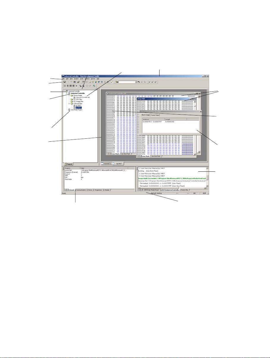
2.1 User Interface
The FDT Graphical User Interface is a Windows® application that presents a work environment, which
allows the user to program FLASH memory.
Menu Bar
Tool Bar
Workspace
Active
Project
Additional
Project
Editor
window
Flash Properties
window (Docked)
Workspace
window
Device Image
Figure 2-1 FDT Graphical User Interface
Title Bar
Status Bar
Files open
in Hex
Editor
Hex Editor
Address Column
S-Record
Properties
Dialog
Output
window
4
Page 21
2.1.1 Menu bar
Commands are grouped into related areas on the Menu bar as indicated by the menu titles. Using the
mouse the user can select a command operation, invoke a dialog box or a window to interact with the
system. Clicking the left mouse button on a menu title will pull down that menu, from which a selection
can be made.
If a menu item does not perform an action directly, but instead displays a dialog box or window for
further user interaction, then its name is appended with an ellipsis (three dots, ...).
Figure 2-2 Menu Ellipsis
If a menu item can also be invoked by pressing a hot key (a combination of keys), then the hot key is
displayed to the right of the item.
If a menu item toggles a feature ON or OFF then a check mark (9) will be displayed next to its text
when it is ON:
Figure 2-3 Checked Menu Items
5
Page 22
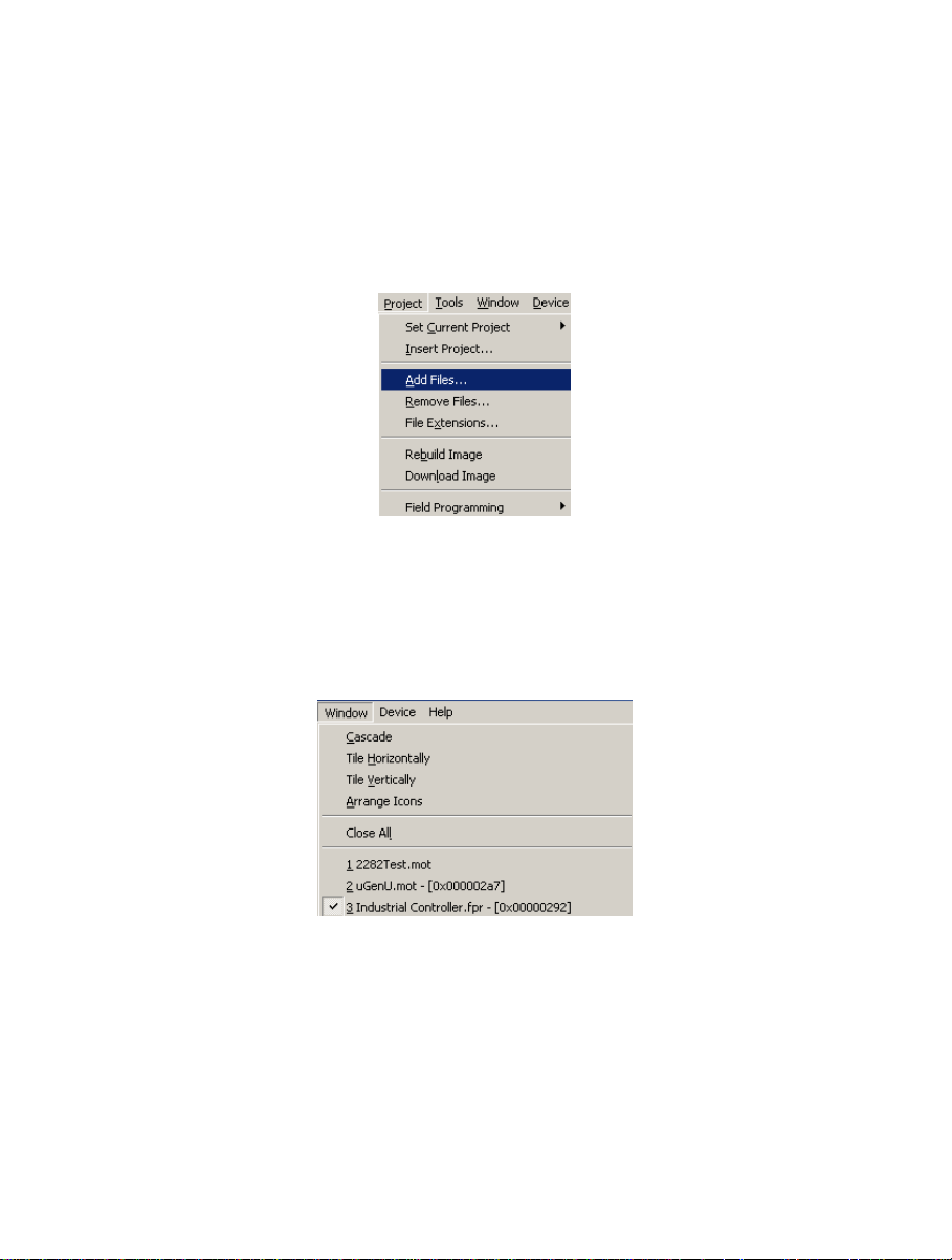
If a menu item has the symbol (8) next to it then a cascading or hierarchical menu is available.
Clicking on the menu item will reveal the cascading menu:
Figure 2-4 Cascading Menus
Menus can also be selected directly from the keyboard by pressing the ALT key followed by the
corresponding key of the underlined letter or number for the menu item that the user wants to select,
e.g. press ALT+F, S in sequence to Save the active file ([F
ile->Save]).
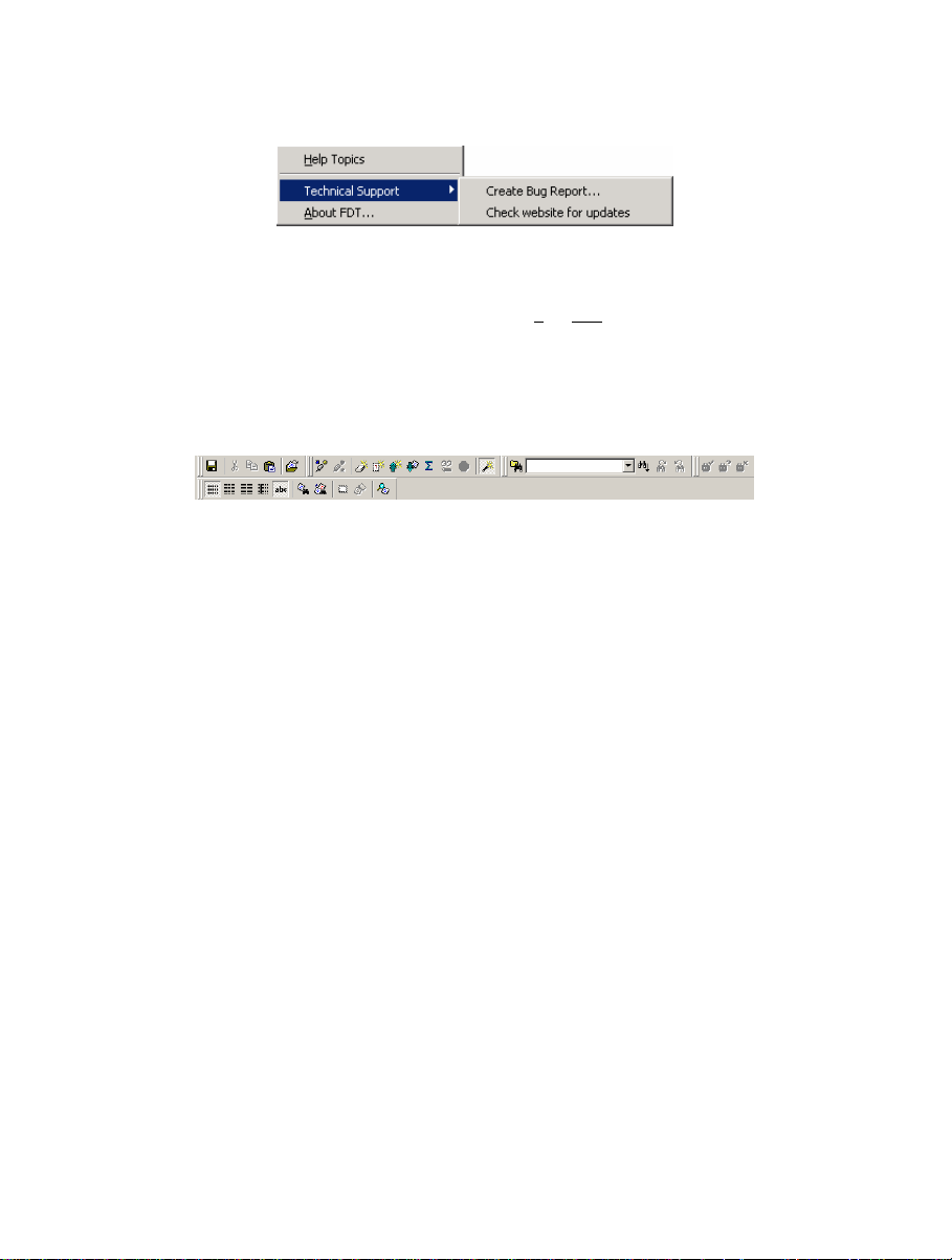
2.1.2 Toolbars
FDT has several toolbars located below the Menu bar. This provides quick access to FDT features by
clicking the respective button with the mouse.
Figure 2-5 FDT Toolbars
The buttons on each toolbar are arranged in associated groups.
To find out the function of the button, move the mouse over the button and a hint will be displayed next
to the button and in the status bar.
The toolbar buttons can be customised to provide a button for the majority of the features available in
FDT and can be arranged in an order that the user finds convenient.
For more details about changing the arrangement of the toolbar buttons and a detailed description of
each button’s function, see Chapter 6 .
6
Page 23

Edit toolbar
Save File
Cut
Copy
Paste
Open an S-Record
Save File – saves the active file.
Cut – cuts data to the clipboard.
Copy – copies data to the clipboard.
Paste – pastes data from the clipboard.
Open an S-Record – Opens an S-Record or data file.
Figure 2-6 Edit Toolbar
7
Page 24

FDT toolbar
Connect
Disconnect
Erase Blocks
Blank Check
Upload
Download Active File
Checksum
Go from Address
Cancel
Configure Flash Project
Figure 2-7 FDT Toolbar
Connect - connects the device to the interface.
Disconnect - disconnects the device from the interface.
Erase Blocks - launches the ‘Erase Block’ dialog box to erase all or individual blocks of the device
FLASH memory.
Blank Check - checks whether or not the FLASH section of the target device is blank.
Upload - launches the ‘Upload Image’ dialog box to allow data to be obtained from the target device.
Download Active File - downloads the file which is active in the hex editor.
Checksum – returns a checksum of the data in the FLASH.
Go from Address – launches a dialog to select the address to execute from.
Cancel – Cancels the current FLASH operation.
Configure Flash Project - launches the ‘Project Properties’ dialog box (or the Project Wizard if the
project is not yet configured).
8
Page 25

S Record toolbar
View as Bytes
View as Words
View as DWords
Align view to 8 bytes
Toggle ASCII
Find
Find and Replace
Create Selection
Fill Selection
Properties
Figure 2-8 S Record Toolbar
View as Bytes - view the file data as 8 bit bytes.
View as Words - view the file data as 16 bit words.
View as DWords - view the file data as 32 bit double words.
Align view to 8 bytes - data is displayed on each line as 8 bytes. The number of bytes that can be
accommodated on each line is dependent upon the size of the window.
Toggle ASCII - turns ASCII data ON or OFF
Find - launches the ‘Find’ dialog box.
Find and Replace - launches the ‘Replace’ dialog box.
Create Selection - selects a block of the specified size in the active file.
Fill selection - launches the ‘Fill’ dialog box.
Properties – launches a dialog with information about the active file.
9
Page 26
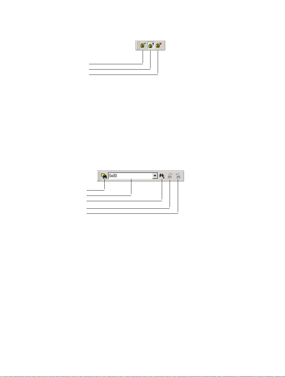
QzROM toolbar
Automatic Protection
Query Protection
No Protection
Figure 2-9 QzROM Toolbar
Automatic Protection – Set QzROM security protection automatically on disconnect.
Query Protection – Ask the user whether to set QzROM security protection on disconnect.
No Protection – Never set QzROM security protection on disconnect.
NB – setting the protection will stop any further connections to that particular target device
Search toolbar
Find in Files
Data
Find
Find Next
Find Previous
Figure 2-10 Search Toolbar
Find in Files – finds selected data in selected files.
Data – is used for the searches.
Find – locates data in active file.
Find Next – locates next occurrence of search criteria.
Find Previous - locates previous occurrence of search criteria.
2.1.3 Status Bar
The Status Bar is located at the bottom of the FDT application window. It provides the user with
information about what the application is doing.
The left section of the Status Bar describes the action of the Toolbar items as the mouse arrow is
positioned over a button, as well as displaying operation status information.
10
Page 27
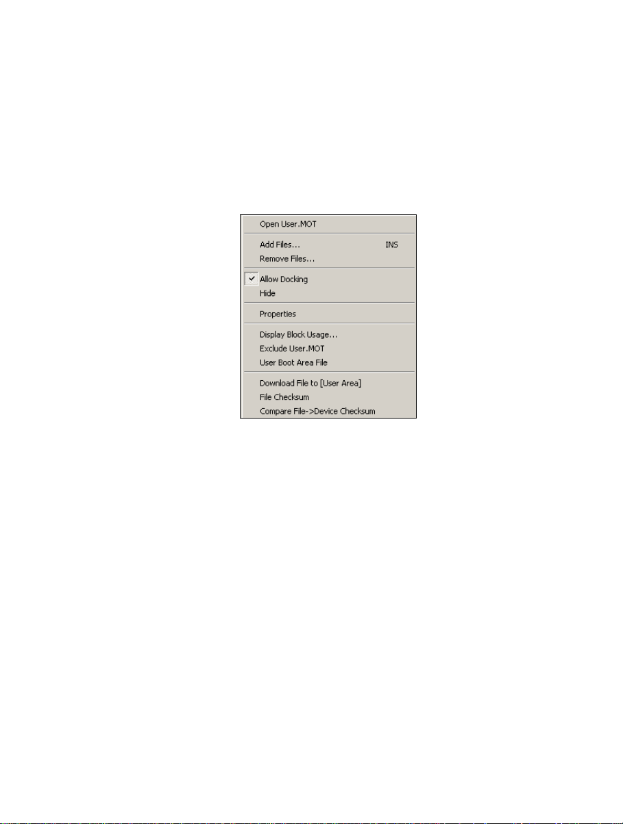
When an action is being performed, a progress bar is displayed to show the progress of the current
operation.
The last section of the bar indicates the state of the toggling keyboard keys such as the Caps Lock,
Insert and Number Lock keys.
2.1.4 Pop-up menus
Many windows have local pop-up menus in order to make commonly used features easier to access.
These menus are invoked by clicking the right mouse button in the window (or pressing SHIFT+F10)
and then selecting the required menu option. An example pop-up menu is:
Figure 2-11 Pop-up Menu
The contents and operation of specific pop-up menus are explained in detail in the description of each
FDT window, see the Chapter 8 , Windows.
2.2 Help
FDT has a standard Windows® help system. This provides on-line information for using the system.
Help can be invoked by pressing the F1 key or via the Help menu.
11
Page 28

2.3 Hot Keys
There are various hot keys for frequently used operations. These are as follows by category:-
Description
Help
Help F1
File Commands
C
Open S-R
Save Al
ave Ctrl+S
S
Ex
Edit Commands
U
R
Cut
C
aste Ctrl+V
P
Select A
ind Ctrl+F
F
Find I
Re
Tools Commands
Login Ctrl+Shift+U
Simple Interface Commands
Login Ctrl+Shift+U
View
Work
Ou
Window
View as A
View as B
View as W
View as D
Align to 8
Hot Key
lose File Ctrl+F4
ecord Ctrl+R
l Ctrl+Shift+H
it Alt+F4
ndo Ctrl+Z
edo Ctrl+Y
Ctrl+X
opy Ctrl+C
ll Ctrl+A
n Files F4
place Ctrl+H
space Alt+K
tput Alt+U
SCII Alt+A
ytes Alt+1
ord Alt+2
word Alt+4
Bytes Alt+8
12
Page 29

Description
Hot Key
Device
onnect Ctrl+Alt+C
C
rase Flash Blocks Ctrl+Alt+E
E
lank Check Ctrl+Alt+B
B
pload Image Ctrl+Alt+U
U
oad Active File Ctrl+Alt+P
Downl
Flash Checks
o From Address Ctrl+Alt+G
G
Can
Configure Flash P
um Ctrl+Alt+S
cel Operation Ctrl+Break
roject Alt+Shift+R
Data File
Suppress request to save changes to a
Hold Shift key when closing data file
data file when closing it (do not save
changes)
13
Page 30

14
Page 31

Chapter 3 Using FDT
3.1 Quickstart
The stages required in order to program a device are as follows:
1) Start FDT by selecting ‘Start’->‘Programs’ -> ‘Renesas’ -> ‘Flash Development Toolkit 3.05’, then
the ‘Flash Development Toolkit 3.05’ shortcut [see section 3.3]
2) Create a Workspace and Project [see section 3.4.1]
3) Configure the Project using the Flash Project Wizard (select device, kernel, port, mode etc) [see
sections 3.4.2 to 3.4.8 or section 3.5 for Generic Boot]
4) Add the file or files that you want to download to the project [see sections 0/8.2.2/3.7]. You can now
download individual files by right clicking on them in the Workspace Window, or merge multiple files
into a device image (using the Project-> Rebuild Image menu item) and download that (using the
Project-> Download Image menu item).
Alternatively, to start in FDT Basic Simple Interface Mode:
1) Select ‘Start’->‘Programs’ -> ‘Renesas’ -> ‘Flash Development Toolkit 3.05’, then the ‘Flash
Development Toolkit 3.05 Basic’ shortcut [see section 3.3]
2) Configure the settings using the Wizard (select device, kernel, port, mode etc) [see sections 3.4.2 to
3.4.8 or section 3.5 for Generic Boot]
3) Select the flash area that you want to program (User Area or User Boot Area).
4) Select the file to program for each enabled area
5) Select the Program Flash Button.
6) Disconnect when programming is completed
3.2 Background Information
3.2.1 What are the User Area, User Boot Area and Data Areas?
The normal area of (internal) flash for Renesas devices, for user programs is known as the User Area.
This is where the code is stored which gets executed when the device is reset into User Mode. The User
area can normally be programmed from a Boot Mode or User Mode connection.
On some devices there is an additional area of flash known as the User Boot Area. This is where the
code is stored which gets executed when the device is reset into User Boot Mode. The User Boot Area
tends to be much smaller than the User Area and is typically used for storing an alternative boot stub,
for setting up communication via some other communications medium / protocol. Normally, the User
Area and the User Boot Area both start at the same address – this is possible because only one is ever
mapped into the memory map at one time. It is only possible to program the User Boot Area from Boot
Mode - not from User Mode.
On some devices there is an additional area of flash known as the Data Area. This area normally
resides at the other end of the memory map to the User Area, and unlike the case of the User Boot
Area, the Data Area is not contiguous with the User Area and always exists in the memory map.
15
Page 32

3.2.2 What is the difference between Boot Mode and User Mode?
The Renesas Flash devices have different modes of operation which are controlled by the state of the
mode pins when the device is brought out of reset. Most devices have an asynchronous serial Boot
Mode and a User/User Program Mode.
Generally, (asynchronous serial) Boot Mode connections, start with an autobaud – sending
synchronisation data packets to setup initial communications at a given baud rate. Additionally, for
most devices, the entire flash will be erased as part of the connection process, thus preventing any
Intellectual Property held on the device from being read from Boot Mode.
For a User Mode connection, the device must already be programmed with some code which talks to
FDT and allows programming. Most kernels are supplied with a User Mode micro kernel and test
program (*usually called “uGenU.mot” and “xxxxtest.mot”). These files provide a
demonstration of User Mode programming and must be programmed into the device and be executing
before FDT tries to connect in User Mode. User Mode does not normally force an erase of the flash
during the connection process and does not autobaud to setup initial communications. The
demonstration User Mode test programs have the required Bit Rate Register value compiled into them
for setting up initial communications at 9600 baud; hence User Mode kernels need to be rebuilt for
different clock frequencies.
*Note that where the files are to be used as part of an embedded monitor, the User Mode kernel files may be also output as
binary files (.cde) without the reset vector populated. Some kernels use o nly a single file for the User Mode test program (e.g.
Protocol C kernels).
3.2.3 What is the difference between User Mode and User Program Mode?
Some devices use an additional mode pin to protect the flash from being written or erased by mistake;
this pin is normally known as the “Flash Write Enable” pin (FWE) if it has to be logic high to allow
programming, or the “Flash Write Protect” pin (FWP) if it has to be logic low to allow programming.
For these devices, this pin distinguishes “User Mode” from “User Program Mode”. An FDT User Mode
connection expects the device to be in User Program Mode at the point of programming and erasing,
and if using the FDM, can reset the device into User Mode to execute the programmed code on
disconnection.
3.2.4 What are “Protocol A”, “Protocol B”, “Protocol C” and “Protocol D” Kernels?
“Protocol A” - For some 0.8μm, 0.6μm and 0.35μm flash devices using FDT 1.5 style kernels.
These are legacy kernels that are not supported and not included in the FDT installer. Protocol
A kernels are not available in the Japanese versions of FDT. Protocol A kernels support use of
the UPB but not the FDM. The kernel needs to be rebuilt for different crystal frequencies in
Boot and User Modes, and for changing the PMODE pin if using the UPB. Please refer to the
documentation supplied with the kernels for additional information.
“Protocol B” – For 0.35μm devices. These support the FDM but not the UPB.
Boot Mode - The kernel (made up of the Boot Mode Micro Kernel, Boot Mode Main Kernel,
and the Write and Erase modules) is held on the PC and downloaded as required. The Boot
Mode kernel does not need to be rebuilt for different crystal frequencies; this information is
stored in the FDT project and downloaded at runtime and initial communication is achieved by
the autobaud (where FDT sends 0x00 data until the device synchronises with it).
User Mode – The User Mode Test Program and User Mode Micro-Kernel need to be already
programmed and executing on the device. The initial Bit Rate Register value is held in the
16
Page 33

‘gentest.h’ file and is compiled into the User Mode Test Program; this allows the kernel
initialise the serial communications interface to 9600 baud. If the clock frequency changes
from the default supplied value, the initial Bit Rate Register setting in ‘gentest.h’ [normally
MA_BRR_SCI or MA_BRR_SCI1] will need to be modified and the kernel recompiled. The
User Mode Main Kernel and the Write and Erase modules are held on the PC and downloaded
as required.
“Protocol C” – For devices with embedded kernels (Currently 0.18μm). These support the FDM but
not the UPB.
Boot Mode – A configuration file is stored on the PC which provides FDT with details about
the device, but the kernel (including the Write and Erase modules) resides internally on the
device. There is no need to rebuild anything for different clock frequencies in Boot Mode; this
information is stored in the FDT project and downloaded at runtime and initial communication
is achieved by the autobaud (where FDT sends 0x00 data until the device synchronises with
it).
User Mode – Some boards are supplied with a User Mode kernel. Similarly to the Protocol B
User Mode kernels, User Mode Kernel needs to be already programmed and executing on the
device. The initial Bit Rate Register value is held in the ‘gentest.h’ file and is compiled into
the User Mode Test Program; this allows the kernel initialise the serial communications
interface to 9600 baud. If the clock frequency changes from the default supplied value, the
initial Bit Rate Register setting in ‘gentest.h’ [normally MA_BRR_SCI or MA_BRR_SCI1]
will need to be modified and the kernel recompiled. The main difference to the Protocol B
User Mode Kernels is that the Write and Erase modules are held internally on the device.
“Protocol D” – For R8C and former Mitsubishi family devices (eg. M16C, M32 etc).
The E8 and FoUSB boards can be used with some Protocol D devices. The kernels are internal
to the device, but FDT uses configuration files to store information about the device
characteristics.
3.2.5 What are the fcf and fdm files, can I edit them?
Stored alongside the other kernel files, the .fcf (Flash Configuration File) and .fdm (Flash Development
Module) files hold details about the device and kernel. Each supported device in each kernel directory
has its own .fcf and .fdm file. Information such as the RAM size, Flash size, Erase Block Register
details, default baud rate and default crystal frequency is stored in the fcf file and details about the
allowed pin settings for the FDM is stored in the FDM file. Each of these files is protected with a
checksum, so editing will render them invalid and FDT will detect this. Upon detection of an invalid
checksum an fcf or fdm file FDT will warn the user but will not prevent use of the modified files.
3.2.6 Can I use FDT if I do not have Local Machine Administrator rights for my PC?
Yes, but only once it is installed and configured. To install FDT and for various configuration tasks,
you must have local administrator rights; this is because some settings are stored in the
HKEY_LOCAL_MACHINE registry area. Once FDT is installed and configured you will be able to
use it with certain limitations. Configuration tasks such as adding new kernel entries to the registry so
that they will be available in the Project Wizard in future requires Local Machine Administrator rights.
This includes adding the Prior Generic Device entry (an administrator must first connect to the Generic
Device to allow the Prior Generic Device entry to be created. Additionally the FDT Advanced Setup
utility which is used for changing settings such as fine tuning of timeouts, requires the Local Machine
17
Page 34

Administrator rights to save the settings. Password administration also requires Local PC Administrator
rights.
3.2.7 How do I recompile a kernel?
It is recommended that the original kernel is copied to another directory and that this copy is edited,
thus leaving the original kernel unmodified. When using the kernel for the first time, you will need to
browse to the alternate location to find the fcf file.
If the kernel has been written using Hew, there will be a Hew workspace file in the project subdirectory
of the kernel. This should be opened from Hew.
If the kernel has been written based upon compilation from the command line, you will need to run the
buildall.bat file from a Dos shell session after setting up the environment variables for the compiler so
that it can be run from the command line. Please refer to the compiler manual for full details of how to
do this. An example environment batch file used to set the environment settings for the Renesas H8
compiler version 4.0a is shown below:
Setenv.bat:
SET CH38=C:\hew\tools\Renesas\h8\4_0_A\INCLUDE
PATH=%PATH%;C:\hew\tools\Renesas\h8\4_0_A\bin
set DOS16M= @1M-31M
SET CH38TMP=c:\TEMP
Notes:
From some operating systems (eg Windows 2000), cmd.exe should be used rather than command.com.
The above batch file should be modified to reflect the path of your compiler.
Ensure that the specified temporary directory exist s and is writeable.
3.2.8 How do I use the supplied demonstration User Mode Kernels?
To use the demonstration User Mode kernels, you must first add the User Mode Micro Kernel and User
Mode Test Program from the kernel directory (“uGenU.mot” and “xxxxtest.mot”) to a Boot
Mode Project and build the User Area Device Image. Next, connect in Boot Mode and program the
image to the device, disconnect and reset the device into User Mode. Create another project in the
workspace, but this time set it as a User Mode Connection Type, and connect in User Mode. FDT will
start communications with the User Mode Test Program at 9600bps and then change to the baud rate set
in the project. Note that the device does not automatically erase during connections in User Mode. It is
not possible to reprogram the FLASH whilst the reprogramming code is executing from the FLASH so
all of the kernel modules needed to keep the connection to FDT are copied into the RAM to leave the
FLASH ROM available for reprogramming. Because of this, it is possible to erase the entire flash and
reprogram it in user mode, but note that if the device is reset after erasure and before it is
reprogrammed, it will not be possible to reconnect in User Mode until the device has had the User
Mode Micro Kernel and User Mode Test Program reprogrammed into it Boot Mode.
18
Page 35

3.2.9 Can I modify the User Mode kernels to work for a different clock frequency?
It is recommended that the original kernel is copied to another directory and that this copy is edited,
thus leaving the original kernel unmodified. When using the kernel for the first time, you will need to
browse to the alternate location to find the fcf file.
The User Mode kernels need to be rebuilt if a different clock frequency is going to be used. The initial
Bit Rate Register value is held in the ‘gentest.h’ file and is compiled into the User Mode Test Program;
this allows the kernel initialise the serial communications interface to 9600 baud. If the clock frequency
changes from the default supplied value, the initial Bit Rate Register setting in ‘gentest.h’ [normally
MA_BRR_SCI or MA_BRR_SCI1] will need to be modified and the kernel recompiled. Refer to the
device hardware manual for details of how to calculate the Bit Rate Register value.
19
Page 36

3.3 Starting FDT
3.3.1 Starting FDT without Security or Simple Interface Mode enabled
®
To start FDT, open the ‘Start’ menu of Windows
Development Toolkit 3.05’, then the ‘Flash Development Toolkit 3.05’ shortcut. The ‘Welcome’ dialog
box will open by default.
Figure 3-1 Welcome Dialog
To create a new workspace, select ‘Create a new Project Workspace’ and click the ‘OK’ button (see
section 3.4.1 for details). To open a recent workspace, select ‘Open a recent project workspace’ and the
workspace to be opened from the list box. To open an existing workspace which is not in the list of
recently used workspaces, select ‘Browse to another project Workspace’. Finally, click the ‘OK’ button.
and select ‘Programs’ -> ‘Renesas’ -> ‘Flash
3.3.2 Starting FDT in Basic Simple Interface Mode
®
To start FDT in Basic Simple Interface Mode, open the ‘Start’ menu of Windows
and select
‘Programs’ -> ‘Renesas’ -> ‘FLASH Development Toolkit 3.05’, then the ‘Flash Development
Toolkit 3.05 Basic’ shortcut. The previous FDT Basic settings will be restored, and new settings can be
entered by selecting the Options->New Settings… menu item.
3.3.3 Starting FDT by double clicking on a workspace file
®
FDT can be started by double clicking on a workspace file from Windows
Explorer. This will cause
FDT to load the selected workspace upon start up.
3.3.4 Starting FDT by double clicking on a data file
®
FDT can be started by double clicking on a registered data file from Windows
Explorer (if this default
option was not unselected during installation). This will cause FDT to load the selected data file upon
start up.
20
Page 37

3.3.5 Starting FDT by double clicking on a w4f script configuration file
FDT can be started by double clicking on a .w4f script configuration file from Windows
®
Explorer.
This will cause FDT to start in Wait For Script mode and load the selected configuration.
3.3.6 Starting FDT with Simple Interface Mode enabled
If FDT was exited from Simple Interface Mode (see section Chapter 9 ) FDT will return straight back to
that mode.
3.3.7 Starting FDT with Access Rights password security enabled
If the Access Rights password security has been enabled, FDT will display the login dialog before
allowing the workspace to be opened. See Chapter 5 for further details.
3.3.8 Starting FDT by double clicking on a .fpf packaged project file
®
FDT can be started by double clicking on a .fpf packaged project file from Windows
Explorer. This
will cause FDT to unpackage the project and start in Simple Interface Mode.
3.3.9 Starting FDT from the command line
3.3.9.1 Opening data files from the command line
"<FDT path>\FDT.exe" /DISCRETESTARTUP "osre \"< Filename >\""
eg:
"C:\Program Files\Renesas\FDT3.05\FDT.exe" /DISCRETESTARTUP "osre \"C:\Program
Files\Renesas\files\myfile.mot\""
®
This is the method used when an FDT data file is double clicked in Windows
Explorer
3.3.9.2 Opening workspace files from the command line
"<FDT path>\FDT.exe" /DISCRETESTARTUP "ow \"<Long Path Workspacename>\""
eg
"C:\Program Files\Renesas\FDT3.05\FDT.exe" /DISCRETESTARTUP "ow \"C:\Program
Files\Renesas\FDT3.05\Workspaces\1234\1234.AWS\""
This is the method used when an FDT workspace is double clicked in Windows
®
Explorer
3.3.9.3 Opening data files from the command line with Access Rights password security
enabled
"<FDT path>\FDT.exe" "arl \"<Username>\" \"<Password>\"" /DISCRETESTARTUP "osre \"<
Filename >\""
eg
21
Page 38

"C:\Program Files\Renesas\FDT3.05\FDT.exe" "arl \"Administrator\" \"password\""
/DISCRETESTARTUP "osre \"C:\Program Files\Renesas\files\myfile.mot\""
3.3.9.4 Opening w4f Script Configuration files from the command line
"<FDT path>\FDT.exe" /DISCRETESTARTUP "w4fRun \"<filename>\""
eg
"C:\Program Files\Renesas\FDT3.05\FDT.exe" /DISCRETESTARTUP "w4fRun \"C:\Program
Files\Renesas\FDT3.05\myconfig.w4f\""
®
This is the method used when an FDT Script Configuration file is double clicked in Windows
Explorer
3.3.9.5 Opening w4f Script Configuration files from the command line with Access
Rights password security enabled
"<FDT path>\FDT.exe" "arl \"<Username>\" \"<Password>\"" /DISCRETESTARTUP "w4fRun
\"<filename>\""
eg
"C:\Program Files\Renesas\FDT3.05\FDT.exe" "arl \"Administrator\" \"password\""
/DISCRETESTARTUP "w4fRun \"C:\Program Files\Renesas\FDT3.05\myconfig.w4f\""
3.3.9.6 Starting FDT Basic Simple Interface Mode from the command line
22
"<FDT path>\FDT.exe" /DISCRETESTARTUP "SimpleInterfaceMode /u \"<User Area
Filename>\" /b \"<User Boot Area or Data Area Filename>\""
eg
"C:\Program Files\Renesas\FDT3.05\FDT.exe" /DISCRETESTARTUP "SimpleInterfaceMode /u
\"c:\upload1.mot\" /b \"c:\upload0.mot\""
Note that the /u <User Area Filename> and the /b <User Boot Area> are optional. Additionally,
adding /r causes the last settings to be restored and the configuration Wizard will not be displayed.
Page 39

3.4 Creating a New Workspace and Project
When FDT is started in full mode (not FDT Basic Simple Interface Mode), a workspace and project must be
opened or created. See Chapter 10 Basic Simple Interface Mode for details on programming without setting
up a workspace and project.
3.4.1 New Project Workspace
Enter the workspace name (the project name is the same by default), then click the ‘OK’ button. If you
wish to change or create a directory, input a directory name or use ‘Browse...’ button.
Figure 3-2 New Workspace
23
Page 40

3.4.2 Choose Device and Kernel (not Generic Boot*)
Select the device you wish to use from the drop-down list. It is possible to have more than one kernel
option displayed, and double clicking on a kernel will open an optional “readme.txt” file that has
information about the kernel (such as the device, version number and the compilers it was created with).
Select the required kernel from the displayed list, or if you have an alternative kernel elsewhere, which
is not in the list, select ‘Other...’ to specify the kernel Flash Configuration File (.fcf).
*For connection to a Generic Boot Device see the “Configuring a Project for a Generic Boot Device”
section.
24
Figure 3-3 Device and Kernel Selection
Page 41

3.4.3 Communications Port
Select the port (and interface if available) from the drop-down list, then click the ‘Next’ button. Note
that in addition to the serial ports, there is also an option to use the FDM (USB interface board). For
some kernels there are also other port options, such as USB Direct (eg. for the 2215UF), E8, E8Direct
and FoUSB. For Protocol A (legacy) kernels the ‘HMSE UPB’ interface is available in addition to
Direct Connection.
Figure 3-4 Communications Port
25
Page 42

3.4.4 Device Settings
Enter values for the device settings; enter the input clock, then select the main and peripheral clock
multipliers from the drop-down lists, and click the ‘Next’ button.
Supplementary:
1. Clock Setting
Allow selection of the device external clock (default) or one or more of the device internal clock
speeds.
2. CPU Crystal Frequency
Enter the frequency of the CPU clock or the crystal generator. This can be specified up to 4 decimal
places. The target device, the kernel and the Clock Mode determine the valid range.
3. Clock Mode
If enabled, select the required value from the drop-down list.
4. Multiplier for CKM
If enabled, select the input clock multiplier for the master (system) clock. The available options
depend upon the target device, the kernel and the Clock Mode.
5. Multiplier for CKP
If enabled, select the input clock multiplier for the peripheral clock. The available options depend
upon the target device, the kernel and the Clock Mode.
26
Figure 3-5 Device Settings
Page 43

Note To enter the clock mode, input clock, and multipliers, refer to the device hardware manual
and/or the target board manual to confirm the values required.
3.4.5 Connection Type
Select whether the connection is for Boot Mode or User Mode in the ‘Connection Type’ dialog.
Additionally, for a connection to a kernel that is still running on the device from a previous session,
select the ‘Kernel already running’ check box. Next, select the communication speed (bps) if the default
value is not correct or not present. Speeds where the target error rate is greater than 4%, or the
FDM\E8Direct error rate is greater than 0% are automatically removed from the recommended list.
When using the FDM\E8Direct the ‘User Specified’ connection speed option is enabled; when selected,
this allows the user to specify a non-standard baud rate. The error rate will be displayed – this takes into
account the target peripheral clock rate, the target Bit Rate Register calculation formula, and the
FDM\E8Direct characteristics.
Click the ‘Next’ button to continue.
Figure 3-6 Connection Type
Note that ‘Use Default’ is designed for use with the Renesas Evaluation Board or Evaluation
Development Kits. Uncheck this to allow manual selection of the bit rate.
27
Page 44

3.4.6 Programming Options
Select the protection level for programming the FLASH ROM and the messaging level, then click the
‘Finish’ button, or if the FDM\E8Direct was selected, click ‘Next’ to continue.
Figure 3-7 Programming Options
3.4.7 FDM\E8Direct Pin Settings
[Only if the FDM or E8Direct is selected] Select the ‘Operating Mode’ and ‘Clock Mode’ and if ‘User
Defined’, set the pin settings. [For ‘Boot Mode’ projects set the ‘Boot Mode Outputs’ and the ‘Boot
Mode Setting’ for the required mode, for ‘User Mode’ projects set the ‘User Mode Outputs’, ‘User
Mode Setting’ and the ‘User Program Mode Setting’ for the required mode.] Click the ‘Next’ button to
continue. “*Mode Outputs” sets which pins are driven, “*Mode Setting” sets whether output pins are
driven High (checked) or Low (Unchecked).
Notes: Setting the mode pins using the FDM or E8Direct requires caution. Please confirm the pin
settings with the hardware manual even if a default setting is available. Should you be using the
E8Direct then a message-box will also appear requesting confirmation of this warning. Note that in
some devices, changing the mode pin setting changes the maximum supply voltage.
28
Page 45

Figure 3-8 FDM Pin Settings
Figure 3-9 E8Direct Pin Settings
29
Page 46

3.4.8 Reset Pin Settings
[Only if the FDM or E8Direct is selected] Select the ‘Operating Mode’ and ‘Clock Mode’ and if ‘User
Defined’, set the Reset pin settings. Set the ‘Reset Outputs’ and the ‘Reset Setting’ for the mode
required immediately after disconnection. Click the ‘Finish’ button. “*Mode Outputs” sets which pins
are driven by the FDM, “*Mode Setting” sets whether output pins are driven High (checked) or Low
(Unchecked).
Notes: Setting the mode pins using the FDM or E8Direct requires caution. Please confirm the pin
settings with the hardware manual even if a default setting is available. Note that in some devices,
changing the mode pin setting changes the maximum supply voltage.
30
Figure 3-10 FDM RESET Pin Settings
Page 47

Figure 3-11 E8Direct RESET Pin Settings
31
Page 48

3.5 Configuring a Project for a Generic Boot Device
It is also possible to connect to a Generic Boot Renesas Device - where you do not need a kernel or
configuration file installed, instead FDT extracts the required information from the device itself. Because of
this, the device must be connected and set into Boot Mode at the time you create the project. If a Generic
Boot device is selected, then a series of screens appear displaying the results of the inquiry functions, you
will be required to make selections about the device and clock mode (one boot program may be shared for
multiple devices).
3.5.1 New Project Workspace
Enter the workspace name, then click the ‘OK’ button. (Specify whether or not a directory is to be
created and a location.)
32
Figure 3-12 New Workspace
Page 49

3.5.2 Generic Boot - Choose Device and Kernel
Select ‘Generic Boot Device’ and click ‘Next’
Figure 3-13 Generic Boot Device Selection
3.5.3 Generic Boot - Communications Port
Select the port (and interface if available) from the drop-down list, then click the ‘Next’ button.
33
Page 50

Figure 3-14 Communications Port
3.5.4 Generic Boot - FDM Pin Settings [FDM connection only]
If the FDM is selected the following screen will be shown. Set the mode pin settings required to place
the device into Boot Mode. Click ‘OK’ to continue.
Figure 3-15 FDM Generic Device Pin Settings
Note Setting the mode pins using the FDM requires caution. Please confirm the pin settings with the
hardware manual even if a default setting is available. Note that in some devices, changing the mode
pin setting changes the maximum supply voltage.
34
Page 51

When the ‘Select USB Device’ Dialog is displayed you must select which FDM unit is to be used to
set up the connection.
Figure 3-16 Select USB Device
3.5.5 Generic Boot - E8Direct Pin Settings [E8Direct connection only]
If E8Direct is selected the following two screens will be shown. The first allows optional power to be
supplied to the target board via the E8 (see also section 3.6.1)
Figure 3-17 E8 Target Power Supply Selection
WARNING: Damage to the target device may occur if the incorrect voltage setting is chosen!
This will be followed by the mode pin settings dialog, required to place the device into Boot Mode.
Click ‘OK’ to continue.
Figure 3-18 E8Direct Generic Device Pin Settings
35
Page 52

Note Setting the mode pins using the E8Direct requires caution. Please confirm the pin settings with
the hardware manual even if a default setting is available. Note that in some devices, changing the
mode pin setting changes the maximum supply voltage.
If the E8 has not yet been restarted as an E8Direct device then the following messages will appear in
the FDT output window:
Preparing for re-enumeration of E8 to E8Direct...
Sending re-enumeration command...
Request sent successfully, closing E8 Comms...
At the same time Windows® will re-enumerate the device (see also Chapter 13 - E8Direct).
When the ‘Select USB Device’ Dialog is displayed you must select which E8Direct unit is to be
used to set up the connection.
Figure 3-19 Select USB Device
3.5.6 Generic Boot - Confirmation
FDT then waits for you to confirm that the device is connected and powered, and if not using the FDM
or E8Direct, in Boot mode. FDT will try to connect to the device when you click ‘OK’.
Figure 3-20 Generic Boot Confirmation
After this, FDT displays a dialog that displays the boot progress. At various points during the Generic
Boot process, the user is required to select or confirm details of the device; see below for details.
36
Page 53

3.5.7 Generic Boot – Select Device
Because some devices share a boot program, a list is provided of all those supported. The user should
select the correct device from the list then click ‘OK’.
Figure 3-21 Generic Boot – Device
3.5.8 Generic Boot – Select Clock Mode
Because some devices have a number of Clock Modes, a list is provided of all possible Clock Modes.
The user should select the correct Clock Mode from the list then click ‘OK’. Please check with the
hardware manual / target board manual to ensure that the correct mode is chosen.
37
Page 54

Figure 3-22 Clock Mode
3.5.9 Generic Boot – Setup Complete
Having selected the Clock Mode, the Generic wizard completes as below.
Figure 3-23 Generic Boot setup complete
The Project Wizard will then continue through the remaining pages
38
Page 55

3.5.10 Generic Boot – Device Settings
Please Refer to Section 3.4.4
3.5.11 Generic Boot - Connection Type
Please Refer to Section 3.4.5
3.5.12 Generic Boot – Programming Options
Please Refer to Section 3.4.6
3.5.13 Generic Boot – Reset Pin Settings [FDM connection only]
Please Refer to Section 3.4.8
3.5.14 Generic Boot – Reinterrogate on connect option
The ‘Programmer’ tab of the ‘Flash Properties’ dialog allows the user to configure whether FDT should
reinterrogate the Generic device on each connection. The default is set to ‘No’, so after a connection
has been established once, FDT re-uses the data collected from the initial inquiry functions. If this
option is changed to ‘Yes’, FDT will interrogate the device for the device details each time it connects
in Boot Mode. This means that one Generic Boot project will work with any Generic Boot Device.
3.5.15 Prior Generic Device
Selection of the ‘Prior Generic Device’ device allows a connection to the last device configured using
‘Generic Boot Device’. It uses the .fcf file which was generated when first connecting using ‘Generic
Boot Device’.
3.6 Connecting to the device
This is achieved by selecting the ‘Device->Connect to Device’ menu item, using the Ctrl-Alt-C hotkey, or
clicking the Connect toolbar button. If a flash operation (Upload, Download, Blank Check, Checksum etc)
is selected before a connection is established, FDT will automatically perform a connect operation first.
3.6.1 E8 USB Connection
When connecting for the first time since opening the workspace, and using the E8 USB interface board,
a dialog will be displayed to allow selection of whether the E8 should supply power to the target, and at
which voltage level. The selected power level will be supplied to the target device when connecting and
switched off when disconnecting. The power level selection will be remembered until the workspace is
closed.
WARNING: Damage to the target device may occur if the incorrect voltage setting is chosen!
39
Page 56

Figure 3-24 E8 Target Power Supply Selection
3.6.2 ID Check Dialog
For devices which support the ID Check for unlocking the device, the ID check dialog will be displayed
if the devices are not unlocked with automatic unlocking. The Browse button allows selection of a mot
or an ID file to collect the ID codes from.
Figure 3-25 ID Check Dialog
3.7 Programming the Data to the FLASH ROM
3.7.1 Programming an individual file to the User Area (normal flash area)
1. Select [Project->Add Files...] or press the INS key to add the file to be downloaded to the
project.
2. Click the right mouse button on the file displayed in the workspace window, and select
‘Download File’. Programming will be completed when ‘Image successfully written to device’
is displayed in the output window.
3.7.2 Programming multiple files to the User Area (normal flash area)
1. Add all the required target files to the project by selecting [Project->Add Files...] or pressing
the INS key. Note that multiple files can be added at once from the ‘Add File(s)’ dialog.
2. Build the device image for the User Area (create a file which is the result of merging all of the
included target files) by selecting the menu item:
[Project->Rebuild Image]
3. Click the right mouse button on the Device Image file (<ProjectName>.ddi) displayed in the
workspace window, and select ‘Download Image’ (or select the menu item
[Project->Download Image] )
40
Page 57

4. Programming is complete when ‘Image successfully written to device’ is displayed in the
output window.
3.7.3 Programming an individual file to the User Boot Area
1. Select [Project -> Add Files...] or press the INS key to add the file to be downloaded to the
Project.
2. Click the right mouse button on the file displayed in the workspace window, and select ‘User
Boot Area File’ to mark this file as being for the User Boot Area.
3. Click the right mouse button on the file displayed in the workspace window, and select
‘Download File to [User Boot Area]’. Programming will be completed when ‘Image
successfully written to device’ is displayed in the output window.
3.7.4 Programming multiple files to the User Boot Area
1. Add all the required target files to the project by selecting [Project->Add Files...] or pressing
the INS key. Note that multiple files can be added at once from the ‘Add File(s)’ dialog.
2. Click the right mouse button on each file displayed in the workspace window which is
destined for the User Boot Area, and select ‘User Boot Area File’ to mark it as being for the
User Boot Area.
3. Build the device image for the User Boot Area (create a file which is the result of merging all
of the included target files) by selecting the menu item: [Project->Rebuild Image]
4. Click the right mouse button on the Device Image file (<ProjectName>.ddi) displayed in the
workspace window, and select ‘Download Image’ (or select the menu item
[Project->Download Image] )
5. Programming is complete when ‘Image successfully written to device’ is displayed in the
output window.
3.7.5 Programming some files to the User Area and other files to the User Boot Area
1. Add all the required target files to the project by selecting [Project->Add Files...] or pressing
the INS key. Note that multiple files can be added at once from the ‘Add File(s)’ dialog.
2. Click the right mouse button on each file displayed in the workspace window which is
destined for the User Boot Area, and select ‘User Boot Area File’ to mark it as being for the
User Boot Area.
3. Build the device image for the User Boot Area (create a file which is the result of merging all
of the included target files) by selecting the menu item: [Project->Rebuild Image]
4. Select the menu item [Project->Download Image] )
5. Programming is complete when ‘Image successfully written to device’ is displayed in the
output window for both the User Area and the User Boot Area
41
Page 58

3.8 Erasing Data from the FLASH ROM
1. Select [Device -> Erase FLASH blocks...] to display the ‘Erase Blocks’ dialog box.
2. Select the block(s) to be erased. (When the checkbox is ticked, the block is selected.)*
3. Click the ‘Erase’ button to start erasure.
4. When ‘Erase complete’ is displayed in the output window, erasure is completed.
Figure 3-26 Erase Blocks
*Note To erase all blocks, clicking the ‘Select All’ button will tick every available check box. To erase all non-
blank blocks, clicking the ‘Select Written’ button will tick every associated check box. Ticking the box
of a parent item will toggle the state of all child items. A greyed check-box indicates that only some of
the child items are ticked.
42
Page 59

3.9 Uploading the FLASH ROM Data
1. Display the ‘Upload Image’ dialog box from [Device -> Upload Image...].
either
2. Select the Address tab
3. Enter the start and end addresses, or the start address and length.
4. Click the ‘Upload’ button to start reading.
or
5. Select the Tree tab
6. Select the blocks to be uploaded (corresponding to the erase blocks and\or the device flash areas).
7. Click the ‘Upload’ button to start reading.
When ‘Upload operation complete’ is displayed in the output window and the uploaded data is displayed
in the hex editor, reading is complete.
If the user specifies an Absolute image, the uploaded data will be placed in an image the size of the
FLASH memory at the same address it was uploaded from. Use an Absolute Image if the uploaded data
needs to be added to the project. It is not possible to upload a region outside of the FLASH into an
Absolute Image.
Note When FDT is started in boot mode, the flash memory data has normally already been erased.
Figure 3-27 Upload Image Dialog - Address
43
Page 60

Figure 3-28 Upload Image Dialog – Tree
The Upload via erase block has the same selection functionality as the Erase block dialog itself, i.e.
‘Select All’ will check every block (a complete device upload) and ‘Select Written’ will check the nonblank blocks (an upload of programmed areas).
3.10 Performing a Blank Check
For kernels which support it, a blank check can be performed by selecting the ‘Device->Blank Check’
menu item. This will perform a blank check on all available device areas (e.g. User and User Boot).
3.11 Disconnecting from the device
This is achieved by selecting the ‘Device-> Disconnect’ menu item, or clicking the Disconnect toolbar
button.
3.12 Saving a Workspace
When the [File -> Save Workspace] menu option is selected, the FDT workspace can be saved.
3.13 Closing a Workspace
Select [File -> Close Workspace] to close the FDT workspace. If the workspace or its project has changed,
a dialog box asks if the user wishes to save the project. Select “Yes” if the workspace is to be saved, “No” if
the workspace is not to be saved, and “Cancel” to return to the workspace. If you are prompted to save the
session, then select “Yes”. These prompts can be switched on and off by changing the setting in the
Workspace tab of the [Tools -> Options] dialog.
44
Page 61

3.14 Exiting FDT
To exit FDT, select [File -> Exit], press the Alt + F4 key, or select the ‘Close’ option from the system menu
(the system menu can be opened by clicking the icon in the upper-left are of the title bar).
45
Page 62

46
Page 63

Chapter 4 Wait For Script
4.1 Wait For Script Overview
This mode allows FDT to be automated and controlled by a text file containing a script of commands. Once
in this mode FDT acts as a server which polls for the existence of a file in a predetermined location. Once
this file is found, FDT executes each command in order and can then optionally delete or move the script
file upon completion, so that FDT is ready to look for the next script file. This allows FDT to connect,
program, erase, blank check etc, under the control of an external application, via the use of a simple text file.
The messages in the output window can optionally be echoed to a log file for later analysis and traceability.
Additionally, a status file can be created, which holds information about the state of the current and
previous script processes. This status file can be used by the external application to determine whether the
script has been processed successfully.
To set up FDT Wait For Script, a configuration file needs to be created to specify the search path for the
script file and other parameters such as the settings for the log and status files, and how to handle errors.
4.2 Wait For Script – New Configuration...
This is invoked from the ‘Tools’, ‘Wait For Script’, ‘New Configuration...’ menu.
4.2.1 Script File Page
Figure 4-1 Script File Page
This is the only essential page in the wait for script configuration.
4.2.1.1 Description
This is an optional text description that may be used to describe, e.g. who created the file, why it
was created, what it does, etc. It is not used in any way, other than for display.
47
Page 64

4.2.1.2 Script Path
This is the only mandatory field. This edit box allows the user to set up where to find the script file
to run. This can either be a specific file (e.g. c:\Scripts\MyScript.fsf) or a directory and wildcard
combination (e.g. c:\Scripts\*.fsf).
The ‘File...’ button to the right of the edit field invokes browse dialog to allow the user to navigate
to the file they want to use. The Wildcard... button to the right of the Wildcard edit field invokes a
standard Windows directory selection dialog. If a directory is chosen from this dialog then a
trailing “\*.fsf” (fsf is the default script extension) will also be appended to the path as a
convenience to the user. This field can also be edited manually.
4.2.1.3 Timings
This allows user control over how often FDT polls for the script file and how long FDT should
wait before processing, after finding the script file and having access to it.
4.2.1.4 Save
This saves the FDT Script Configuration file (with the default extension .w4f). FDT will prompt to
ask if you want to execute the saved script immediately.
4.2.2 Log File Page
This is an optional page; leave the fields blank if no log file is required. It can either append to or
overwrite existing files
48
Figure 4-2 Log File Page
4.2.2.1 Log File Directory
Enter the directory that the optional log file should be created in. FDT can insert additional details
into the directory path such as the user name, machine name, date or time by using the %U, %M,
%D and %T delimiters.
Page 65

4.2.2.2 Log File Name
Enter the name of the optional log file. FDT can insert additional details into the file name such as
the user name, machine name, date or time by using the %U, %M, %D and %T delimiters.
4.2.2.3 Save
This saves the FDT Script Configuration file (with the default extension .w4f). FDT will prompt to
ask if you want to execute the saved script immediately.
4.2.3 Status File Page
This is an optional page; leave the ‘Enable status output to file’ checkbox unchecked if no status file is
required. See section 4.7 for details of the contents of the status file.
Figure 4-3 Status File Page
4.2.3.1 Status File Directory
Enter the directory that the optional status file should be created in. FDT can insert additional
details into the directory path such as the user name and machine name by using the %U and %M.
4.2.3.2 Status File Name
Enter the name of the optional status file. FDT can insert additional details into the file name such
as the user name and machine name date or time by using the %U and %M delimiters.
4.2.3.3 Save
This saves the FDT Script Configuration file (with the default extension .w4f). FDT will prompt to
ask if you want to execute the saved script immediately.
49
Page 66

4.2.4 Error Handling Page
This is an optional page.
4.2.4.1 On Script Fail
Abort - leave the ‘On Script Fail’ radio button set to the default ‘Abort’ to cause FDT to abort
processing of further scripts upon encountering an error.
Continue - allows FDT to ignore the fact that the error occurred and continue processing further
scripts.
Run Script - forces FDT to process an error handling script upon encountering an error. The script
file to execute on script fail can be entered in the input box manually or by using the browse
button. Typically a fail script may contain the disconnect command, an alert command and the
abort command.
# Script process ing failure handl in g script example 1
# Disconnect to allow reconnection
Disconnect
# Display a message to the user
Alert output|******************************************************************
Alert output|********** THE CURRENT SCRI PT PROCESSING HAS FAILED **************
Alert output|******************************************************************
Alert output|* * The script which was be ing processed will now be de leted. **
Alert output|* * Please reset the boar d and regenerate the scr ip t to retry **
Alert output|******************************************************************
# Delete the script file which failed
# so that FDT will wait for it to be regenerated before retrying
delete $script
Figure 4-4 Error Handling Page
50
Page 67

# Script process ing failure handl in g script example 2
# Disconnect to allow reconnection
Disconnect
# Display a message to the user
Alert output|******************************************************************
Alert output|********** THE CURRENT SCRI PT PROCESSING HAS FAILED **************
Alert output|******************************************************************
Alert output|** Wait For Script Processing will now be aborted **
Alert output|* * To retry, use ‘Tools’, ‘Wait for Scrip t’ , **
Alert output|* * ‘Run configuration.. .’ an d select the config ur ation **
Alert output|******************************************************************
#Stop script processing
Abort
4.2.4.2 Save
This saves the FDT Script Configuration file (with the default extension .w4f). FDT will prompt to
ask if you want to execute the saved script immediately.
4.3 Wait For Script – Edit Configuration...
This is invoked from the ‘Tools’, ‘Wait For Script’, ‘Edit Configuration...’ menu and allows you to edit the
configuration settings for a given configuration file.
51
Page 68

4.4 Wait For Script – Run Configuration...
This is invoked from the ‘Tools’, ‘Wait For Script’, ‘Run Configuration...’ menu and allows the user to
browse to select the desired Wait For Script Configuration file (.w4f). FDT then enters Wait For Script
mode:
Figure 4-5 Wait For Script execution
4.5 Wait For Script – Script Commands
A script file is nothing more than a text file containing a series of commands that FDT will recognise, one
per line. Each command may also have a series of arguments associated with it, on the same line. By default
these script files will have a “.fsf” extension.
The syntax for a script line is the command, followed by a space, followed by required arguments
(separated by the ‘|’ operator). Optional extra arguments follow these, and can be placed in any order.
Normally a script file should end with the ‘delete $script’ command. This causes FDT to delete the script
once processing is finished, thus preventing the same script file being processed more than once. FDT will
then start looking for the next script file. Alternatively the move command could be used to move the script
file to an alternative directory once completed
52
Page 69

Each script command should be written on a separate line of the text file; FDT will cope with DOS and
UNIX style line breaks (CR or CR LF). File paths within the script file can include drive letters or network
paths (including IP addresses).
4.5.1 Workspace
Description = loads a specified workspace into FDT (Note: a valid workspace and configured project
must be opened to use any of the device-related commands)
Arguments:
<Workspace Path> Required The path to the workspace
Example:
Workspace C:\Workspaces\3069serial\3069serial.AWS
NB: FDT will use the active project from this workspace – there is currently no facility for changing
which is the active project from the script
4.5.2 Connect
Description = connect to a device
Arguments:
<PORT>
“USB”|<USB PID>|<USB BID>
Note that the connection will only be attempted with the project port setting and not to change the port
used to connect. Specification of the port in this command is only to force a failure if the project does
not match this setting, and to suppress the Select Device connection dialog for USB devices by
allowing the PID/BID or FDM and Serial number to be preselected.
Examples:
Connect
Connect USB|0x000D|0
Connect USB|FDM|SN: 93506
Connect COM1
Optional
Optional
If the port specified does not match
the project port settings the command
will fail. For USB direct and FDM
connections this must be set to
“USB”
When using USB it is possible to preempt the Select Device connection
dialog normally seen with these
settings. (If using an FDM the PID
should be set to “FDM” and the BID
should be set to “SN: “ followed by
the FDM’s serial number)
53
Page 70

4.5.3 Download
Description = download the selected project image to the device
Arguments:
“image” Download the device image
<filename>
“user” Download the user image\Download to the user
“userboot” Download the user boot image\Download to the
“both”
“norebuild” Optional Don’t rebuild the image(s) before downloading,
“verify” Optional Perform a readback verify when the download
Example:
Download image|user|norebuild|verify
Download C:\files\MySrecord.mot|userboot
Required
(One of)
Required
(One of)
Download the named file
area
user boot area. This can also be used to
download to the User Area.
Download the user and user boot image (only
valid when specifying “image”)
even if they are out of date (only valid when
specifying “image”)
completes
4.5.4 Erase
Description = erase specified flash blocks on the device
Arguments:
<block num(s)> A list of block numbers to erase
“device”
Example:
Erase 0|1|4|7
Erase device
54
Required
(One of)
Erase the entire device
Page 71

4.5.5 BlankCheck
Description = check if the device is blank
Arguments:
“userboot” Optional Tells FDT to check the user boot area of flash
“stoponwritten” Optional Stop processing the script if the device is not
“stoponblank” Optional Stop processing the script if the device is blank
Example:
BlankCheck
BlankCheck userboot|stoponwritten
4.5.6 Upload
Description = upload data from the device
Arguments:
<filename> Required File to write the upload out to – will be created
<start address> Required Start address in Hex to start the upload from
<length> Required Number of bytes (in Hex) to upload
“noabsolute” Optional Don’t upload an absolute image
“userboot” Optional Upload from the user boot area or the data area
Example:
upload none|0|0x6000
upload c:\upload\uploadtest.mot|0x100|0x200|userboot|noabsolute
(if supported)
blank
or overwritten if necessary. If not needed,
specify “none”
(if supported)
4.5.7 Checksum
Description = perform a checksum on a device
Arguments:
“device” Required Checksum the device
Example:
55
Page 72

Checksum device
4.5.8 Disconnect
Description = disconnect from a device. Note that issuing of a disconnect command even if FDT is not
connected is allowed. This can be useful for ensuring that FDT is disconnected before a connect
operation.
Arguments:
“reset” Optional Tells FDT to perform a reset as part of the
Example:
Disconnect
Disconnect reset
4.5.9 RebuildImage
Description = rebuild the specified image from the project target files
Arguments:
“user” Rebuild the user image
“userboot” Rebuild the user boot image
“both”
Example:
RebuildImage user
RebuildImage both
One of
disconnect
Rebuild the user and user boot image
4.5.10 # Comment
Description = placed at the start of a line, this symbol comments out the rest of the line
Arguments:
NONE - -
Example:
# this is my commented line
56
Page 73

4.5.11 Alert
Description = indicate to the user that something has happened
Arguments:
“beep” FDT will output a warning beep
“output”
Example:
Alert output|Please make sure the board is connected
4.5.12 Pause
Description = this command will pause script file execution for the specified number of milliseconds
Arguments:
<time> Required Number of milliseconds to pause for
Example:
Pause 2000
Required
(One of)
FDT will output a message on the active
project tab
4.5.13 Delete
Description = deletes the script file. NB: FDT will process the script no further than this line before
deleting it
Arguments:
“$script” Required Delete the script file
Example:
Delete $script
4.5.14 Move \ Copy
Description = move or copy the script file. NB: FDT will process the script no further than this line
Arguments:
“$script” Required
Copy\move\rename this script
file
57
Page 74

<filename>
<directory>
Required The file\directory the source
file is to be
copied\moved\renamed to
Example:
Move $script |\\server\networkfiles\done.txt
Copy $script|C:\backups\
4.5.15 Abort
Description = stop processing the script and return failure. NB: This command is primarily designed to
be used in an error processing script
Arguments:
NONE - -
Example:
Abort
4.6 Wait For Script – Example Script File
What follows is an example of how a script file for FDT may look. This highlights some of the available
commands and gives an idea of how they might be used:
# EXAMPLE SCRIPT FILE
# open this workspace and associated projec t
# (for which the flash project wizard must have completed successfully)
workspace C:\W orkspaces\221 5u sbdirect\2215 Us bDirect.AWS
# Ensure that comms is closed (in case previous attempt failed and didn’t disconnect)
disconnect
# connect over the USB to the device with this Product ID + Bus ID
connect USB|0x 000D|0
# do an initial blank check
blankcheck
# download the file "C:\2215uAuto.mot" and verify that programming was OK
# (script proces sing will stop if this ver ify fails)
download C:\2215uAuto.mot|user|verify
# upload data from ad dress 0 to address 0x 10 00 and save to file “upl oa d.mot”
upload c:\UPLOADS\upload.mot|0x0|0x1000
# erase all blocks
erase device
# do a blank check (and stop if the user area is dirty)
blankcheck stoponwritten
# rebuild the user ar ea image
RebuildImage user
# download the user image
download image|user
# get the checksum fo r the user area of the de vic e
checksum device
# pause for 100 milli seconds
pause 100
# disconnect from the device
58
Page 75

disconnect
# Display message in output window
alert output|T his text will be displ ay ed in the output wind ow and the log file
# delete this script
# (will stop FDT from running through the file again)
delete $script
4.7 Wait For Script – Status File Format
While FDT is in Wait For Script mode, a remote user may wish to find out what state the application is
currently in. This is achieved by having a status file that FDT writes to as it carries out actions and which an
external user can read. This has the following options:
By default, status file writing will be disabled. Ticking the Enable checkbox will open the Directory and
Name fields for editing; allowing the user to specify where the status file will be created.
[FDT Script Status v1.0] ⇐ The configuration file version
CurrentScript= ⇐ The location of the current script being executed, or the search path being used
UserID= ⇐ The user name of the person running the copy of FDT writing to this file
Machine= ⇐ The machine name the copy of FDT is executing on
LastUpdate= ⇐ The time and date this file was last changed
CurrentStatus= ⇐ The current state of FDT. This will be either ‘waiting’ (if FDT is looking for a
PreviousScript= ⇐ The location of the previously run script
PreviousState= ⇐ The outcome of the previously run script. This will either be ‘COMPLETED’
JobNo= ⇐ An incrementing number of successfully completed runs. This number
When FDT begins a Wait For File session, with status writing enabled, it will first check for the existence of
the specified file. If it is not found then it will be created and FDT will continue. If it is found the file will be
opened and checked. If CurrentStatus is blank (implying that a previous session exited correctly and that noone else is using the file) FDT will continue. If an entry is found in CurrentStatus, e.g. ‘Processing’ then
FDT will alert the user, via a message box, that a previous session may have crashed or that another copy is
running and using this file also. The option will then be given to continue and overwrite the values or abort.
whilst waiting
script), ‘processing’ (if FDT has found a script and is using it), ‘error processing’
(if something has gone wrong with the script) or ‘waiting for user input’ (if a
dialog is waiting for user intervention). If FDT exits wait for file mode correctly
this entry will be blanked
or ‘FAILED’
will wrap back to 0 when it reaches 32,768.
59
Page 76

60
Page 77

Chapter 5 Access Rights
5.1 Access Rights Overview
To prevent accidental changing of settings when using FDT to program devices (especially in a multi-user
environment), the Access Rights feature allows creation of usernames and passwords to give different levels
of access to different users. Typically, there would be three levels of access rights:
Administrator level which allows the user to create and modify user accounts
Supervisor level which allows project creation and editing
SIM User level which allows a Simple Interface Mode user the right only to program the device image
from Simple Interface Mode. A supervisor would need to configure the project before a SIM User could use
FDT.
5.2 Enabling Access Rights
FDT is supplied by default with the user accounts specified above but without passwords set. You will not
need to log in to FDT until the Access Rights feature is enabled by setting the password for the built in
Administrator account. This is achieved by using the ‘Tools’, ‘Access Rights’, ‘Administration...’ menu
item. The first time this is run, you will be prompted to enter a password for the Administrator account.
5.3 Access Rights Administration
This is reached via the ‘Tools’, ‘Access Rights’, ‘Administration...’ menu item.
Figure 5-1 User Admin
61
Page 78

5.3.1 Disable All
This button allows disables all user accounts and switches off Access Rights password security
5.3.2 Modify User
This button allows modification of the settings for the selected user by invoking the Modify User
62
dialog.
Figure 5-2 User Admin
The available access options are:
AccessRights:Admin – Allows administration of user accounts and passwords
FDT:Project Edit – Allows editing of FDT Projects; enables the ‘Back to Project’ button in
Simple Interface Mode
SimpleInterface:Exit – Allows exiting of FDT; enables the ‘Exit’ button in Simple Interface
Mode.
SimpleInterface:Download File – Allows user selection of the file to download; enables the
‘Download File’ section of the Simple Interface Mode.
SimpleInterface:Download Project Image – Allows the user to download the project
image(s); enables the ‘Download Project Image’ section of the Simple Interface Mode.
Page 79

5.3.3 Add User
This button allows creation of new user accounts. FDT will prompt for a user name and password then
invokes the Modify User dialog.
5.3.4 Delete User
This button allows deletion of user accounts.
5.3.5 Reset Pwd
This button allows setting of the password for the selected user.
5.3.6 Close
This button closes the User Admin Dialog.
63
Page 80

64
Page 81

Chapter 6 Configuring the User Interface
When the user interface for FDT was designed an attempt was made to make frequently used operations quickly
accessible and have related operations grouped in a logical order. However, when the user is in the middle of a
long session he may find it more useful to have a different arrangement of the user interface items. FDT
facilitates this user customisation. This chapter describes how the user interface can be arranged and how
various aspects of the display can be customised.
6.1 Arranging Windows
6.1.1 Minimising windows
When an operation is finished on an open Editor window but it may be necessary to look at it in its
current state later, it can be reduced to an icon, this is called minimizing the window. To minimize a
window click on the ‘minimize’ button of the window.
The window is minimised to an icon at the bottom of the Editor window.
Note The icon may not be visible if there is another window open over the bottom of the screen.
To restore the icon back to a window either double click on the icon, or click once to pop up the icon
menu and select [R
6.1.2 Tiling windows
After some time there may be many windows open on the screen. All the windows can be arranged in a
tile format with none of them overlapping each other using the "Tile Windows" option. To invoke this
select the [W
All currently open windows are arranged in a tile format. Windows that are minimised to icons are not
affected.
estore], or select required window from the Menu bar [Window] drop-down menu.
indow->Tile Horizontally] or [Window->Tile Vertically] menu option.
6.1.3 Cascading windows
The open windows can be arranged in a cascaded format by using the "Tile Windows" option. To
invoke this select the [W
indow->Cascade] menu option.
6.2 Locating Currently Open Windows
When many windows are open in the FDT application window it is quite easy to lose one of them behind
the others.
6.2.1 Locating a specific window
There are two methods to find the lost window.
1. To select a specific window, invoke the [W
of open windows at the bottom of the menu. The currently selected window will have a check mark
next to it in the window list.
The window selected will be brought to the front of the display. If it is minimised the icon is restored
to a window.
indow] menu. Click on the required window from the list
65
Page 82

2. A specific window can also be selected by clicking on the tab containing the file name at the bottom
of the Editor window. If the window is not minimised it will be brought to the front of the display. If
it is minimised, the minimised icon will be brought to the front of the display.
6.3 Enabling/disabling the Toolbar
The user has the option to enable or disable the Toolbar. By default, the Toolbar is displayed at the top of
the FDT application window. To disable the display of the Toolbar, select each of the displayed toolbars,
and disable their view.
To display or disable toolbars, use the [Tools->Customise] menu option or Right Click on the Toolbar
area..
6.4 Enabling/disabling the Workspace Window
The user has the option to enable or disable the Workspace. By default, the Workspace is displayed. To
disable display of the Workspace, select the [V
If the disable option is selected, the Workspace will be disabled and removed from the FDT application
window display. To re-enable the Workspace display, select the [V
The Workspace will be enabled and added to the FDT application window display and the menu option
checked.
iew->Workspace] menu option.
iew->Workspace] menu option again.
6.5 Enabling/disabling the Output Window
The user has the option to enable or disable the Output Window. By default, the Output Window is
displayed. To disable display of the Output Window, select the [V
If the disable option is selected, the Output Window will be disabled and removed from the FDT application
window display. To re-enable the Output Window display, select the [V
The Output Window will be enabled and added to the FDT application window display and the menu option
checked.
iew->Output] menu option.
iew->Output] menu option again.
66
Page 83

6.6 Customising the Toolbar
The selection and arrangement of buttons displayed on the Toolbar can be customised to suit a user’s
requirements. To change the display, invoke the [T
display the Editor, Search, FDT, QzROM and S-Record toolbars. Note that the S-Record Toolbar option is
only available when there is a data file open.
The ‘Customise’ dialog box will be displayed:
Figure 6-1 Customise FDT
The ‘Customise’ dialog box has a number of tabs, which are further described in Chapter 8 Windows.
ools->Customise...] menu option. The defaults are to
6.6.1 Toolbars Tab
The Toolbars tab allows the user to select which toolbars are displayed. The default is to display only
the Editor, Search, and FDT toolbars.
The N
ew... button launches the ‘Toolbar Name’ dialog box which allows the user to name and generate
a new toolbar. After entering the new name and clicking on OK, the new name will be added to the
Toolbars list and an empty toolbar is displayed on the interface.
Selecting the Commands tab allows the user to select and add buttons to the new toolbar. The user can
place the new toolbar anywhere on the GUI by dragging it with the mouse.
When a user created toolbar is selected in the Toolbars list, the R
Clicking on this button will remove the new toolbar from the list and from the GUI.
eset button resets the selected toolbar to its default settings.
The R
eset button is renamed to Delete.
67
Page 84

68
Page 85

p
Chapter 7 Menus
This document follows the standard Microsoft menu naming convention:
Menu
Bar
7.1 File Menu
The ‘File’ menu is used for aspects of the program that access data files.
Menu
Title
Figure 7-1 FDT Menus
Menu O
tion
Hot Key
Ellipsis
7.1.1 Close
This will close the current active file in the editor window.
7.1.2 New Workspace...
Launches the ‘New Workspace’ dialog box allowing the user to specify the name and location of a new
workspace and creates a new workspace directory.
7.1.3 Open Workspace...
Launches the ‘Open’ dialog box allowing the user to open an existing FDT Workspace file (.aws).
7.1.4 Save Workspace
Saves the details of the currently active Workspace.
7.1.5 Close Workspace
Closes the currently active Workspace.
69
Page 86

7.1.6 Open an S-Record...
Launches the ‘Open an S-Record’ dialog box allowing the user to open an existing file. The file may be
an S-Record file (.rec, .mot, .a20, .a37), a Device Image file (.fpr, .ddi), or a binary file (.bin, .cde).
7.1.7 Save
Saves the current active file.
7.1.8 Save As...
Launches the ‘Save As’ dialog box allowing the user to save and name the currently open file..
7.1.9 Exit
Closes and exits the FDT application.
7.2 Edit Menu
The ‘Edit’ menu is used for aspects of the program that access or alter data in the Editor window.
7.2.1 Undo
Allows the user to reverse the previous editing operation.
7.2.2 Redo
Allows the user to reverse the previous Undo operation.
7.2.3 Cut
This will remove the contents of the highlighted block from the window and place it on the clipboard in
the standard Windows manner. This option is only available if a block is highlighted.
7.2.4 Copy
This will copy the contents of the highlighted block to the clipboard in the standard Windows manner.
This option is only available if a block is highlighted.
7.2.5 Paste
This will copy the contents of the Windows clipboard into the child window at the current cursor
position.
7.2.6 Select All
Selects all the information in the active file in the editor window.
70
Page 87

7.2.7 Find...
This will launch the ‘Find’ dialog box allowing the user to enter either hexadecimal or ASCII data. The
scope of the search is bounded by the area selected, for the active file in the Editor window. If a match
is found, the Editor window is updated to display the found data.
7.2.8 Find In Files...
This launches a dialog to allow data to be located in files external to the active file.
7.2.9 Replace...
This will launch the ‘Replace’ dialog box allowing the user to enter either the hexadecimal or ASCII
data to be found and the replacement data, in the same format. The scope of the search is bounded by
the area selected, for the active file in the Editor window. If a match is found, the Editor window is
updated to display the found data, click on the now enabled Replace button to replace the data.
7.3 View Menu
The ‘View’ menu is used to display or remove FDT GUI features, such as the Workspace and Output
Windows.
7.3.1 Workspace
Displays the Workspace window.
7.3.2 Output
Displays the Output window.
7.4 Project Menu
The ‘Project’ menu provides high level control and facilities for projects within the workspace.
7.4.1 Set Current Project
This option allows the user to select the active project where there are multiple projects in the
workspace.
7.4.2 Insert Project...
This option allows the user to create a new project, and add it to the workspace.
7.4.3 Add Files...
Launches the ‘Open’ dialog box allowing the user to add data files to the project.
71
Page 88

7.4.4 Remove Files...
Removes the selected file from the project.
7.4.5 File Extensions...
This option allows the user to select which file extensions are recognized by FDT and configure how
they are handled.
Figure 7-2 File Extensions Dialog
72
Page 89

7.4.5.1 File Extensions Add...
Selecting ‘A
7.4.5.2 File Extensions Modify...
Selecting ‘Modify...’ allows selection of how FDT handles files of this extension type.
dd...’ allows FDT to handle files of new extension types
Figure 7-3 Add File Extensions Dialog
Figure 7-4 Modify File Extensions Dialog
73
Page 90

7.4.6 Rebuild Image
Rebuilding the image merges all files in the project that are not excluded. The default ROM area is the
User Area, some devices also have a User Boot Area or a Data Area. FDT will warn if the component
files overlap. Building an image can be advantageous when the data you wish to program is made up of
separate component files – especially if data from different files will reside in the same erase block area
because downloading each component file separately could cause the device to erase the block before
the second download if automatic protection is used.
7.4.7 Download Image
Downloads the image built by a Rebuild Image. If the image is out of date (i.e. source files have
changed) then FDT will offer to rebuild before the download occurs.
7.4.8 Field Programming
Publish… Create a single .fpf file which contains all kernel and data files to send to
Run Published File… Unpackage a .fpf file and use it in Simple Interface Mode.
See Chapter 11 Field Programming for more details
another FDT user.
7.5 Tools Menu
The ‘Tools’ menu is used to launch additional FDT features, which are not related to either projects or
target devices.
7.5.1 Administration...
This displays a dialog with the tools available to the user under different categories.
7.5.2 Customise...
This allows the user to customise FDT, and is covered in more detail in section 1.1 Customise Toolbars.
7.5.3 Options...
Allows access to additional features, some of which are reserved for future enhancements. The
workspace tab is the most useful tab as it allows the user to specify options such as whether to open the
last workspace at start-up, whether to prompt before saving workspaces and sessions, and the default
directory for new workspaces.
7.5.4 Format Views...
This allows the user to change the appearance of different windows.
74
Page 91

7.5.5 Simple Interface...
Simplifies the appearance of FDT. For more details see section Chapter 9
7.5.6 Wait For Script
This allows creation, editing or running of a Wait For Script configuration. See Chapter 4 for further
details.
7.5.7 Access Rights
7.5.7.1 Access Rights – Login...
This allows changing of which user is logged in to FDT. The hotkey Ctrl-Shift-U also invokes the
Login dialog. See Chapter 5 for further details
7.5.7.2 Access Rights – Change Password...
This allows the currently logged in user to change their password. See Chapter 5 for further details
7.5.7.3 Access Rights – Administration...
This allows configuration of user names and passwords for restricting access to FDT. See Chapter
5 for further details
7.6 Window Menu
The ‘Window’ menu is used to alter the display of currently open windows within the FDT GUI. Files
displayed in the Editor window are appended to the following list, these files are identified by their filename
and the currently active file is denoted by check mark.
7.6.1 Cascade
This option allows multiple windows to be staggered so that each file is visible.
7.6.2 Tile Horizontally
This option allows the windows to be displayed with maximum possible horizontal width.
7.6.3 Tile Vertically
This option allows the windows to be displayed with maximum possible vertical height.
7.6.4 Arrange Icons
This option arranges the file icons in rows at the bottom of the screen.
75
Page 92

7.6.5 Close All
This option closes any files open in the editor window.
7.6.6 ‘file name’
This option becomes active when a file name is selected and checked.
7.7 Device Menu
The ‘Device’ menu provides control facilities for interacting with the target device.
7.7.1 Connect to Device
This connects the GUI to the device if it is not connected. Progress messages will appear in the Output
window.
7.7.2 Disconnect
This disconnects the GUI from the device if it is connected. Progress messages will appear in the output
window.
7.7.3 Erase FLASH blocks
This launches the ‘Erase Blocks’ dialog box.
The ‘Erase Blocks’ dialog box allows the user to specify which blocks are to be erased. The Written
column indicates whether data is present in the block.
To start the operation, select the required block names in the list and then click the Erase button.
7.7.4 Blank check
This launches a blank check on the device FLASH and reports back to the Output window.
7.7.5 Upload Image
This launches the ‘Upload Image’ dialog box, which enables the uploading of a range of data from the
target device. This is intended for access with FLASH memory. The data is placed in the Editor
window.
7.7.6 Download Active File
This downloads the current active file into the target FLASH memory.
7.7.7 FLASH Checksum
This launches a checksum calculation on the device FLASH and reports back to the Output window.
This is an EPROM Style checksum which is a 32 bit addition of the byte values within the range of the
flash, padded with 0xFF’s to the next EPROM size (eg 64Kb, 128Kb etc).
76
Page 93

7.7.8 Go From Address...
This launches a dialog that allows the user to select an address to execute code from. There is an option
to select an indirect address mode, so that the address referenced is itself an address of where the code
needs to run from.
7.7.9 Cancel Operation
Cancels the current FLASH operation.
7.7.10 Configure Flash Project
Displays the Flash Properties dialog or launches the Project Wizard if the device is not yet configured.
7.8 Help Menu
The ‘Help’ menu is used to access additional information on how to use the functionality provided by FDT.
7.8.1 Help Topics
Launches the Help system for FDT. The ‘Help Topics’ dialog box for FDT is displayed, enabling help
to be accessed on required FDT subjects through several methods.
7.8.2 Technical Support
This allows the user to report a problem with FDT, or to check the website for the latest updates.
7.8.3 About...
Launches the ‘About Flash Development Toolkit’ dialog box, through which additional information
regarding FDT can be accessed:
• FDT version.
• Copyright information.
77
Page 94

78
Page 95

Chapter 8 Windows
This chapter describes each child window type, the features each supports and the options available through their
associated pop-up menus.
There are three main windows - Workspace window, Editor window and Output window.
Most windows have local pop-up menus in order to make commonly used features easier to access. These menus
are invoked by clicking the right mouse button within the window (or pressing SHIFT+F10) and then selecting
the required menu option.
Windows may also be launched from a number of the main menu items.
8.1 Workspace window
The Workspace window contains details of the items in the workspace including the workspace name,
projects contained in the workspace and for each project their Device Image files and Target files.
8.1.1 Workspace
The Workspace is the first item in the window, in the following example this is “Workspace ‘Industrial
Controller’”:
Figure 8-1 Workspace Window
Invoking certain menu items from a pop-up menu in the Workspace window will launch additional
windows.
The Workspace window pop-up menu has the following items:
8.1.1.1 Insert Project...
Invoking this option allows the user to add a project to the Workspace.
79
Page 96

8.1.1.2 Allow Docking
Invoking this option allows the user to select if the window is docked, or if it can “float” around
the main window.
8.1.1.3 Hide
Invoking Hide conceals the Workspace window. It is restored by [V
8.1.1.4 Properties
This option displays information about the Workspace including the file path.
Figure 8-2 Workspace Properties
iew->Workspace].
80
Page 97

8.1.2 Project
The Project is the next item in the hierarchy below the Workspace. In the following example, the
Workspace is called “Industrial Controller” and there are two projects: the first is also called “Industrial
Controller” and the second is called “User Mode Reprogramming”.
Figure 8-3 Workspace Project
In addition to the Allow Docking and Hide menu items inherited from the workspace, the pop-up menu
for Projects has the following items:
8.1.2.1 Add Files...
Launches the ‘Open’ dialog box allowing the user to add S-Record files to the project.
8.1.2.2 Remove Files...
Launches a dialog to select the files to remove.
8.1.2.3 Add Folder...
Adds a folder to the Project
8.1.2.4 Allow Docking
See Section 8.1.1.2
8.1.2.5 Hide
See Section 8.1.1.3
81
Page 98

8.1.2.6 Properties
Displays the project properties dialog. Note that this is not the same as the Flash Properties dialog
which can be reached by selecting Configure Flash Project from the FDT toolbar or device menu.
8.1.2.7 Set as current Project
Sets the highlighted project as the current active project. This option is not available if the
highlighted project is already the active project.
8.1.2.8 Remove Project
Remove the highlighted project from the Workspace. This option is not available if the highlighted
project is the active project.
8.1.2.9 Unload Project
Unloads the highlighted project from the Workspace. This option is not available if the highlighted
project is the active project. Note that any changes to the project made since the last save, will be
lost when the project is unloaded (FDT will not prompt to save changes before unloading).
8.1.2.10 Add Files From Kernel Dir...
This allows the user to select files from the current kernel directory and add those files to the
current project.
8.1.3 Device Image - Folder
This contains the Device Image file(s) for the project. The device image will be called the same as the
project but with a .ddi extension.
Figure 8-4 Device Image Folder
In addition to the Allow Docking and Hide menu items inherited from the workspace, Device Image Sub Folder pop-up menu has the following items:
8.1.3.1 Remove Folder
Allows the user to delete folders.
82
Page 99

8.1.3.2 Rename Folder
Allows the folder to be renamed.
83
Page 100

8.2 Device File
The Device File is the item containing the data to Flash into the device.
Figure 8-5 Device File
The pop-up menu for Device File has the following items:
8.2.1 Open ‘filename’
8.2.2 Add Files...
8.2.3 Remove Files...
8.2.4 Allow Docking
8.2.5 Hide
84
This feature opens the selected file.
Allows additional files to be added to the project.
Removes files from the project.
Allows the Workspace window to dock or be floating.
Hides the Workspace window.
 Loading...