

Page 1
Application Note
LoRaWAN® IoT Demo
LPWA IoT Solution with Cloud
Introduction
This application note describes IoT Cloud connectivity solution and introduces you how to visualize sensor
data transmitted by the RL78 IoT Node to the Cloud (AWS/Azure/GCP/Cayenne) via LoRaWAN® networks.
The LoRaWAN is a Low Power, Wide Area (LPWA) networking protocol designed to wirelessly connect
battery operated ‘things’ to the internet, and targets key IoT requirements such as end-to-end security.
The application example provided in the demo package uses Kerlink LoRaWAN Gateway, Loriot LoRaWAN
Network Server, Cloud. This document shows the basic steps how to configure these services.
Target Device
RL78/G14(R5F104ML), SEMTECH SX1261/SX1262
Required Resources
Hardware
• Renesas RL78/G14 Fast Prototyping Board (RTK5RLG140C00000BJ)
• Pmod
• Renesas HS3001 Humidity and Temperature Sensor Module with I2C Interface
• Kerlink iFemtoCell (LoRaWAN Gateway)
Software & Development Tools
• LoRaWAN IoT Demo Package V2.20
• e
TM
LoRa® Modem (SEMTECH SX1261/SX1262) with UART Interface
2
studio V7.7.0 / CS+ for CC V8.03.00 with CC-RL V1.09
R11AN0412EJ0220 Rev.2.20 Page 1 of 27
Jan 22, 2021
Page 2
LoRaWAN® IoT Demo LPWA IoT Solution with Cloud
Contents
1. Getting started ........................................................................................................................... 3
1.1 Demo Overview ....................................................................................................................................... 3
1.2 How to setup the Boards ......................................................................................................................... 4
1.3 How to setup the Demo Firmware ........................................................................................................... 5
2. LoRaWAN Gateway .................................................................................................................. 7
2.1 How to setup Kerlink LoRaWAN Gateway .............................................................................................. 7
3. LoRaWAN Network Server ........................................................................................................ 8
3.1 How to setup the Loriot LoRaWAN Network Server ............................................................................... 8
4. Cayenne Cloud Server ............................................................................................................ 10
4.1 How to setup Cayenne Cloud Server .................................................................................................... 10
5. Azure Cloud Server ................................................................................................................. 11
5.1 How to setup Azure Cloud Server ......................................................................................................... 11
5.2 How to setup Azure IoT Hub and Event Hub ........................................................................................ 12
5.3 How to setup Azure Function App (Demo Application) ......................................................................... 13
5.4 How to setup Azure Time Series Insight Gen2 ..................................................................................... 14
6. AWS Cloud Server .................................................................................................................. 16
6.1 How to setup AWS Cloud Server .......................................................................................................... 16
6.2 How to setup AWS IoT Core ................................................................................................................. 17
6.3 How to setup AWS Lambda (Demo Application) .................................................................................. 18
6.4 How to setup Amazon Timestream ....................................................................................................... 19
6.5 How to setup Amazon QuickSight ......................................................................................................... 20
6.6 How to setup Grafana ........................................................................................................................... 21
7. GCP Cloud Server ................................................................................................................... 22
7.1 How to setup GCP Cloud Server ........................................................................................................... 22
7.2 How to create a new project .................................................................................................................. 22
7.3 How to setup GCP Cloud IoT Core ....................................................................................................... 23
7.4 How to setup GCP Pub/Sub .................................................................................................................. 23
7.5 How to setup GCP Cloud Functions ..................................................................................................... 24
7.6 How to setup GCP BigQuery ................................................................................................................. 24
7.7 How to setup Data Studio (Google Data Portal) ................................................................................... 26
Revision History .............................................................................................................................. 27
R11AN0412EJ0220 Rev.2.20 Page 2 of 27
Jan 22, 2021
Page 3
LoRaWAN® IoT Demo LPWA IoT Solution with Cloud
USB
e2 studio / CS+
Kerlink
HS3001
Loriot
AWS
Cayenne
RL78/G14
Fast Prototyping Board
LoRaWAN®
Modem
LoRaWAN
Dashboard
Network
Server
Sensor Node
Cloud
Gateway
1. Getting started
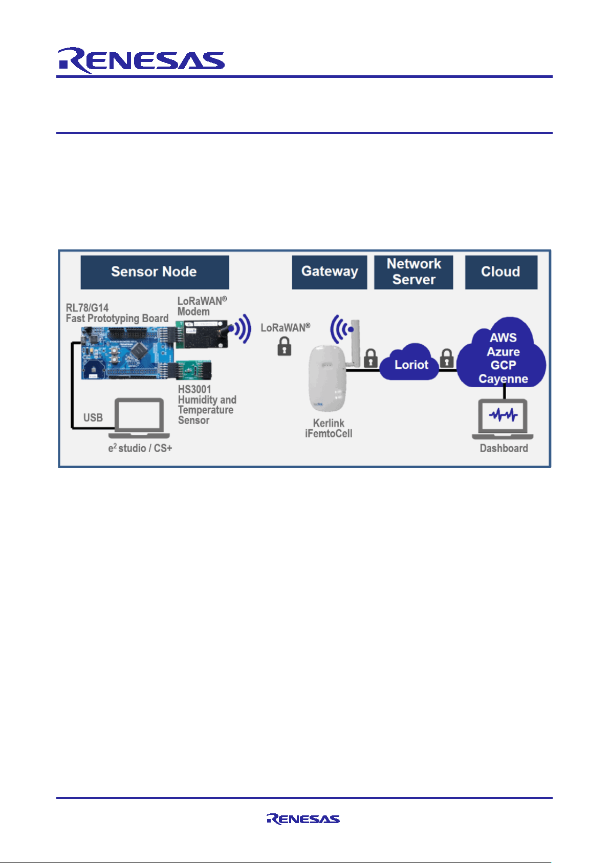
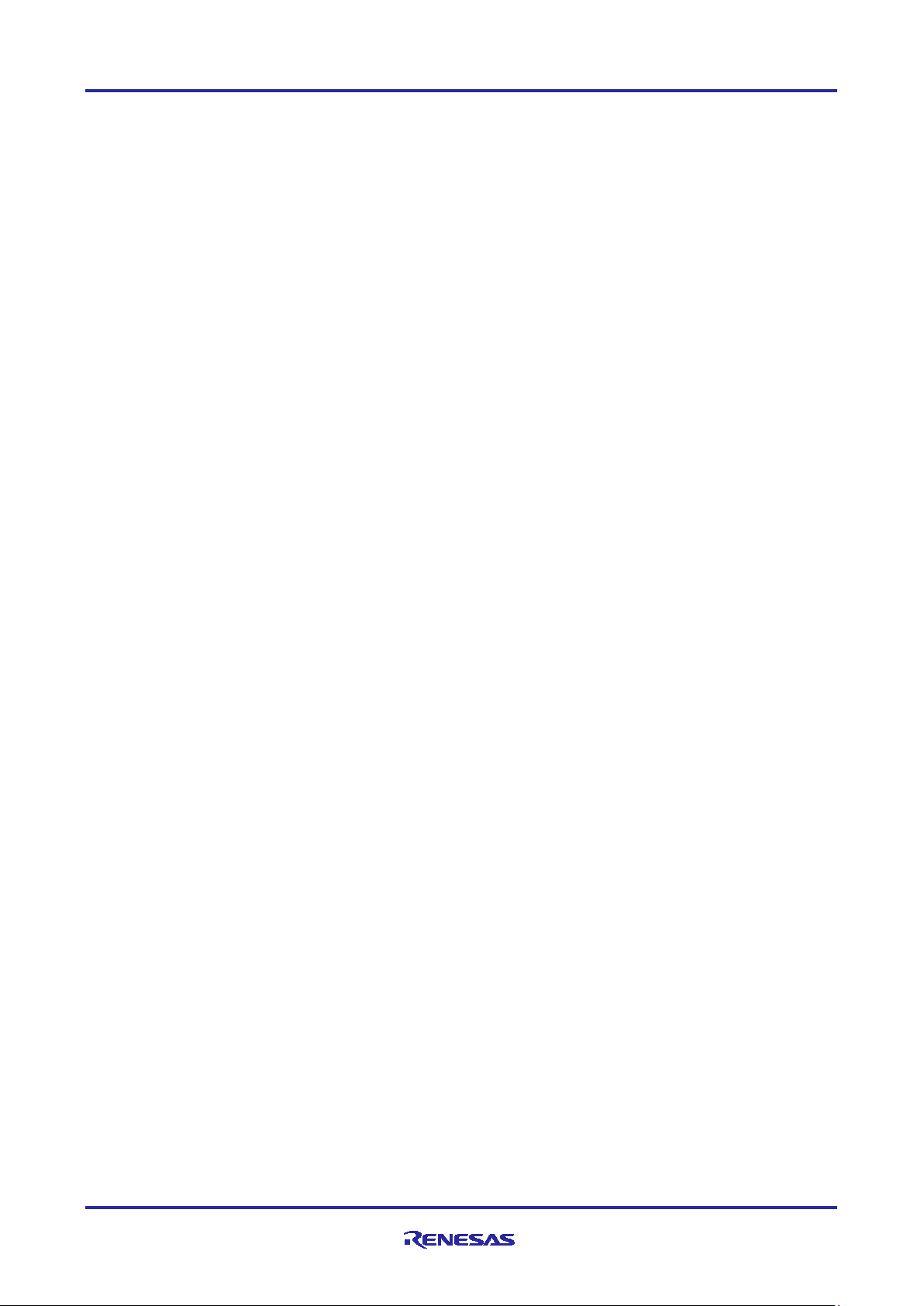
1.1 Demo Overview
Azure
GCP
Humidity and
Temperature
Sensor
iFemtoCell
IoT demo firmware running on RL78/G14 sends the sensor data to the LoRa modem periodically. The LoRa
modem transmits the sensor data with LoRaWAN. The LoRaWAN Gateway (Kerlink iFemtocell) forwards the
received LoRaWAN packets to the LoRaWAN Network Server (Loriot). The Loriot publishes the sensor data
to the Cloud server (AWS/Azure/Cayenne).
In case of Cayenne, the sensor data received Loriot network server is directly forwarded to the Cayenne
because the demo sensor data format is based on the Cayenne LPP (Low Power Payload) 2.0.
In case of Azure, the sensor data (Cayenne LPP format) received by Azure IoT Hub is converted to the
JSON by the demo Function App (C# scripts). To analyze and visualize the sensor data, demo Function App
sends the sensor data to the Azure Time Series Insight Gen2 via Azure Event Hub.
In case of AWS, the sensor data (Cayenne LPP format) received by AWS IoT Core is converted to the JSON
by the domo Lambda Function (Python scripts). The demo Lambda Function stores the senor data to the
Amazon Timestream database. You can visualize the sensor data accessing the timestream database with
Amazon QuickSight or Grafana.
In case of GCP (Google Cloud Platform), the sensor data (Cayenne LPP format) received by Cloud IoT Core
is automatically stored in the Pub/Sub. The domo Cloud Function (Node.js scripts) gets the sensor data from
Pub/Sub and sends the decoded sensor data to the BigQuery. You can visualize the sensor data accessing
the BigQuery with Data Studio (Google Data Portal).
R11AN0412EJ0220 Rev.2.20 Page 3 of 27
Jan 22, 2021
Page 4
LoRaWAN® IoT Demo LPWA IoT Solution with Cloud
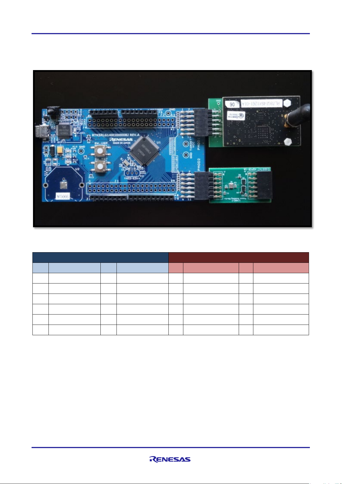
PMOD2 (for Sesnsor)
PMOD1 (for LoRaWAN Modem)
Pin
Function
Pin
Function
Pin
Function
Pin
Function
1
N.C
7
N.C
1
N.C.
7
N.C.
2
N.C.
8
N.C
2
TXD (UART)
8
RESETB
3
SCL (I2C)
9
N.C
3
RXD (UART)
9
N.C.
4
SDA (I2C)
10
N.C
4
N.C.
10
N.C.
5
GND
11
GND
5
GND
11
GND
6
VCC (3.3V)
12
VCC (3.3V)
6
VCC (3.3V)
12
VCC (3.3V)
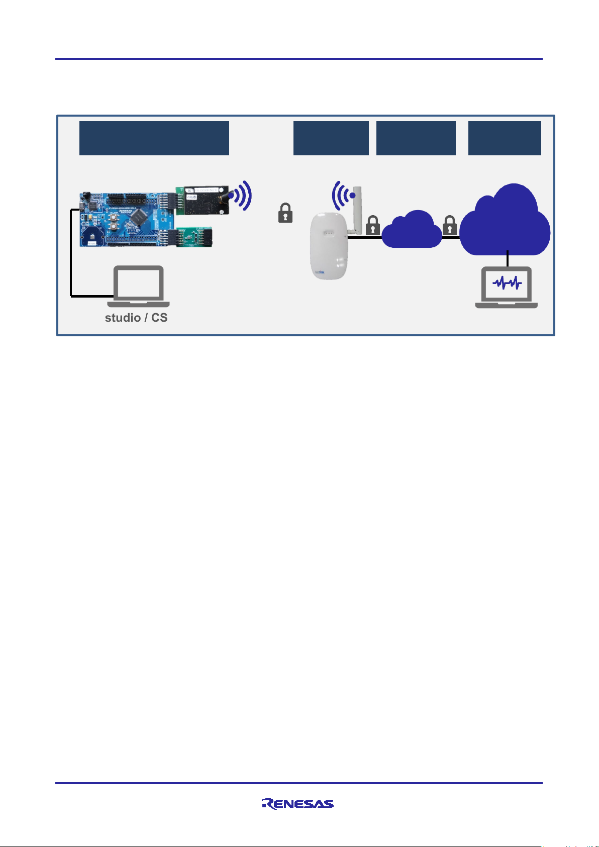
RL78/G14 Fast Prototyping Board
LoRaWAN Modem
on MB-RL1261-06
HS3001 Humidity and
Temperature Sensor
PMOD2
PMOD1
1.2 How to setup the Boards
IoT Demo Board consists of RL78/G14 Fast Prototyping Board, Sensors and LoRa Modem as follows.
PMOD2 and PMOD1 interface configurations.
NOTE1: UART interface is 8bit Non-parity 1stop-bit at 115200bps.
NOTE2: LoRaWAN Modem software on MB-RL1261-06 is based on the LoRaWAN Sample Software
released in “LoRa®-based Wireless Software Package (V2.20)” and ported for the MB-RL1261-06 module.
However, this software is not included in the release package. Please contact the Renesas, if you need.
You can use another RL78/G14 Fast Prototyping Board with SX126x shield instead of the MB-RL1261-06.
NOTE3: The use of wireless receivers and transmitters is restricted by international standards and domestic
regulations. Wireless receivers and transmitters must therefore be used in accordance with the applicable
laws and regulations of the country in which they are being used.
R11AN0412EJ0220 Rev.2.20 Page 4 of 27
Jan 22, 2021
Page 5
LoRaWAN® IoT Demo LPWA IoT Solution with Cloud
1.3 How to setup the Demo Firmware
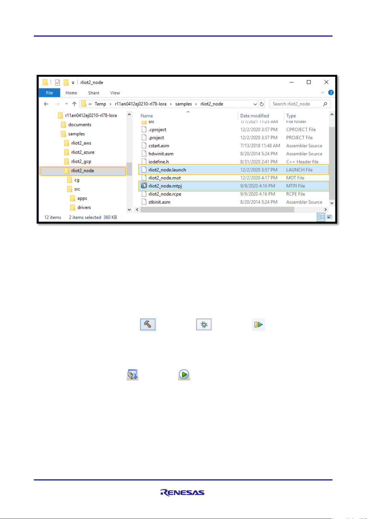
Demo firmware located following directory is designed for the RL78/G14 Fast Prototyping Board.
How to use Demo firmware.
STEP1: Connect the RL78/G14 Fast Prototyping Board with USB cable.
STEP2: Copy the demo firmware folder named “rilot2_node” to a temporary directory (e.g. c\Temp).
2
STEP3: Build and run the demo firmware using IDE(e
studio or CS+).
2
studio ]
[ e
File > Import... > select “Existing Projects into Workspace” > Browse... > select “c:\Temp\rliot2_node”.
After importing the project folder, click button > click button > click button twice.
[ CS+ ]
Open or double click the project file located “c:\Temp\rliot2_node\rliot2_node.mtpj”
After loading the project file, click button > click button.
[ Renesas Flash Programmer (V3.05 or later) ]
File > New Project … > Fill in all field as below > Click “Connect”
Microcontroller : RL78, Project Name and Folder : any , Tool : E2 emulator Lite, Wide Voltage : Not check
Click “Browse” and select “c:\Temp\rliot2_node\rliot2_node.mot” as Program File > Click “Start”
R11AN0412EJ0220 Rev.2.20 Page 5 of 27
Jan 22, 2021
Page 6
LoRaWAN® IoT Demo LPWA IoT Solution with Cloud
Field
Description
Byte
Type
Unit
Remark
CH01
Channel 01 as humidity
2
UInt16
n/a
Fixed
HUMI
Current humidity value
1
UInt8
0.5%
0x5D(93) * 0.5 = 46.5 [%]
CH02
Channel 02 as temperature
2
UInt16
n/a
Fixed
TEMP
Current temperature value
2
Int16
0.1°C
0x00F9(249) * 0.1 = 24.9 [°C]
AT+SENDHEX=”01685D026700F9”
CH01 HUMI CH02 TEMP
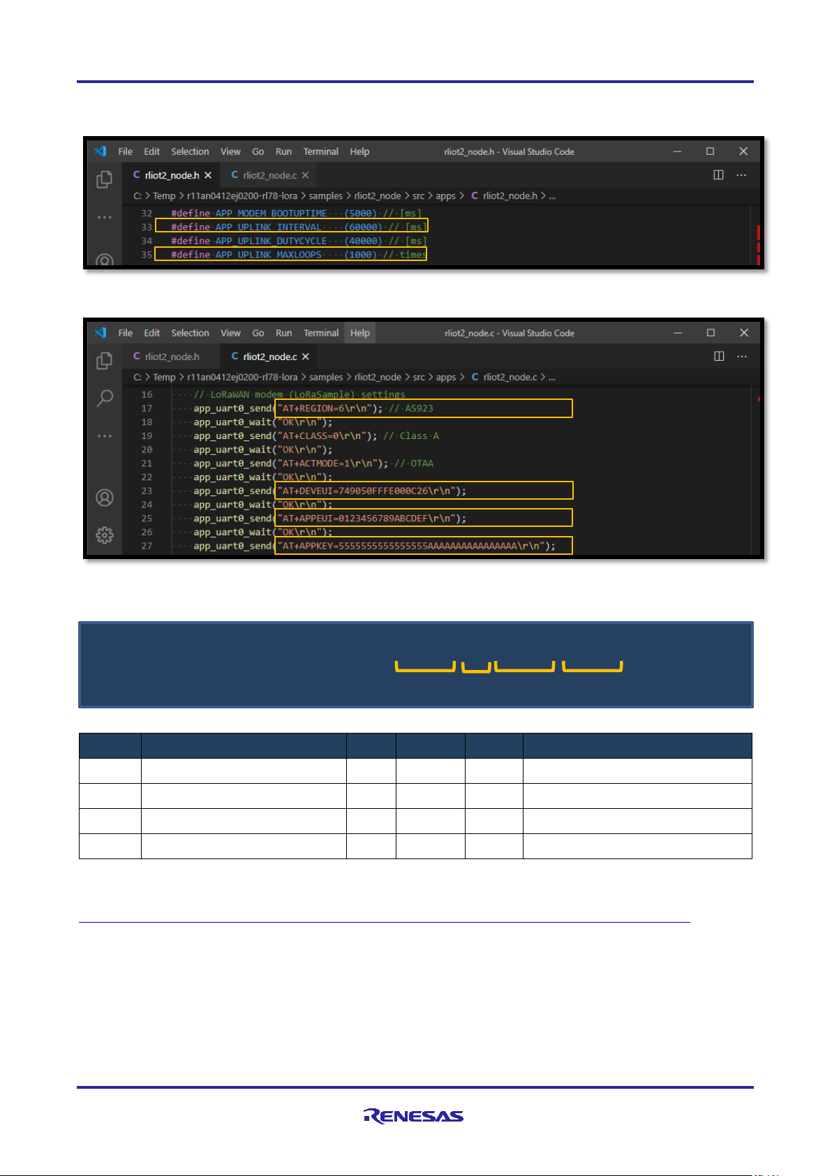
By default, demo firmware will send sensor data, 1000 times at 60000 [ms] intervals. These parameters can
be changed to modify following macro definition described in “src\apps\rliot2_node.h”.
LoRaWAN device configuration (Region, DevEUI, Keys) can be changed in the “src\apps\rliot2_node.c”.
Demo firmware will send a sensor data with following Cayenne LPP format using AT-Command.
NOTE1: Cayenne will recognize any payload based on the Cayenne LPP format. The demo function on the
AWS and Azure support only above format, but you can extend the format by editing the demo functions.
For more detail on the Cayenne LPP 2.0 format, please refer to below.
https://developers.mydevices.com/cayenne/docs/lora/#lora-cayenne-low-power-payload-data-types
NOTE2: The HS300x driver in the demo firmware supports HS3001, HS3002, HS3003 and HS3004.
R11AN0412EJ0220 Rev.2.20 Page 6 of 27
Jan 22, 2021
Page 7

LoRaWAN® IoT Demo LPWA IoT Solution with Cloud
2. LoRaWAN Gateway
2.1 How to setup Kerlink LoRaWAN Gateway
This IoT demo uses Kerlink iFemtoCell as LoRaWAN Gateway and also uses Loriot as LoRaWAN Network
Server. LoRaWAN Gateway is tightly coupled with LoRaWAN Network Server using the Network Server
specific LoRaWAN Packet Forwarder. This means you should install the Loriot specific LoRaWAN Packet
Forwarder into the Kerlink iFemtoCell LoRaWAN Gateway.
Step1. Get Login Account for Kerlink Website (https://www.kerlink.com/
Step2. Get Installation Manual for iFemtocell from Kerlink Website.
Step3. Turn on the Kerlink iFemtoCell.
Step4. (optional) Update Kerlink firmware.
Stpe5. Get Login Account for Loriot Website (https://www.loriot.io/
Step6. Get setup guide for Kerlink iFemtoCell.
Step7. Download the Loriot software package (included Packet Forwarder).
Step8. Install and run the Loriot software package on the Kerlink iFemtoCell.
).
).
R11AN0412EJ0220 Rev.2.20 Page 7 of 27
Jan 22, 2021
Page 8

LoRaWAN® IoT Demo LPWA IoT Solution with Cloud
3. LoRaWAN Network Server
3.1 How to setup the Loriot LoRaWAN Network Server
Loriot provides LoRaWAN Network Server. You should register the LoRaWAN Gateway and LoRaWAN
Devices on the Network Server. You can register the cloud server as the output of the Network Server.
[ Register LoRaWAN Gateway ]
Step1. Login Loriot LoRaWAN Network Server for your region (https://www.loriot.io/login.html
Step2. Go your Loriot Dashboard.
Step3. Click “Networks” > Click “New Network“ > Fill in “Name” field > Click “Create new network”.
Step4. Click “+Add Gateway” > Click “Kerlink iFemtoCell” > Set MAC Address and Location.
Step5. Click “Configure” > Select “Channel Plan” > select Plan (e.g. “AS923” in Japan)
[ Register LoRaWAN Device ]
Step1. Login Loriot LoRaWAN Network Server for your region (https://www.loriot.io/login.html
Step2. Go your Loriot Dashboard.
Step3. Click “APPLICATIONS” > Click “New Application” > Fill in “Name” field.
Step4. Enable “OTTA” on “Features” section
Step5. Click “+Enroll Device” > Select “LoRaWAN 1.0.x” and “OTAA”
Step6. Fill in the “Title”, “Device EUI”, “Application EUI”, “Application Key” > Click “Enroll”
Device EUI is the same as the MAC address labeled on your LoRa Module.
Example settings (Do not use this as your actual settings).
“Device EUI” is 749050FFFE000C26
“Application EUI” is 0123456789ABCDEF
)
)
“Application Key” is 5555555555555555AAAAAAAAAAAAAAAA
R11AN0412EJ0220 Rev.2.20 Page 8 of 27
Jan 22, 2021
Page 9
LoRaWAN® IoT Demo LPWA IoT Solution with Cloud
[ Register the Cloud ]
Step1. Login Loriot LoRaWAN Network Server for your region (https://www.loriot.io/login.html
Step2. Go your Loriot Dashboard > Click “Applications” > Click “APPLICATIONS”
Step3. Click app name (e.g. “Sample App”) > Click “Output” > Click “Add new output” > Select Cloud
Step4. Enter your cloud credential information follow the instructions on the screen.
[ Cayenne ]
No need to enter your credential information regarding Cayenne.
[ AWS IoT ]
Endpoint Random, Region : You can find in AWS > AWS IoT > Settings > Custom Endpoint
Access ID, Key : You can find in AWS > IAM > Users > “loriot” > security credentials
[ Azure IoT ]
“IoT Hub Name” : your Azure IoT Hub name (e.g. “demoIotHubRliot”)
“Primary Key” : Azure > your IoT Hub (e.g. “demoIotHubRliot”) > “Settings” > “Shard access policies” >
“device” > “Shard access key” > “Primary Key”
)
[ GCP IoT ]
Project ID : your GCP project ID (Not project Name) (e.g. “demorliot1”)
Registry ID : your GCP registry ID (e.g. “demoRegistry”)
Region : your GCP region (e.g. “asia-east1”)
Private key : contents of the following ec_private.pem file generated by the openssl command.
openssl ecparam -genkey -name prime256v1 -noout -out ec_private.pem
openssl ec -in ec_private.pem -pubout -out ec_public.pem
R11AN0412EJ0220 Rev.2.20 Page 9 of 27
Jan 22, 2021
Page 10

LoRaWAN® IoT Demo LPWA IoT Solution with Cloud
4. Cayenne Cloud Server
4.1 How to setup Cayenne Cloud Server
Step 1. Create Account on Cayenne (https://developers.mydevices.com/cayenne/lora/)
Step 2. Select “LoRa” > Select “Loriot” as Network > Select “Cayenne LPP” as device > Enter Settings.
DevEUI : your device DevEUI (e.g. 749050FFFE000C26)
Activation Mode : Select “Already Registered”
Loriot Server : Select you loriot server (e.g. “ap2.loriot.io (Asia-Pacific Tokyo, Japan)”)
Loriot App ID : You can find Loriot > APPLICATIONS > SampleApp > Application ID
Loriot Token: You can find Loriot > APPLICATIONS > SampleApp > Access Tokens > Authentication Tokens
Tracking : Select “This device doesn’t move”, Enter Address (e.g. “Tokyo, Japan”)
Click “Add device”
After that, you can see following dashboard.
R11AN0412EJ0220 Rev.2.20 Page 10 of 27
Jan 22, 2021
Page 11

LoRaWAN® IoT Demo LPWA IoT Solution with Cloud
Azure IoT Hub
Function App
Time Series Insight
MQTT
JSON
Event Hub
5. Azure Cloud Server
5.1 How to setup Azure Cloud Server
Azure IoT Hub is MQTT message broker. When you configure the Azure IoT Hub to subscribe the MQTT
messages published by LoRaWAN Network Server, the JSON message including sensor data on MQTT
payload will be routed to the built-in endpoint (IoT Event Hub) which will invoke the demo Function App.
The demo Function App will decode the messages and convert the sensor data from the hex-ascii formatted
as Cayenne LPP (e.g. “01685D026700F9”) to the JSON (e.g. {‘humidity’:46, ‘temperature’:24.9}).
To analyze and visualize the sensor data, the demo Function App will send the sensor data to the Azure
Time Series Insight Gen2 via Azure Event Hub.
Overview:
Step1. Create an instance of the Azure IoT Hub. Register your sensor node as IoT device.
Step2. Create an instance of the Azure Event Hub as event source of the Azure Time Series Insight Gen2.
Step3. Create the demo Function App. Bind the Event Hub as the output of the demoFunction.
Step4. Create the environment of the Azure Time Series Insight Gen2 and connect to the Event Hub.
Step5. Analyze and visualize the sensor data with TSI(Time Series Insight) Explorer.
R11AN0412EJ0220 Rev.2.20 Page 11 of 27
Jan 22, 2021
Page 12

LoRaWAN® IoT Demo LPWA IoT Solution with Cloud
5.2 How to setup Azure IoT Hub and Event Hub
[ Configure Azure IoT Hub ]
Step1. Get Login Account for Azure (https://azure.microsoft.com/free/
Step2. Go your Azure Portal.
Step3. Click “All Services” > Click “Internet of things“ > Click “IoT Hub” > Click “+Add” > Fill in all field.
In this demo, following parameters are used as example (Do not use this as your actual settings).
“Subscription” : “Pay-per-use”
“Resource Group” : “demoResouceGroup” (Create New) Required to create new storage account)
“Region” : “Japan East”
“IoT Hub Name” : “demoIotHubRliot”
“Connectivity Method” : “Public endpoint (all networks)”
“Pricing and scale tier” : “F1 : Free tier” ( max 8000 messages per day)
Step4. Click “IoT devices” > Click “+New” > Fill in “Device ID” as Device EUI > Click “Save”
In this demo, following parameters are used as example (Do not use this as your actual settings).
“Device ID” : 749050FFFE000C26
“Authentication type” : “Symmetric key”
“Primary key” : empty (generated automatically)
“Secondary key” : empty (generated automatically)
“Auto-generate keys” : Checked
)
“Connect this device to an IoT hub” : “Enable”
“Parent device” : none.
[ Configure Azure Event Hub ]
Step1. Get Login Account for Azure (https://azure.microsoft.com/free/
Step2. Go your Azure Portal.
Step3. Click “All Services” > Click “Internet of things“ > Click “Event Hubs” > Click “+Add” > Fill in all field.
In this demo, following parameters are used as example (Do not use this as your actual settings).
“Subscription” : Pay-per-use
“Resource Group” : “demoResourceGroup”
“Namespace name” : “demoEventHubRliot”
“Location” : Japan East
“Pricing tier” : Basic
“Throughput Units” : 1
Click “Create” > Click name (e.g. “demoEventHubRliot”) > Click “+Event Hub” > Fill in all field.
In this demo, following parameters are used as example (Do not use this as your actual settings).
“Name” :”demoTsiEventHub”
)
“Partition Count” :2
Click “Create”
R11AN0412EJ0220 Rev.2.20 Page 12 of 27
Jan 22, 2021
Page 13

LoRaWAN® IoT Demo LPWA IoT Solution with Cloud
5.3 How to setup Azure Function App (Demo Application)
[ Configure Azure Function App ]
Step1. Login Azure
Step2. Go your Azure Portal.
Step3. Click “All services” > “Compute” > “Function App” > Click “+Add“ > Fill in all field > Click “Create”
In this demo, following parameters are used as example (Do not use this as your actual settings).
“Subscription” : “Pay-per-use”
“Resource Group” : Select “demoResourceGroup”
“Function App name” : “demoFunctionRliot”
“Publish” : “Code”
“Runtime stack” : “.Net Core”
“Version” : 3.1
“Location” : “Japan East”
“Storage account” : “demofunctionrliotsa” (create new)
“Operating System” : “Windows”
“Plan type” : “Consumption (Serverless)”
“Enable Application Insights” : Yes
“Application Insights” : “demoFunctionRliot (Japan East)”
Step4. Click app name (e.g. “demoFunctionRliot”) > Click “Start” if the Function app is stopped.
Click “Functions” > Click “+ Add” > Fill in all field > Click “Add”.
In this demo, following parameters are used as example (Do not use this as your actual settings).
“Development environment” : Select “Develop in portal”
“Template” : Select “IoT Hub (Event Hub)”
“Name” : “IoTHub_EventHub1” (Default)
“Event Hub connection” : Click “New” > Select “IoT Hub” > Fill all filed as below > Click “OK”
“demoIotHubRliot” as “Event Hub connection”, “Events (built-in)” as “Event Hub connection”
“Event Hub consumer group” : “$Default”
Step5. Click function name (e.g. “IoTHub_EventHub1”) > Click “Code+Test”
Copy-Paste the C# Script referring “(package top)\samples\rliot2_azure\run.csx” > Click “Save”
Step6. Click “Integration” > Click “+Add output” > Fill in all filed as follow > Click “OK”
In this demo, following parameters are used as example (Do not use this as your actual settings).
“Binding Type” : Select “Azure Event Hubs”
“Event parameter name” : “outputEventHubMessage” (It’s depended on the run.csx)
“Event Hub connection” : Click “New” > Select “Event Hub” > Select as follow > Click “OK”
st
1
“Event Hub Name” : “demotsieventhub”
Step8. Click “Functions” > Click function name (e.g. “IoTHub_EventHub1”) > Click “Enable”
R11AN0412EJ0220 Rev.2.20 Page 13 of 27
Jan 22, 2021
: “demoEventHubRliot”, 2nd: “demotsieventhub”, 3rd: “RootManagesSharedAccessKey”
Page 14

LoRaWAN® IoT Demo LPWA IoT Solution with Cloud
5.4 How to setup Azure Time Series Insight Gen2
[ Configure Azure Time Series Insight Gen2]
Step1. Login Azure
Step2. Go your Azure Portal.
Step3. Click “All services” > “Internet of things” > “Time Series Insight Environments” > Click “+Add“ >
Fill in all field as follow > Click “Create”
In this demo, following parameters are used as example (Do not use this as your actual settings).
“Subscription” : “Pay-per-use”
“Resource Group” : Click “New “ > Enter “demoTsiResourceGroup”
“Environment name” : “demoTsiEnvironment”
“Location” : “West US 2”
“Tier” : “Gen2 (L1)”
“Property name” : “deveui”
“Storage account name” : “demotsirliotsa”
“Storage account kind” : “StorageV2 (general purpose v2)”
“Storage account replication” : “Locally redundant storage (LRS)”
“Hierarchical namespace” : Select “Disabled”
“Enable warm store” : Yes
“Data retention time (in days)” : 7
“Create an event source” : Yes
“Source type” : Select “Event Hub”
“Name” : “demoTsiEventSource”
“Subscription” : Pay-per-use
“Event Hub namespace” : Select “demoEventHubRliot”
“Event Hub name” : Select “demotsieventhub”
“Event Hub access policy name” : Select “RootManageSharedAccessKey”
“Event Hub consumer group” : Select “$Default”
“Property name” : “time”
Click “Review + Create” > After creating, click “Go to resource”
IMPORTANT:
Once you create the Azure Time Series Insights environment, you will continue to be billed until you clean up
the resources regarding the Azure Time Series Insights.
To clean up the resources regarding Azure Time Series Insight Gen2:
Click “Resource groups” icon on portal menu > Click the resource group (e.g. “demoTsiResourceGroup”)
Click “Delete resource group” on top menu > Enter resource group name > Click “Delete”
You should also clean up “demoResourceGroup” when you no longer need to use the IoT Hub ,Function App
and Event Hub.
R11AN0412EJ0220 Rev.2.20 Page 14 of 27
Jan 22, 2021
Page 15
LoRaWAN® IoT Demo LPWA IoT Solution with Cloud
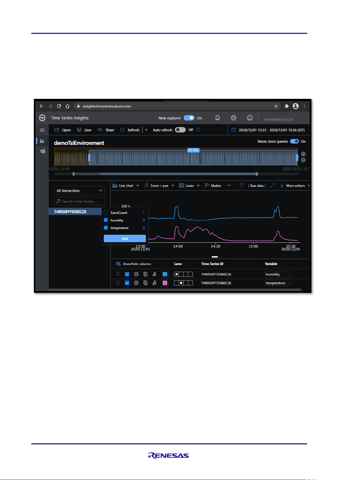
[ Configure TSI Explorer]
Step1. Start sending your sensor node and wait about 3 minutes until the first data is stored to the database.
Step2. Click “TSI Explorer” on top menu > Click “Analyze” Icon on left menu bar.
Step3. Click your DevEUI in the “All hierarchies” > Select “temperature” and “humidity” > Click “Add”
NOTE: If you do not see the DevEUI, click “Refresh” or restart TSI Explorer.
You can create custom type and hierarchies to attach the instance (Time Series ID : DevEUI)
For example, you can change variable names and instance name with following steps.
Step1. Click “Model” Icon on left menu bar
Step2. Click “Types” > Click “+Add type” > Fill in fields as follow > Click “Save”
Name : new type name (e.g. “HS3001”)
Add variable : Name : “Temp”, Kind : “Numeric”, Value : Custom : $event[‘temperature’].Double
Add variable : Name : “Humi”, Kind : “Numeric”, Value : Custom : $event[‘humidity’].Double
Step3. Click “Instances” > Click DevEUI (e.g. 749050FFFE000C26) > Click pencil (edit) icon
> Type : new type name (e.g. “HS3001”)
> Name : new name (e.g. “Sensor1”)
> Click “Save”
R11AN0412EJ0220 Rev.2.20 Page 15 of 27
Jan 22, 2021
Page 16

LoRaWAN® IoT Demo LPWA IoT Solution with Cloud
AWS Cloud
AWS IoT Core
Lambda
Timestream
MQTT
JSON
QuickSight
6. AWS Cloud Server
6.1 How to setup AWS Cloud Server
AWS IoT Core is MQTT message broker. When you configure the AWS IoT Core to subscribe the MQTT
messages published by Loriot LoRaWAN Network Server, the JSON message including sensor data on
MQTT payload will be routed to the demo application (Lambda).
Demo Application will decode the individual sensor value as JSON (e.g. {‘humidity’:46, ‘temperature’:24.9})
from the hex-ascii data stream formatted as Cayenne LPP (e.g. “01685D026700F9”). The demo application
stores sensor data and associated meta information (e.g., DevEUI) in real time to Amazon Timestream.
rd
You can visualize the sensor data with the Amazon QuickSight or 3
party tools (e.g. Grafana).
[ Configuration Steps and References Documents]
Step1. Get Login Account for AWS (https://aws.amazon.com/
Step2. Setup AWS IoT Core (https://docs.aws.amazon.com/iot/latest/developerguide/iot-gs.html)
Step3. Setup Lambda (https://docs.aws.amazon.com/timestream/latest/developerguide/Lambda.html)
Step4. Setup Timestream (https://docs.aws.amazon.com/timestream/index.html)
Step5. Setup QuickSight(https://docs.aws.amazon.com/timestream/latest/developerguide/Quicksight.html)
or Setup Grafana (https://docs.aws.amazon.com/timestream/latest/developerguide/Grafana.html)
NOTE:
All resources (things endpoint on the AWS IoT Core, AWS Lambda function, Amazon Timestream
databases/tables, and Amazon QuickSight dataset) should be created in the same region.
Amazon Timestream is available in US East (N.Virginia), US East (Ohio), Europe(Ireland), and US West
(Oregon) at this time (Jan 21, 2021). If you use the Amazon QuickSight with Amazon Timestream, we
recommend using the US East (N.Virginia) region.
INFORMATION:
AWS IoT Core for LoRaWAN has been released in December 2020 but is not covered in this document.
)
R11AN0412EJ0220 Rev.2.20 Page 16 of 27
Jan 22, 2021
Page 17

LoRaWAN® IoT Demo LPWA IoT Solution with Cloud
6.2 How to setup AWS IoT Core
Step1. Login AWS > Select “IoT Core” from services menu.
Step2. Click Secure > Policies > Create, and fill out the fields as follows, and then save the policy.
Policy name : “demoPolicy”
Policy document: click “Advanced” > Enter the following policy description for demo use only.
NOTE: This policy allows full access to the IoT Core, so do not use it for production use.
Step3. Click Manage > Things > Create, and fill out the fields as follows, and then save the things.
Thing Name: DevEUI of your device (e.g. “749050FFFE000C26”)
Thing Type: “No type selected” ( If you need a thing type, you can create it)
After that, you can generate, download and activate the certification files.
Select “demoPolicy” as a policy to attach to this certificate.
Step4. Click Act > Rules > Create, and fill out the fields as follows, and the save the rule.
Rule Name: “demoRule”
Rule query statement (SQL version 2016-03-23):
NOTE: This query statement is for the Loriot network server only, because the MQTT topic and contents are
network server specific. Loriot send the message on the ‘$aws/things/DevEUI/shadow/update/documents’ as
topic and LoRaWAN uplink packet is located in the current.state.reported when ‘cmd’ is “rx”.
Step5. Click “Add Action” on Act.Rules > Select “Send a message to Lambda function” (Not “Timestream”) >
Click “Configure action” > Click “New Lambda function”. After creating the Lambda function, you should
select “demoFunction” as Lambda function associated with this rule > Click “Add action” > Click “Add Rule”
R11AN0412EJ0220 Rev.2.20 Page 17 of 27
Jan 22, 2021
Page 18

LoRaWAN® IoT Demo LPWA IoT Solution with Cloud
6.3 How to setup AWS Lambda (Demo Application)
To use the Amazon Timestream from Lambda (Python), Python SDK(boto3) v1.15.9 or later is required.
However, current default boto3 supported in AWS Lambda is older than v1.15.9. As a workaround to this,
you should upload the latest boto3 as a Lambda Layer.
Step1. Previous section Step5 Click “New Lambda function” or Select “Lambda” from services menu > Click
Functions > “Create function” > Select “Author from scratch”
Function name : “demoFunction”
Runtime : Python 3.8
Click “Create function”
Step2. Click Functions > “demoFunction” > Click “Actions” on Function code > Select “Upload a .zip file”
Upload the demoFunction.zip located in the release package\samples\rliot2_aws\demoFunction.zip
Click “Edit” on “Runtime Settings” > Set “lambda_function.lambda_handler” as hander > Click “Save”
Step3. Attach the timestream access permission to the AWS Lambada function by following steps.
Click “Permissions” Tab on top.
Click Role name (e.g. “demoFunction-role-jjagv5pu”) on “Execution role” card.
Click “Attach policies” > Search “AmazonTimestreamFullAccess”.
Click check box on “AmazonTimestreamFullAccess” > Click “Attach Policy” for demo use only.
NOTE: This policy allows full access to the Amazon Timestream, so do not use it for production use.
INFORMATION:
Now, the latest Lambda runtime for Python 3.8 (Boto3 V1.15.16) supports Amazon Timestream API. No
need to add the latest Boto3 as Lambda Layer.
R11AN0412EJ0220 Rev.2.20 Page 18 of 27
Jan 22, 2021
Page 19

LoRaWAN® IoT Demo LPWA IoT Solution with Cloud
6.4 How to setup Amazon Timestream
Step1. Select “Amazon Timestream” from services menu > Click Databases > Click “Create database”
Configuration: “Standard database”
Database Name : “demoDatabase”
Encryption Master Key : empty (After creating database, “aws/timestream” will be set).
Click “Create database”
Step2. Click Tables > Click “Create table”
Database Name : “demoDatabase”
Table Name : “demoTable”
Memory store retention : 2 hours
Magnetic store retention : 1 day
Click “Create table”
NOTE: If you change the Database Name and Table Name, you should change the lambda_function.py.
Step3. Click “Query editor” > Click “- - -” and Select “Preview data” > Click “Run”
IMPORTANT:
You will continue to be billed until you stop the services and delete the resources you have created.
R11AN0412EJ0220 Rev.2.20 Page 19 of 27
Jan 22, 2021
Page 20

LoRaWAN® IoT Demo LPWA IoT Solution with Cloud
6.5 How to setup Amazon QuickSight
Step1. Login AWS > Select “QuickSight” from services menu.
Step2. Sign in the QuickSight (You need to select the same region as Timestream (e.g. US East (Virginia))
Step3. Click “Datasets” > Click “New dataset” > Select “Timestream” card
Step4. Enter “demoDatabase” as Data source name > Click “Validate connection” > Click “Create data
source” > Select “demoTable” > Click “Select” > Select “Directly query your data” > Click “Visualize”
Step5. Visualize Humidity and Temperature by following steps.
Select “Line Chart” on visual styles menu.
Click “time” (on “Fields list”)
Click “measure_value” (on “Fields list)
Click “measure_name” (on “Fields list)
Click “time” (on “Field wells”) > Select “Minute” as aggregate.
Click “Themes” (on Left Menu”) > Select “Midnight” > Click “…” > Click “Apply”
Finally, you can see the following charts.
IMPORTANT:
You will continue to be billed until you unsubscribe from Amazon QuickSight.
To unsubscribe from Amazon QuickSight, Click your name on top bar > Select “Manage QuickSight” > Click
“Account settings” > Click “Unsubscribe”.
R11AN0412EJ0220 Rev.2.20 Page 20 of 27
Jan 22, 2021
Page 21

LoRaWAN® IoT Demo LPWA IoT Solution with Cloud
6.6 How to setup Grafana
Step1. Install Grafana (https://grafana.com/) on your PC or Get Login Grafana Cloud.
Step2. Install plugin for Timestream (https://grafana.com/grafana/plugins/grafana-timestream-datasource)
Click Gear mark > Click “Data Sources” > Click “Add data source” > Select Amazon Timestream.
Auth Provider : Access & secret key
Access Key ID : Your AWS Access Key (AWS > IAM > Users > Security Credentials > Create Access Key)
Secret Key : Your AWS Secret Key (AWS > IAM > Users > Security Credentials > Create Access Key)
Default Region : us-east-1
(following default query macros settings are optional.)
Default Query Macros: $__database:demoDatabase, $__table:demoTable, $__measure:temperature
Step3.Click “+” mark (Add Dashboard) > Click “Add New Panel” > Set query commands (SQL) like as below.
Finally, you can see the temperature and humidity data on the dashboard.
INFORMATION:
Amazon Managed Service for Grafana has been released in 2020/12, but is not covered in this document.
R11AN0412EJ0220 Rev.2.20 Page 21 of 27
Jan 22, 2021
Page 22

LoRaWAN® IoT Demo LPWA IoT Solution with Cloud
Cloud IoT Core
Pub/Sub
BigQuery
MQTT
JSON
Cloud Functions
7. GCP Cloud Server
7.1 How to setup GCP Cloud Server
GCP IoT Core is MQTT message broker. When you configure the GCP IoT Core to subscribe the MQTT
messages published by Loriot LoRaWAN Network Server, the JSON message including sensor data on
MQTT payload will be routed to the demo application (Cloud Function) via Pub/Sub.
Demo Application will decode the individual sensor value as JSON (e.g. {‘humidity’:46, ‘temperature’:24.9})
from the hex-ascii data stream formatted as Cayenne LPP (e.g. “01685D026700F9”). The demo application
stores sensor data and associated meta information (e.g., DevEUI) to the BigQuery.
You can visualize the sensor data with the Data Studio (Data Portal).
Overview:
Step1. Create a new project for this demonstration.
Step2. Create a public key and private key for secure connection between Loriot and GCP.
Step3. Create an instance of the Cloud IoT Core and register your sensor node.
Step4. Create an instance of the Pub/Sub as an endpoint of the Cloud IoT Core.
Step5. Create an instance of the GCP Cloud Function as demo application.
Step6. Query and visualize the sensor data with BigQuery and Data Studio (Google Data Portal).
7.2 How to create a new project
Step1. Login GCP > Select “HOME” from services menu
Step2. Click current project name on the top bar (e.g. “My First Project”)
Step3. Click “CREATE PROJECT” and fill in all field as follow > Click “CREATE”
In this demo, following parameters are used as example (Do not use this as your actual settings).
Project Name : “demoRliot1” (Project ID : “demorliot1”)
Location : “No organization” (default)
R11AN0412EJ0220 Rev.2.20 Page 22 of 27
Jan 22, 2021
Page 23

LoRaWAN® IoT Demo LPWA IoT Solution with Cloud
7.3 How to setup GCP Cloud IoT Core
Step1. Login GCP > Select “IoT Core” from services menu > Click “ENABLE”
Step2. Click “CREATE REGISTRY” and fill in all field as follow > Click “CREATE”
In this demo, following parameters are used as example (Do not use this as your actual settings).
Registry ID : “demoRegistry”
Region : asia-east1
Pub/Sub Topic : Click pull down list > Click “CREATE A TOPIC”
Enter Topic ID : “Telemetry” > Click “CREATE TOPIC”
Step3. Click “Devices” > Click “CREATE A DEVICE” > Fill in all field as follow > Click “CREATE”
In this demo, following parameters are used as example (Do not use this as your actual settings).
Device ID : “DEV749050FFFE000C26” ( Format : “DEV” + DevEUI(upper case letters is required) )
Click “COMMUNICATION, CLOUD LOGGING, AUTHENTICATION”
Scroll down to “Authentication (optional)”
Input method : Select “Enter manually”
Public key format : Select “ES256”
Public key value : content of the ec_public.pem file (see section 3. LoRaWAN Network Server)
Public key expiration date (optional) : default
7.4 How to setup GCP Pub/Sub
Step1. Login GCP > Select “Pub/Sub” from services menu.
Step2. Click your topic (e.g. “Telemetry”) in the Topic ID field
Step3. Click “CREATE SUBSCRIPTION” and Select “Create subscription”
Step4. Fill in all field as follow > Click “CREATE”
In this demo, following parameters are used as example (Do not use this as your actual settings).
Subscription ID : “sensor”
Delivery type : Select “Pull”
Message retention duration : 0 Days, 2 Hours, 0 Minutes
Retain acknowledged message : disabled (default)
Subscription expiration : 1 Days
Acknowledgement deadline : 10 Seconds (default)
Subscription filter : none (default)
Message ordering : disabled (default)
Dead lettering : disabled (default)
Retry policy : Select “Retry immediately”
R11AN0412EJ0220 Rev.2.20 Page 23 of 27
Jan 22, 2021
Page 24

LoRaWAN® IoT Demo LPWA IoT Solution with Cloud
7.5 How to setup GCP Cloud Functions
Step1. Login GCP > Select “Cloud Functions” from services menu
Step2. Click “CREATE FUNCTION” and Fill in all field as follow > Click “CREATE”
In this demo, following parameters are used as example (Do not use this as your actual settings).
Function name : “demoFunction”
Region : Select “asia-northeast1”
Trigger type : Select “Cloud Pub/Sub”
Select a Cloud Pub/Sub topic : Select “projects/demorliot1/topics/Telemetry”
Retry on failure : disabled (default)
Click “VARIABLES, NETWORKING AND ADVANCED SETTINGS”
Memory allocated : Select “128 MiB”
Click “SAVE” and Click “NEXT”
Runtime : Select “Node.js 12” > Entry Point : “demoFunction” > Click “Enable API” (first time only)
Source code : Select “Inline Editor”
Click “index.js” > Copy-Paste the contents of the samples\rliot_gcp\index.js file
Click “package.json” > Copy-Paste the contents of the samples\rliot_gcp\package.json
Click “DEPLOY”
7.6 How to setup GCP BigQuery
Step1. Login GCP > Select “BigQuery” from services menu
Step2. Click your project (e.g. “demorliot1”) on side menu (e.g. Resources/demorliot1)
Step3. Click “CREATE DATASET” and Fill in all field as follow > Click “Create dataset”
In this demo, following parameters are used as example (Do not use this as your actual settings).
Dataset ID : “demoDataset”
Default table expiration : Never
Encryption : Select “Google-managed key”
Step4. Click “demoDataset” on side menu (e.g. Resources/demorliot1/demoDataset)
Step5. Click “CREATE TABLE” and Fill in all field as follow > Click “Create table”
In this demo, following parameters are used as example (Do not use this as your actual settings).
Create table from : Select “Empty table”
Destination : Select “Search for a project”
Project Name : “demoRliot1”, Dataset name : “demoDataset”
Table name : “demoTable”
Add following fields as schema
Name : “device_id”, Type : “STRING”, Mode : “NULLABLE”
Name : “time”, Type : “TIMESTAMP”, Mode : “NULLABLE”
Name : “humidity”, Type : “FLOAT”, Mode : “NULLABLE”
Name : “temperature”, Type : “FLOAT”, Mode : “NULLABLE”
R11AN0412EJ0220 Rev.2.20 Page 24 of 27
Jan 22, 2021
Page 25

LoRaWAN® IoT Demo LPWA IoT Solution with Cloud
NOTE: If you change the Dataset name and Table name, you should change the index.js (see below).
Step6. Input following SQL in the Query editor (The FROM clause should be set to the actual path.)
SELECT *
FROM demorliot1.demoDataset.demoTable
ORDER BY time DESC
LIMIT 50
Step7. Start sensor node and wait a few minutes until several sensor data are stored into the data table.
Step8. Click “Run” > Click your data table (e.g. “demoTable”) > You can find the sensor data (see below)
Step9. Click “EXPLORE DATA” > Select “Explore Data Studio”
IMPORTANT:
Once you create the resources (Cloud IoT Core, Pub/Sub, Cloud Functions and BigQuery) on your project,
you will continue to be billed until you clean up the resources or shut down your project.
To shut down your project:
Step1. Click “Home” on menu > Select your project (e.g. “demoRliot1”) > Click “DASHBOARD” tab.
Step2. Click “Go to project settings” on Project info tile
Step3. Click “SHUT DOWN” > Enter your project ID (e.g. “demorliot1”) > Click “SHUT DOWN”
R11AN0412EJ0220 Rev.2.20 Page 25 of 27
Jan 22, 2021
Page 26

LoRaWAN® IoT Demo LPWA IoT Solution with Cloud
7.7 How to setup Data Studio (Google Data Portal)
Step1. Select chart type “Table”
Step2. Click “DATA” tab > Configure data settings
Data Range Dimension : time (Date)
Dimension : time
Metric : humidity
Step3. Select chart type “Time Series”
Step4. Click “STYLE” tab > Configure style settings
Series color : blue
Missing Data : Select “Liner interpolation”
Step5. Click “Add a chart”
Step6. Repeat Step1 to Step4 with Metric : temperature, Series color : orange.
Finally, you can see the following charts.
R11AN0412EJ0220 Rev.2.20 Page 26 of 27
Jan 22, 2021
Page 27

LoRaWAN® IoT Demo LPWA IoT Solution with Cloud
Rev.
Date
Description
Page
Summary
1.00
Oct 04, 2019
All
Initial version (Generation 1)
1.10
Nov 07, 2019
5,10,13
Changed file path regarding firmware and scripts.
2.00
Dec 11, 2020
All
Initial version (Generation 2)
Supports the Azure Time Series Insight Gen2.
2.10
Jan 12, 2021
18
All
Add note regarding lambda_function.py for AWS
Supports the GCP(Google Cloud Platform)
2.20
Jan 22, 2021
18
All
Add note regarding timestream access permission.
Supports the Amazon QuickSight.
Revision History
Generation 2 is NOT compatible with Generation 1.
Supports the Renesas HS300x sensor module.
Supports the Cayenne (myDevices).
Supports the Amazon Timestream for AWS.
18
No need to add latest Boto3 layer for Lambda function.
R11AN0412EJ0220 Rev.2.20 Page 27 of 27
Jan 22, 2021
Page 28

General Precautions in the Handling of Microprocessing Unit and Microcontroller Unit Products
The following usage notes are applicable to all Microprocessing unit and Microcontroller unit products from Renesas. For detailed usage notes on the
products covered by this document, refer to the relevant sections of the document as well as any technical updates that have been issued for the products.
1. Precaution against Electrostatic Discharge (ESD)
A strong electrical field, when exposed to a CMOS device, can cause destruction of the gate oxide and ultimately degrade the device operation. Steps
must be taken to stop the generation of static electricity as much as possible, and quickly dissipate it when it occurs. Environmental control must be
adequate. When it is dry, a humidifier should be used. This is recommended to avoid using insulators that can easily build up static electricity.
Semiconductor devices must be stored and transported in an anti-static container, static shielding bag or conductive material. All test and
measurement tools including work benches and floors must be grounded. The operator must also be grounded using a wrist strap. Semiconductor
devices must not be touched with bare hands. Similar precautions must be taken for printed circuit boards with mounted semiconductor devices.
2. Processing at power-on
The state of the product is undefined at the time when power is supplied. The states of internal circuits in the LSI are indeterminate and the states of
register settings and pins are undefined at the time when power is supplied. In a finished product where the reset signal is applied to the external reset
pin, the states of pins are not guaranteed from the time when power is supplied until the reset process is completed. In a similar way, the states of pins
in a product that is reset by an on-chip power-on reset function are not guaranteed from the time when power is supplied until the power reaches the
level at which resetting is specified.
3. Input of signal during power-off state
Do not input signals or an I/O pull-up power supply while the device is powered off. The current injection that results from input of such a signal or I/O
pull-up power supply may cause malfunction and the abnormal current that passes in the device at this time may cause degradation of internal
elements. Follow the guideline for input signal during power-off state as described in your product documentation.
4. Handling of unused pins
Handle unused pins in accordance with the directions given under handling of unused pins in the manual. The input pins of CMOS products are
generally in the high-impedance state. In operation with an unused pin in the open-circuit state, extra electromagnetic noise is induced in the vicinity of
the LSI, an associated shoot-through current flows internally, and malfunctions occur due to the false recognition of the pin state as an input signal
become possible.
5. Clock signals
After applying a reset, only release the reset line after the operating clock signal becomes stable. When switching the clock signal during program
execution, wait until the target clock signal is stabilized. When the clock signal is generated with an external resonator or from an external oscillator
during a reset, ensure that the reset line is only released after full stabilization of the clock signal. Additionally, when switching to a clock signal
produced with an external resonator or by an external oscillator while program execution is in progress, wait until the target clock signal is stable.
6. Voltage application waveform at input pin
Waveform distortion due to input noise or a reflected wave may cause malfunction. If the input of the CMOS device stays in the area between V
(Max.) and V
input level is fixed, and also in the transition period when the input level passes through the area between V
7. Prohibition of access to reserved addresses
Access to reserved addresses is prohibited. The reserved addresses are provided for possible future expansion of functions. Do not access these
addresses as the correct operation of the LSI is not guaranteed.
8. Differences between products
Before changing from one product to another, for example to a product with a different part number, confirm that the change will not lead to problems.
The characteristics of a microprocessing unit or microcontroller unit products in the same group but having a different part number might differ in terms
of internal memory capacity, layout pattern, and other factors, which can affect the ranges of electrical characteristics, such as characteristic values,
operating margins, immunity to noise, and amount of radiated noise. When changing to a product with a different part number, implement a system-
evaluation test for the given product.
(Min.) due to noise, for example, the device may malfunction. Take care to prevent chattering noise from entering the device when the
IH
(Max.) and VIH (Min.).
IL
IL
Page 29

Corporate Headquarters
Contact information
www.renesas.com
Trademarks
of their respective owners.
Notice
1. Descriptions of circuits, software and other related information in this document are provided only to illustrate the operation of semiconductor products
and application examples. You are fully responsible for the incorporation or any other use of the circuits, software, and information in the design of your
product or system. Renesas Electronics disclaims any and all liability for any losses and damages incurred by you or third parties arising from the use
of these circuits, software, or information.
2. Renesas Electronics hereby expressly disclaims any warranties against and liability for infringement or any other claims involving patents, copyrights,
or other intellectual property rights of third parties, by or arising from the use of Renesas Electronics products or technical information described in this
document, including but not limited to, the product data, drawings, charts, programs, algorithms, and application examples.
3. No license, express, implied or otherwise, is granted hereby under any patents, copyrights or other intellectual property rights of Renesas Electronics
or others.
4. You shall not alter, modify, copy, or reverse engineer any Renesas Electronics product, whether in whole or in part. Renesas Electronics disclaims any
and all liability for any losses or damages incurred by you or third parties arising from such alteration, modification, copying or reverse engineering.
5. Renesas Electronics products are classified according to the following two quality grades: “Standard” and “High Quality”. The intended applications for
each Renesas Electronics product depends on the product’s quality grade, as indicated below.
"Standard": Computers; office equipment; communications equipment; test and measurement equipment; audio and visual equipment; home
"High Quality": Transportation equipment (automobiles, trains, ships, etc.); traffic control (traffic lights); large-scale communication equipment; key
Unless expressly designated as a high reliability product or a product for harsh environments in a Renesas Electronics data sheet or other Renesas
Electronics document, Renesas Electronics products are not intended or authorized for use in products or systems that may pose a direct threat to
human life or bodily injury (artificial life support devices or systems; surgical implantations; etc.), or may cause serious property damage (space
system; undersea repeaters; nuclear power control systems; aircraft control systems; key plant systems; military equipment; etc.). Renesas Electronics
disclaims any and all liability for any damages or losses incurred by you or any third parties arising from the use of any Renesas Electronics product
that is inconsistent with any Renesas Electronics data sheet, user’s manual or other Renesas Electronics document.
6. When using Renesas Electronics products, refer to the latest product information (data sheets, user’s manuals, application notes, “General Notes for
Handling and Using Semiconductor Devices” in the reliability handbook, etc.), and ensure that usage conditions are within the ranges specified by
Renesas Electronics with respect to maximum ratings, operating power supply voltage range, heat dissipation characteristics, installation, etc. Renesas
Electronics disclaims any and all liability for any malfunctions, failure or accident arising out of the use of Renesas Electronics products outside of such
specified ranges.
7. Although Renesas Electronics endeavors to improve the quality and reliability of Renesas Electronics products, semiconductor products have specific
characteristics, such as the occurrence of failure at a certain rate and malfunctions under certain use conditions. Unless designated as a high reliability
product or a product for harsh environments in a Renesas Electronics data sheet or other Renesas Electronics document, Renesas Electronics
products are not subject to radiation resistance design. You are responsible for implementing safety measures to guard against the possibility of bodily
injury, injury or damage caused by fire, and/or danger to the public in the event of a failure or malfunction of Renesas Electronics products, such as
safety design for hardware and software, including but not limited to redundancy, fire control and malfunction prevention, appropriate treatment for
aging degradation or any other appropriate measures. Because the evaluation of microcomputer software alone is very difficult and impractical, you are
responsible for evaluating the safety of the final products or systems manufactured by you.
8. Please contact a Renesas Electronics sales office for details as to environmental matters such as the environmental compatibility of each Renesas
Electronics product. You are responsible for carefully and sufficiently investigating applicable laws and regulations that regulate the inclusion or use of
controlled substances, including without limitation, the EU RoHS Directive, and using Renesas Electronics products in compliance with all these
applicable laws and regulations. Renesas Electronics disclaims any and all liability for damages or losses occurring as a result of your noncompliance
with applicable laws and regulations.
9. Renesas Electronics products and technologies shall not be used for or incorporated into any products or systems whose manufacture, use, or sale is
prohibited under any applicable domestic or foreign laws or regulations. You shall comply with any applicable export control laws and regulations
promulgated and administered by the governments of any countries asserting jurisdiction over the parties or transactions.
10. It is the responsibility of the buyer or distributor of Renesas Electronics products, or any other party who distributes, disposes of, or otherwise sells or
transfers the product to a third party, to notify such third party in advance of the contents and conditions set forth in this document.
11. This document shall not be reprinted, reproduced or duplicated in any form, in whole or in part, without prior written consent of Renesas Electronics.
12. Please contact a Renesas Electronics sales office if you have any questions regarding the information contained in this document or Renesas
Electronics products.
(Note1) “Renesas Electronics” as used in this document means Renesas Electronics Corporation and also includes its directly or indirectly controlled
(Note2) “Renesas Electronics product(s)” means any product developed or manufactured by or for Renesas Electronics.
subsidiaries.
electronic appliances; machine tools; personal electronic equipment; industrial robots; etc.
financial terminal systems; safety control equipment; etc.
(Rev.4.0-1 November 2017)
TOYOSU FORESIA, 3-2-24 Toyosu,
Koto-ku, Tokyo 135-0061, Japan
Semtech, the Semtech logo, LoRa, LoRaWAN and LoRa Alliance are
registered trademarks or service marks, or trademarks or service
marks, of Semtech Corporation and/or its affiliates.
Renesas and the Renesas logo are trademarks of Renesas Electronics
Corporation. All trademarks and registered trademarks are the property
For further information on a product, technology, the most up-to-date
version of a document, or your nearest sales office, please visit:
www.renesas.com/contact/
.
© 2021 Renesas Electronics Corporation. All rights reserved.
 Loading...