

Page 1
All information contained in these materials, including products and product specifications,
represents information on the product at the time of publication and is subject to change by
Renesas Electronics Corp. without notice. Please review the latest information published by
Renesas Electronics Corp. through various means, including the Renesas Electronics Corp.
website (http://www.renesas.com).
Linux Interface
Specification
Yocto recipe Start-Up Guide
User’s Manual: Software
Rev.1.07 Feb. 26, 2021
RZ/G2 group
User
’s Manual
www.renesas.com
Page 2

Corporate Headquarters
Contact information
TOYOSU FORESIA, 3-2-24 Toyosu,
Koto-ku, Tokyo 135-0061, Japan
www.renesas.com
For further information on a product, technology, the most up-to-date
version of a document, or your nearest sales office, please visit:
www.renesas.com/contact/.
Trademarks
Renesas and the Renesas logo are trademarks of Renesas
Electronics Corporation. All trademarks and registered trademarks
are the property of their respective owners.
Notice
1. Descriptions of circuits, software and other related information in this document are provided only to illustrate the operation of semiconductor products
and application examples. You are fully responsible for the incorporation or any other use of the circuits, software, and information in the design of your
product or system. Renesas Electronics disclaims any and all liability for any losses and damages incurred by you or third parties arising from the use of
these circuits, software, or information.
2. Renesas Electronics hereby expressly disclaims any warranties against and liability for infringement or any other claims involving patents, copyrights, or
other intellectual property rights of third parties, by or arising from the use of Renesas Electronics products or technical information described in this
document, including but not limited to, the product data, drawings, charts, programs, algorithms, and application examples.
3. No license, express, implied or otherwise, is granted hereby under any patents, copyrights or other intellectual property rights of Renesas Electronics or
others.
4. You shall not alter, modify, copy, or reverse engineer any Renesas Electronics product, whether in whole or in part. Renesas Electronics disclaims any
and all liability for any losses or damages incurred by you or third parties arising from such alteration, modification, copying or reverse engineering.
5. Renesas Electronics products are classified according to the following two quality grades: “Standard” and “High Quality”. The intended applications for
each Renesas Electronics product depends on the product’s quality grade, as indicated below.
"Standard": Computers; office equipment; communications equipment; test and measurement equipment; audio and visual equipment; home
"High Quality": Transportation equipment (automobiles, trains, ships, etc.); traffic control (traffic lights); large-scale communication equipment; key
Unless expressly designated as a high reliability product or a product for harsh environments in a Renesas Electronics data sheet or other Renesas
Electronics document, Renesas Electronics products are not intended or authorized for use in products or systems that may pose a direct threat to
human life or bodily injury (artificial life support devices or systems; surgical implantations; etc.), or may cause serious property damage (space system;
undersea repeaters; nuclear power control systems; aircraft control systems; key plant systems; military equipment; etc.). Renesas Electronics disclaims
any and all liability for any damages or losses incurred by you or any third parties arising from the use of any Renesas Electronics product that is
inconsistent with any Renesas Electronics data sheet, user’s manual or other Renesas Electronics document.
6. When using Renesas Electronics products, refer to the latest product information (data sheets, user’s manuals, application notes, “General Notes for
Handling and Using Semiconductor Devices” in the reliability handbook, etc.), and ensure that usage conditions are within the ranges specified by
Renesas Electronics with respect to maximum ratings, operating power supply voltage range, heat dissipation characteristics, installation, etc. Renesas
Electronics disclaims any and all liability for any malfunctions, failure or accident arising out of the use of Renesas Electronics products outside of such
specified ranges.
7. Although Renesas Electronics endeavors to improve the quality and reliability of Renesas Electronics products, semiconductor products have specific
characteristics, such as the occurrence of failure at a certain rate and malfunctions under certain use conditions. Unless designated as a high reliability
product or a product for harsh environments in a Renesas Electronics data sheet or other Renesas Electronics document, Renesas Electronics products
are not subject to radiation resistance design. You are responsible for implementing safety measures to guard against the possibility of bodily injury,
injury or damage caused by fire, and/or danger to the public in the event of a failure or malfunction of Renesas Electronics products, such as safety
design for hardware and software, including but not limited to redundancy, fire control and malfunction prevention, appropriate treatment for aging
degradation or any other appropriate measures. Because the evaluation of microcomputer software alone is very difficult and impractical, you are
responsible for evaluating the safety of the final products or systems manufactured by you.
8. Please contact a Renesas Electronics sales office for details as to environmental matters such as the environmental compatibility of each Renesas
Electronics product. You are responsible for carefully and sufficiently investigating applicable laws and regulations that regulate the inclusion or use of
controlled substances, including without limitation, the EU RoHS Directive, and using Renesas Electronics products in compliance with all these
applicable laws and regulations. Renesas Electronics disclaims any and all liability for damages or losses occurring as a result of your noncompliance
with applicable laws and regulations.
9. Renesas Electronics products and technologies shall not be used for or incorporated into any products or systems whose manufacture, use, or sale is
prohibited under any applicable domestic or foreign laws or regulations. You shall comply with any applicable export control laws and regulations
promulgated and administered by the governments of any countries asserting jurisdiction over the parties or transactions.
10. It is the responsibility of the buyer or distributor of Renesas Electronics products, or any other party who distributes, disposes of, or otherwise sells or
transfers the product to a third party, to notify such third party in advance of the contents and conditions set forth in this document.
11. This document shall not be reprinted, reproduced or duplicated in any form, in whole or in part, without prior written consent of Renesas Electronics.
12. Please contact a Renesas Electronics sales office if you have any questions regarding the information contained in this document or Renesas
Electronics products.
(Note1) “Renesas Electronics” as used in this document means Renesas Electronics Corporation and also includes its directly or indirectly controlled
(Note2) “Renesas Electronics product(s)” means any product developed or manufactured by or for Renesas Electronics.
subsidiaries.
electronic appliances; machine tools; personal electronic equipment; industrial robots; etc.
financial terminal systems; safety control equipment; etc.
(Rev.4.0-1 November 2017)
© 2020 Renesas Electronics Corporation. All rights reserved.
Page 3

General Precautions in the Handling of Microprocessing Unit and Microcontroller
Unit Products
The following usage notes are applicable to all Microprocessing unit and Microcontroller unit products from Renesas. For detailed usage notes on the
products covered by this document, refer to the relevant sections of the document as well as any technical updates that have been issued for the products.
1. Precaution against Electrostatic Discharge (ESD)
A strong electrical field, when exposed to a CMOS device, can cause destruction of the gate oxide and ultimately degrade the device operation. Steps
must be taken to stop the generation of static electricity as much as possible, and quickly dissipate it when it occurs. Environmental control must be
adequate. When it is dry, a humidifier should be used. This is recommended to avoid using insulators that can easily build up static electricity.
Semiconductor devices must be stored and transported in an anti-static container, static shielding bag or conductive material. All test and measurement
tools including work benches and floors must be grounded. The operator must also be grounded using a wrist strap. Semiconductor devices must not be
touched with bare hands. Similar precautions must be taken for printed circuit boards with mounted semiconductor devices.
2. Processing at power-on
The state of the product is undefined at the time when power is supplied. The states of internal circuits in the LSI are indeterminate and the states of
register settings and pins are undefined at the time when power is supplied. In a finished product where the reset signal is applied to the external reset
pin, the states of pins are not guaranteed from the time when power is supplied until the reset process is completed. In a similar way, the states of pins in
a product that is reset by an on-chip power-on reset function are not guaranteed from the time when power is supplied until the power reaches the level
at which resetting is specified.
3. Input of signal during power-off state
Do not input signals or an I/O pull-up power supply while the device is powered off. The current injection that results from input of such a signal or I/O
pull-up power supply may cause malfunction and the abnormal current that passes in the device at this time may cause degradation of internal elements.
Follow the guideline for input signal during power-off state as described in your product documentation.
4. Handling of unused pins
Handle unused pins in accordance with the directions given under handling of unused pins in the manual. The input pins of CMOS products are
generally in the high-impedance state. In operation with an unused pin in the open-circuit state, extra electromagnetic noise is induced in the vicinity of
the LSI, an associated shoot-through current flows internally, and malfunctions occur due to the false recognition of the pin state as an input signal
become possible.
5. Clock signals
After applying a reset, only release the reset line after the operating clock signal becomes stable. When switching the clock signal during program
execution, wait until the target clock signal is stabilized. When the clock signal is generated with an external resonator or from an external oscillator
during a reset, ensure that the reset line is only released after full stabilization of the clock signal. Additionally, when switching to a clock signal produced
with an external resonator or by an external oscillator while program execution is in progress, wait until the target clock signal is stable.
6. Voltage application waveform at input pin
Waveform distortion due to input noise or a reflected wave may cause malfunction. If the input of the CMOS device stays in the area between VIL (Max.)
and VIH (Min.) due to noise, for example, the device may malfunction. Take care to prevent chattering noise from entering the device when the input level
is fixed, and also in the transition period when the input level passes through the area between VIL (Max.) and VIH (Min.).
7. Prohibition of access to reserved addresses
Access to reserved addresses is prohibited. The reserved addresses are provided for possible future expansion of functions. Do not access these
addresses as the correct operation of the LSI is not guaranteed.
8. Differences between products
Before changing from one product to another, for example to a product with a different part number, confirm that the change will not lead to problems.
The characteristics of a microprocessing unit or microcontroller unit products in the same group but having a different part number might differ in terms of
internal memory capacity, layout pattern, and other factors, which can affect the ranges of electrical characteristics, such as characteristic values,
operating margins, immunity to noise, and amount of radiated noise. When changing to a product with a different part number, implement a systemevaluation test for the given product.
Page 4

Particular attention should be paid to the precautionary notes when using the manual. These notes occur within
the body of the text, at the end of each section, and in the Usage Notes section.
The revision history summarizes the locations of revisions and additions. It does not list all revisions. Refer to the
text of the manual for details.
Document
Type
Description
Document Title
Document No.
Verified Linux
Package user’s
manual
Describes all basic steps to use Yocto build
environment with Verified Linux Package
RZ/G Verified Linux
Package for 64bit kernel
Version 1.0.7 Release
Note
R01TU0277EJ0107
Application
note
Describes the procedure to develop application
software with GStreamer and Qt
RZ/G2 Group Application
Note
R01US0429EJ0101
Describes build steps using Yocto build
environment without Verified Linux Package
Linux Interface
Specification Yocto recipe
Start-Up Guide
R01US0398EJ0107
Hardware
user’s manual
Describes common specifications.
RZ/G Series, 2nd
Generation User's
Manual: Hardware
R01UH0808EJ0100
How to Use This Manual
1. Purpose and Target Readers
This document is designed to provide the user with an understanding of the software development environment for
RZ/G2 Group processors. It is intended for users developing software incorporating the processors. A basic knowledge
of software development and Linux systems is necessary in order to use this document.
The following documents apply to the RZ/G2 Group. Make sure to refer to the latest versions of these documents.
The newest versions of the documents listed may be obtained from the Renesas Electronics Web site.
Page 5

Abbreviation
Description
AHCl
Advanced Host Controller Interface
ALSA
Advanced Linux Sound Architecture
ATA
Advanced Technology Attachment
BSP
Board Support Package
CPRM
Content Protection for Recordable Media
DMA
Direct Memory Access
DMAC
DMA Controller
DRM
Direct Rendering Manager
DU
Display Unit on RZ/G
EHCI
Enhanced Host Controller Interface
eMMC
Embedded Multi Media Card
FB
Framebuffer
GLSL
OpenGL Shading Language
GPIO
General Purpose Input/Output interface
GPL
GNU General Public License
gPTP
Generalized Precision Time Protocol
GUI
Graphical User Interface
HSCIF
High Speed Serial Communications Interface with FIFO
I2C
Inter-Integrated Circuit
LGPL
GNU Lesser General Public License
MMC
Multi Media Card
MMCIF
Multi Media Card Interface H/W module
MMP
Multi Media Package
MSIOF
Clock-Synchronized Serial Interface with FIFO
MTD
Memory Technology Device
NCQ
Native Command Queuing
OHCI
Open Host Controller Interface
OSS
Open Source Software
2. List of Abbreviations and Acronyms
Page 6
PCI
Peripheral Component Interconnect
PCIe
PCI Express
PCIEC
PCIe host controller
PCM
Pulse Code Modulation
PTP
Precision Time Protocol
QSPI
Quad Serial Peripheral Interface
SATA
Serial Advanced Technology Attachment
SCIF
Serial Communications Interface with FIFO
SD
Secure Digital
SDIO
Secure Digital Input/Output
SPI
Serial Peripheral Interface
SRC
Sampling Rate Converter
SSI
Serial Sound Interface
USB
Universal Serial Bus
V4L2
Video for Linux2
VLP
Verified Linux Package
VSPD
VSP for DU
xHCI
Extensible Host Controller Interface
3. Conventions
Command line run on Linux host PC will be shown as below:
$ echo "This is command line run on x86-64 Linux PC"
Command line run on target board will be shown as below:
# echo "This is command line run on ARM board"
File content will be shown as below:
<$WORK/a script>
#!/bin/bash
echo "This is content in a file"
Page 7

Table of Contents
Introduction ............................................................................................................................................ 1
1. RZ/G2 Linux BSP package files ........................................................................................................ 2
1.1 Reference (RZ/G2) .................................................................................................................................................... 2
1.2 Environmental Requirement ..................................................................................................................................... 3
2. Building Instructions .......................................................................................................................... 5
Step 1 installation of required commands ................................................................................................................ 5
Step 2 download of required files ................................................................................................................................ 5
Step 3 checkout ................................................................................................................................................................ 6
Step 4 copy proprietary software into recipe directory structure ....................................................................... 6
Step 5 execute source command ................................................................................................................................ 7
Step 6 copy bblayers.conf and local.conf ................................................................................................................. 7
Step 7 enable Multimedia package .............................................................................................................................. 7
Step 8 enable/disable other functions ........................................................................................................................ 9
Step 9 building with bitbake ................................................................................................................................ ........ 10
3. Writing of IPL/Secure ...................................................................................................................... 11
3.1 Writing data ............................................................................................................................................................ 11
3.2 Dip-Switch .............................................................................................................................................................. 11
3.3 Switch setting for EK874 (RZG2E) ........................................................................................................................ 11
3.4 Switch setting for HiHope-RZG2M, HiHope-RZG2N and HiHope-RZG2H ......................................................... 11
3.5 How to write ........................................................................................................................................................... 12
Step 1 connect cable ..................................................................................................................................................... 12
Step 2 setting the terminal software ......................................................................................................................... 12
Step 3 write data file to SPI Flash .............................................................................................................................. 12
3.6 IPL/Secure write ..................................................................................................................................................... 13
4. Confirm starting of U-Boot and Linux ............................................................................................ 14
Step 1 setting Linux Host PC ...................................................................................................................................... 14
Step 2 connect cable ..................................................................................................................................................... 14
Step 3 setting the terminal software ......................................................................................................................... 14
Step 4 write U-Boot to SPI Flash ................................................................................................................................ 14
Step 5 set U-Boot environment variables ................................................................................................ ................ 14
Step 6 change the bootargs by U-Boot .................................................................................................................... 15
Step 7 save environment variables ........................................................................................................................... 15
Step 8 set file system .................................................................................................................................................... 15
Step 9 start Linux ........................................................................................................................................................... 16
5. Exporting Toolchains ....................................................................................................................... 17
Step 1 configure architectures of Host PC which are installed this toolchain .............................................. 17
Step 2 building toolchain package with bitbake .................................................................................................... 18
Step 3 Install toolchain on each Host PCs .............................................................................................................. 18
Step 4 setup environment variables for each compilation on each Host PCs ............................................... 18
6. Memory map .................................................................................................................................... 19
7. U-Boot command ............................................................................................................................. 30
8. System Service ................................................................................................................................. 31
8.1 Watchdog Service ................................................................................................................................................... 31
Page 8

8.2 Video Input Initializing Service ................................................................................................ .............................. 32
Page 9

Linux Interface Specification Yocto recipe Start-Up Guide
Introduction
This start-up guide explains RZ/G2 Group Yocto recipe package files, the system environments, the make method of
kernel, the operating of U-Boot and so on.
This product RZ/G2 Yocto recipe is a basic package to operate built-in Linux and basic middleware on the RZ/G2
System Evaluation Board. Please contact Renesas Electronics person who provided this product to you in case of
questions.
Note: Currently, RZ/G2E, RZ/G2M v1.3, RZ/G2M v3.0, RZ/G2N and RZ/G2H, with reference boards EK874 (Revision
C and E), HiHope-RZG2M, HiHope-RZG2N and HiHope-RZG2H are supported.
EK874 Revision E is supported in this release, but it is preliminary and provided AS IS with no warranty. In next release,
EK874 Revision E is going to be supported officially and verified.
R01US0398EJ017 Rev.1.07 Page 1 of 32
Feb. 26, 2021
Page 10
Linux Interface Specification Yocto recipe Start-Up Guide
Document name
Version
RZ/G2 Series User’s Manual: Hardware
---
RZ/G2 System Evaluation Board Hardware Manual
---
1. RZ/G2 Linux BSP package files
This Yocto recipe will be taken
The U-Boot source code from:
https://github.com/renesas-rz/renesas-u-boot-cip.git, branch=v2018.09/rzg2
RZ/G2 Linux source code from:
https://git.kernel.org/pub/scm/linux/kernel/git/cip/linux-cip.git,branch=linux-4.19.y-cip
https://git.kernel.org/pub/scm/linux/kernel/git/cip/linux-cip.git,branch=linux-4.19.y-cip-rt
1.1 Reference (RZ/G2)
R01US0398EJ017 Rev.1.07 Page 2 of 32
Feb. 26, 2021
Page 11
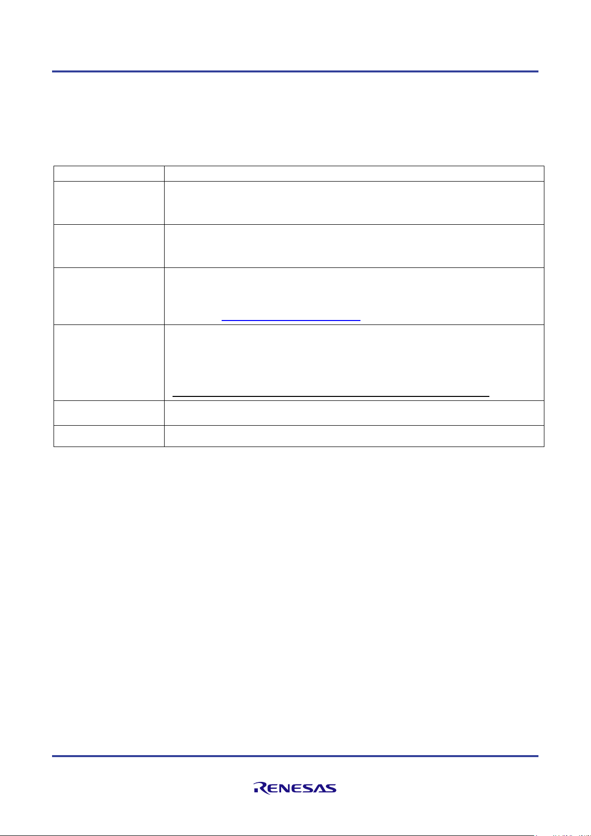
Linux Interface Specification Yocto recipe Start-Up Guide
Equipment
Explanation
Linux Host PC
Ubuntu 18.04 LTS (64bit) is recommended as OS. 32bit version is not supported.
It is used as building and debugging environment.
It is used as TFTP server and NFS server.
Windows Host PC
Windows 10 is recommended as OS.
It is used as debugging environment.
Terminal software and VCP driver are executed.
Terminal software
Please use following software.
1) Tera Term
(Confirmed with Japanese version of Tera Term 4.88
Available at http://sourceforge.jp/projects/ttssh2 )
VCP driver
Please install in Windows Host PC.
Execute CP210xVCPInstaller_x86/x64.exe for install before connect. USB become virtual
COM port on terminal software. Please connect to Serial-USB Bridge on RZG2 System
Evaluation Board
(Available at
http://www.silabs.com/products/mcu/Pages/USBtoUARTBridgeVCPDrivers.aspx)
TFTP server software
It is used when SPI Flash is written by U-Boot or Image is downloaded.
NFS server software
It is used when File system is mounted by NFS.
1.2 Environmental Requirement
Host PC and terminal software are necessary for the operation of this product. Furthermore, Ethernet cable is required to
use NFS mount function. Please refer to Table 1.
Table 1 RZ/G2 Linux BSP Environmental Requirement
R01US0398EJ017 Rev.1.07 Page 3 of 32
Feb. 26, 2021
Page 12
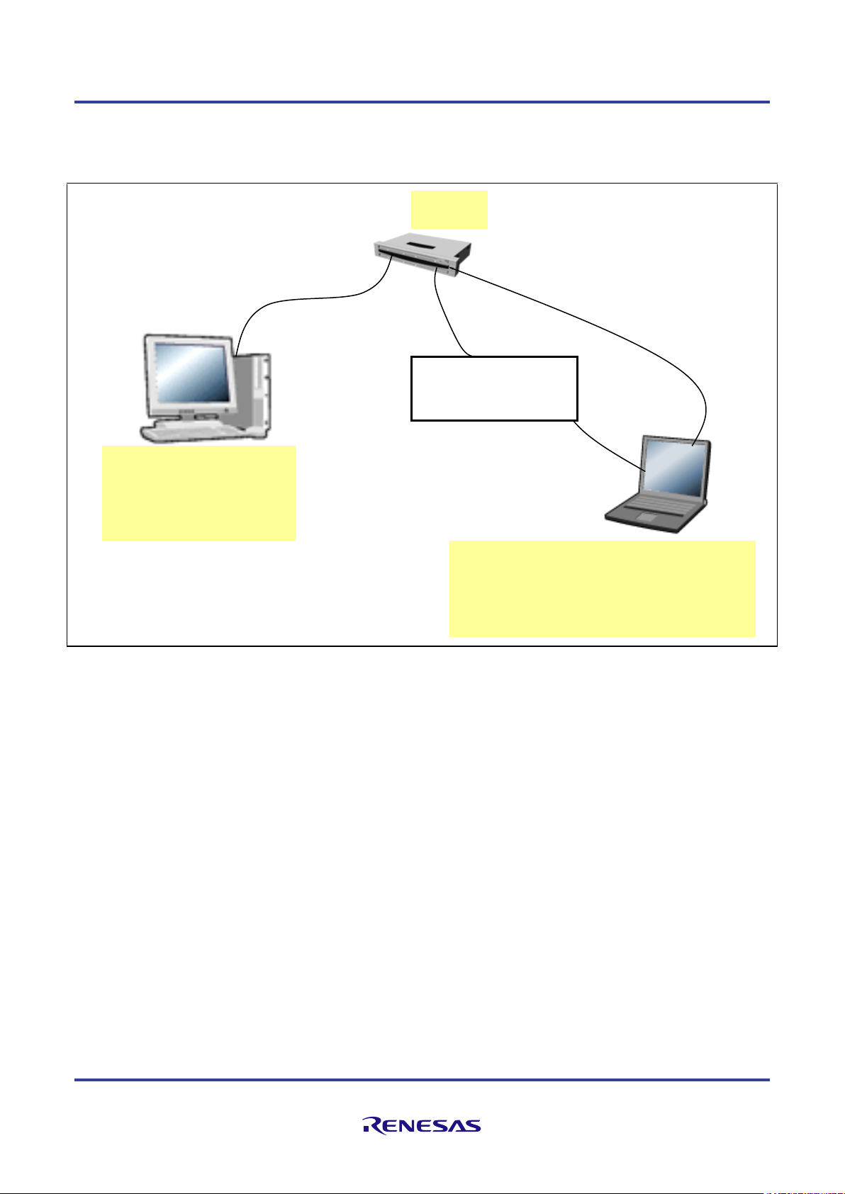
Linux Interface Specification Yocto recipe Start-Up Guide
Hub
[Linux Host PC]
NFS server
Straight Ethernet cable
USB cable (type A
[Windows 10 Host PC]
(ssh to control Linux Host)
(Straight Ethernet cable)
RZ/G2
System Evaluation Board
Recommended Environment
The following shows a Recommended Environment.
to mini/micro AB)
TFTP server
Figure 1. Recommended Environment for RZ/G2 Linux BSP
Note) Functions in covered with () are optional.
Terminal software to display console
R01US0398EJ017 Rev.1.07 Page 4 of 32
Feb. 26, 2021
Page 13
Linux Interface Specification Yocto recipe Start-Up Guide
$ sudo apt-get install gawk wget git-core diffstat unzip texinfo gcc-multilib \
build-essential chrpath socat libsdl1.2-dev xterm cpio python python3 \
python3-pip python3-pexpect xz-utils debianutils iputils-ping libssl-dev
$ cd ${WORK}
$ git clone git://git.yoctoproject.org/poky
$ git clone git://git.linaro.org/openembedded/meta-linaro.git
$ git clone git://git.openembedded.org/meta-openembedded
$ git clone https://github.com/renesas-rz/meta-rzg2.git
$ git clone http://git.yoctoproject.org/cgit.cgi/meta-gplv2
$ git clone https://github.com/meta-qt5/meta-qt5.git
2. Building Instructions
You can build BSP by using Yocto Project. Please execute following steps in ${WORK} directory on Linux Host PC.
Filesystem by making following instruction is the one for testing current BSP package in Renesas. Please note that
Renesas has not been verified with any other build configuration or modified recipes except “core-image-weston”
configuration which is based on upstream Yocto Project deliverables and some additional packages correspond to
gstreamer.
Note) Renesas executed following instructions with clean ${WORK}/build directory. You may use wipe-sysroot and/or
bitbake -c cleansstate to reflect modifications of configuration files for Recipe as in open source Yocto Project’s
standards, however Renesas strongly recommends to use recipe with clean ${WORK}/build directory for each
configurations because there are some implicit dependency for header files exist to keep compatibility between
application build scheme with/without proprietary software.
Step 1 installation of required commands
Ubuntu is used as Linux Host PC since Yocto Project Quick Start specifies Ubuntu as one of the distribution. In case of
that you can install the required commands as follows.
Please refer to http://www.yoctoproject.org/docs/current/yocto-project-qs/yocto-project-qs.html for detail.
Note) There is a bitbake command in ${WORK}/poky/scripts/. Command path is available after step 6.
Note) When you use terminal interactions to build such as menuconfig under non-X terminal (ssh, etc.), please install
“screen” command package to Host PC.
Note) Please set up user name and e-mail in Git. You can set up with ‘git config --global’. Please refer to online manual
for git command.
Note) In Renesas environment, Ubuntu version is 18.04 LTS and git version is 2.7.4. Step 2 download of required files
Required files (poky, meta-linaro) are downloaded by git clone.
R01US0398EJ017 Rev.1.07 Page 5 of 32
Feb. 26, 2021
Page 14

Linux Interface Specification Yocto recipe Start-Up Guide
$ cd ${WORK}/poky
$ git checkout -b tmp 7e7ee662f5dea4d090293045f7498093322802cc
$ cd ${WORK}/meta-linaro
$ git checkout -b tmp 75dfb67bbb14a70cd47afda9726e2e1c76731885
$ cd ${WORK}/meta-openembedded
$ git checkout -b tmp 352531015014d1957d6444d114f4451e241c4d23
$ cd ${WORK}/meta-gplv2
$ git checkout -b tmp f875c60ecd6f30793b80a431a2423c4b98e51548
$ cd ${WORK}/meta-qt5
$ git checkout -b tmp c1b0c9f546289b1592d7a895640de103723a0305
$ cd ${WORK}/meta-rzg2
$ git checkout -b tmp <tag>
<tag> : please check and choose the latest tag by ‘git tag’
$ git tag
….
BSP-1.0.6
BSP-1.0.7-RT
….
“-RT” is for Linux Realtime support
Copy All Proprietary Software Packages to ${PKGS_DIR}:
$ mkdir ${PKGS_DIR}
$ cp <zip of Proprietary Software Package> ${PKGS_DIR}
Install them into recipe directory structure by shell script:
$ cd ${WORK}/meta-rzg2
$ sh docs/sample/copyscript/copy_proprietary_softwares.sh ${PKGS_DIR}
Step 3 checkout
Please checkout available version of each git clone.
Note) tmp is a temporary name of a local branch. We can use checkout command without branch. Please note that HEAD
refers directly to commit (detached HEAD).
Step 4 copy proprietary software into recipe directory structure
To use licensed 3D graphics software and Multimedia package from Renesas, please copy deliverables of those software
into recipe directory structure. Renesas provide shell script to copy those software.
Note) Subdirectory is not supporting in ${PKGS_DIR}. Please store all packages on the root of ${PKGS_DIR}.
Note) Please use regular alphanumeric file name ([A-Za-z0-9_] e.g.) for ${PKGS_DIR} due to restrictions of current
copy script.
R01US0398EJ017 Rev.1.07 Page 6 of 32
Feb. 26, 2021
Page 15

Linux Interface Specification Yocto recipe Start-Up Guide
No.
Functions
Explanation
1
MMNGR
Memory manager driver & shared libraries
2
VSPM
VSP driver & FDP driver & shared libraries
3
VSP2
VSP2 driver
4
OMX
OMX common parts
$ cd ${WORK}
$ source poky/oe-init-build-env
$ cp ${WORK}/meta-rzg2/docs/sample/conf/<supported board
name>/<toolchain>/*.conf ./conf/.
For example
[Disable]
#DISTRO_FEATURES_append = " h264dec_lib"
[Enable (default)]
DISTRO_FEATURES_append = " h264dec_lib”
Step 5 execute source command
Please execute source command with oe-init-build-env for setting environment.
Step 6 copy bblayers.conf and local.conf
Please copy configuration files from deliverables.
Note) <supported board name> is the one of the following: ek874, hihope-rzg2m, hihope-rzg2n, hihope-rzg2h.
<toolchain> is the one of the following: poky-gcc, linaro-gcc
Step 7 enable Multimedia package
Please modify configurations in ${WORK}/build/conf/local.conf by following instructions.
The following standard multimedia packages are enabled
To enable optional multimedia functions, please add DISTRO_FEATURES_append to ${WORK}/build/conf/local.conf
as DISTRO_FEATURES_append = “ <function name>”.
Note) These configurations exist near the end of local.conf.
Note) DISTRO_FEATURES_append are commented out by the default. To enable functions, please uncomment it.
R01US0398EJ017 Rev.1.07 Page 7 of 32
Feb. 26, 2021
Page 16

Linux Interface Specification Yocto recipe Start-Up Guide
No.
Function name
Default
value
Explanation
1
h264dec_lib
Enable
H264 decoder library
RTM0AC0000XV264D30SL41C
2
h264enc_lib
Enable
H264 encoder library
RTM0AC0000XV264E30SL41C
3
h265dec_lib
Enable
H265 decoder library
RTM0AC0000XV265D30SL41C
No.
Function name
Type Name
Dependent Packages
1
h264dec_lib
RTM0AC0000XV264D30SL41C
RTM0AC0000XVCMND30SL41C
RTM0AC0000XCMCTL30SL41C
RCG3VUDRL4101ZDO
2
h264enc_lib
RTM0AC0000XV264E30SL41C
RTM0AC0000XVCMNE30SL41C
RTM0AC0000XCMCTL30SL41C
RCG3VUDRL4101ZDO
3
h265dec_lib
RTM0AC0000XV265D30SL41C
RTM0AC0000XVCMND30SL41C
RTM0AC0000XCMCTL30SL41C
RCG3VUDRL4101ZDO
The following list is package name to enable/disable as optional multimedia functions
The following list is dependent package name
R01US0398EJ017 Rev.1.07 Page 8 of 32
Feb. 26, 2021
Page 17

Linux Interface Specification Yocto recipe Start-Up Guide
No.
Function
Default
support
How to
1
Support GPLv3,
GPLv3+ softwares
No
Default in local.conf:
INCOMPATIBLE_LICENSE = "GPLv3 GPLv3+"
To enable:
#INCOMPATIBLE_LICENSE = "GPLv3 GPLv3+"
2
Support 32 bits
application
Yes
Default in local.conf:
require conf/multilib.conf
MULTILIBS = "multilib:lib32"
DEFAULTTUNE_virtclass-multilib-lib32 = "armv7vethf-neon-vfpv4"
USE_32BIT_PKGS = "1"
To disable:
#require conf/multilib.conf
#MULTILIBS = "multilib:lib32"
#DEFAULTTUNE_virtclass-multilib-lib32 = "armv7vethf-neon-vfpv4"
#USE_32BIT_PKGS = "1"
3
Support CIP Core
(Buster-full, Busterlimited, Jessie or
None)
Buster-full
Default in local.conf without support GPLv3, GPLv3+ softwares:
CIP_MODE = “Buster-full"
#BBMASK_append_cipcore = "|perl_debian”
INCOMPATIBLE_LICENSE = "GPLv3 GPLv3+"
To switch to:
Buster-full with support GPLv3, GPLv3+ softwares:
CIP_MODE = “Buster-full"
#BBMASK_append_cipcore = "|perl_debian”
#INCOMPATIBLE_LICENSE = "GPLv3 GPLv3+"
Buster-limited:
CIP_MODE = “Buster-limited"
Jessie:
CIP_MODE = “Jessie"
None:
CIP_MODE = “None"
or
#CIP_MODE = “Buster-full"
4
Support Docker
No
Default in local.conf:
#MACHINE_FEATURES_append = " docker"
To enable:
MACHINE_FEATURES_append = " docker"
Step 8 enable/disable other functions
Please modify configurations in ${WORK}/build/conf/local.conf by following instructions.
R01US0398EJ017 Rev.1.07 Page 9 of 32
Feb. 26, 2021
Page 18

Linux Interface Specification Yocto recipe Start-Up Guide
$ cd ${WORK}/build
$ bitbake <core-image-target>
<core-image-target> can be:
core-image-bsp : basic BSP suport
core-image-weston : BSP with MMP and Graphic support
core-image-qt : BSP with MMP, Graphic and Qt support
core-image-hmi : BSP with MMP, Graphic and hmi demos
Step 9 building with bitbake
Please build as follows. The file system (<core-image-target>-<supported board name>.tar.bz2) is created in
${WORK}/build/tmp/deploy/images/<supported board name>/ directory.
Note) <supported board name> is the one of the following: ek874, hihope-rzg2m, hihope-rzg2n, hihope-rzg2h.
<core-image-target> is the one of the following: core-image-bsp, core-image-weston, core-image-qt, core-image-hmi
Note) Build by bitbake might need several hours under the influence of Linux Host PC performance and network
environment.
Note) The bitbake downloads some package while building. Then the bitbake might stop for network timeout or link
error. In this case, please get applicable package in ${WORK}/build/downloads directory whenever build stops by wget
command, or please review timeout definitions of package download (wget, etc.) described in
${WORK}/poky/meta/conf/bitbake.conf.
R01US0398EJ017 Rev.1.07 Page 10 of 32
Feb. 26, 2021
Page 19

Linux Interface Specification Yocto recipe Start-Up Guide
Filename
Program Top
Address
Flash Save
Address
Description
bootparam_sa0.srec
0xE6320000
0x000000
Loader(Boot parameter)
bl2-<board>.srec
0xE6304000
0x040000
Loader
cert_header_sa6.srec
0xE6320000
0x180000
Loader(Certification)
bl31-<board>.srec
0x44000000
0x1C0000
ARM Trusted Firmware
tee-<board>.srec
0x44100000
0x200000
OP-Tee
u-boot-elf-<board>.srec
0x50000000
0x300000
U-Boot
Switch
Number
Pin1
Pin2
Pin3
Pin4
Pin5
Pin6
SW12
OFF
OFF
OFF - -
-
Switch
Number
Pin1
Pin2
Pin3
Pin4
Pin5
Pin6
SW12
ON
ON
ON - -
-
Switch
Number
Pin1
Pin2
Pin3
Pin4
Pin5
Pin6
Pin7
Pin8
SW1002
ON
ON
ON
ON
OFF
OFF
OFF
OFF
Switch
Number
Pin1
Pin2
Pin3
Pin4
Pin5
Pin6
Pin7
Pin8
SW1002
ON
ON
ON
ON
ON
OFF
ON
ON
3. Writing of IPL/Secure
3.1 Writing data
Note) <board>: ek874, hihope-rzg2m, hihope-rzg2n, hihope-rzg2h.
3.2 Dip-Switch
3.3 Switch setting for EK874 (RZG2E)
a) SCIF Download Mode
b) Boot Mode
3.4 Switch setting for HiHope-RZG2M, HiHope-RZG2N and HiHope-RZG2H
a) SCIF Download Mode
b) Boot Mode
R01US0398EJ017 Rev.1.07 Page 11 of 32
Feb. 26, 2021
Page 20

Linux Interface Specification Yocto recipe Start-Up Guide
SCIF Download mode (w/o verification)
(C) Renesas Electronics Corp.
-- Load Program to SystemRAM --------------please send !
RZ/G2 Scif Download MiniMonitor V1.00 2019.04.12
Work Memory : SystemRAM
Board Judge : Used Board-ID
Board Name : HiHope RZ/G2M
Product Code : RZ/G2M ES1.1
>xls2
===== Qspi/HyperFlash writing of Gen3 Board Command =============
Load Program to Spiflash
Writes to any of SPI address.
Winbond : W25M512JV
Program Top Address & Qspi/HyperFlash Save Address
===== Please Input Program Top Address ============
Please Input : H'
3.5 How to write
Please connect RZ/G2 System Evaluation Board, Windows Host PC with terminal software for console and Linux Host
PC.
Step 1 connect cable
Connect USB Host connector of Windows Host PC that is virtual COM port to RZ/G2 System Evaluation Board with
USB cable for displaying console.
Step 2 setting the terminal software
Activate the Terminal Software on Windows Host PC. Configure the Terminal Software on Windows Host PC as
followings. Please refer to Table 1 about the VCP driver for making a USB host connector into a virtual COM port.
[setting value] baud rate 115200, 8bit data, parity none, stop 1 bit, flow control none.
Step 3 write data file to SPI Flash
A file is written in SPI Flash in the following procedures.
Set dip switch “SCIF download mode”.
Reset board then start SCIF download mode.
After “Please send !” displayed, In case of Tera Term, transmit file
AArch64_Flash_writer_SCIF_DUMMY_CERT_E6300400_<board_name>.mot which is stored in
${WORK}/build/tmp/deploy/images/<board_name>, by "File -> Send file (S)".
Execute xls2 command (load program to flash).
After "Please Input Program Top Address" is displayed, input Program Top Address in 3.1 and "Enter".
After "Please Input Qspi/HyperFlash Save Address" is displayed, input Flash Save Address in 3.1 and "Enter".
R01US0398EJ017 Rev.1.07 Page 12 of 32
Feb. 26, 2021
Page 21

Linux Interface Specification Yocto recipe Start-Up Guide
After "Please send ! ('.' & CR stop load)" is displayed, In case of Tera Term, transmit files in 3.1 by "File -> Send file
(S)".
If there are some data in writing area, "SPI Data Clear(H'FF) Check :H'00000000-0003FFFF Clear OK?(y/n)" is
displayed. Then input "y".
After "SAVE SPI-FLASH ....... complete!" is displayed, the prompt returns. It means finish.
Please repeat the xls2 command, if other files are written.
Power OFF.
Set dip switch to “Boot Mode”.
3.6 IPL/Secure write
Please write the file described in Chapter 4.1 to SPI Flash.
The data file is stored in the ${WORK}/build/tmp/deploy/images/<board_name> directory.
R01US0398EJ017 Rev.1.07 Page 13 of 32
Feb. 26, 2021
Page 22

Linux Interface Specification Yocto recipe Start-Up Guide
Filename
Program Top Address
Flash Save Address
Description
u-boot-elf-*.srec
0x50000000
0x300000
U-Boot
=> setenv ethaddr xx:xx:xx:xx:xx:xx
=> setenv ipaddr 192.168.0.20
=> setenv serverip 192.168.0.1
=> setenv bootcmd 'tftp 0x48080000 Image;tftp 0x48000000 Image<SOC_FAMILY>-<Device_Tree>;booti 0x48080000 - 0x48000000'
4. Confirm starting of U-Boot and Linux
Please connect RZ/G2 System Evaluation Board, Windows Host PC with terminal software for console and Linux Host
PC with TFTP and NFS server as Figure 1. Then please confirm normal starting of U-Boot and Linux with following
step. Please refer to 2.2 for dip switch setting.
Step 1 setting Linux Host PC
Please install TFTP server and NFS server in Linux Host PC with apt-get command and so on. Please set
/etc/xinetd.d/tftp of TFTP server and /etc/exports of NFS server according to your environment.
Step 2 connect cable
Connect USB Host connector of Windows Host PC that is virtual COM port to RZ/G2 System Evaluation Board with
USB cable for displaying console.
Step 3 setting the terminal software
Activate the Terminal Software on Windows Host PC. Configure the Terminal Software on Windows Host PC as
followings. Please refer to Table 1 about the VCP driver for making a USB host connector into a virtual COM port.
[setting value] baud rate 115200, 8bit data, parity none, stop 1 bit, flow control none.
Step 4 write U-Boot to SPI Flash
Note) *: ek874, hihope-rzg2m, hihope-rzg2n, hihope-rzg2h.
The data file is stored in the ${WORK}/build/tmp/deploy/images/<board_name> directory.
Refer to Chapter 4.3 Step3 for write procedure.
Step 5 set U-Boot environment variables
Please refer to 2.2 for dip switch setting.
Please start U-Boot by board reset. Please set and save environment variable as follows.
Note) <SOC_FAMILY> is the following: r8a774c0, r8a774a1, r8a774a3, r8a774b1, r8a774e1.
Note) For RZ/G2E (SOC_FAMILY r8a774c0), the device trees are as follow:
R01US0398EJ017 Rev.1.07 Page 14 of 32
Feb. 26, 2021
Page 23

Linux Interface Specification Yocto recipe Start-Up Guide
=> setenv bootargs 'rw root=/dev/nfs nfsroot=192.168.0.1:/export/rfs
ip=192.168.0.20'
$ mkdir /export/rfs
$ cd /export/rfs
$ sudo tar xvf core-image-weston(bsp|qt|hmi)-<supported board
name>.tar.bz2
=> saveenv
- Image-r8a774c0-ek874*.dtb. (for the Board Revision E)
- Image-r8a774c0-ek874-revc*.dtb. (for the Board Revision C)
- Image-r8a774c0-esXX-ek874*.dtb. (for the oldest version of LSI)
Note) For RZ/G2M v1.3 (SOC_FAMILY r8a774a1), the device trees are as follow:
- Image-r8a774a1-hihope-rzg2m-ex*.dtb (for latest version of Board)
- Image-r8a774a1-hihope-rzg2m-rev2-ex*.dtb (for an old version of Board)
Note) For RZ/G2M v3.0 (SOC_FAMILY r8a774a3), the device trees are as follow:
- Image-r8a774a3-hihope-rzg2m-ex*.dtb (for latest version of Board)
Note) For RZ/G2N (SOC_FAMILY r8a774b1), the device trees are as follow:
- Image-r8a774b1-hihope-rzg2n-ex*.dtb (for latest version of Board)
- Image-r8a774b1-hihope-rzg2n-rev2-ex*.dtb (for an old version of Board)
Note) For RZ/G2H (SOC_FAMILY r8a774e1), the device trees are as follow:
Image-r8a774e1-hihope-rzg2h-ex*.dtb (for latest version of Board)
Step 6 change the bootargs by U-Boot
To change bootargs which passed to the kernel in boot sequence, please modify it by “setenv bootargs” command of UBoot.
Step 7 save environment variables
Step 8 set file system
Please extract file system (core-image-weston(bsp|qt|hmi)-<supported board name>.tar.bz2). Please export /export
directory of NFS server.
R01US0398EJ017 Rev.1.07 Page 15 of 32
Feb. 26, 2021
Page 24

Linux Interface Specification Yocto recipe Start-Up Guide
Note) <supported board name> is the following: ek874, hihope-rzg2m, hihope-rzg2n, hihope-rzg2h. Step 9 start Linux
After board reset, U-Boot is started. After countdown, Linux boot messages are displayed. Please confirm login prompt
after Linux boot messages.
Note) When MAC Address is rewritten, it is necessary to reset.
R01US0398EJ017 Rev.1.07 Page 16 of 32
Feb. 26, 2021
Page 25

Linux Interface Specification Yocto recipe Start-Up Guide
On ${WORK}/build/conf/local.conf
# This variable specified the architecture to build SDK/ADT items for and means
# you can build the SDK packages for architectures other than the machine you are
# running the build on (i.e. building i686 packages on an x86_64 host.
# Supported values are i686 and x86_64
#SDKMACHINE ?= "i686"
SDKMACHINE ?= "x86_64"
$ export PKG_CONFIG_PATH=$OECORE_NATIVE_SYSROOT/usr/lib/pkgconfig
$ unset PKG_CONFIG_SYSROOT_DIR
5. Exporting Toolchains
Please refer Documents from Yocto Project to export Toolchains such as
http://www.yoctoproject.org/docs/current/adt-manual/adt-manual.html.
And please use build target of bitbake as “core-image-weston(qt)-sdk -c populate_sdk” to generate package.
Note) When you use “ld” directly but not via gcc (in case of building Kernel, Driver or U-Boot), please disable
LDFLAGS with ‘unset LDFLAGS’. Furthermore, in kernel build, ‘make menuconfig’ occurs error by ncurses. In this
case, please set PKG_CONFIG_PATH and disable PKG_CONFIG_SYSROOT_DIR.
Note) Please do not use same shell environment to other compilation/debugging purpose (also make menuconfig of linux
kernel, e.g.) but cross compilation for RZ/G2E|G2M|G2N|G2H which shell environment with “source” command to
setup environment variables for the SDK. Because some environment variables for cross compilation interferes execution
of other tools on the same shell environment.
Example of instruction:
In following examples, it’s assumed that it’s already extracted and prepared recipe environment such as in the
instructions of Section 3 (must done just before execution of bitbake, at least). You may reuse ${WORK}/build while
you reuse same configuration after executing bitbake as in Section 3 for this purpose.
Step 1 configure architectures of Host PC which are installed this toolchain
Please modify SDKMACHINE description on ${WORK}/build/conf/local.conf.
Note) 32bit Ubuntu is not supported.
Ubuntu 16.04 and Ubuntu 18.04 can be used to build BSP and SDK, but when install SDK should use Ubuntu 18.04.
(If install SDK to Ubuntu 16.04, an error will appear. If ignore that error, installed SDK can still be used to build user
applications, but building kernel or kernel modules is not possible)
R01US0398EJ017 Rev.1.07 Page 17 of 32
Feb. 26, 2021
Page 26

Linux Interface Specification Yocto recipe Start-Up Guide
$ cd ${WORK}/build
$ bitbake core-image-weston(qt)-sdk -c populate_sdk
$ cp tmp/deploy/sdk/poky-glibc-x86_64-core-image-weston(qt)-sdkaarch64-toolchain-2.4.3.sh (shared dir. where able to access from each Host
PCs)
$ sudo (shared dir. where able to access from each Host PCs)/poky-glibcx86_64-core-image-weston(qt)-sdk-aarch64-toolchain-2.4.3.sh
[sudo] password for (INSTALL person): (password of your account)
Enter target directory for SDK (default: /opt/poky/2.4.3): (just a return)
Extracting SDK...done
Setting it up...done
$ cd (Your working directory)
$ source /opt/poky/2.4.3/environment-setup-aarch64-poky-linux
$ export LDFLAGS=””
$ ${CC} (Your source code).c …..
Compile also drivers which will not load (COMPILE_TEST) [N/y/?] <Enter>
Local version - append to kernel release (LOCALVERSION) [-yocto-standard] -yoctostandard
Automatically append version information to the version string
(LOCALVERSION_AUTO) [Y/n/?] <Enter>
…
SDK has been successfully set up and is ready to be used.
Each time you wish to use the SDK in a new shell session, you need to source the
environment setup script e.g.
$ . /opt/poky/2.4.3/environment-setup-aarch64-poky-linux
$ . /opt/poky/2.4.3/environment-setup-armv7vehf-neon-pokymllib32-linux-gnueabi
Step 2 building toolchain package with bitbake
Note) Please perform “bitbake core-image-minimal -c populate_sdk” in BSP Only.
Step 3 Install toolchain on each Host PCs
When it request to re configure please just enter to keep default value
Step 4 setup environment variables for each compilation on each Host PCs
Please setup environment variables as follows or integrate set-up sequence into your build script or Makefile.
R01US0398EJ017 Rev.1.07 Page 18 of 32
Feb. 26, 2021
Page 27

Linux Interface Specification Yocto recipe Start-Up Guide
6. Memory map
Following from Figure 2 to Figure 6 show memory map of this RZ/G2E|G2M|G2N|G2H Linux BSP package.
Note)
- The volume of SDRAM is total 2GB (RZ/G2E System Evaluation Board EK874), 4GB (RZ/G2M System
Evaluation Board HiHope-RZG2M), 4GB (RZ/G2N System Evaluation Board HiHope-RZG2N), 4GB (RZ/G2H
System Evaluation Board HiHope-RZG2H).
- 2GB from 0x00_4000_0000 to 0x00_BFFF_FFFF is a shadow area from 0x04_0000_0000 to 0x04_7FFF_FFFF.
- The following regions are used as a secure region. It doesn’t allow U-Boot and kernel to access those regions.
63MB from 0x00_43F0_0000 to 0x00_47DF_FFFF in SDRAM
16KB from 0x00_E630_0000 to 0x00_E630_3FFF in System RAM
- In case the configuration of BSP + 3D Graphics + Multimedia package, it doesn't allow to store any data in
"CMA for Lossy comp" (default: 0x00_5400_0000 - 0x00_56FF_FFFF) region which is for media playback
before kernel boots up. Any data stored in this region are read through the decompression module in AXIBus, so a normal data (not a decoded frame) will be corrupted.
R01US0398EJ017 Rev.1.07 Page 19 of 32
Feb. 26, 2021
Page 28

Linux Interface Specification Yocto recipe Start-Up Guide
BSC
0x0
Physical Address
Reserved
PCI-exp
0x00_2000_0000
0x00_3000_0000
Reserved
0x00_4000_0000
0x00_C000_0000
IO area
0x00_E000_0000
0x01_0000_0000
~
~ ~ ~
0x04_0000_0000
0x05_0000_0000
0x06_0000_0000
0x07_0000_0000
SPI Flash
0x00_4000_0000
0x00_C000_0000
0x06_8000_0000
0x00_4800_0000
0x00_5000_0000
ARM Trusted
Firmware
U-Boot
ARM Trusted Firmware
Certification
IPL
Boot parameter
System RAM
Boot parameter
IPL
ROM program
0x08_0000_0000
0x00_E630_0000
Region
0x04_8000_0000
0x180000
0x040000
0x0
0x1C0000
0x300000
Certification
0x00_43F0_0000
0x00_47E0_0000
Option
Region
0x00_8000_0000
0x04_4000_0000
U-Boot
Secure
SDRAM 2GB
Legacy
Shadow area
SDRAM 2GB
N/A
N/A
N/A
N/A
N/A
Load by Boot
Secure
R01US0398EJ017 Rev.1.07 Page 20 of 32
Feb. 26, 2021
Figure 2. RZ/G2E System Evaluation Board EK874 memory map (Boot)
Page 29

Linux Interface Specification Yocto recipe Start-Up Guide
BSC
0x0
Physical Address
Reserved
PCI-exp
0x00_2000_0000
0x00_3000_0000
Reserved
0x00_4000_0000
0x00_C000_0000
IO area
0x00_E000_0000
0x01_0000_0000
~
~
~
~
0x04_0000_0000
0x05_0000_0000
0x06_0000_0000
0x07_0000_0000
0x00_4000_0000
0x06_8000_0000
0x00_4800_0000
0x00_4808_0000
ARM Trusted Firmware
0x08_0000_0000
Region
0x04_8000_0000
Certification
0x00_43F0_0000
0x00_47E0_0000
0x00_C000_0000
0x00_5800_0000
Option
0x00_8000_0000
0x04_4000_0000
0x00_5700_0000
0x00_6800_0000
0x00_5400_0000
dtb
Kernel Image
CMA for MMP 128 MB
0x00_5020_0000
Secure
SDRAM 2GB
Legacy
Shadow area
SDRAM 2GB
N/A
N/A
N/A
CMA (256MB)
CMA 256 MB
N/A
R01US0398EJ017 Rev.1.07 Page 21 of 32
Feb. 26, 2021
N/A
Figure 3. RZ/G2E System Evaluation Board EK874 memory map (Linux)
Page 30

Linux Interface Specification Yocto recipe Start-Up Guide
BSC
0x0
Physical Address
Reserved
PCI-exp
0x00_2000_0000
0x00_3000_0000
Reserved
0x00_4000_0000
0x00_C000_0000
IO area
0x00_E000_0000
0x01_0000_0000
~
~
~
~
0x04_0000_0000
0x05_0000_0000
0x06_0000_0000
0x07_0000_0000
Hyper Flash
0x00_4000_0000
0x00_C000_0000
0x06_8000_0000
0x00_4800_0000
0x00_5000_0000
ARM Trusted
Firmware
U-Boot
ARM Trusted Firmware
OP-Tee
IPL
Certification
IPL
Boot parameter
System RAM
Boot parameter
IPL
ROM program
U-Boot
0x08_0000_0000
0x00_E630_0000
Region
0x04_8000_0000
0x180000
0x040000
0x0
0x1C0000
0x300000
Certification
0x00_43F0_0000
0x00_47E0_0000
Option
Region
Secure
SDRAM 2GB
Legacy
Shadow area
SDRAM 2GB
N/A
N/A
SDRAM 2GB
Load by
Load by Boot
Secure
N/A
N/A
R01US0398EJ017 Rev.1.07 Page 22 of 32
Feb. 26, 2021
Figure 4. RZ/G2M System Evaluation Board (HIHOPE-RZG2M) memory map (Boot)
Page 31

Linux Interface Specification Yocto recipe Start-Up Guide
BSC
0x0
Physical Address
Reserved
PCI-exp
0x00_2000_0000
0x00_3000_0000
Reserved
0x00_4000_0000
0x00_C000_0000
IO area
0x00_E000_0000
0x01_0000_0000
~
~
~
~
0x04_0000_0000
0x05_0000_0000
0x06_0000_0000
0x07_0000_0000
0x00_4000_0000
0x00_C000_0000
0x06_8000_0000
0x00_4800_0000
0x00_4808_0000
ARM Trusted Firmware
OP-Tee
dtb
0x08_0000_0000
Region
0x04_8000_0000
Certification
0x00_43F0_0000
0x00_47E0_0000
0x00_7800_0000
0x00_8800_0000
0x00_5800_0000
0x00_5700_0000
0x00_5400_0000
Option
Kernel Image
CMA for Lossy comp
(48MB)
Secure
SDRAM 2GB
Legacy
Shadow area
SDRAM 2GB
N/A
N/A
SDRAM 2GB
N/A
N/A
CMA
(512MB)
CMA for MMP
(256MB)
R01US0398EJ017 Rev.1.07 Page 23 of 32
Feb. 26, 2021
Figure 5. RZ/G2M System Evaluation Board (HiHope-RZG2M) memory map (Linux)
Page 32

Linux Interface Specification Yocto recipe Start-Up Guide
BSC
0x0
Physical Address
Reserved
PCI-exp
0x00_2000_0000
0x00_3000_0000
Reserved
0x00_4000_0000
0x00_C000_0000
IO area
0x00_E000_0000
0x01_0000_0000
~
~ ~ ~
0x04_0000_0000
0x05_0000_0000
0x06_0000_0000
0x07_0000_0000
SPI Flash
0x00_4000_0000
0x00_C000_0000
0x06_8000_0000
0x00_4800_0000
0x00_5000_0000
ARM Trusted
Firmware
U-Boot
ARM Trusted Firmware
Certification
IPL
Boot parameter
System RAM
Boot parameter
IPL
ROM program
0x08_0000_0000
0x00_E630_0000
Region
0x04_8000_0000
0x180000
0x040000
0x0
0x1C0000
0x300000
Certification
0x00_43F0_0000
0x00_47E0_0000
Option
Region
0x00_8000_0000
0x04_4000_0000
U-Boot
Secure
SDRAM 2GB
Legacy
Shadow area
SDRAM 2GB
SDRAM 2GB
N/A
N/A
N/A
N/A
Load by Boot
Secure
R01US0398EJ017 Rev.1.07 Page 24 of 32
Feb. 26, 2021
Figure 6. RZ/G2N System Evaluation Board (HiHope-RZG2N) memory map (Boot)
Page 33

Linux Interface Specification Yocto recipe Start-Up Guide
BSC
0x0
Physical Address
Reserved
PCI-exp
0x00_2000_0000
0x00_3000_0000
Reserved
0x00_4000_0000
0x00_C000_0000
IO area
0x00_E000_0000
0x01_0000_0000
~
~
~
~
0x04_0000_0000
0x05_0000_0000
0x06_0000_0000
0x07_0000_0000
0x06_8000_0000
0x08_0000_0000
Region
0x04_8000_0000
0x00_8000_0000
0x04_4000_0000
0x00_4000_0000
0x00_C000_0000
0x00_4800_0000
0x00_4808_0000
ARM Trusted Firmware
OP-Tee
dtb
Certification
0x00_43F0_0000
0x00_47E0_0000
0x00_7800_0000
0x00_8800_0000
0x00_5800_0000
0x00_5700_0000
0x00_5400_0000
Option
Kernel Image
CMA for Lossy comp
(48MB)
Secure
SDRAM 2GB
Legacy
Shadow area
SDRAM 2GB
SDRAM 2GB
N/A
CMA
(512MB)
CMA for MMP
(256MB)
N/A
N/A
N/A
R01US0398EJ017 Rev.1.07 Page 25 of 32
Feb. 26, 2021
Figure 7. RZ/G2N System Evaluation Board (HiHope-RZG2N) memory map (Linux)
Page 34

Linux Interface Specification Yocto recipe Start-Up Guide
BSC
0x0
Physical Address
Reserved
PCI-exp
0x00_2000_0000
0x00_3000_0000
Reserved
0x00_4000_0000
0x00_C000_0000
IO area
0x00_E000_0000
0x01_0000_0000
~
~
~
~
0x04_0000_0000
0x05_0000_0000
0x05_8000_0000
0x07_0000_0000
Hyper Flash
0x00_4000_0000
0x00_C000_0000
0x06_8000_0000
0x00_4800_0000
0x00_5000_0000
ARM Trusted
Firmware
U-Boot
ARM Trusted Firmware
OP-Tee
IPL
Certification
IPL
Boot parameter
System RAM
Boot parameter
IPL
ROM program
U-Boot
0x08_0000_0000
0x00_E630_0000
Region
0x04_8000_0000
0x180000
0x040000
0x0
0x1C0000
0x300000
Certification
0x00_43F0_0000
0x00_47E0_0000
Option
Region
0x06_0000_0000
Secure
SDRAM 2GB
Legacy
Shadow area
SDRAM 2GB
N/A
SDRAM 2GB
N/A
N/A
Load by Boot
Secure
N/A
N/A
Load by
R01US0398EJ017 Rev.1.07 Page 26 of 32
Feb. 26, 2021
Figure 8. RZ/G2H System Evaluation Board (HIHOPE-RZG2H) memory map (Boot)
Page 35

Linux Interface Specification Yocto recipe Start-Up Guide
BSC
0x0
Physical Address
Reserved
PCI-exp
0x00_2000_0000
0x00_3000_0000
Reserved
0x00_4000_0000
0x00_C000_0000
IO area
0x00_E000_0000
0x01_0000_0000
~
~
~
~
0x04_0000_0000
0x05_0000_0000
0x05_8000_0000
0x07_0000_0000
0x00_4000_0000
0x00_C000_0000
0x06_8000_0000
0x00_4800_0000
0x00_4808_0000
ARM Trusted Firmware
OP-Tee
dtb
0x08_0000_0000
Region
0x04_8000_0000
Certification
0x00_43F0_0000
0x00_47E0_0000
0x00_7800_0000
0x00_8800_0000
0x00_5800_0000
0x00_5700_0000
0x00_5400_0000
Option
Kernel Image
CMA for Lossy comp
(48MB)
0x06_0000_0000
Secure
SDRAM 2GB
Legacy
Shadow area
SDRAM 2GB
N/A
SDRAM 2GB
N/A
CMA
(512MB)
CMA for MMP
(256MB)
N/A
N/A
N/A
R01US0398EJ017 Rev.1.07 Page 27 of 32
Feb. 26, 2021
Figure 9. RZ/G2H System Evaluation Board (HiHope-RZG2H) memory map (Linux)
Page 36

Linux Interface Specification Yocto recipe Start-Up Guide
linux,cma {
compatible = "shared-dma-pool";
reusable;
reg = <0x00000000 0xXXXXXXXX 0x0 0xYYYYYYYY>;
linux,cma-default;
};
0xXXXXXXXX is start address of CMA region.
0xYYYYYYYY is size of CMA region.
Note)
- Kernel region is assigned by Kernel device tree arch/arm64/boot/dts/renesas/xxx.dts and totally mapped to 1920MB
(RZ/G2E System Evaluation Board EK874), 3968MB (RZ/G2M System Evaluation Board HiHope-RZG2M),
3968MB (RZ/G2N System Evaluation Board HiHope-RZG2N), 3968MB (RZ/G2H System Evaluation Board
HiHope-RZG2H)
Kernel region consists of 1 part: (RZ/G2E System Evaluation Board EK874)
1920MB from 0x00_4800_0000 to 0x00_BFFF_FFFF
Kernel region consists of 2 part: (RZ/G2M System Evaluation Board HiHope-RZG2M)
1920MB from 0x00_4800_0000 to 0x00_BFFF_FFFF
2GB from 0x06_0000_0000 to 0x06_7FFF_FFFF
Kernel region consists of 2 part: (RZ/G2N System Evaluation Board HiHope-RZG2N)
1920MB from 0x00_4800_0000 to 0x00_BFFF_FFFF
2GB from 0x04_8000_0000 to 0x04_EFFF_FFFF
Kernel region consists of 2 part: (RZ/G2H System Evaluation Board HiHope-RZG2H)
1920MB from 0x00_4800_0000 to 0x00_BFFF_FFFF
2GB from 0x05_0000_0000 to 0x05_7FFF_FFFF
There are three types of CMA regions.
They are defined in device tree (arch/arm64/boot/dts/renesas/xxxx.dts).
Default CMA region: It is for kernel, general drivers and multimedia package.
Note)
128 MB in this CMA (RZ/G2M (v1.3, v3.0) |G2N|G2H 512MB, RZ/G2E 256MB) is reserved
for kernel and general drivers, and the remaining RZ/G2M (v1.3, v3.0) |G2N|G2H 384 MB,
RZ/G2E 128MB is reserved for multimedia package.
The CMA region can be adjusted by changing the start address and the size.
Should take care of the lack of memory allocated by kernel and general drivers when reducing
the region size.
R01US0398EJ017 Rev.1.07 Page 28 of 32
Feb. 26, 2021
Page 37

Linux Interface Specification Yocto recipe Start-Up Guide
mmp_reserved: linux,multimedia {
compatible = "shared-dma-pool";
reusable;
reg = <0x00000000 0xXXXXXXXX 0x0 0xYYYYYYYY>;
};
0xXXXXXXXX is start address of CMA region.
0xYYYYYYYY is size of CMA region.
Virtual Address
0x0
0x0001_0000_0000_0000
0xFFFF_FFFF_FFFF_FFFF
0xFFFF_0000_0000_0000
vmalloc
vmemmap
・・・
Kernel
・・・
CMA region for MMP: It is for multimedia package (specific H/Ws).
Note)
Refer to User’s manual of Memory Manager in order to change CMA region for MMP.
N/A
User
(256TB)
Kernel
(256TB)
Figure 10 . RZ/G2 memory map (Virtual)
Note)
- Kernel uses 4KB page size (VA_BITS=48) and 4 levels of translation tables. Both regions of User and Kernel
are 256TB. Refer to Documentation/arm64/memory.txt.
- Detail information about kernel memory map in virtual address space, refer to User’s manual of Kernel.
R01US0398EJ017 Rev.1.07 Page 29 of 32
Feb. 26, 2021
Page 38

Linux Interface Specification Yocto recipe Start-Up Guide
7. U-Boot command
Please refer to U-Boot user's manual about available U-Boot command for RZ/G2 Linux BSP.
The help or “?” command shows U-Boot command list, but be careful that it includes some unsupported command.
R01US0398EJ017 Rev.1.07 Page 30 of 32
Feb. 26, 2021
Page 39

Linux Interface Specification Yocto recipe Start-Up Guide
Command
Description
systemctl stop watchdog
Stop Watchdog Service
systemctl start watchdog
Start Watchdog Service
systemctl restart watchdog
Restart Watchdog Service
systemctl disable watchdog
Disable Watchdog Service in root filesystem
systemctl enable watchdog
Enable Watchdog Service in root filesystem
/usr/bin/watchdog-test -d -t 60 -e
8. System Service
In RZ/G2 VLP64 environment, some services are added to root filesystem to assist related drivers.
8.1 Watchdog Service
Watchdog Service is a systemd service, which is used to generate a reset when system is freeze.
It is automatically loaded in root filesystem and runs background during operation with binary file:
This binary is compiled from “tools/testing/selftests/watchdog/watchdog-test.c” in kernel source code.
The meaning of each parameter:
-d: Turn off the watchdog timer
-t: set time out to 60s
-e: Turn on the watchdog timer
-p: set ping rate (default value is 1s if not set)
To control Watchdog Service interface, we can refer similar commands of systemd service on linux. The following table
show supported commands:
Table 2 Supported commands
Watchdog Service is automatically activated by default. To turn off Watchdog Service, please choose one of the
following ways:
Stop Watchdog Service in runtime (Turn off only once. If you reset or powering up board again, watchdog
service still starts again):
o systemctl stop watchdog.
Disable Watchdog Service in runtime (Turn off completely. If you reset or powering up board again, watchdog
service does not start):
o systemctl stop watchdog.
o systemctl disable watchdog.
R01US0398EJ017 Rev.1.07 Page 31 of 32
Feb. 26, 2021
Page 40

Linux Interface Specification Yocto recipe Start-Up Guide
Processor
CSI20
CSI40
RZ/G2H
VIN4/VC0
VIN0/VC0
RZ/G2M v1.3
VIN4/VC0
-
RZ/G2M v3.0
VIN4/VC0
VIN0/VC0
RZ/G2N
VIN4/VC0
VIN0/VC0
RZ/G2E
-
VIN4/VC0
IMAGE_INSTALL_append = " \
bash \
v4l-utils \
i2c-tools \
coreutils \
- watchdog \
IMAGE_INSTALL_append = " \
….
rt-tests \
ltp \
openssl \
- vin-init \
Remove Watchdog Service from BSP packages: remove “watchdog” package in “recipes-images/core-image-
renesas-base.inc”
8.2 Video Input Initializing Service
In RZ/G2 environment, there is a service named “vin” which automatically sets connecting among VIN, CSI2 and
OV5645 camera sensor.
This script automatically sets default links for:
To change the connection in runtime, user can use a script at “/home/root/vin-init.sh” created by vin service then
modify some parameters which are described in this script based on user’s purpose and connection tables (Table 4.3, 4.4,
4.5, 4.6 in Video Capture User’s Manual).
To remove “vin” service from BSP packages, please remove “vin-init” package in “recipes-images/core-image-bsp.inc”:
R01US0398EJ017 Rev.1.07 Page 32 of 32
Feb. 26, 2021
Page 41

REVISION HISTORY
Linux Interface Specification Yocto recipe Start-Up Guide
User’s Manual: Software
Rev.
Date
Description
Page
Summary
1.00
Apr. 2019
First Edition issued
1.01
Jun. 2019
__
Add support Hihope-RZG2M
1.02
Oct. 2019
__
Add support Hihope-RZG2N, remove ECC support, add lossy compress in memory
map
1.03
Jan. 2020
2, 6
Add information for Linux Realtime support
12
Add information where to get flash-writer
17
Correct SDK path to source the environment setup script
22,24,
25
Change memory map, global CMA for G2M, G2N increased to 512MB
1.04
Jun. 2020
__
Add support Hihope-RZG2H
1.05
Aug. 2020
__
Add support Hihope-RZG2M with RZ/G2M v3.0
31, 32
Add new chapter “8.System Service” which includes:
8.1 Watchdog Service
8.2 Video Input Initializing Service
1.06
Nov. 2020
9
Add description about “Support CIP Core”.
1.07
Feb. 2021
-
Add information about EK874 Board Revision E (RZ/G2E)
-
Update version of Linux Host PC from Ubuntu 16.04 LTS to 18.04 LTS
9
Add description about “Support Docker”
C - 1
Page 42

Linux Interface Specification Yocto recipe Start-Up Guide
User’s Manual: Software
Publication Date: Rev.1.07 Feb. 26, 2021
Published by: Renesas Electronics Corporation
Page 43

Linux Interface Specification
Yocto recipe Start-Up Guide
 Loading...