

Page 1

Application Note
Renesas Synergy™ Platform
Key Matrix HAL Module Guide
Introduction
This module guide will enable you to eff ectively use a module in your own design. Upon compl etion of this
guide, you will be able to add this module to your own design, configure it correctly for the target applic ation
and write code, using the included application project code as a r eference and efficient starting point .
References to more detailed API descri ptions and suggestions of other applicatio n projects that illustrate
more adv anced uses of the module are available in the Renesas Synergy Knowl edge Base (as described in
the References section at the end of this document), and should be v aluable resources for creating more
complex designs.
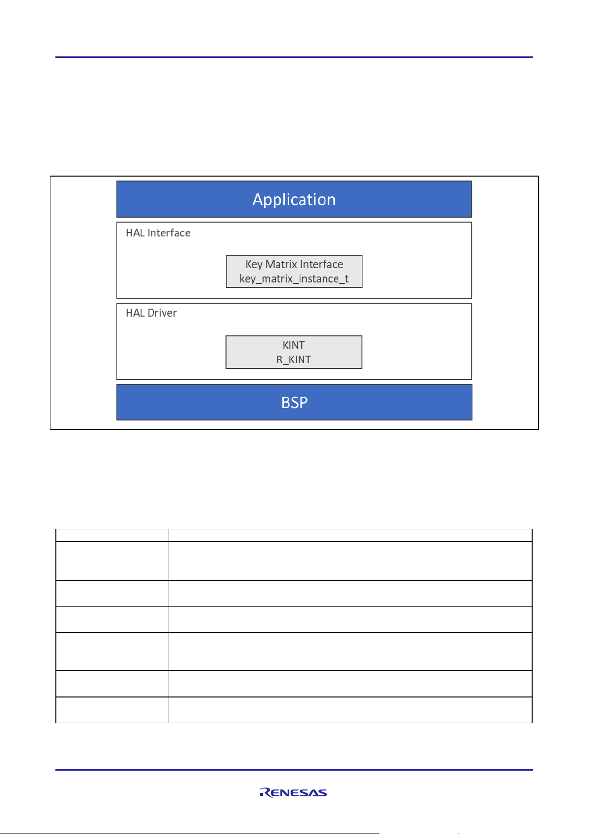
The Key Matrix HAL modul e is a high-level API for Key Matrix HAL applicatio ns and is implemented on
r_kint. The Key Matrix HAL module uses the key-interrupt function peripheral on the Sy nergy MCU. A userdefined callback can be created to inform the CPU of a key press event.
Contents
1. Key Matrix HAL Module Features ..........................................................................................2
2. Key Matrix HAL Module APIs Overview .................................................................................2
3. HAL Module Oper ational Over view ........................................................................................3
3.1 Key Matrix HAL Module Important Operational Notes and Li m itations ............................................ 3
3.1.1 Key Matrix HAL Module Operational Notes .............................................................................. 3
3.1.2 Key Matrix HAL Module Limitations ........................................................................................ 3
4. Including the Key Matrix HAL Module in an Application ..........................................................3
5. Configuring the Key Matrix HAL Module ................................................................................4
5.1 Key Matrix HAL Module Clock Configurati on .............................................................................. 5
5.2 Key Matrix HAL Module Pin Configurati on ................................................................................. 5
6. Using the Key Matrix HAL Module in an Application ...............................................................5
7. The Key Matrix HAL Module Application Project ....................................................................6
8. Customizing the Key Matr ix HAL Module for a Target Application.........................................10
9. Running the Key Matrix HAL Module Application Project ......................................................10
10. Key Matrix HAL Module Conclusion .....................................................................................10
11. Key Matrix HAL Module Next Steps .....................................................................................10
12. Key Matrix HAL Module Reference Information ....................................................................10
R11AN0123EU0102 Rev.1.02 Page 1 of 12
Feb.27.19
Page 2
Renesas Synergy™ Platform Key Matrix HAL Module Guide
Function N ame
Example A PI Call and Des criptio n
.open
g_keymatrix_on_kint.p_api->open(g_kint.p_ctrl,
.enable
g_keymatrix_on_kint.p_api->enable(g_kint.p_ctrl)
.disable
g_keymatrix_on_kint.p_api->disable(g_kint.p_ctrl)
Disable Key interrupt.
.triggerSet
g_keymatrix_on_kint.p_api->triggerSet(g_kint.p_ctrl,
Set trigger for Key interrupt.
.close
g_keymatrix_on_kint.p_api->close(g_kint.p_ctrl)
Allow driv er to be reconfigured. May reduce power consumption.
.versionGet
g_keymatrix_on_kint.p_api->versionGet(&version)
Get version and store it in provided pointer v ersion.
1. Key Matrix HAL Module Features
This Key Matrix HAL module configures and con trols the Key Interrupt (KINT) peripheral. It implements th e
following key functions:
• Supports both rising and falling edges on KINT channels
• Supports interrupt-based event notif icat ion
• Supports a bit-masking function to capt ure multiple events efficiently
• Supports a matrix keypad w ith edges on any two channels
Figure 1. Key Matrix HAL Module Block Diag ram
2. Key Matrix HAL Module APIs Overview
The Key Matrix HAL module def ines API s for opening, closing, enabling, and disabling key-interrupt
functions. A com plete list of the av ailable APIs, an example API call and a short description of each can be
found in the following table. A table of status return values follows the AP I summary table.
Table 1. Key Matrix HAL Module API Sum m a ry
g_kint.p_cfg)
Initial configuration.
Enable Key interrupt.
trigger)
Note: For details on operation and definitions for the function data struct ures, typedefs, defines, API data,
API structures and f unction v ar iables, rev iew the SSP User’ s Manual API R eferences for the
associated module.
R11AN0123EU0102 Rev.1.02 Page 2 of 12
Feb.27.19
Page 3

Renesas Synergy™ Platform Key Matrix HAL Module Guide
Name
Description
SSP_SUCCESS
Function successfully co mpleted.
SSP_ERR_ASSERTION
Parameter has invalid value.
SSP_ERR_INVALID_ARGUMENT
Argument is invalid.
SSP_ERR_HW_LOCKED
The API has already been opened. It must be closed before it
can be opened again.
SSP_ERR_NOT_OPEN
The peripheral is not opened.
Table 2. Sta tus Return Val ues
Note: Lower-level driver s may return common error codes. Refer to the SSP User’ s Manual API Ref erences
for the associated module for a definition of all relevant status return v alues.
3. HAL Module Operational Overview
The Key Matrix HAL module configures the Key Interrupt (KINT ) peripheral to detect rising or falling edges
on any of the KIN T channels. When such an event is detected on any of the configured pins, the module
generates an interrupt; the interrupt then calls the user callback ( p_callback) with t he callback argument
keymatrix_callback_args_t that s pecifies the channel(s) on w hich the edge was detected using a bitmask.
Even though detection of an edge on any one channel generates the interrupt, the callback returns a bitmask
keymatrix_channels_t of all the pins that w ere triggered at that time if any other pins also detected an edge.
Thus, an interrupt is not necessarily generated for edge detection on each pin if an edge was also detected
on another pin bef ore the callback was cal led. If a new edge is detected af ter the callback was c alled, then
the interrupt is triggered again, resulting in a new callback.
This module can be used to implement a matrix keypad with edges on any two channels indicati ng the act u al
key that was pressed; alternatively, the module can be used as a single input to detec t an edge on an input
pin.
3.1 Ke y M atrix HAL Module Important Operational Notes and Limitations
3.1.1 Key Matrix HA L Module Op eratio n al Not es
• To trigger a transf er of data using the DMAC or DT C peripheral when a trigger edge is detected,
configure the DMAC/DT C transf er with activation_source set to ELC_EVENT_KEY_INT.
• The KI NT module can trigger the start of other peripherals available to the ELC. For details, see the ELC
section in the SSP User’s Manual.
• You must enable the KI NT (I NT KR) interrupt in the BSP for this module to operate, regardless of w hether
a callback is used in the open call.
3.1.2 Key Matrix HA L Module Limitations
• This module does not support polling-mode operati on.
• Refer to the latest SSP Release N otes for any additional operational limitations for this module.
4. Including the Key Matrix HAL Module in an A pplication
This section describ es how to include the Key Matrix H AL module in an application using the SSP
configurator.
Note: It is assumed you are familiar with creating a project, adding threads, adding a stack to a thread and
configuring a block within the stack. If you are unfamiliar with any of these items, refer to the f irst few
chapters of the SSP User’s Manual to learn how to manage each of these important steps in creating
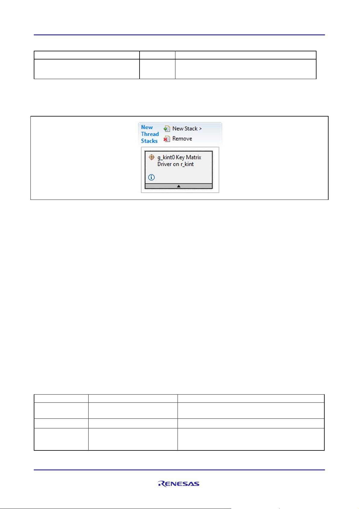
To add the Key Matrix Driv er to an application, simply add it to a thread using the stacks selection sequence
given in t he following table. (T he def ault name for the Key Matrix D riv er is g_kint0. T his name can be
changed in the associated Properties window.)
SSP-based applications.
R11AN0123EU0102 Rev.1.02 Page 3 of 12
Feb.27.19
Page 4
Renesas Synergy™ Platform Key Matrix HAL Module Guide
Resource
ISDE Tab
Stacks Selection Sequence
g_kint0 Key Matrix Driver on r_kint
Threads
New Stack> Driv er> Input> Key Matr ix Driv er on
ISDE Property
Value
Description
Parameter
BSP, Enabled, Disable d
(Default: BSP)
Enable or disable the parameter error checking.
Name
g_kint0
Module name
Keymatrix
Select Channels Below
This is a bit-mask with each bit specifyi ng if that
to be used.
Table 3. Key Matrix HAL Modu le Selection Seq uenc e
r_kint
When the Key Matrix Driver on r_kint is added to the thread stack as shown in the following figure, the
configurator automatical ly adds any needed lower-level modules. Any dr iv ers that need additional
configuration information is box text highlighted in Red. Modules with a Gray band are indiv idual modules
that stand alone.
Figure 2. Key Matrix HAL Module Stack
5. Configuring the Key Matrix HAL Module
The Key Matrix HAL module on r_kint must be configured by the user for the desired operation. T he SSP
configuration window automatically identifies (by highlighting the block in red) any required configuration
selections, suc h as int errupts or operating modes, which must be configured for lower-lev el modules for
successful operation. Only properties that can be change d without causing conflicts are av ailable for
modification. Other properties are ‘locked’ and are not av ailable for changes, and are identified with a lock
icon for the ‘locked’ property in the Properties window in the Integrated Sol ution Developer Environment
(ISDE). T his approach simplifies the configuration process and makes it much less error-pr one than previous
‘manual’ approaches to configuration. The available configuration settings and def aults for all the useraccessible properties are giv en in the properties tab within the SSP configurator, and are shown in the
following tables for easy reference.
One of the properties most often identified as requiring a change is the interrupt priority; this configuration
setting is av ailable within the Properties w indow of the associated module. Sim ply select the indicated
module and then v iew the properties window; the interrupt settings are often toward the bottom of the
properties list, so scroll down until they become available. Also note that the interrupt priorities listed in the
Properties window in the ISDE includes an indication as t o the v alidity of the setting based on the targeted
MCU (CM4 or CM0+). T his level of detail is not included in the following configuration properties tables, but
is easily v isible within the ISDE when configuring interrupt-priority lev els.
Note: You may want to open your ISDE, create the module and explore the property se ttings in parallel with
looking ov er the following configuration table settings. T his helps to orient you and can be a useful
‘hands-on’ approach to learning the ins and outs of developing with SSP.
Table 4. C onf igu rat io n Set tings for t he Key Mat rix HA L Module on r_ kin t
Checking
Channel Mask
R11AN0123EU0102 Rev.1.02 Page 4 of 12
Feb.27.19
channel is to be enabled or not. Select the channels
Page 5

Renesas Synergy™ Platform Key Matrix HAL Module Guide
ISDE Property
Value
Description
Channel 0:7
Unused, Used
Channel 0:7 selection.
Trigger Type
Rising Edge, Falling Edge
Specify if the enabled channels detect a rising edge
falling edge.
Interrupt enabled
True, Fals e
Specify if the module interrupts must be enabled as
Callback
NULL
Callback select ion.
Interrupt Priority
Priority 0 (highest),
(Default: Disabled)
Interrupt priority selection.
Resource
ISDE Tab
Pin s electio n Sequence
KINT
Pins
Select Peripherals > Input:KIN T > KI NT 0
Property
Value
Description
Operation Mode
Disabled, Custom
(Default: Disabled)
Select Custom as the Operation Mode
KRM0:7
None, Pnn
(Default: None)
Key Interrupt Pin selection
(Default: Unused)
(Default: Rising Edge)
after initialization
Note: The example v alues and defaults are for a project using the Synergy S7G 2 MCU Family. Other MC Us
may have different default values and av ailable configuration settings.
(Default: False)
1,2,3,4,5,6,7,8,9,10,11,12,13,1
4,15 (lowest, not v alid if using
Thread X), Disabl ed
or a f alling edge. NOTE: either all channels
detecting a rising edge or all channels detecting a
part of the open call.
5.1 Key Matrix HAL Module Clock Configuration
The Key Matrix HAL module does not require a specific c lock configuration.
5.2 Key Matrix HAL Module Pin Configuration
The KI NT peripheral module uses pins on the MCU to communicate to external devices. I/O pins must be
selected and configured as required by the external dev ice. T he f ollowing table illustrate s the m ethod for
selecting the pins within the SSP configurati on window and the subsequ ent table illustrates an exam ple
selection for the KINT pins.
Table 5. Pin Selection for the Key Matrix HAL Mo dule on r_kin t
Note: The selection sequence assum es KINT 0 is the desired hardware target for the driv er.
Table 6. Pin C on f igu ra tio n Set t in gs for the Key Matri x H AL Module on r _kint
Note: The example v alues are for a project using the Synergy S7G2 MCU Family and the SK-S7G2 Kit.
Other Synergy MCUs and Syner gy Kits may have different av ailable pin configuration settings.
6. Using the Key Matrix HAL Module in an Application
The typi cal steps in usi ng the Key Matri x HAL module in an applicat ion are:
1. Initialize the Key Mat rix HAL module using the open API
2. If the autostart configuration sett ing is true, the module starts oper ation immediately
3. If the autostart is not set, use enable API to enable operation
4. Respond to key inputs
5. Disable operation using the disable API
6. To modify trigger edge after initialization, use the triggerSet API
7. Close the module by using the close API
The following figure illustrates these c ommon steps are illustrated in a typical operational flow diagram:
R11AN0123EU0102 Rev.1.02 Page 5 of 12
Feb.27.19
Page 6

Renesas Synergy™ Platform Key Matrix HAL Module Guide
Figure 3. Flo w Diagram of a Typical Key Matrix HAL Modu le Application
7. The K e y Matr ix HAL Module Application Project
The application project associated with this module guide demonstrat es these steps in a full design. Yo u m ay
want to import and open the application project within the I SDE and view the conf iguration settings for the
Key Matrix HAL modul e. You can also read ov er the code (in kint_hal.c) which is used to illustrate the
Key Matrix HAL modul e APIs in a complete design.
The application project demonstrates the typical use of the Key Matrix HA L module AP Is in a typical
application, which is interfacing to a key matrix keypad. T he key matrix keypad is a 3 x 4 conf iguration,
where three column lines are acti vely controll ed by the user application and the four row lines are interfaced
to the KINT peripheral.
The application project initializes the Key Matrix HAL module and enables the key interrupt; additional
modules are also initialized.
The control of the three column control lines is performed every 100 ms. One of the AGT (Asynchronous
General Purpose Timer) timers is used for this purpose and is configured to generate a periodic interrupt
every 100 ms. When a key press is detected, a KINT interrupt is generated and the KI NT callback is c alled
with the parameter identifying which row of the key matrix has been pressed. Subsequent control determines
which column of the key matrix has been pressed, as done by the KINT-callback functi on.
As the application project is interrupt driven, once the Key Matr ix HAL Module and AGT timer are activ e, the
application enters an empty while(1) loop.
To run this application project, a 3x4 ke ypad is recommended. The following figure shows how the 3 x 4
keypad is connected to the SK -S 7G2 board.
R11AN0123EU0102 Rev.1.02 Page 6 of 12
Feb.27.19
Page 7

Renesas Synergy™ Platform Key Matrix HAL Module Guide
Column 1 [P3:12]
Column 2[P3:11]
Column 3[P3:10]
Rows 1 P[1.7]
5 4 6
Rows 2 P[1.6]
8 7 9
Rows 3 P[1.5]
0 * #
Rows 4 P[1.4]
2 1 3
Resource
Revision
Description
e2 studio
5.3.1 or later
Integrated Solution Development Environment
SSP
1.2.0 or later
Synergy Sof tware Platform
IAR EW for Synergy
7.71.2 or later
IAR Embedded Workbench® f or Renesas Synergy™
SSC
5.3.1 or later
Synergy Standalone Configurator
SK-S7G2
v 3.0 to v 3.1
Starter Kit
Keypad
NA
Standard 3x4 Keypad
Figure 4. Conn ec ting the Keyp a d to t he SK -S7G2 board
In absence of a keypad, the user can verify their application by short ing the row and column lines using a
wire. T he following table shows how the keys are interfaced between row s and columns.
Table 7. Key Matrix
Table 8. Software and Hard ware Resources Used by the Applicat ion Project
The following diagram shows a simple operational flow of the application project:
R11AN0123EU0102 Rev.1.02 Page 7 of 12
Feb.27.19
Page 8

Renesas Synergy™ Platform Key Matrix HAL Module Guide
Figure 5. Key Matrix HAL Module Application Project Flow Diagram
The kint_hal.c file is located in the project once it has been imported into the ISDE. You can open this f i l e
within the ISDE and f ollow along with the description prov ided to help identify key uses of APIs.
The first section of kint_hal.c defines keys on the key matrix, ti me delays in milliseconds, and output
column number enumerate variables. T his section also prototypes the functions of the file and defines an
array which represents whether a specific key is pressed or not.
The column lines of the key matrix are controlled via three output pins. Ev en though the initial output st ate is
defined in the Synergy Pin Configurator and set as part of board support package (BSP ) initial ization; the
application sets these pins to a known state using the IOPORT pinWrite API.
In the next section, the AG T and KINT modules are opened. The AGT is used to generate a 100 ms
interrupt, and the KINT is opened with its interrupt disab led. Once opened, the A GT is started and the KINT
interrupt is enabled. It would be valid f or the AGT open to start the timer autom atically and for the KINT open
to enable the interrupts; this method of discreet steps was c hosen to demonstrat e more API calls of the
associated modules.
As the application project is interrupt driven, the application now executes an empty while(1) loop.
In the following section, the AG T interrupt callback f unction is called; this callback takes each of the column
lines from low-to-high-to-low with a user-def ined delay between the transitions by calling the user-defined
function change_pin().
The last section is the KINT interrupt callback function, which determ ines which key has been pressed. The
callback functio n has a parameter identifying which row of the key matrix has been pressed. By knowing
which column line was high at the time of the KINT I SR, and which KINT line is generating the interrupt, it is
R11AN0123EU0102 Rev.1.02 Page 8 of 12
Feb.27.19
Page 9

Renesas Synergy™ Platform Key Matrix HAL Module Guide
ISDE Property
Value Set
Name
g_kint
Keymatrix Channel Mask
Select Channels Below
Channel 0
Unused
Channel 1
Unused
Channel 2
Unused
Channel 3
Unused
Channel 4
Used
Channel 5
Used
Channel 6
Used
Channel 7
Used
Trigger type
Rising edge
Interrupt enabled af ter initialization
False
Callback
g_kint_callback
Interrupt Priority
Priority 4 (CM4: valid, CM0+: invalid)
ISDE Property
Value Set
Name
g_agt0
Channel
0
Mode
Periodic
Period Value
100
Period Unit
Milliseconds
Auto Start
False
Count Source
LOCO
AGT0 Output Enable
False
AGTIO Output Enable
False
Output Inverted
False
Callback
g_agt0_callback
Interrupt Priority
Priority 8 (CM4: valid, CM0+: invalid)
Pin Selection Sequence
Pin Configuration Property
Setting
Ports > P3 > P312
Mode
Mode: Output mode (Initial Low)
Ports > P3 > P311
Mode
Mode: Output mode (Initial Low)
Ports > P3 > P310
Mode
Mode: Output mode (Initial Low)
Peripherals > I nput:KINT > KRM4
KRM4
P104
Peripherals > I nput:KINT > KRM5
KRM5
P105
Peripherals > I nput:KINT > KRM6
KRM6
P106
Peripherals > I nput:KINT > KRM7
KRM7
P107
a simple process to determine which key w as pressed. T he specific element of the key array variable is set
to true, which represents the key pressed.
A few key properties are configured in this application project to supp ort the required operations and the
physical properties of the target board and MCU. The proper ties with the v alues set for this specific project
are listed in the f ollowing tables. You can also open the application project and view these settin gs in the
Properties window as a hands-on exercise.
Table 9. K ey Matri x H AL Module Con f igu ra tio n Set t in gs for the Appl icat i on P r oj ec t
Table 10. AGT HA L Modu le C onfigura tion Settin gs for the Appl icat i on Pr o j ec t
In addition, the application project r equires the pin configuration as presented in the following table:
Table 11. Pin C onf ig urat i on
R11AN0123EU0102 Rev.1.02 Page 9 of 12
Feb.27.19
Page 10

Renesas Synergy™ Platform Key Matrix HAL Module Guide
8. Customiz ing the K e y Matr ix HAL Module for a Target Application
Some configuration sett ings are normally changed by the developer from those shown in the application
project; for example, you can easily chang e the channels you want to use for input and the pins you want to
use for output. You can also change the number of channels or outputs to meet the requirements of your
own hardware.
9. Running the Key Matrix HAL Module A pplica tion Project
To create and run the Key Matrix HAL module application project, simply follow these steps:
1. Create a new Renesas Synergy project for the SK-S7G2 called KINT_HAL_MG_AP.
2. Select the Threads tab.
3. Add the Key Matrix HAL module to HAL/Com m on and set it s parameters.
4. Click on the Generate Project Content button.
5. Add the code from the supplied project files kint_hal.c.
6. Build the project.
7. Connect to the host PC with USB cable using DEBUG_U SB (J 19) socket.
8. Start to debug the application
9. If semi hosting is enabled, the output can be v iewed on Renesas Debug Virtual Console as shown in
Figure 6Figure 6
Figure 6. Exam pl e O utput from Key Matrix HAL Module Application Project
10. Ke y Mat rix HAL Module Conclusion
This module guide has prov ided all the background information needed to select, add, configure and use the
module in an example project. Many of these steps were time consuming and error-prone activities in
prev ious generations of embedded systems. The Renesas Synergy™ Pla tform makes these steps much l ess
time consuming and removes the common errors, like conf licting configuratio n settings or the incorrec t
selection of lower-level drivers. The use of high-level APIs (as demonstrat ed in the application project)
illustrates the additional development ti me sav ings achieved by allowing work to begin at a high lev el;
av oiding the time required in older development env ironments to use or, in some cases, create, lower-level
drivers.
11. Ke y Mat rix HA L Module Next Steps
After you hav e mastered a simple Key Matrix HAL m odule project, you may want to review a more complex
example. You may f ind that the running a Key Matrix f unction in a separat e thread is better for your
application. You may then want to run the ThreadX
®
RTOS to create a multi-thread design.
12. Ke y Mat rix HA L Module Reference Information
SSP User Manual: Av ailable in HTML f ormat at www.renesas.com/us/en/products/synergy/software/ssp.html
as a SSP distribution package, and also as a pdf from the Synergy Gal lery.
Links to all the most up-to-date r_kin t module reference materials and resources are available on the
Synergy Knowledge Base: https://en-support.renesas.com/knowledgeBase/16977493.
R11AN0123EU0102 Rev.1.02 Page 10 of 12
Feb.27.19
Page 11

Renesas Synergy™ Platform Key Matrix HAL Module Guide
We bsite and Suppor t
Visit the following vanity URLs to learn about key elements of the Synergy Platfor m, download components
and related documentation, and get support.
Synergy Sof tware www.renesas.com/synergy/software
Synergy Sof tware Package www.renesas.com/synergy/ssp
Software add-ons www.renesas.com/synergy/addons
Software glossary www.renesas.com/synergy/softwareglossary
Dev elopment tools www.renesas.com/synergy/tools
Synergy Hardware www.renesas.com/synergy/hardware
Microcontrollers www.renesas.com/synergy/mcus
MCU glossary www.renesas.com/synergy/mcuglossary
Parametric search www.renesas.com/synergy/parametric
Kits www.renesas.com/synergy/kits
Synergy Solutions Gallery www.renesas.com/synergy/solutionsgallery
Partner projects www.renesas.com/synergy/partnerprojects
Application project s www.renesas.com/synergy/applicationprojects
Self-serv ice support resources:
Documentation www.renesas.com/synergy/docs
Knowledgebase www.renesas.com/synergy/knowledgebase
Forums www.renesas.com/synergy/forum
Training www.renesas.com/synergy/training
Videos www.renesas.com/synergy/videos
Chat and web ticket www.renesas.com/synergy/resourcelibrary
R11AN0123EU0102 Rev.1.02 Page 11 of 12
Feb.27.19
Page 12

Renesas Synergy™ Platform Key Matrix HAL Module Guide
Rev.
Date
Description
Page
Summary
1.00
Jun.16.17
—
Initial Release
1.01
Aug.30.17
7
Update to Hardwar e and Software Resources Table
1.02
Feb.27.19
—
Updated to SSP v1.5.0
Revision History
R11AN0123EU0102 Rev.1.02 Page 12 of 12
Feb.27.19
Page 13

Corporate Headquarters
Contact information
www.renesas.com
www.renesas.com/contact/.
Trademarks
of their respec ti ve owners.
Notice
1. Descriptions of circuits, so ftw are and other related infor mation in this docu men t are provided onl y to illustrate the operation o f semiconductor product s
and application examples. You are fully responsible for the incorporation or any other use of the circuits, softw are, and information in the design of yo ur
product or syst em. Ren esas Electron ics disclaim s an y and all liability for any losses and damages inc urred by you or third parties arising from the use
of these circuit s, so ftware, or information.
2. Renesas Electronic s hereb y expressly disclaim s an y warranties agains t and liability for infringem ent or an y other claims invo lving patents, copyrights ,
or other intellectual property rights of third parties, by or arising from t he use o f Renesas Electronic s products or technical info rma tion desc ribed in this
document, including but not limited to, the product data, drawings , charts, progr ams, algorithms , and applicat ion example s.
3. No license, express, implied or otherwis e, is granted hereby under any patents, cop yrights or other intellectual propert y rights of Renesas Electronics
or others.
4. You shall not alter, modify, copy, or reverse engineer any Renesas Electronic s product, whether in w hole or in part. Renesas Elec troni cs disclaim s a ny
and all liability for any losses or damages incurred by you or third parties arisin g from such alteration, modificat ion, copyi ng or reverse engineering.
5. Renesas Electronic s product s are classifie d according to the follow ing two quality grades: “Standard” and “H igh Qualit y”. T he intended applications for
each Renesas Electronics product depend s on the product’s qualit y grade, as indicated below.
"Standard": Computers; office equip men t; commu nica tions equipm ent; test and measurem ent equipm ent ; audio and visual equip men t; home
"High Quality": Transportation equipme nt (autom obiles , trains, ships, etc.); tra ffic control (traffic lights); large -scale co mmunic at ion equipm ent ; key
Unless expressly designated as a high reliability product or a product for harsh environment s in a Renesas Electronics data sheet or other Renesas
Electronics document, Renesas Elec tronics produc ts are not intended or autho riz ed for use in products or systems that may pose a direct threat to
human lif e or bodily injur y (artificial life support devices or systems ; surgic al implan tations ; etc.), or may cause s erious propert y damage (s pace
sy ste m; unders ea repeat ers; nuclear pow er control s ystems ; aircraft control s ystems ; key plant s ystems; militar y equipment; etc.) . Rene sas El e ctronics
disclaims any and all liability for any damages or losses incurred b y you or any third parties arising from the use of any Renesas Electronics product
that is inconsis tent w ith any Renesas Electronic s data sheet, user’s manua l or other Renesas Elec tron ics document.
6. When using Renesas Electronic s products , re fer to the lat es t product in formatio n (data sheets, user’s man uals, applic ati on notes, “General Notes for
Handling and Using Semiconductor De vices” in the reliabilit y handboo k, etc.), and ensur e that usage condit ions are within the ranges specified by
Renesas Elect ronic s with respect to maximum ratin gs, operat ing pow er suppl y voltage range , heat dissipat ion characteris tics , installation, etc. Re n e sa s
Electronics disclaims any and all liability for any malfunc t ions , failure or accident arising out of the use of Renesas Electronics produc ts out side o f suc h
specified ranges.
7. Although Renesas Elect ronic s endea vors to improve the quality and reliab ilit y of Re nesa s Electro nics produc ts, semicon ductor produc t s ha ve speci fic
characteristics, such as the occurrence of failure at a certain rate and mal functions under cer tain use cond itions. Unless designat ed as a high reliability
product or a product for harsh environ men ts in a Renesas Electro nics data sheet or other Renesa s Electro nics documen t, Renesas Electronics
products are not subjec t to radiation resistance design. You are respo nsibl e for impleme nting safet y measures to guard against the possibil it y of bodily
injury, injury or dam age caused b y fire, and/or danger to the public in the event of a failure or malfunc t ion of Renesas Electron ics produc ts, such as
saf ety design f or hardw are and software, inclu ding but not limited to redun danc y, fire control and malfu nction pre vention, appropriat e treatm ent for
aging degradation or any other appropriate measures. Becau se the evalua tion o f microcompu ter softw are alone is very difficult and impract ical , yo u are
responsible for evaluat ing the sa fety of the final products or systems manufactured by you.
8. Please contact a Renesas Electr onics sal es o ffice for details as to environmental matter s such as the environm enta l compati bilit y of each Renesas
Electronics product. You are responsible for carefu lly and sufficie ntl y investigat ing applic able law s and regulations that regulat e the inclusio n or use of
controlled substances, including w ithout limitat ion, the EU RoHS Direc ti ve, and using Renesa s Electronics produc ts in complianc e w ith all these
applicable laws and regulations. Renesas Elec troni cs disclaim s an y and all liability for damages or losses occurring as a resu l t o f y our nonc omp lianc e
with applicable laws and regulations.
9. Renesas Electronic s product s and techno logies shall not be used for or incorporated into any products or systems whose manu facture , use, or sale is
prohibited under any applicable domestic or foreign law s or regulations. You shall compl y with an y applicable export control laws and regula tion s
promulgated and administer ed by the governments of any countries asserting juris dic tion over the parties or transactions.
10. It is the responsibilit y of the buyer or dist ribut or of Renes as Elect ronic s product s, or any other party who distributes, disposes of, or otherwise sells or
transfers the produ ct to a third party, to notify such third party in advanc e of the contents and cond ition s set forth in this document.
11. This document shall not be reprinted, reproduced or duplicat ed in any form, in w hole or in part, without prior written consent of Renesas Electronic s.
12. Please contact a Renesas Electronics sales o ffice if you have any questions regarding th e information contained in this docum ent or Renesas
Electronics products.
(Note1) “Renesas Electronics” as used in this documen t means Renes as Electronic s Corporat ion and also includes its direc tl y or indirectl y controlled
subsidiaries.
(Note2) “Renesas Electronics produ ct(s) ” means any produ ct develo ped or manu factur ed by or for Renesas Electronics.
electronic appliances; machine tools; pers onal elec troni c equipment ; indust rial robot s; etc.
financial term inal systems ; safety control equipm ent ; etc.
(Rev .4.0-1 November 2017)
TOYOSU FORESIA, 3-2-24 T oyosu,
Koto-ku, Tokyo 135-0061, Japan
Renesas and the Renes as logo are trademarks of Renesas Electronics
Corporation. All trademarks and registered trad ema rks are the prope rty
For f urther informa tion on a product, technology, the most up-to-date
version of a document , or your nearest sales o ffice, please visit:
© 2019 Renesas Electronics Corporat ion. All rights reserved.
 Loading...