

Page 1

Application Note
Renesas Synergy™ Platform
I²C Framework Module Guide
Introduction
This module guide will enable you to effectively use a module in your own design. Upon completion of this
guide, you will be able to add this module to your own design, configure it correctly for the target application
and write code, using the included application project code as a reference and efficient starting point .
References to more detailed API descriptions a nd suggestions of other application projects that il l ustrat e
more advanced uses of the module are available on the Renesas Synergy Knowledge Base (as described in
the References section at the end of this document) and should be valuable resources for creating more
complex designs.
2
C Framework module provides a ThreadX®-aware high-level API for I2C industry standard serial
The I
device communications and configures the I
by the framework. The I
2
C Framework module uses the I2C and SCI peripherals on the Synergy MCU.
Contents
1. I²C Framework Module Features ............................................................................................... 2
2. I²C Framework Module APIs Overview ..................................................................................... 3
3. I²C Framework Module Operational Overview .......................................................................... 4
2
C peripheral in order to enable serial communic ation to be used
3.1 I²C Framework Module Important Operational N otes and Limitations .................................................... 5
3.1.1 I²C Framework Module Operational Notes ............................................................................................ 5
3.1.2 I²C Framework Module Limitations ....................................................................................................... 5
4. Including the I²C Framework Module in an Application ............................................................. 5
5. Configuring the I²C Framework Module ..................................................................................... 6
5.1 Configuration Settings for the I²C Framework Lower-Level Modules ..................................................... 7
5.2 I²C Framework Module Clock Configuration ......................................................................................... 11
5.3 I²C Framework Module Pin Configuration ............................................................................................. 12
5.4 I²C Framework Module Other Settings .................................................................................................. 13
6. Using the I²C Framework Module in an Application ................................................................ 13
6.1 Implementation Steps for Two Slave Devices on the Same Shared Bus ............................................. 13
6.2 Adding Another Shared Bus .................................................................................................................. 17
6.3 The typical steps in using the Framework module in a n application ..................................................... 18
7. The I²C Framework Module Application Project ...................................................................... 19
8. Customizing the I²C Framework Module for a Target Application ........................................... 22
9. Running the I²C Framework Module Application Project ......................................................... 22
10. I²C Framework Module Conclusion ......................................................................................... 25
11. I²C Framework Module Next Steps ......................................................................................... 25
12. I²C Framework Module Reference Information ....................................................................... 25
Revision History .............................................................................................................................. 27
R11AN0098EU0102 Rev.1.02 Page 1 of 27
Jan.07.19
Page 2
Renesas Synergy™ Platform I²C Framework Module Guide
Page 2
I2C Framework
sf_i 2c
Framework
Application
BSP
ThreadX®
RTOS
I2C Framework Sh ared Bu s
sf _i 2c
Framework
Transfer Driver
R_DTC Event SCI0 TXI
HAL D rivers
Transfer Driver
R_DTC Ev ent S CI 0 RXI
Transfer Driver
R_DTC Ev ent I I C0 TX I
I2 C Ma s ter Dr iver
R_SC I_I 2C
HAL D rivers
I2 C Ma s ter
Driver
R_I IC
Transfer Driver
R_DTC Even t IIC0 RXI
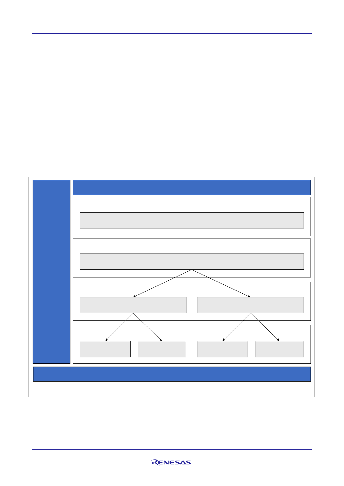
1. I²C Framework Module Features
• ThreadX-aware framework
• Handles integration and synchronization of multiple I²C peripherals on the I²C bus
• Provides a single interface to access both SCI I²C and RIIC drivers
• The I²C framework module configures I²C communication in master mode
• The I²C framework module supports three data rates: 100 k Hz, 400 kHz, and 1 MHz
• The I²C framework module supports both 7-bit addressing and 10-bit addressing
• The I²C framework module also provides support for callbacks internally. User defined callback is not
used. The callback functions are called with the following events i2c_event_t:
Transfer aborted
Transmit complete
Receive complete.
The callback structure i2c_callback_args_t also provides the number of bytes that were sent or
received
Implemented by:
Simple I²C on SCI
RIIC.
Figure 1. I²C Framework Module Block Diagram
R11AN0098EU0102 Rev.1.02 Page 2 of 27
Jan.07.19
Page 3
Renesas Synergy™ Platform I²C Framework Module Guide
Function Name
Example API Call and Definition
open
g_sf_i2c_device.p_api->open (g_sf_i2c_device.p_ctrl,
Opens a designated I²C device on the bus.
close
g_sf_i2c_device.p_api->close (g_sf_i2c_device.p_ctrl);
used by the bus if no devices are connected to the bus.
read
g_sf_i2c_device.p_api->read (g_sf_i2c_device.p_ctrl,
Receives data from I²C device.
write
g_sf_i2c_device.p_api->write (g_sf_i2c_device.p_ctrl, &source,
Transmits data to I²C device.
lock
g_sf_i2c_device.p_api->lock (g_sf_i2c_device.p_ctrl);
several reads and writes without interrupt.
unlock
g_sf_i2c_device.p_api->unlock (g_sf_i2c_device.p_ctrl);
Unlocks the bus from a particular device and makes it available for other devices.
reset
g_sf_i2c_device.p_api->reset (g_sf_i2c_device.p_ctrl, timeout);
Aborts any in-progress transfer and forces the I²C peripheral into ready state.
versionGet
g_sf_i2c_device.p_api->version(version);
Retrieves the version information using the version pointer.
lockWait
g_sf_i2c_device.p_api->lockWait(g_sf_i2c_device.p_ctrl,
Name
Description
SSP_SUCCESS
I²C function performed successfully
SSP_ERR_INVALID_MODE
Illegal I²C mode is specified
SSP_ERR_IP_CHANNEL_NOT_PRESENT
Omitted I²C channel is specified
SSP_ERR_IN_USE
I²C channel has already been opened
SSP_ERR_INVALID_ARGUMENT
Argument is not one of the predefined values
SSP_ERR_INTERNAL
Internal error has occurred
SSP_ERR_ASSERTION
A critical assertion has failed, or Null pointer(s) is(are) given
SSP_ERR_NOT_OPEN
Device instance not opened
SSP_ERR_TRANSFER_ABORTED
The data transfer was aborted
SSP_ERR_INVALID_RATE
The requested rate cannot be set
SSP_ERR_TIMEOUT
Timeout error occurs
2. I²C Framework Module APIs Overview
The I²C Framework interface defines APIs for opening, closing, reading, writing, locking, unlocking, and
resetting the bus using the I²C Framework. A com plete list of the available APIs, an example API call and a
short description of each can be found in the following table. A table of status return values follows the A P I
summary table.
Table 1. I²C Framework Module API Summary
g_sf_i2c_device.p_cfg)
Disables the I²C device designated by control handle. Closes the RTOS services
&destination, no_of_bytes_to_read, restart, timeout);
no_of_bytes_to_write, restart, timeout);
Locks the bus for a device. Locking the bus reserves it until unlocking and allows
timeout);
Locks the bus for a device. Locking the bus reserves it until unlocking and allows
several reads and writes without intervention f rom ot her devices on the same I
Timeout value is user configurable.
Note: For more complete descriptions of operation and definitions for the function data structures, typedefs,
defines, API data, API structures, and function variables, review the SSP User’s Manual API
References for the associated module.
Table 2. Status Return Values
2
C bus.
Note: Lower-level drivers may return common er ror codes. Refer to the SSP User’s Manual API References
for the associated module for a definition of all relev ant status return values.
R11AN0098EU0102 Rev.1.02 Page 3 of 27
Jan.07.19
Page 4

Renesas Synergy™ Platform I²C Framework Module Guide
3. I²C Framework Module Operational Overview
The I²C Framework module complies with the lay ered driver architecture of the SSP. It uses the lower-level
I²C HAL modules to communicate with the I²C peripherals and controls the I²C-capable peripheral s on a
Synergy microcontroller, as configured by a user. With the I²C Framework module, one or more I² C buses
can be created and multiple I²C peripherals can be connected to each I²C bus. The I²C Framework module
APIs use a ThreadX-mutex to acquire and release t he shared bus for I²C slave devices. In the I²C
Framework module, acquire and release are implem ented by lock (or lockWait) and unlock APIs,
respectively.
As the I²C framework module configures I²C comm unication in master mode, this allows the user to:
• Initialize the driver
• Read from a slave device
• Write to a slave device
• Reset the I²C peripheral
• Lock the I²C bus
• Unlock the I²C bus.
The I²C Framework module works with the Synergy MCU I²C hardware modules, the RIIC and SCI HAL
modules. Both I²C modules support the I²C fast-mode with bit rates of up to 400 kHz. The IIC peripheral and
the RIIC HAL module support fast-mode plus with 1-MHz bit-rates. The module supports only master mode
for both implementations.
Multiple Slave Devices on the Same Bus
The I²C Framework module uses a bus and device on bus architecture. If multiple salves are connected t o
the I²C bus, each slave communicates with an ass ociated and separate SF_I2C module instance. Each
SF_I2C instance is created in a separate thread. Every slave device is linked to the bus to which it will be
connected and share the bus with all other slave devices. The user must configure the framework share dbus and the lower-level I²C HAL layer for each framework device connecting to the bus. The user can add
the existing framework shared-bus when configuring multiple devices on the same bus. A common start and
stop procedure is used for all I²C data-transfer operations. Only one device is configured to the lower level
and the remaining devices perform read or write operations by switching the device address within t he
framework.
All I²C Framework devices on the same bus must use the same lower-level con fi guration sett ings (for
example, the I²C HAL module), except for the slave address and addressing mode. The framework uses the
configuration of the first device that it opens in the a pplication to configure the bus. This means that al l I²C
Framework devices on the same bus must have the same lower-level configuration settings (except for the
slave address and addressing mode). If different configurations are used, proper operation cannot be
guaranteed.
Bus Locking
The I²C Framework supports bus-locking funct ional i ty, meaning that the bus can be locked for a given
peripheral. The locking allows devices to reserve a bus to themselves for a given time period (between loc k
and unlock). This allows devices to complete sev eral reads and writes on the bus without interrupti on (which
is required in some instances).
The I²C bus is locked when lock or lockWait APIs are call ed. This API locks the I²C bus by acquiring the
mutex for the thread in which the I²C Framework device is used. Once locked, the I²C bus can only be
utilized by the associated device. The other I²C Framework device, or same I
2
C framework device from othe r
threads, cannot acquire the mutex, so they won’t be able to access the bus. Once the bus is unlocked by
calling the unlock API from the sf_i2c device that l ocked it, the mutex is released and the bus becomes
available for other sf_i2c devices. The lockWait and lock API are similar, except the lock API provides the
2
user with an option to set timeout value. The lockWait API waits for the specified timeout period if the I
is already locked by another device. In case of the lock API, the thread waits forever, if the I
2
C bus is not
C bus
released by the other device.
R11AN0098EU0102 Rev.1.02 Page 4 of 27
Jan.07.19
Page 5

Renesas Synergy™ Platform I²C Framework Module Guide
Resource
ISDE Tab
Stacks Selection Sequence
g_sf_i2c_device0 I2C
Threads
New Stack> Framework> Con ne cti v it y > I²C Framework
3.1 I²C Framework Module Important Operational Notes and Limitations
3.1.1 I²C Framework Module Operational Notes
• The closest possible baud rate that can be achieved (less than or e qual t o t he requested rate) at the
current PCLKB settings is calculated and used. If a valid clock rate could not be calculated, an error is
returned.
• The I²C can trigger the start of other peripherals available from the ELC. See the ELC Module Guide for
further information.
• The I²C Framework can support multiple I²C devices on the same bus if the clock rate remains the same
for all the devices. That means multiple devices can b e opened in the same bus if they are of the same
clock rate. If devices have different clock rates, only one device can be opened at a time.
• SDA and SCL output pin type should be n-channel open drain wh en using I²C on SCI.
• Shared bus can be used by multiple slave devices with the respective configuration. The framework also
handles mutual exclusion in lock and unlock API s when multiple devices are using the same I²C channel.
• To configure multiple I²C devices on the same bus, add and configure the following modules for each
device to be connected to the bus:
I²C Framework device module
Configure the I²C shared bus module for the first dev ice being configured, then use the same bus for
the remaining devices
I²C HAL module
DTC module (optional)
• Lock functionality will be effective for devices from different t hreads. If multiple devices connected to the
bus are from the same thread, the I²C bus will be lock ed for all devices from that thread. In such case s,
even if the bus is locked, all devices from the same t hread can access the bus.
• In case a device is being used from multiple threads, and the dev ice locks the I²C bus from one thread,
the same device cannot access the I²C bus from other threads.
Note: Configure each I²C Framework device with a unique name in the ISDE configurator. Provide the same
configuration settings for devices connected on the same bus (except the slave address and
addressing modes).
3.1.2 I²C Framework Module Limitations
The I²C framework module does not currently support the use of DMA. Refer to the latest SSP Release Notes for any
additional operational limitations for this module.
4. Including the I²C Framework Module in an Application
This section describes how to include the I²C Framewor k module in an application using the SSP
configurator.
Note: It is assumed you are familiar with creating a project, adding threads, adding a stack to a thread, and
configuring a block within the stack. If you are unfami l i ar wit h any of these items, refer to the first few
chapters of the SSP User’s Manual to learn how to manage each of these important steps in creating
To add the I²C Framework module to an application, simply add it to a thread using the stacks selection
sequence given in the following table. (The default name for the I²C Framework Module is
g_sf_i2c_device0. This name can be changed in the associated Properties window.)
Table 3. I²C Framework Module Selection Sequence
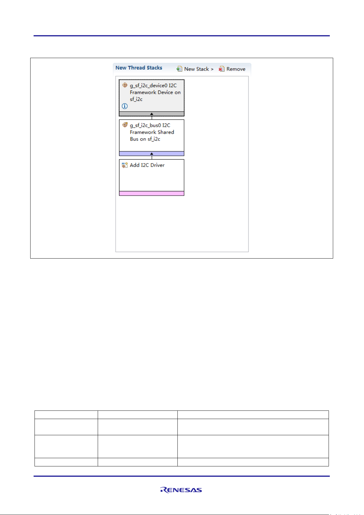
The following figure shows when the I²C Framewo rk m odul e on sf_i2c is added to the thread stack, the
configurator automatically adds any needed low er-level modules. Any drivers that need additional
configuration information are box text highlighted in Red. Modules with a Gray band are individual modules
SSP-based applications.
Framework on sf_i2c
Device on sf_i2c
R11AN0098EU0102 Rev.1.02 Page 5 of 27
Jan.07.19
Page 6
Renesas Synergy™ Platform I²C Framework Module Guide
Parameter
Value
Description
Parameter Checking
BSP, Enabled, Disabled
(Default: Enabled)
Enable or disable parameter error checking.
Name
g_sf_i2c_device0
Give a name to identify the I²C Framework device.
based on this name.
Slave Address
0x00
Specify the address of the I²C slave device.
that stand alone. Modules with a Blue band are sh ared or common and need only be added once and can be
used by multiple stacks.
Figure 2. I²C Framework Module Stack
5. Configuring the I²C Framework Module
The I²C Framework module must be configured by y ou for the desired operation. The SSP configuration
window automatically identifies (by highlighting the block in red) any required configurat i on selections, such
as interrupts or operating modes, which must be configured for lower-level modules for successful operation.
Only those properties that can be changed without causing conflicts are available for modificat ion. Other
properties are ‘locked’ and unavailable for chang es. They are identified with a lock icon for the ‘locked’
property in the Properties window in the ISDE. Thi s appro ach simplifies the configuration process and mak es
it much less error-prone than previous ‘manual’ approaches to configuration. The available configuration
settings and defaults for all the user-accessible properties are given in the Properties tab within the S SP
configurator and are shown in the following table s f or easy ref erence.
Note: You may want to open your ISDE, create the module, and explore the property settings in parallel
with reviewing the following configuration table settings. This help to orient you and can be a useful
hands-on approach to learning the ins and outs of developing with SSP.
Table 4. Configuration Settings for the I²C Frame work Module Device on sf_i2c
R11AN0098EU0102 Rev.1.02 Page 6 of 27
Jan.07.19
API, Config and Control instances will be created
Page 7
Renesas Synergy™ Platform I²C Framework Module Guide
Parameter
Value
Description
Address Mode
7-Bit, 10-Bit
(Default: 7-Bit)
Select the I²C address mode.
ISDE Property
Value
Description
Name
g_sf_i2c_bus0
Module name.
ISDE Property
Value
Description
Parameter Checking
BSP, Enabled, Disabled
(Default: BSP)
Enable or disable parameter error
Name
g_i2c0
Module name.
Channel
0
Specify the SCI channel to be used with
this configuration.
Rate
Standard, Fast-mode
(Default: Standard)
Select the I²C data rate.
Slave Address
0
Address of the slave device.
Address Mode
7-Bit, 10-Bit
(Default: 7-Bit)
Only 7-bit addresses are currently
SDA Output Delay
(nano seconds)
300
SDA output delay in nanoseconds.
Bit Rate Modulation
Enable, Disable
(Default: Enable)
Enables bitrate modulation function.
Callback
NULL
A user callback function can be registered
system.
Receive Interrupt
Priority 0 (highest), Priority 1:14,
(Default: Priority 12)
Receive interrupt priority selection.
Note: The example values and defaults are for a project using the Synergy S7G2 MCU. Other MCUs may
In some cases, settings other than the defaults for lower-level modules can be desirable. For example, i t
might be useful to select different address mode or set different slave address. The configurable properties
for the lower-level modules are given in the following s ecti ons for completeness and as a reference.
Note: Most of the property settings for lower-level modules are intuitive and can usually be determined by
have different default values and available configuration settings.
inspection of the associated Properties window with the SSP configurator.
5.1 Configuration Settings for the I²C Framework Lower-Level Modules
Typically, only a small number of settings must be modified from the default for lower-level dri vers as
indicated by the red text in the thread stack block. Notice that some of the configuration properti es must be
set to a certain value for proper framework operati on and will be locked to prevent user modification. The
following table identifies all the settings within the pr operties section for the module:
Table 5. Configuration Settings for the I²C Framework Shared Bus on sf_i2c
Note: The example values and defaults are for a project using the Synergy S7G2 MCU. Other MCUs may
Table 6. Configuration Settings for the I²C Master Driver on r_sci_i2c
have different default values and available confi guration settings.
Enable
checking.
supported.
in i2c_api_master_t::open. If this callback
function is provided, it will be called from
the interrupt service routine (ISR) for each
of the conditions defined in i2c_event_t.
Warning: Since the callback is called from
an ISR, do not use blocking calls or lengthy
processing. Spending excessive time in an
ISR can affect the responsiveness of the
Priority
R11AN0098EU0102 Rev.1.02 Page 7 of 27
Jan.07.19
Priority 15 (lowest - not valid if
using ThreadX)
Page 8

Renesas Synergy™ Platform I²C Framework Module Guide
ISDE Property
Value
Description
Transmit Interrupt
Priority 0 (highest), Priority 1:14,
(Default: Priority 12)
Transmit interrupt priority selection.
Transmit End Interrupt
Priority 0 (highest), Priority 1:14,
Transmit end interrupt priority selection.
ISDE Property
Value
Description
Parameter Checking
BSP, Enabled, Disabled
(Default: BSP)
Enable or disable parameter error
Name
g_i2c0
Module name
Channel
0
Specify the IIC channel to be used with
this configuration.
Rate
Standard, Fast-mode, Fast-mode plus
Standard, Fast and Fast-plus. (See IIC
Slave Address
0
Set the address of the slave device the
I²C master will be communicating with.
Address Mode
7-Bit, 10-Bit
Only 7-bit addresses are currently
Timeout Mode
Short Mode, Long Mode
(Default: Short Mode)
Select the timeout mode.
Callback
NULL
A user callback function can be
Receive Interrupt
Priority 0 (highest), Priority 1:14,
(Default: Priority 12)
Receive interrupt priority selection
Transmit Interrupt
Priority 0 (highest), Priority 1:14,
Transmit interrupt priority selection
Transmit End Interrupt
Priority 0 (highest), Priority 1:14,
(Default: Priority 12)
Transmit end interrupt priority selection
Error Interrupt Priority
Priority 0 (highest), Priority 1:14,
Error interrupt priority selection
Priority
Priority
Note: The example values and defaults are for a project using the Synergy S7G2 MCU. Other MCUs may
have different default values and available configuration settings.
Table 7. Configuration Settings for the I²C Master Driver on r_riic
Priority 15 (lowest - not valid if
using ThreadX)
Priority 15 (lowest - not valid if
using ThreadX)
(Default: Priority 12)
Default: Standard
(Default: 7-Bit)
checking
Rate Calculation.)
supported.
Priority
Priority
Priority
registered in i2c_api_master_t::open. If
this callback function is provided, it will
be called from the interrupt service
routine (ISR) for each of the conditions
defined in i2c_event_t.
Warning: Since the callback is called
from an ISR, do not use blocking calls
or lengthy processing. Spending
excessive time in an ISR can affect the
responsiveness of the system.
Priority 15 (lowest - not valid if using
ThreadX)
Priority 15 (lowest - not valid if using
ThreadX)
(Default: Priority 12)
Priority 15 (lowest - not valid if using
ThreadX)
Priority 15 (lowest - not valid if using
ThreadX)
(Default: Priority 12)
R11AN0098EU0102 Rev.1.02 Page 8 of 27
Jan.07.19
Page 9
Renesas Synergy™ Platform I²C Framework Module Guide
ISDE Property
Value
Description
Parameter Checking
BSP, Enabled, Disabled
(Default: BSP)
Selects if code for parameter checking
Software Start
Enabled, Disabled
Software start selection.
Linker section to keep
DTC vector table
.ssp_dtc_vector_table
Linker section to keep DTC vector
table.
Name
g_transfer0
Module name
Mode
Normal
Mode selection
Transfer Size
1 Byte
Transfer size selection
Destination Address
Mode
Fixed
Destination address mode selection
Source Address Mode
Incremented
Source address mode selection
Repeat Area (Unused
in Normal Mode
Source
Repeat area selection
Interrupt Frequency
After all transfers have completed
Interrupt frequency selection
Destination Pointer
NULL
Destination pointer selection
Source Pointer
NULL
Source pointer selection
Number of Transfers
0
Number of transfers selection
Number of Blocks
0
Number of blocks selection
Activation Source
(Must enable IRQ)
Event SCI0 TXI
Activation source selection
Auto Enable
FALSE
Auto enable selection
Callback (Only valid
with Software start)
NULL
Callback selection
ELC Software Event
Priority 0 (highest), Priority 1:14,
ELC software event interrupt priority
ISDE Property
Value
Description
Parameter Checking
BSP, Enabled, Disabled
(Default: BSP)
Selects if code for parameter checking
Software Start
Enabled, Disabled
Software start selection
Linker section to keep
DTC vector table
.ssp_dtc_vector_table
Linker section to keep DTC vector
table.
Name
g_transfer1
Module name
Mode
Normal
Mode selection
Transfer Size
1 Byte
Transfer size selection
Destination Address
Mode
Incremented
Destination address mode selection
Source Address Mode
Fixed
Source address mode selection
Repeat Area (Unused
in Normal Mode
Destination
Repeat area selection
Note: The example values and defaults are for a project using the Synergy S7G2 MCU. Other MCUs may
have different default values and available configuration settings.
Table 8. Configuration Settings for the Transfer Driver on r_dtc Event SCI0 TXI
is to be included in the build
(Default: Disabled)
(Valid only in Block
Mode)
Interrupt Priority
Note: The example values and defaults are for a project using the Synergy S7G2 MCU. Other MCUs may
have different default values and available configuration settings.
Table 9. Configuration Settings for the Transfer Driver on r_dtc Event SCI0 RXI
Priority 15 (lowest - not valid if using
ThreadX), Disabled
(Default: Disabled)
(Default: Disabled)
selection.
is to be included in the build
R11AN0098EU0102 Rev.1.02 Page 9 of 27
Jan.07.19
Page 10

Renesas Synergy™ Platform I²C Framework Module Guide
ISDE Property
Value
Description
Interrupt Frequency
After all transfers have completed
Interrupt frequency selection
Destination Pointer
NULL
Destination pointer selection
Source Pointer
NULL
Source pointer selection
Number of Transfers
0
Number of transfers selection
Number of Blocks
Mode)
0
Number of blocks selection
Activation Source
Event SCI0 RXI
Activation source selection
Auto Enable
FALSE
Auto enable selection
Callback (Only valid
NULL
Callback selection
ELC Software Event
Priority 0 (highest), Priority 1:14,
(Default: Disabled)
ELC software event interrupt priority
ISDE Property
Value
Description
Parameter Checking
BSP, Enabled, Disabled
Selects if code for parameter checking
Software Start
Enabled, Disabled
(Default: Disabled)
Software start selection
Linker section to keep
.ssp_dtc_vector_table
Linker section to keep DTC vector
Name
g_transfer0
Module name
Mode
Normal
Mode selection
Transfer Size
1 Byte
Transfer size selection
Destination Address
Fixed
Destination address mode selection
Source Address Mode
Incremented
Source address mode selection
Repeat Area (Unused
Source
Repeat area selection
Interrupt Frequency
After all transfers have completed
Interrupt frequency selection
Destination Pointer
NULL
Destination pointer selection
Source Pointer
NULL
Source pointer selection
Number of Transfers
0
Number of transfers selection
Number of Blocks
Mode)
0
Number of blocks selection
Activation Source
Event IIC0 TXI
Activation source selection
Auto Enable
FALSE
Auto enable selection
Callback (Only valid
NULL
Callback selection
ELC Software Event
Priority 0 (highest), Priority 1:14,
(Default: Disabled)
ELC software event interrupt priority
(Valid only in Block
(Must enable IRQ)
with Software start)
Interrupt Priority
Note: The example values and defaults are for a project using the Synergy S7G2 MCU. Other MCUs may
have different default values and available configuration settings.
Table 10. Configuration Settings for the Transfer Driver on r_dtc Event IIC0 TXI
DTC vector table
Mode
in Normal Mode
Priority 15 (lowest - not valid if using
ThreadX), Disabled
(Default: BSP)
selection
is to be included in the build
table
(Valid only in Block
(Must enable IRQ)
with Software start)
Interrupt Priority
R11AN0098EU0102 Rev.1.02 Page 10 of 27
Jan.07.19
Priority 15 (lowest - not valid if using
ThreadX), Disabled
selection
Page 11

Renesas Synergy™ Platform I²C Framework Module Guide
ISDE Property
Value
Description
Parameter Checking
BSP, Enabled, Disabled
Default: BSP
Selects if code for parameter checking
Software Start
Enabled, Disabled
Software start selection.
Linker section to keep
DTC vector table
.ssp_dtc_vector_table
Linker section to keep DTC vector
table.
Name
g_transfer1
Module name
Mode
Normal
Mode selection
Transfer Size
1 Byte
Transfer size selection
Destination Address
Mode
Incremented
Destination address mode selection
Source Address Mode
Fixed
Source address mode selection
Repeat Area (Unused
in Normal Mode
Destination
Repeat area selection
Interrupt Frequency
After all transfers have completed
Interrupt frequency selection
Destination Pointer
NULL
Destination pointer selection
Source Pointer
NULL
Source pointer selection
Number of Transfers
0
Number of transfers selection
Number of Blocks
0
Number of blocks selection
Activation Source
(Must enable IRQ)
Event IIC0 RXI
Activation source selection
Auto Enable
FALSE
Auto enable selection
Callback (Only valid
with Software start)
NULL
Callback selection
ELC Software Event
Priority 0 (highest), Priority 1:14,
ELC software event interrupt priority
Table 11. Configuration Settings for the Transfer Driver on r_dtc Event IIC0 RXI
is to be included in the build
Default: Disabled
(Valid only in Block
Mode)
Interrupt Priority
Note: The example values and defaults are for a project using the Synergy S7G2 MCU. Other MCUs may
have different default values and available configuration settings.
Priority 15 (lowest - not valid if using
ThreadX), Disabled
(Default: Disabled)
selection.
5.2 I²C Framework Module Clock Configuration
The SCI peripheral module uses PCLKB as its clock source. The PCLKB frequency is set using the SSP
configurator clock tab prior to a build or by using the C GC I nterface at run-time. During configuration, the I²C
transfer rate is calculated and set internally by the driver, based on the user-selected PCLKB rat e and the
user-selected transfer rate. If the PCLKB is configured in suc h a m anner that the user-selected rate cannot
be achieved, an error is returned when initializing t he driver.
R11AN0098EU0102 Rev.1.02 Page 11 of 27
Jan.07.19
Page 12

Renesas Synergy™ Platform I²C Framework Module Guide
Resource
ISDE Tab
Pin Selection Sequence
SCI
Pins
Select Peripherals > Connectivity: SCI > SCI0
Pin Configuration
Property
Value
Description
Pin Group Selection
Mixed, _A only, _B only
(Default: Mixed)
Pin group selection
Operation Mode
Disabled, Custom, Asynchronous
(Default: Simple SPI)
Select Simple I²C as the Operation
SDA
None, P411, P101 (Default: None)
SDA Pin
SCL
None, P410, P100 (Default: None)
SCL Pin
Resource
ISDE Tab
Pin Selection Sequence
IIC
Pins
Select Peripherals > Connectivity: IIC > IIC1
Pin Configuration Property
Value
Description
Pin Group Selection
Mixed, _A only, _B only
(Default: _A only)
Pin group selection
Operation Mode
Disabled, Enabled
(Default: Disabled)
Select operation mode
SDA
None, P206, P101 (Default: None)
SDA Pin
SCL
None, P205, P100 (Default: None)
SCL Pin
5.3 I²C Framework Module Pin Configuration
The SCI and I²C peripheral module uses pins on the M CU to communicate to external devices. I/O pins m ust
be selected and configured as required by the external device. The following table illustrates the met hod for
selecting the pins within the SSP configuration window and the subsequent table illustrates an ex am ple
selection for the pins.
Note: For some peripherals, the operation-mode selection determines what peripheral signal s are available
and what MCU pins are required.
Table 12. Pin Selection Sequence for SCI0
Note: The selection sequence assumes SCI0 is the desired hardware target for the driver.
Table 13. Pin Configuration Settings for the I²C Framework Module on SCI
UART, Simple SPI, Simple I²C,
Synchronous UART, Smart Card
Note: The example values are for a project using the Synergy S7G2 MCU and the SK-S7G2 Kit. Other
Synergy Kits and other Synergy MCUs may have dif ferent available pin configuration settings.
Table 14. Pin Selection Sequence for IIC1
Note: The selection sequence assumes IIC1 is the desired hardware target for the driver.
Table 15. Pin Configuration Settings for the I²C Framework Module on IIC
Mode for I²C on SCI
Note: The example values are for a project using the Synergy S7G2 MCU and the SK-S7G2 Kit. Other
Synergy Kits and other Synergy MCUs may have dif ferent available pin configuration settings.
R11AN0098EU0102 Rev.1.02 Page 12 of 27
Jan.07.19
Page 13

Renesas Synergy™ Platform I²C Framework Module Guide
5.4 I²C Framework Module Other Settings
In addition to the SCL and SDA pins, an I²C RESET signal may be required to reset the I²C slave device. If
this is the case, the RESET signal can be added using a G P IO pin and must be controlled directly by the
application program. The external device reset f unct ion is not supported within the r_sci_i2c or r_iic
module.
6. Using the I²C Framework Module in an Application
A common application for the I²C framework module requires multiple slave devices on a single bus. The
implementation for this common application is de scribed below. (For an application where multiple bus ses
are required, just duplicate the single bus example as needed for each separate bus.)
6.1 Implementation Steps for Two Slave Devices on the Same Shared Bus
When using the I²C framework module to create a si ngl e bus with multiple slave devices create two thread
stacks each with an I²C framewor k instances. These instances each use the same share d bus instance and
the following steps instruct you in how to do this within the SSP Configurator.
Notes:
1. The following example puts both sf_i2c module inst ances in the same thread. If the bus locking
function is needed, the sf_i2c modules should be put i n di f ferent threads. Locking applies to all the
devices within the locked thread.
2. The following steps assume some familiarity with the use of the SSP development environment. If
any of the following steps are confusing, read over t he first few chapters of the SSP User’s Manual
to become familiar with the SSP development environment.
3. Add the first I²C framework device to a new or existing thread. This creates the I²C master stack. A
shared bus on sf_i2c is added along with the I²C driver. The I²C driv er can be selected for
implementation on r_riic or r_sci_i2c. The DTC transfer driver is also added by default. This can be
removed if the CPU transfer mode is needed instea d.
The resulting module stack is shown in the following figure. Example configuration settings are given in t he
tables that follow the figure:
Figure 3. Example module stack — both sf_i2c modu le instances in the same thread
The following table lists an example configuration setting for the first thread and thread stack.
R11AN0098EU0102 Rev.1.02 Page 13 of 27
Jan.07.19
Page 14

Renesas Synergy™ Platform I²C Framework Module Guide
Property
Value
Description
Parameter Checking
Default (BSP)
Enable or Disable Parameter Checking.
Name
g_sf_i2c_device0
Give a name to identify the I²C Framework device. API, Config
Slave Address
0x48
Specify the address of I²C slave 1.
Address Mode
7-bit
Select the I²C address mode.
Property
Value
Description
Name
g_sf_i2c_bus0
Give a name to identify the I²C Framework shared bus . This shared bus is
Property
Value
Description
Parameter Checking
Default (BSP)
Enable or Disable Parameter Checking.
Name
g_i2c0
Give a name to identify the I²C Driver device. This will be
used internally by Framework.
Channel
0
Specify the I²C channel.
Rate
Standard
Select the speed of the I²C bus.
Slave Address
0
This field will be locked as slave address already configured
Address Mode
7-bit
This field will be locked as address mode already configured
in the I²C Framework Device on sf_i2c.
Timeout Mode
Short Mode
Select Timeout mode: Short mode or Long mode
Callback
NULL
This field will be locked as Framework does not prov ide
callback handling to the user.
Receive Interrupt Priority
Priority 2
Receive interrupt priority selection.
Transmit Interrupt Priority
Priority 2
Transmit interrupt priority selection.
Transmit End Interrupt
Priority 2
Transmit end interrupt priority selection.
Error Interrupt Priority
Priority 2
Error interrupt priority selection.
Property
Value
Description
Parameter
Checking
Default(BSP)
Enable Or Disable Parameter Checking.
Name
g_i2c0
Give a name to identify the I²C Driver device. This will be used by
Channel
0
Specify the address of I²C slave.
Rate
Standard
Select the speed of the I²C bus.
Slave Address
0
This field will be locked as slave address already configured in the
I²C Framework Device on sf_i2c.
Address Mode
7-bit
This field will be locked as address mode already configured in the
Slave Output Delay
300
SDA output delay in nanoseconds.
Bit Rate Modulation
Enable
Enables bitrate modulation function.
Callback
NULL
This field will be locked as Framework does not provide callback
handling to the user.
Table 16. Special Configuration Settings for Example Thread 1 (Slave #1)
and Control instances will be created based on this name.
Table 17. Configuration Settings for the I²C Framework Shared Bus on sf_i2c
shared by multiple I²C Framework Devices.
Table 18. Configuration Settings for the I²C Master Driver on r_riic
in the I²C Framework Device on sf_i2c.
Priority
Table 19. Configuration Settings for the I²C Master Driver on r_sci_i2c
Framework internally.
I²C Framework Device on sf_i2c.
Enable
R11AN0098EU0102 Rev.1.02 Page 14 of 27
Jan.07.19
Page 15

Renesas Synergy™ Platform I²C Framework Module Guide
Property
Value
Description
Receive Interrupt
Priority
Priority 2
Receive interrupt priority selection.
Transmit Interrupt
Priority 2
Transmit interrupt priority selection.
Transmit End
Interrupt Priority
Priority 2
Transmit end interrupt priority selection.
Property
Value
Description
Parameter Checking
Default (BSP)
Enable Or Disable Parameter Checking.
Software Start
Disabled
Linker section to keep
DTC vector table
.ssp_dtc_vector_table
Linker section to keep DTC vector table.
Name
g_transfer0
Module name.
Mode
Normal
Mode selection. This field is locked.
Transfer Size
1 Byte
Transfer size selection. This field is locked.
Destination Address
Mode
Fixed
Destination address mode selection. This field is
locked.
Source Address Mode
Incremented
Source address mode selection. This field is locked.
Repeat Area (Unused in
Normal Mode
Source
Repeat area selection. This field is locked.
Interrupt Frequency
After all transfers
This field is locked.
Destination Pointer
NULL
Destination pointer selection. This field is locked.
Source Pointer
NULL
Source pointer selection. This field is locked.
Number of Transfers
0
Number of transfer selection. This field is locked.
Number of Blocks (Valid
0
Number of blocks selection. This field is locked.
Activation Source (Must
enable IRQ)
Event IIC0 TXI
Activation source selection. This field is locked.
Auto Enable
False
Auto enable selection. This field is locked.
Callback (Only valid with
Software start)
NULL
Callback selection. This field is locked.
ELC Software Event
Disabled
ELC software event interrupt priority selection.
Property
Value
Description
Parameter Checking
Default(BSP)
Enable or Disable Parameter Checking.
Software Start
Disabled
Software Start Selection.
Linker section to keep
.ssp_dtc_vector_table
Linker section to keep DTC vector table.
Name
g_transfer0
Module name.
Mode
Normal
Mode selection. This field is locked.
Transfer Size
1 Byte
Transfer size selection. This field is locked.
Destination Address
Incremented
Destination address mode selection. This field is
Source Address Mode
Fixed
Source address mode selection. This field is locked.
Repeat Area (Unused
Destination
Repeat area selection. This field is locked.
Priority
Table 20. Configuration Settings for the Transfer Driver on r_dtc Event IIC0 TXI
have completed
only in Block Mode)
Interrupt Priority
Table 21. Configuration Settings for the Transfer Driver on r_dtc Event IIC0 RXI
DTC vector table
Mode
in Normal Mode
R11AN0098EU0102 Rev.1.02 Page 15 of 27
Jan.07.19
locked.
Page 16

Renesas Synergy™ Platform I²C Framework Module Guide
Property
Value
Description
Interrupt Frequency
After all transfers have
completed
This field is locked.
Destination Pointer
NULL
Destination pointer selection. This field is locked.
Source Pointer
NULL
Source pointer selection. This field is locked.
Number of Transfers
0
Number of transfer selection. This field is locked.
Number of Blocks
Mode)
0
Number of blocks selection. This field is locked.
Activation Source (Must
Event IIC0 RXI
Activation source selection. This field is locked.
Auto Enable
False
Auto enable selection. This field is locked.
Callback (Only valid
NULL
Callback selection. This field is locked.
ELC Software Event
Interrupt Priority
Disabled
ELC software event interrupt priority selection.
Property
Value
Description
Parameter Checking
Default(BSP)
Enable Or Disable Parameter Checking
Name
g_sf_i2c_devi
ce1
Give a name to identify the I2C Framework device. API, Config and
Control instances will be created based on this name.
Slave Address
0x28
Specify the address of I²C slave2
Address Mode
7-bit
Select the I²C address mode.
(Valid only in Block
enable IRQ)
with Software start)
Add the second I²C Framework Device to the second t hread. The I²C Framework Shared Bus on sf_i2c is not
added automatically. Select the option to use the exi sting shared bus. The Configurator then automatically
adds the I²C Framework Shared Bus on sf_i2c and remaining modules. The lower level modules are added
and configured automatically to be consistent with the previously defined settings from the first I²C framework
instance. In fact, if any lower level settings are chang ed in on st ack, they are automatically updated in the
other.
The resulting module stack is shown in the following figure:
Figure 4. Example module stack — Second I²C Framework Device on second thread
The following table lists the example configuration setting for the second thread and thread stack.
Table 22. Special Configuration Settings for Example Thread 2 (Slave #2)
R11AN0098EU0102 Rev.1.02 Page 16 of 27
Jan.07.19
Page 17

Renesas Synergy™ Platform I²C Framework Module Guide
Notes:
1. The listed configuration settings can be repeated to add more slave devices to the same bus — if they
share the same low-level settings.
2. Because existing shared bus of I²C Fram ework Shared Bus on sf_i2c is used, the setting for lower level
modules is the same as the first thread. No additional settings are needed.
3. If a set of slave devices have different l ower-level settings than another set, they must use a different bus
and can be implemented by repeating the two steps outlined above — defining a different bus and the
different lower-level characteristics for the set of slave devices.
6.2 Adding Another Shared Bus
The I²C framework module which will use a second shared b us can be added to any thread. Starting with the
previous example, if it is added to the I2C_Device1 thread, then the module stack would appear (see figure).
Available options for the shared bus are New or Use.
Figure 5. Example module stack — adding another shared bus
Select New to and add another I²C Framework Shared Bus on sf_i2c module. Configure the shared bus
properties as needed for the application. Select the desired low-level I²C driver. The channel num ber for the
g_i2c1 I²C driver module, must be different from t he channel number for the g_i2c0 I²C driver module. The
following figure shows the resulting thread stac k:
Figure 6. Example thread stack on I²C Framework Shared Bus
R11AN0098EU0102 Rev.1.02 Page 17 of 27
Jan.07.19
Page 18

Renesas Synergy™ Platform I²C Framework Module Guide
A second device can be added in the I2C_Device2 t hread using the same information provided in this
section. The following figure shows t he resulting thread stack:
Figure 7. Example thread stack — adding a second device
6.3 The typical steps in using the Framework module in an application
The typical steps in using the I²C Framework module i n an appl ication are:
1. Initialize the I²C Framework module using the open API. Each I²C framework module needs to call t he
open API at least once before performing any operat i ons on the bus.
2. Reset the I²C MCU perip heral using the reset API — if needed.
3. Lock the bus using the lock or lockWait API for a framework module. Once the bus is locked by an I²C
framework module it cannot be used by any other I²C framework module on the same bus. Locking
ensures ownership of the bus remains with the I²C fram ework module until it is unlocked. Operations
initiated from other I²C framework modules on the bus will fail w hile the bus is locked. It is not mandatory
to lock the bus before any read/write operations on t he bus — locking is optional, if needed. If thread is
not supposed to wait forever when locking the I²C bus, call the lockWait API with desired timeout value.
4. Write data to the slave using the write API. The write operation will not be successful if the bus is already
locked by any other I²C framework module.
5. Read data from the slave using the read API. The read operation will not be successful if the bus is
already locked by any other I²C framework module.
6. Unlock the bus using the unlock API i f it is alre ady locked by the same I²C framework module. Once t he
bus is unlocked, other I²C framework modules can use it. It is necessary to unlock the locked bus afte r
the protected read or write operations are over. (if needed)
7. Close the I²C framework module using the close API. Each I²C framework module can call t he close API
after all its read and write operations on the bus are c om pleted — if needed.
The following diagram illustrates common steps in a typical operat ional flow:
R11AN0098EU0102 Rev.1.02 Page 18 of 27
Jan.07.19
Page 19

Renesas Synergy™ Platform I²C Framework Module Guide
Resource
Revision
Description
Integrated Solution Development
Environment
SSP
v1.5.0
Synergy Software Platform
IAR Embedded Workbench® for Renesas
Synergy™
SSC
v6.2.1
Synergy Standalone Configurator
1. Ini tialize the I2 C Framewor k
.op en
3. Loc k the bus (i f needed)
.lock
4. Wri te data to the sl ave
.wri te
5. Rea d data from the slave
.rea d
6. Unl oc k the bus
.unlock
7. Cl o se th e I2C Fr amework (i f n eeded )
.cl ose
2. Reset the I 2 C MCU p eri ph eral (i f needed)
.reset
7. The I²C Framework Module Application Project
Figure 8. Flow Diagram of a Typical I²C Framework Module Application
The application project associated with this module guide demonstrates a typical example. You may want to
import and open the application project within t he ISDE and view the configuration settings for the I²C
Framework module. You can also read over the code (i n humidity_thread_entry.c and
pressure_thread_entry.c) that is used to illustrate the I²C Framework module APIs in a complete
design.
The application project demonstrates the typical us e of the I²C Framework module APIs. The application
project creates two threads, one is for sampling humidity value from slave device 0, and the other i s t he
sampling pressure value from slave device 1. These two devices use the same low-level layer that consists
of the I²C Framework shared bus and the I²C Master Driver. The di fference between these two devices is
slave address that is set in properties of I²C Framework Device. E ach device access starts with read or write
APIs with particular slave address.
Table 23. Software and Hardware Resources Used by the Application Project
e2 studio v6.2.1
IAR EW for Renesas Synergy v8.23.1
R11AN0098EU0102 Rev.1.02 Page 19 of 27
Jan.07.19
Page 20

Renesas Synergy™ Platform I²C Framework Module Guide
Resource
Revision
Description
SK-S7G2
v3.0, v3.1, v3.3
Starter Kit
Sensor Shield board (ZR-9500-ASY)
REV B
Accessory in PK-Cloud1
Note: The application project assumes that you are familiar with using printf(), semi-hosting, and the Debug
Console in your ISDE. If you are unfamiliar with these techniques, refer to the “How do I Use Printf()
with the Debug Console in the Synergy Software Package” Knowledge Base article given in the
The following figure shows an actual hardware conn ection:
References section at the end of this document.
R11AN0098EU0102 Rev.1.02 Page 20 of 27
Jan.07.19
Figure 9. Hardware connection picture
Page 21

Renesas Synergy™ Platform I²C Framework Module Guide
Pin Configuration Property
Setting
Pin Group Selection
A only
2. I ni tia li ze the I2C Framework
.op en
6. Rea d data from the slave
.rea d
8. Unl ock th e s hared bus
.unlock
Sta rt Th rea d
1. Initialize semi hosting
3. Res et the I2C MCU peri pheral
.res et
4. Lock the sha red bus
.lock
7. Cal cula te a ctual va lue a nd output
5. Send c omma nd to the s l av e
.wri te
9. Sl eep f or 1 s
1. I ni tia li ze the I2C Framework
.op en
6. Rea d data from the slave
.rea d
8. Unl ock th e s hared bus
.unlock
Sta rt Th rea d
2. Lock the sha red bus
.lock
7. Cal cula te a ctual va lue a nd output
5. Send c omma nd to the s l av e
.wri te
9. Sl eep f or 1 s
3. Send reset command to the slave
.wri te
4. Wait 50ms
Th read 1
Th read 2
Note: Channel 8 I²C signals can also be led out to conne ct with a specified sensor board using the Dupont
The following diagram shows a simple flow dia gram of the application project:
Line.
Figure 10. I²C Framework Module Application Project Flow Diagram
The configuration settings in the application project need to be customized for the specifics of the t arget kit
and MCU. The I²C Framework module in the applic ation project uses the I²C Framework which uses the I²C
shared bus and the I²C master driver as low-level support. I²C master driver is based on the r_sci_i2c
module and uses channel 8 for I²C communication. The output pins for I²C communication are selected t o
conform with the signal connections from the slave device. These are P104 for SCL and P105 for SDA. It
can be helpful to open the application project in the IS DE and l ocate these settings in the Pin configuration
tab. These signals can also be located on the schematic for the SK-S7G2 as a check on the validity of the
selected pins for the I²C signals. The I²C signals on Arduino Shield Uno interface are used to connect wit h an
external sensor shield board which is plugged into. T his external sensor shield board is an accessory of PKCloud1. It can also be replaced with any board customized by the user if the humidi t y and temperature
sensor HIH6030 and barometric pressure sensor MS5637 are designed on the board. The location for the
schematic is provided in the References section at the end of this document.
See section 6.1 for the application project configuration setting of two threads and threads stack. The
following table list port configuration settings for I²C interface:
Table 24. Pin Configuration Settings for SCI channel 8
R11AN0098EU0102 Rev.1.02 Page 21 of 27
Jan.07.19
Page 22

Renesas Synergy™ Platform I²C Framework Module Guide
Pin Configuration Property
Setting
Operation Mode
Simple I2C
SDA
P105
SCL
P104
Once the I²C Framework application project has been successfully added and configured, it can be used by
the application program. The I²C Framework application project implements steps in a similar manne r to
those shown for the general case as described in the preceding chapter. There is a key point of read and
write function that is the restart parameter deciding to send slave address or not.
Refer to the code in humidity_thread_entry.c and pressure_thread_entry.c, as you follow along
with the flow outlined in the previous Project Flow Diagram. The first section of the
humidity_thread_entry.c has the header files which are referred to in the I²C instance structure to
allow semi-hosting support to display results using printf(). The following section calls open and reset
APIs for initializing I²C framework device, then enter an infinite loop for getting raw data from slave device. In
this infinite loop, before using write and read APIs, lock API is called first to prevent t he shared bus from
use of other I²C framework device. Locking successfully leads to use of write and read APIs without
interrupt. After getting raw data, calculat e act ual value and output it on Debug Console using printf().
The second thread has almost the same process of the first thread except call of reset API, because
resetting the I²C MCU peripheral has been done by the first thread.
Note: It is assumed that you are familiar with using printf() and the D ebug Console in the Synergy
Software Package. If you are unfamiliar with this, ref er to the “How do I Use Printf() with the Debug
Console in the Synergy Software Package” Knowle dge Base article, available as described in the
References section at the end of this document. A l ternatively, you can see results using the watch
A few key properties are configured in this application project to support the required operations and the
physical properties of the target board and MC U. T he properties with the values set for this specific p roject
are listed in the following table. You can also open the application project and view these settings in the
Properties window as a hands-on exercise.
variables in the debug mode.
8. Customizing the I²C Framework Module for a Target Application
Some configuration settings are normally changed by the developer from those shown in the a ppl i cation
project. For example, the user can easily change the configuration settings for the SCI clock by updating the
PCLKB in the Clocks tab. The user can also change the slave address in I²C Framework Drive to connect
with other different sensors. Besides, DTC transfer is an optional item for I²C Master Driver, so you can
remove the default option from I²C master driver acco rding to your application.
9. Running the I²C Framework Module Application Project
To run the I²C Framework application project and t o see it executed on a target kit, you can simply import it
into your ISDE, compile, and run debug.
Note: The following steps are sufficiently detailed for someone experienced with the basic flow through the
Synergy development process. If these steps are unfamiliar, refer to the first few chapters of the SSP
To create and run the application project simply f ol l ow t hese steps:
1. Import and build the example project included with this package according to the Renesas Synergy™
2. Plug Sensor Shield board into Arduino interface.
3. Connect to the host PC using the USB cable (use J19 DEBUG_USB connector).
4. Start to debug the application.
5. The output can be viewed in the Renesas Debug Console.
User’s Manual for a description of how to accompl ish these steps.
Project Import Guide (r11an0023eu0121-synergy-ssp-import-guide.pdf).
R11AN0098EU0102 Rev.1.02 Page 22 of 27
Jan.07.19
Page 23

Renesas Synergy™ Platform I²C Framework Module Guide
Figure 11. Example Output from I²C Framework Application Project
Notes:
1. Output value may differ based on environment.
2. The first lock failure (Failed to lock I² C framework of device1) occurs before unlocking the shared bus of
device 0.
3. To output the float value on the Debug Console in e
2
studio, find the project-> properties -> C/C++ Build
-> Settings -> Tool Settings -> Cross ARM C Linker -> Miscellaneous, and check the item “U se f l oat
with nano printf (-u _printf_float)” shown in the f ollow ing figure shows.
4. For output degree centigrade symbol on Terminal I/O in IAR, in debug status, find Tools -> Options ->
Terminal I/O -> Encoding -> Select UTF-8 instead of System which the following figure shows.
R11AN0098EU0102 Rev.1.02 Page 23 of 27
Jan.07.19
Page 24

Renesas Synergy™ Platform I²C Framework Module Guide
Figure 12. Enable the output of float value using printf() in e2 studio
R11AN0098EU0102 Rev.1.02 Page 24 of 27
Jan.07.19
Page 25

Renesas Synergy™ Platform I²C Framework Module Guide
Figure 13. Enable the output of degree centigrade symbol in IAR Terminal I/O
10. I²C Framework Module Conclusion
This module guide has provided all the background information needed to select, add, configure an d use the
module in an example project. Many of these steps w ere t i m e consuming and error-prone activities in
previous generations of embedded systems. T he Renesas Synergy Platform makes these steps much less
time consuming and removes the common errors, like conflicting configuration settings or the incorrect
selection of lower-level modules. The use of high-level APIs (as demonstrated in the application project)
illustrate additional development time savings by al l owing work to begin at a high level, avoiding the time
required in older development environments to use, or in some cases, create, lower-level drivers.
11. I²C Framework Module Next Steps
After you have mastered a simple I²C Framework application project, you may want to review a more
complex example. The GUIX for the SK-S7G2 application example demonstrates the use of the I²C
Framework to implement the touch controller. This project is available through the link shown in the
References section at the end of this document.
12. I²C Framework Module Reference Information
SSP User Manual: Available in html format in the SSP distribution package and as a pdf from the Sy nergy
Gallery.
Links to all the most up-to-date sf_i2c module reference materials and resources are available on the
Synergy Knowledge Base: https://en-
support.renesas.com/search/sf_i2c%20Module%20Guide%20Resources.
R11AN0098EU0102 Rev.1.02 Page 25 of 27
Jan.07.19
Page 26

Renesas Synergy™ Platform I²C Framework Module Guide
Website and Support
Visit the following vanity URLs to learn about key elements of the Synergy Platform, download components
and related documentation, and get support.
Synergy Software www.renesas.com/synergy/software
Synergy Software Package www.renesas.com/synergy/ssp
Software add-ons www.renesas.com/synergy/addons
Software glossary www.renesas.com/synergy/softwareglossary
Development tools www.renesas.com/synergy/tools
Synergy Hardware www.renesas.com/synergy/hardware
Microcontrollers www.renesas.com/synergy/mcus
MCU glossary www.renesas.com/synergy/mcuglossary
Parametric search www.renesas.com/synergy/parametric
Kits www.renesas.com/synergy/kits
Synergy Solutions Gallery www.renesas.com/synergy/solutionsgallery
Partner projects www.renesas.com/synergy/partnerprojects
Application projects www.renesas.com/synergy/applicationprojects
Self-service support resources:
Documentation www.renesas.com/synergy/docs
Knowledgebase www.renesas.com/synergy/knowledgebase
Forums www.renesas.com/synergy/forum
Training www.renesas.com/synergy/training
Videos www.renesas.com/synergy/videos
Chat and web ticket www.renesas.com/synergy/resourcelibrary
R11AN0098EU0102 Rev.1.02 Page 26 of 27
Jan.07.19
Page 27

Renesas Synergy™ Platform I²C Framework Module Guide
Rev.
Date
Description
Page
Summary
1.00
May.15.17
–
Initial Release
1.01
Aug.07.17
16
Update to Hardware and Software Resource table
1.02
Jan.07.19
–
Updated for v1.5.0
Revision History
R11AN0098EU0102 Rev.1.02 Page 27 of 27
Jan.07.19
Page 28

Corporate Headquarters
Contact information
www.renesas.com
Trademarks
of their respective owners.
Notice
1. Descriptions of circuits, software and other related information in this document are provided only to illustrate the operation of semiconductor products
and application examples. You are fully responsible for the incorporation or any other use of the circuits, software, and information in the design of your
product or system. Renesas Electronics disclaims any and all liability for any losses and damages incurred by you or third parties arising from the use
of these circuits, softw a r e, or information.
2. Renesas Electronics hereby expressly disclaims any warranties against and liability for infringement or any other claims involving patents, copyrights,
or other intellectual property rights of third parties, by or arising from the use of Renesas Electronics products or technical information described in this
document, including but not limited to, the product data, drawings, charts, programs, algorithms, and application examples.
3. No license, express, implied or otherwise, is granted hereby under any patents, copyrights or other intellectual property rights of Renesas Electronics
or others.
4. You shall not alter, modify, copy, or reverse engineer any Renesas Electronics product, whether in whole or in part. Renesas Electronics disclaims any
and all liability for any losses or damages incurred by you or third parties arising from such alteration, modification, copying or reverse engineering.
5. Renesas Electronics products are classified according to the following two quality grades: “Standard” and “High Quality”. The intended applications for
each Renesas Electronics product depends on the product’s quality grade, as indicated below.
"Standard": Computers; office equipment; communications equipment; test and measurement equipment; audio and visual equipment; home
"High Quality": Transportation equipment (automobiles, trains, ships, etc.); traffic control (traffic lights); large-scale communication equipment; key
Unless expressly designated as a high reliability product or a product for harsh environments in a Renesas Electronics data sheet or other Renesas
Electronics document, Renesas Electronics products are not intended or authorized for use in products or systems that may pose a direct threat to
human life or bodily injury (artificial life support devices or systems; surgical implantations; etc.), or may cause serious property damage (space
system; undersea repeaters; nuclear power control systems; aircraft control systems; key plant systems; military equipment; etc.). Renesas Electronics
disclaims any and all liability for any damages or losses incurred by you or any third parties arising from the use of any Renesas Electronics product
that is inconsistent with any Renesas Electronics data sheet, user’s manual or other Renesas Electronics document.
6. When using Renesas Electronics products, refer to the latest product information (data sheets, user’s manuals, application notes, “General Notes for
Handling and Using Semiconductor Devices” in the reliability handbook, etc.), and ensure that usage conditions are within the ranges specified by
Renesas Electronics with respect to maximum ratings, operating power supply voltage range, heat dissipation characteristics, installation, etc. Renesas
Electronics disclaims any and all liability for any malfunctions, failure or accident arising out of the use of Renesas Electronics products outside of such
specified ranges.
7. Although Renesas Electronics endeavors to improve the quality and reliability of Renesas Electronics products, semiconductor products have specific
characteristics, such as the occurrence of failure at a certain rate and malfunctions under certain use conditions. Unless designated as a high reliability
product or a product for harsh environments in a Renesas Electronics data sheet or other Renesas Electronics document, Renesas Electronics
products are not subject to radiation resistance design. You are responsible for implementing safety measures to guard against the possibility of bodily
injury, injury or damage caused by fire, and/or danger to the public in the event of a failure or malfunction of Renesas Electronics products, such as
safety design for hardware and software, including but not limited to redundancy, fire control and malfunction prevention, appropriate treatment for
aging degradation or any other appropriate measures. Because the evaluation of microcomputer software alone is very difficult and impractical, you are
responsible for evaluating the safety of the final products or systems manufactured by you.
8. Please contact a Renesas Electronics sales office for details as to environmental matters such as the environmental compatibility of each Renesas
Electronics product. You are responsible for carefully and sufficiently investigating applicable laws and regulations that regulate the incl usion or use of
controlled substances, including without limitation, the EU RoHS Directive, and using Renesas Electronics products in compliance with all these
applicable laws and regulations. Renesas Electronics disclaims any and all liability for damages or losses occurring as a result of your noncompliance
with applicable laws and regulations.
9. Renesas Electronics products and technologies shall not be used for or incorporated into any products or systems whose manufacture, use, or sale is
prohibited under any applicable domestic or foreign laws or regulations. You shall comply with any applicable export control laws and regulations
promulgated and administered by the governments of any countries asserting jurisdiction over the parties or transactions.
10. It is the responsibility of the buyer or distributor of Renesas Electronics products, or any other party who distributes, disposes of, or otherwise sells or
transfers the product to a third party, to notify such third party in advance of the contents and conditions set forth in this document.
11. This document shall not be reprinted, reproduced or duplicated in any form, in whole or in part, without prior written consent of Renesas Electronics.
12. Please contact a Renesas Electronics sales office if you have any questions regarding the information contained in this document or Renesas
Electronics products.
(Note1) “Renesas Electronics” as used in this document means Renesas Electronics Corporation and also includes its directly or indirectly controlled
(Note2) “Renesas Electronics product(s)” means any product developed or manufactured by or for Renesas Electronics.
subsidiaries.
electronic appliances; machine tools; personal electronic equipment; industrial robots; etc.
financial terminal systems; safety control equipment; etc.
(Rev.4.0-1 November 2017)
TOYOSU FORESIA, 3-2-24 Toyosu,
Koto-ku, Tokyo 135-0061, Japan
Renesas and the Renesas logo are trademarks of Renesas Electronics
Corporation. All trademarks and registered trademarks are the property
For further information on a product, technology, the most up-to-date
version of a document, or your nearest sales office, please visit:
www.renesas.com/contact/.
© 2019 Renesas Electronics Corporation. All rights reserved.
 Loading...