

Page 1

To our customers,
Old Company Name in Catalogs and Other Documents
On April 1st, 2010, NEC Electronics Corporation merged with Renesas Technology
Corporation, and Renesas
companies.
Therefore, although the old company name remains in this document, it is a valid
Renesas Electronics document. We appreciate your understanding.
Issued by: Renesas Electronics Corporation (http://www.renesas.com)
Send any inquiries to http://www.renesas.com/inquiry
Electronics Corporation took over all the business of both
Renesas Electronics website: http://www.renesas.com
st
, 2010
April 1
Renesas Electronics Corporation
.
Page 2

Notice
1. All information included in this document is current as of the date this document is issued. Such information, however, is
subject to change without any prior notice. Before purchasing or using any Renesas Electronics products listed herein, please
confirm the latest product information with a Renesas Electronics sales office. Also, please pay regular and careful attention to
additional and different inform ation to be disclosed by Renesas Electronics such as that disclosed through our website.
2. Renesas Electronics does not assume any liability for infringement of patents, copyrig hts, or other intellectual property rights
of third parties by or arising from the use of Renesa s Electronics products or technical information described in this document.
No license, express, implied or otherwise, is granted hereby under any patents, copyrights or other intellectual property rights
of Renesas Electronics or others.
3. You should not alter, modify, copy, or otherwise misappropriate any Renesas Electronics product, w hether in whole or in part.
4. Descriptions of circuits, software and other related information in this document are provided only to illustrate the operation of
semiconductor products and application examples. You are fully responsible for the incorporation of these circuits, software,
and information in the design of your equipment. Renesas Electronics assumes no responsi bility for any losses incurred by
you or third parties arising from the use of these circuits, software, or information.
5. When exporting the products or technology described in this document, you should comply with the applicable export control
laws and regulations and follow the procedures required by such laws and regulations. You sho uld not use Renesas
Electronics products or the technolog y described in this document for any purpose relating to military applications or use by
the military, including but not limited to the development of weapons of mass destruction. Renesas Electronics products and
technology may not be used for or incorporate d into any products or systems whose manufac ture, use, or sale is prohibited
under any applicable domestic or foreign laws or regulations.
6. Renesas Electronics has used reasonable ca re in preparing the information included in this document, but Renesas Electronics
does not warrant that such information is error free. Renesas Electronics assumes no liability whatsoever for any damages
incurred by you resulting from errors in or omissions from the information included herein.
7. Renesas Electronics products are classified according to the following three quality grades: “Standard”, “High Quality”, and
“Specific”. The recommended applications for each Renesas Electronics product depends on the product’s quality grade, as
indicated below. You must check the quality grade of each Renesas Electronics product before using it in a particular
application. You may not use any Renesa s Electronics product for any application categorized as “Specific” without the prior
written consent of Renesas Electronic s. Further, you may not use any Renesas Electronics product for any application for
which it is not intended without the prior written consent of Renesas Electronics. Renesas Electronics shall not be in any way
liable for any damages or losses incurred by you or third parties arising from the use of any Renesas Electronics product for an
application categorized as “Spec ific” or for which the product is not intended where you have failed t o obtain the prior written
consent of Renesas Electronics. The quality grade of each Renesas Electronics product is “Standard” unless otherwise
expressly specified in a Renesas Electronics data sheets or data books, etc.
“Standard”: Computers; office equipment; communications equipment; test and measurement equipment; audio and visual
“High Quality”: Transportation equipment (automobiles, trains, ships, etc.); traffic control systems; anti-disaster systems; anti-
“Specific”: Aircraft; aerospace equipment; submersible repeaters; nuclear reactor control systems; medical equipment or
8. You should use the Renesas Electronics products described in this document within the range specified by Renesas Electronics,
especially with respect to the maximum rating, operating supply voltage range, movement power voltage range, heat radiation
characteristics, installation and othe r product characteristics. Renesas Elec tronics shall have no liability for malfunctions or
damages arising out of the use of Renesa s Electronics products beyond such specified ranges.
9. Although Renesas Electronics endeavors to improve the quality and reliability of its products, se miconductor products have
specific characteristics such as the occurrence of failure at a certain rate and malfunctions under certain use conditions. Further,
Renesas Electronics products are not subject to radiation resistance design. Please be sure to implement safety measure s to
guard them against the possibility of physical injury, and injury or damage caused by fire in the event of the failure of a
Renesas Electronics product, such as safety design for hardware and software including but not limited to redundancy, fire
control and malfunction prevention, appropriate treatment for aging degradation or any other appropriate measures. Because
the evaluation of microcomputer software alone is very difficult, please evaluate the safety of the final products or system
manufactured by you.
10. Please contact a Renesas Electronics sales office for details as to environmental matters such as the environmental
compatibility of each Renesas Electronics product. Please use Renesas Electronics products in compliance with all applicable
laws and regulations that regulate the inclusion or use of controlled substances, including without limitation, the EU RoHS
Directive. Renesas Electronics assumes no liability for damages or losses occurring as a result of your noncompliance with
applicable laws and regulations.
11. This document may not be reproduced or duplicated, in any form, in whole or in part, without prior written consent of Renesas
Electronics.
12. Please contact a Renesas Electronics sales office if you have any questions regarding the information contained in this
document or Renesas Electronics products, or if you have any other inquiries.
(Note 1) “Renesas Electronics” as used in this document means Renesas Electronics Corporation and also includes its majority-
owned subsidiaries.
(Note 2) “Renesas Electronics product(s)” means any product developed or manufactured by or for Renesas Electronics.
equipment; home electronic applianc es; machine tools; personal electronic equipment; and industrial robots.
crime systems; safety equipment; and medical equipment not specifically designed for life support.
systems for life support (e.g. artificial life support devices or systems), surgical implantations, or healthcare
intervention (e.g. excision, etc.), and any other applications or purposes that pose a direct threat to human life.
Page 3

To all our customers
Regarding the change of names mentioned in the document, such as Hitachi
Electric and Hitachi XX, to Renesas Technology Corp.
The semiconductor operations of Mitsubishi Electric and Hitachi were transferred to Renesas
Technology Corporation on April 1st 2003. These operations include microcomputer, logic, analog
and discrete devices, and memory chips other than DRAMs (flash memory, SRAMs etc.)
Accordingly, although Hitachi, Hitachi, Ltd., Hitachi Semiconductors, and other Hitachi brand
names are mentioned in the document, these names have in fact all been changed to Renesas
Technology Corp. Thank you for your understanding. Except for our corporate trademark, logo and
corporate statement, no changes whatsoever have been made to the contents of the document, and
these changes do not constitute any alteration to the contents of the document itself.
Renesas Technology Home Page: http://www.renesas.com
Renesas Technology Corp.
Customer Support Dept.
April 1, 2003
Page 4

Cautions
Keep safety first in your circuit designs!
1. Renesas Technology Corporation puts the maximum effort into making semiconductor products better
and more reliable, but there is al ways the possibility that trouble may occur with them. T rouble with
semiconductors may lead to personal injury, fire or property damage.
Remember to give due consideration to safety when making your circuit designs, with appropriate
measures such as (i) placement of substitutive, auxiliary circuits, (ii) use of nonflammable material or
(iii) prevention against any malfunction or mishap.
Notes regarding these materials
1. These materials are intended as a reference to assist our customers in t he selection of the Renesas
Technology Corporation product best suited to the customer's application; they do not convey any
license under any intellectual property rights, or any other rights, belonging to Renesas Technology
Corporation or a third party.
2. Renesas Technology Corporation assumes no responsibility for any damage, or infringement of an y
third-party's rights, originating in the use of any product data, diagrams, charts, programs, algorithms, or
circuit application examples contained in th ese materials.
3. All information contained in these materials, including product data, diagrams, charts, programs and
algorithms represents information on products at the time of publication of these materials, and are
subject to change by Renesas Technology Corporation without notice due to product improvements or
other reasons. It is therefore recommended that customers contact Renesas Technology Corporation
or an authorized Renesas Technology Corporation product distributor for the latest product information
before purchasing a product listed herein.
The information described here may contain technical inaccuracies or typographical errors.
Renesas Technology Corporation assumes no responsibility for any damage, liability, or other loss
rising from these inaccuracies or errors.
Please also pay attention to information published by Renesas Technology Corporation by various
means, including the Renesas Technology Corporation Semiconductor home page
(http://www.renesas.com).
4. When using any or all of the information contained in these materials, including product data, diagrams,
charts, programs, and algorithms, please be sure to evaluate all information as a total system before
making a final decision on the applicability of the info rmation and products. Renesas Technology
Corporation assumes no responsib ility for any damage, liability or other loss resulting from the
information contained herein.
5. Renesas Technology Corporation semiconductors are not designed or manufactured for use in a device
or system that is used under circumstances in which human life is potentially at stake. Please contact
Renesas Technology Corporation or an authorized Renesas Technology Corporation product distributor
when considering the use of a product contained herein for any specific purposes, such as apparatus or
systems for transportation, vehicular, medical, aerospace, nuclear, or undersea repeater use.
6. The prior written approval of Renesas Technology Corporation is necessary to reprint or reproduce in
whole or in part these materials.
7. If these products or technologies are subject to the Japanese export control restrictions, they must be
exported under a license from the Japanese government and cannot be imported into a country other
than the approved destination.
Any diversion or reexport contrary to the export control laws and regulations of Japan and/or the
country of destination is prohibited.
8. Please contact Renesas Technology Corporation for further details on these materials or the products
contained therein.
Page 5

User’s Manual
H8S/2378F E10A
Emulator
User’s Manual
Rev.1.0 2002.10
Page 6

Cautions
1. Hitachi neither warrants nor grants licenses of any rights of Hitachi’s or any third party’s
patent, copyright, trademark, or other intellectual property rights for information contained in
this document. Hitachi bears no responsibility for problems that may arise with third party’s
rights, including intellectual property rights, in connection with use of the information
contained in this document.
2. Products and product specifications may be subject to change without notice. Confirm that you
have received the latest product standards or specifications before final design, purchase or
use.
3. Hitachi makes every attempt to ensure that its products are of high quality and reliability.
However, contact Hitachi’s sales office before using the product in an application that
demands especially high quality and reliability or where its failure or malfunction may directly
threaten human life or cause risk of bodily injury, such as aerospace, aeronautics, nuclear
power, combustion control, transportation, traffic, safety equipment or medical equipment for
life support.
4. Design your application so that the product is used within the ranges guaranteed by Hitachi
particularly for maximum rating, operating supply voltage range, heat radiation characteristics,
installation conditions and other characteristics. Hitachi bears no responsibility for failure or
damage when used beyond the guaranteed ranges. Even within the guaranteed ranges,
consider normally foreseeable failure rates or failure modes in semiconductor devices and
employ systemic measures such as fail-safes, so that the equipment incorporating Hitachi
product does not cause bodily injury, fire or other consequential damage due to operation of
the Hitachi product.
5. This product is not designed to be radiation resistant.
6. No one is permitted to reproduce or duplicate, in any form, the whole or part of this document
without written approval from Hitachi.
7. Contact Hitachi’s sales office for any questions regarding this document or Hitachi
semiconductor products.
Page 7

IMPORTANT INFORMATION
READ FIRST
• READ this user's manual before using this emulator product.
• KEEP the user's manual handy for future reference.
Do not attempt to use the emula t or product until you fully understand its mechanism.
Emulator Product:
Throughout this document, the term "emulator product" shall be defined as the following
products produced only by Hitachi, Ltd. excluding all subsidiary products.
• Emulator
• User system interface cable
The user system or a host computer is not included in this definition.
Purpose of the Emulator Product:
This emulator product is a software and hardware development tool for systems employing the
Hitachi microcomputer. This emulator product must only be used for the above purpose.
Limited Applications:
This emulator product is not authorized for use in MEDICAL, atomic energy, aeronautical or
space technology applications without consent of the appropriate officer of a Hitachi sales
company. Such use includes, but is not limited to, use in life support systems. Buyers of this
emulator product must notify the relevant Hitachi sales offices before planning to use the product
in such applications.
Improvement Policy:
Hitachi, Ltd. (including its subsidiaries, hereafter collectively referred to as Hitachi) pursues a
policy of continuing improvement in design, performance, and safety of the emulator product.
Hitachi reserves the right to change, wholly or partially, the specifications, design, user's manual,
and other documentation at any time without notice.
Target User of the Emulator Product:
This emulator product should only be used by those who have carefully read and thoroughly
understood the information and restrictions contained in the user's manual. Do not attempt to use
the emulator product until you fully understand its mechanism.
It is highly recommended that first-time users be instructed by users that are well versed in the
operation of the emulator product.
I
Page 8

LIMITED WARRANTY
Hitachi warrants its emulator products to be manufactured in
accordance with published specifications and free from defects in
material and/or workmanship. Hitachi, at its option, will replace any
emulator products returned intact to the factory, transportation charges
prepaid, which Hitachi, upon inspection, shall determine to be defective
in material and/or workmanship. The foregoing shall constitute the sole
remedy for any breach of Hitachi's warranty. See the Hitachi warranty
booklet for details on the warranty period. This warranty extends only
to you, the original Purchaser. It is not transferable to anyone who
subsequently purchases the emulator product from you. Hitachi is not
liable for any claim made by a third party or made by you for a third
party.
DISCLAIMER
HITACHI MAKES NO WARRANTIES, EITHER EXPRESS OR
IMPLIED, ORAL OR WRITTEN, EXCEPT AS PROVIDED
HEREIN, INCLUDING WITHOUT LIMITATION THEREOF,
WARRANTIES AS TO MARKETABILITY, MERCHANTABILITY,
FITNESS FOR ANY PARTICULAR PURPOSE OR USE, OR
AGAINST INFRINGEMENT OF ANY PATENT. IN NO EVENT
SHALL HITACHI BE LIABLE FOR ANY DIRECT, INCIDENTAL
OR CONSEQUENTIAL DAMAGES OF ANY NATURE, OR
LOSSES OR EXPENSES RESULTING FROM ANY DEFECTIVE
EMULATOR PRODUCT, THE USE OF ANY EMULATOR
PRODUCT, OR ITS DOCUMENTATION, EVEN IF ADVISED
OF THE POSSIBILITY OF SUCH DAMAGES. EXCEPT AS
EXPRESSLY STATED OTHERWISE IN THIS WARRANTY,
THIS EMULATOR PRODUCT IS SOLD "AS IS ", AND YOU
MUST ASSUME ALL RISK FOR THE USE AND RESULTS
OBTAINED FROM THE EMULATOR PRODUCT.
II
Page 9

State Law:
Some states do not allow the exclusion or limitation of implied warranties or liability for
incidental or consequential damages, so the above limitation or exclusion may not apply to you.
This warranty gives you specific legal rights, and you may have other rights which may vary from
state to state.
The Warranty is Void in the Following Cases:
Hitachi shall have no liability or legal responsibility for any problems caused by misuse, abuse,
misapplication, neglect, improper handling, installation, repair or modifications of the emulator
product without Hitachi's prior written consent or any problems caused by the user system.
All Rights Reserved:
This user's manual and emulator product are copyrighted and all rights are reserved by Hitachi.
No part of this user's manual, all or part, may be reproduced or duplicated in any form, in hardcopy or machine-readable form, by any means available without Hitachi's prior written consent.
Other Important Things to Keep in Mind:
1. Circuitry and other examples described herein are meant merely to indicate the characteristics
and performance of Hitachi's semiconductor products. Hitachi assumes no responsibility for
any intellectual property claims or other problems that may result from applications based on
the examples described herein.
2. No license is granted by implication or otherwise under any patents or other rights of any third
party or Hitachi.
Figures:
Some figures in this user's manual may show items different from your actual system.
MCU names:
This user’s manual uses H8S/xxxx as an example of the MCU names.
Limited Anticipation of Danger:
Hitachi cannot anticipate every possible circumstance that might involve a potential hazard.
The warnings in this user's manual and on the emulator product are therefore not all inclusive.
Therefore, you must use the emulator product safely at your own risk.
III
Page 10
SAFETY PAGE
READ FIRST
• READ this user's manual before using this emulator product.
• KEEP the user's manual handy for future reference.
Do not attempt to use the emula t or product until you fully understand its mechanism.
DEFINITION OF SIGNAL WORDS
This is the safety alert symbol. It is used to alert you to potential personal
injury hazards. Obey all safety messages that follow this symbol to avoid
possible injury or death.
DANGER
WARNING
CAUTION
CAUTION
NOTE
emphasizes essential information.
DANGER
avoided, will result in death or serious injury.
WARNING
avoided, could result in death or serious injury.
CAUTION
avoided, may result in minor or moderate injury.
CAUTION
potentially hazardous situation which, if not avoided, may result
in property damage.
indicates an imminently hazardous situation which, if not
indicates a potentially hazardous situation which, if not
indicates a potentially hazardous situation which, if not
used without the safety alert symbol indicates a
IV
Page 11
WARNING
Observe the precautions listed below. Failure to do so
will result in a FIRE HAZARD and will damage the user
system and the emulator product or will result in
PERSONAL INJURY. The USER PROGRAM will be
LOST.
1. Do not repair or remodel the emulator product by
yourself for electric shock prevention and quality
assurance.
2. Always switch OFF the host computer and user system
before connecting or disconnecting any CABLES or
PARTS.
3. Connect the connectors in the user system and in the
user interface cable by confirming the correct direction.
4. If the E10A emulator PCMCIA and PCI cards are mounted
on the same host computer, the connectors may be
illegally connected.
V
Page 12
Warnings on Emulator Usage
Be sure to read and understand the warnings below before using this emulator. Note that these are
the main warnings, not the complete list.
WARNING
Always switch OFF the host computer and user system
before connecting or disconnecting any CABLES or PARTS.
Failure to do so will result in a FIRE HAZARD and will
damage the user system and the emulator product or will
result in PERSONAL INJURY. The USER PROGRAM will be
LOST.
CAUTION
Place the host computer and user system so that no
cable is bent or twisted. A bent or twisted cable will impose
stress on the user interface leading to connection or contact
failure.
Make sure that the host computer and the user system
are placed in a secure position so that they do not move
during use nor impose stress on the user interface.
VI
Page 13

CAUTION
This equipment has been tested and found to comply
with the limits for a Class A digital device, pursuant to part 15
of the FCC Rules. These limits are designed to provide
reasonable protection against harmful interference when the
equipment is operated in a commercial environment. This
equipment generates, uses, and can radiate radio frequency
energy and, if not installed and used in accordance with the
instruction manual, may cause harmful interference to radio
communications. Operation of this equipment in a residential
area is likely to cause harmful interference in which case the
user will be required to correct the interference at his own
expense.
VII
Page 14

VIII
Page 15

Preface
Thank you for purchasing the E10A emulator.
CAUTION
READ section 2, Preparation before Use, of this User’s
Manual before using the emulator product. Incorrect
operation will damage the user system and the emulator
product.
This emulator is an efficient development tool for software and hardware of user systems based on
Hitachi’s original microprocessor. The emulator operates using the Hitachi debugging interface
(hereafter referred to as the HDI), which is the interface program that runs on Microsoft
Windows
98, Microsoft Windows
Me, Microsoft Windows NT, or Microsoft Windows
2000, operating system.
This manual describes the functions and operating procedures of the E10A emulator. Sections 1 to
5 describe common features of all types of E10A emulators. Section 6 describes supplements to
the E10A emulator.
This manual consists of six sections. The information contained in each section is summarized
below:
Section 1, Overview, gives the emulator overview.
•
Section 2, Preparation before Use, gives instructions for first-time users, such as preparation
•
before use and system connection.
Section 3, Tutorial, describes HDI operating examples.
•
Section 4, Descriptions of Windows, describes HDI windows for operating the emulator.
•
Section 5, Command-line Functions describes how to input HDI commands and command
•
types.
Section 6, H8S/xxxx E10A Emulator Specifications describes the features of the E10A
•
emulator for each MCU. Section 7 describes the important information of the E10A emulator
according to emulator products. Read these sections before using the E10A emulator.
The HDI installation disks are provided by the CD-R. Refer to the descriptions in the manuals of
the host computer or operating system.
i
Page 16

Related Manuals:
• Supplementary Informations
• Hitachi Debugging Interface User's Manual (HS6400DIIW5SE)
• H8S, H8/300 Series C/C++ Compiler, Assembler, Optimizing Linkage Editor User's Manual
• Hardware Manual for each MCU
• Programming Manual for each MCU
Notes: 1. IBM PC is a registered trademark of International Business Machines
Corporation.
2. Microsoft
Microsoft Corporation in the United States and/or other countries.
Microsoft
user's manual.
Microsoft
Windows
Microsoft
this user's manual.
Microsoft
®
, Windows®, and Windows NT® are registered trademarks of
®
Windows® 98 operating system is referred to as Windows® 98 in this
®
Windows® Millennium Edition operating system is referred to as
®
Me in this user's manual.
®
Windows NT® operating system is referred to as Windows NT® in
®
Windows® 2000 operating system is referred to as Windows® 2000 in
this user's manual.
ii
Page 17

Contents
Section 1 Overview........................................................................................... 1
1.1 Warnings...........................................................................................................................3
1.2 Environmental Conditions ................................................................................................4
1.3 Components ......................................................................................................................6
Section 2 Preparation before Use....................................................................... 7
2.1 Emulator Preparation ........................................................................................................7
2.2 HDI Installation.................................................................................................................8
2.2.1 Installing under Windows
2.2.2 Installing under Windows NT
2.2.3 Installing under Windows
2.3 Connecting the Host Computer with the Card Emulator ..................................................11
2.4 Connecting the Card Emulator with the User System.......................................................12
2.5 System Check....................................................................................................................14
2.5.1 H8S/xxxx E10A Emulator Mode...........................................................................17
2.5.2 Writing H8S/xxxx E10A Flash memory Mode......................................................20
2.6 Ending the HDI.................................................................................................................23
2.7 Uninstalling the HDI.........................................................................................................24
Section 3 Tutorial............................................................................................... 25
3.1 Introduction.......................................................................................................................25
3.2 Running the HDI...............................................................................................................26
3.3 [HDI] Window..................................................................................................................27
3.4 Setting up the Emulator.....................................................................................................28
3.5 Setting the [Configuration] Dialog Box............................................................................28
3.6 Downloading the Tutorial Program ..................................................................................30
3.6.1 Downloading the Tutorial Program .....................................................................30
3.6.2 Displaying the Source Program ...........................................................................31
3.7 Setting the Software Breakpoint.......................................................................................33
3.8 Setting Registers ...............................................................................................................34
3.9 Executing the Program......................................................................................................36
3.10 Reviewing Breakpoints.....................................................................................................39
3.11 Viewing Memory..............................................................................................................40
3.12 Watching Variables...........................................................................................................41
3.13 Stepping Through a Program............................................................................................44
3.13.1 Executing [Step In] Command.............................................................................45
3.13.2 Executing [Step Out] Command..........................................................................46
3.13.3 Executing [Step Over] Command........................................................................48
3.14 Displaying Local Variables...............................................................................................50
98 and Windows
4.0 Operating System.........................................9
2000 Operating System ............................................10
Me Operating Systems................8
iii
Page 18

3.15 Break Function..................................................................................................................51
3.15.1 Software Break Function.....................................................................................51
3.16 Hardware Break Function.................................................................................................57
3.17 Trace Function.................................................................................................................. 64
3.18 What Next?.......................................................................................................................65
Section 4 Descriptions of Windows....................................................................67
4.1 HDI Windows................................................................................................................... 67
4.2 Descriptions of Each Window..........................................................................................70
4.2.1 [Configuration] Dialog Box ................................................................................. 70
4.2.2 [E10A Driver Details] Dialog Box ......................................................................75
4.2.3 [Breakpoints] Window.........................................................................................76
4.2.4 [Break] Dialog Box..............................................................................................78
4.2.5 [Breakpoint] Dialog Box .....................................................................................84
4.2.6 [Break condition] Dialog Box..............................................................................86
4.2.7 [Break condition] Dialog Box Pages ...................................................................88
4.2.8 [Trace] Window...................................................................................................92
4.2.9 [System Status] Window......................................................................................94
Section 5 Command-line Functions....................................................................97
5.1 Table and Symbol Description..........................................................................................97
5.1.1 Format..................................................................................................................97
5.1.2 Parameter Input....................................................................................................97
5.1.3 Examples..............................................................................................................98
5.1.4 Related Items .......................................................................................................98
5.2 Command Descriptions.....................................................................................................99
5.2.1 BREAKCONDITION_CLEAR: BCC.................................................................100
5.2.2 BREAKCONDITION_DISPLAY: BCD.............................................................101
5.2.3 BREAKCONDITION_ENABLE: BCE ..............................................................102
5.2.4 BREAKCONDITION_SET: BCS.......................................................................103
5.2.5 BREAKPOINT: BP.............................................................................................106
5.2.6 BREAKPOINT_CLEAR: BC..............................................................................107
5.2.7 BREAKPOINT_DISPLAY: BD..........................................................................108
5.2.8 BREAKPOINT_ENABLE: BE ...........................................................................109
5.2.9 DEVICE_TYPE: DE ...........................................................................................110
5.2.10 GO_OPTION: GP................................................................................................ 111
5.2.11 JTAG_CLOCK: JCK...........................................................................................112
5.2.12 REFRESH: RF.....................................................................................................114
5.2.13 RESET: RE..........................................................................................................115
5.2.14 STATUS: STS .....................................................................................................116
5.2.15 STEP_INTERRUPT: SI.......................................................................................117
5.2.16 TRACE_DISPLAY: TD...................................................................................... 118
iv
Page 19

Section 6 H8S/2378F E10A Emulator Specifications........................................ 119
6.1 Overview of the Emulator.................................................................................................119
6.2 Pin Arrangement of the Hitachi-UDI Port Connector.......................................................120
6.3 Differences between the MCUs and the Emulator............................................................125
6.4 The H8S/2378F E10A Emulator Functions......................................................................126
6.4.1 Emulator Driver Selection ...................................................................................126
6.4.2 Hardware Break Functions...................................................................................126
6.4.3 Notes on Setting the [Breakpoint] Dialog Box....................................................128
6.4.4 Trace Function..................................................................................................... 129
6.4.5 Notes on HDI.......................................................................................................140
v
Page 20

Figures
Figure 1.1 System Configuration with the Emulator (PCMCIA Card Emulator Used) ............1
Figure 1.2 System Configuration with the Emulator (PCI Card Emulator Used) .....................2
Figure 2.1 Emulator Preparation Flow Chart.............................................................................7
Figure 2.2 Inserting the PCMCIA Card Emulator into the Host Computer...............................11
Figure 2.3 Inserting the PCI Card Emulator into the Host Computer........................................11
Figure 2.4 Connecting the User System Interface Cable to the User System............................12
Figure 2.5 [Start] Menu .............................................................................................................14
Figure 2.6 [Select Session] Dialog Box.....................................................................................15
Figure 2.7 [E10A Driver Details] Dialog Box...........................................................................16
Figure 2.8 [System Clock] Dialog Box .....................................................................................17
Figure 2.9 [ID Code] Dialog Box..............................................................................................17
Figure 2.10 [HDI] Status Bar.....................................................................................................17
Figure 2.11 [H-UDI Connector Disconnected] Dialog Box......................................................18
Figure 2.12 [Can not find /RESET signal] Dialog Box.............................................................18
Figure 2.13 [Check the connection] Dialog Box....................................................................... 19
Figure 2.14 [COMMUNICATION TIMEOUT ERROR] Dialog Box......................................19
Figure 2.15 [INVALID ASERAM FIRMWARE!] Dialog Box................................................19
Figure 2.16 [Unable to restore the previous driver settings] Dialog Box..................................20
Figure 2.17 [System Clock] Dialog Box ...................................................................................20
Figure 2.18 [Load Program] Dialog Box...................................................................................21
Figure 2.19 Checksum Value after Downloading the Program.................................................21
Figure 2.20 [HDI] Dialog Box...................................................................................................21
Figure 2.21 [Continue?] Window..............................................................................................22
Figure 2.22 [Connector disconnected] Dialog Box...................................................................22
Figure 2.23 [Flash memory erase error!] Dialog Box ...............................................................22
Figure 2.24 [Exit HDI] Dialog Box...........................................................................................23
Figure 2.25 [Save session] Dialog Box .....................................................................................23
Figure 3.1 [Start] Menu .............................................................................................................26
Figure 3.2 [HDI] Window.........................................................................................................27
Figure 3.3 [Configuration] Dialog Box.....................................................................................28
Figure 3.4 [Load Program] Dialog Box.....................................................................................30
Figure 3.5 [HDI] Dialog Box.....................................................................................................30
Figure 3.6 [Open] Dialog Box...................................................................................................31
Figure 3.7 [Program] Window (Displaying the Source Program).............................................32
Figure 3.8 [Program] Window (Setting a Software Breakpoint)...............................................33
Figure 3.9 [Registers] Window..................................................................................................34
Figure 3.10 [Register] Dialog Box (PC)....................................................................................34
Figure 3.11 [Register] Dialog Box (ER7)..................................................................................35
Figure 3.12 [Go] Button ............................................................................................................36
Figure 3.13 [Reset Go] Button...................................................................................................36
vi
Page 21

Figure 3.14 [Program] Window (Break Status).........................................................................36
Figure 3.15 [System Status] Window........................................................................................37
Figure 3.16 [Breakpoints] Window...........................................................................................39
Figure 3.17 [Open Memory Window] Dialog Box....................................................................40
Figure 3.18 [Memory] Window.................................................................................................40
Figure 3.19 [Instant Watch] Dialog Box....................................................................................41
Figure 3.20 [Watch] Window (Displaying the Array)...............................................................42
Figure 3.21 [Add Watch] Dialog Box .......................................................................................42
Figure 3.22 [Watch] Window (Displaying the Variable) ..........................................................43
Figure 3.23 [Watch] Window (Displaying Array Elements).....................................................43
Figure 3.24 [Step In] Button......................................................................................................45
Figure 3.25 [Program] Window (Step In)..................................................................................45
Figure 3.26 [Step Out] Button ...................................................................................................46
Figure 3.27 [Program] Window (Step Out)...............................................................................46
Figure 3.28 [Program] Window (Step In −> Step In)................................................................47
Figure 3.29 [Program] Window (Before Step Over Execution)................................................48
Figure 3.30 [Step Over] Button .................................................................................................48
Figure 3.31 [Program] Window (Step Over).............................................................................49
Figure 3.32 [Locals] Window....................................................................................................50
Figure 3.33 [Breakpoints] Window (Before Software Breakpoint Setting)...............................51
Figure 3.34 [Point] Page ([Break] Dialog Box).........................................................................52
Figure 3.35 [Breakpoint] Dialog Box........................................................................................53
Figure 3.36 [Point] Page ([Break] Dialog Box) (After Software Breakpoint Setting) ..............54
Figure 3.37 [Breakpoints] Window (Software Breakpoint Setting)..........................................55
Figure 3.38 [Program] Window at Execution Stop (Software Break).......................................55
Figure 3.39 Displayed Contents of the [System Status] Window (Software Break).................56
Figure 3.40 [Breakpoints] Window (Before Hardware Break Condition Setting) ....................57
Figure 3.41 [Condition] Page ([Break] Dialog Box)................................................................. 5 8
Figure 3.42 [condition] Page ([Break condition 1] Dialog Box)...............................................59
Figure 3.43 [Break] Dialog Box (After Hardware Break Condition Setting)............................60
Figure 3.44 [Breakpoints] Window ([Break condition 1] Setting)............................................61
Figure 3.45 [Program] Window at Execution Stop (Break condition 1)...................................62
Figure 3.46 Displayed Contents of the [System Status] Window (Break condition 1)..............63
Figure 3.47 [Trace] Window .....................................................................................................64
Figure 4.1 [Configuration] Dialog Box .....................................................................................70
Figure 4.2 [General] Page ([Configuration] Dialog Box)..........................................................72
Figure 4.3 Warning Message Box .............................................................................................74
Figure 4.4 [E10A Driver Details] Dialog Box ...........................................................................75
Figure 4.5 [Breakpoints] Window.............................................................................................76
Figure 4.6 [Break] Dialog Box..................................................................................................78
Figure 4.7 [Point] Page ([Break] Dialog Box)...........................................................................80
Figure 4.8 [Condition] Page ([Break] Dialog Box)................................................................... 82
Figure 4.9 [Breakpoint] Dialog Box..........................................................................................84
vii
Page 22

Figure 4.10 [Break condition 1] Dialog Box.............................................................................86
Figure 4.11 [condition] Page.....................................................................................................89
Figure 4.12 [Trace] Window.....................................................................................................92
Figure 4.13 [System Status] Window........................................................................................ 94
Figure 6.1 Pin Arrangement of the Hitachi-UDI Port Connector..............................................120
Figure 6.2 Example of Emulator Connection............................................................................ 121
Figure 6.3 Connection of Emulator...........................................................................................122
Figure 6.4 EMLE Pin and Emulator..........................................................................................122
Figure 6.5 Connection of #RES Pin ..........................................................................................123
Figure 6.6 Interface Circuit in the Emulator (Reference Figure)...............................................123
viii
Page 23

Tables
Table 1.1 Environmental Conditions.........................................................................................4
Table 1.2 Operating Environments............................................................................................5
Table 2.1 Recommended Connector..........................................................................................12
Table 3.1 Tutorial Program: Configuration and Parts ...............................................................25
Table 3.2 Setting the [Configuration] Dialog Box.....................................................................29
Table 3.3 Contents of the [System Status] Window..................................................................38
Table 3.4 Step Option................................................................................................................44
Table 4.1 HDI Window Menus and Related Manual Entries....................................................67
Table 4.2 [Configuration] Dialog Box Page..............................................................................71
Table 4.3 [General] Page Options..............................................................................................73
Table 4.4 [E10A Driver Details] Dialog Box Option................................................................75
Table 4.5 [Breakpoints] Window Display Items.......................................................................77
Table 4.6 [Breakpoints] Window Pop-up Menu Operation.......................................................77
Table 4.7 [Break] Dialog Box Pages.........................................................................................79
Table 4.8 [Point] Page Options..................................................................................................81
Table 4.9 [Condition] Page Options..........................................................................................83
Table 4.10 [Address] Page Options...........................................................................................85
Table 4.11 Setting Conditions in [Break condition] Dialog Box...............................................88
Table 4.12 [Break condition] Dialog Box Pages....................................................................... 88
Table 4.13 [Address] Group Box Options.................................................................................90
Table 4.14 Radio Button Options..............................................................................................90
Table 4.15 [Data] Group Box Options.......................................................................................90
Table 4.16 [Read/Write] Group Box Options............................................................................91
Table 4.17 [Trace] Window Display Items................................................................................93
Table 4.18 [System Status] Window Display Items ..................................................................95
Table 5.1 E10A HDI Commands...............................................................................................99
Table 5.2 BREAKCONDITION_CLEAR Command Parameter..............................................100
Table 5.3 BREAKCONDITION_DISPLAY Command Parameter ..........................................101
Table 5.4 BREAKCONDITION_ENABLE Command Parameter ...........................................102
Table 5.5 BREAKCONDITION_SET Command Parameters ..................................................104
Table 5.6 BREAKPOINT Command Parameter .......................................................................106
Table 5.7 BREAKPOINT_CLEAR Command Parameter ........................................................107
Table 5.8 BREAKPOINT_DISPLAY Command Parameter.....................................................108
Table 5.9 BREAKPOINT_ENABLE Command Parameters....................................................109
Table 5.10 DEVICE_TYPE Command Parameter....................................................................110
Table 5.11 GO_OPTION Command Parameter........................................................................111
Table 5.12 JTAG_CLOCK Command Parameter .....................................................................112
Table 5.13 REFRESH Command Parameter.............................................................................114
Table 5.14 RESET Command Parameter ..................................................................................115
Table 5.15 STATUS Command Parameter ...............................................................................116
Table 5.16 STEP_INTERRUPT Command Parameter .............................................................117
ix
Page 24

Table 5.17 TRACE_DISPLAY Command Parameter...............................................................118
Table 6.1 Components of the Emulator (HS2378KCM01H or HS2378KCI01H)....................119
Table 6.2 Unavailable Pin Functions.........................................................................................124
Table 6.3 Register Initial Values at Emulator Power-On ..........................................................125
Table 6.4 Type Name and Driver..............................................................................................126
Table 6.5 Hardware Break Condition Specification Items........................................................126
Table 6.6 Conditions Set in [Break condition] Dialog Box.......................................................127
Table 6.7 Conditions Set by BREAKCONDITION_SET Command........................................127
Table 6.8 Setting Trace Acquisition..........................................................................................129
Table 6.9 Items in the [Trace] Window ..................................................................................... 130
Table 6.10 Trace Search Function.............................................................................................131
Table 6.11 [Address] Group Box Options................................................................................. 131
Table 6.12 [Data] Group Box Options ......................................................................................131
Table 6.13 [Bus status] Group Box Options..............................................................................132
Table 6.14 [Area] Group Box Options......................................................................................132
Table 6.15 [Read/Write] Group Box Options............................................................................132
Table 6.16 [IRQ] Group Box Options.......................................................................................132
Table 6.17 Commands for the Trace Function..........................................................................133
Table 6.18 TRACE_DISPLAY Command Parameter...............................................................133
Table 6.19 TRACE_MODE Command Parameter....................................................................135
Table 6.20 TRACE_SEARCH Command Parameter................................................................138
x
Page 25
Section 1 Overview
The E10A emulator (hereafter referred to as the emulator) is a software and hardware
development support tool for application sy stems using the microprocessor developed by Hitachi,
Ltd.
The PCMCIA card emulator or PCI card emulator (hereafter referred to as the card emulator),
which is the main unit of the emulator, is connected, th rough the Hitachi-UDI (user debug
interface) port
to the actual application conditions. The emulator enables debugging anywhere indoors or out.
The host computer for controlling the emulator must be an IBM PC compatible machine with a
PCMCIA type II or PCI slot.
Figures 1.1 and 1.2 show the system configuration using the emulator.
Note: The Hitachi-UDI is an interface compatible with the Joint Test Action Group
*
, to the user system. The user system can be debugged under the conditions similar
(JTAG) specifications.
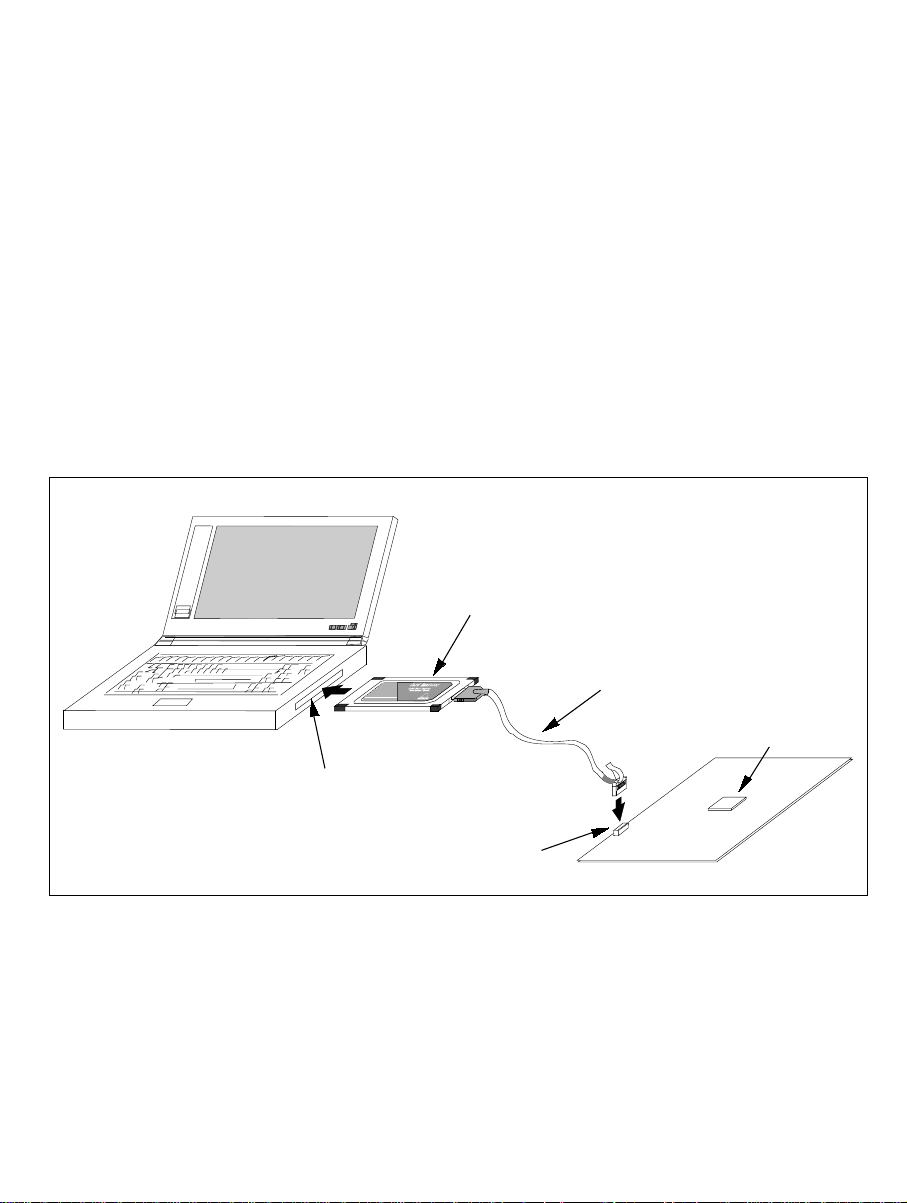
Host computer (PC with PCMCIA TYPE II slot)
PCMCIA card emulator
PC
PC
Card
Insert into the PCMCIA TYPE II slot
Connect to the Hitachi-UDI port connector
User system interface cable
H8S/xxxx
User system
Figure 1.1 System Configuration with the Emulator (PCMCIA Card Emulator Used)
1
Page 26
User system interface cable
PCI card emulator
H8S/xxxx
Insert into
the PCI slot
User system
Host computer
(PC with PCI slot)
Figure 1.2 System Configuration with the Emulator (PCI Card Emulator Used)
The emulator provides the following features:
• Excellent cost-performance card emulator
Compactness and low price are implemented using the PCMCIA interface or the PCI interface.
• Realtime emulation
Realtime emulation of the user system is enabled at the m aximum operating frequency of th e
CPU.
• Excellent operability
Using the Hitachi Debugging Interface (HDI) on the Microsoft
®
Windows® 98, Microsoft
Windows® Me, Microsoft® Windows NT®, and Microsoft® Windows® 2000 operating systems
enable user program debugging using a pointing device such as a mouse. The HDI enables
high-speed downloading of load module files.
• Various debugging functions
Various break and trace functions enable efficient debugging. Breakpoints and break
conditions can be set by the specific window, trace information can be displayed on a window,
and command-line functions can be used.
• Memory access during emulation
During emulation, the memory contents can be read and modified.
• Debugging of the user system in the final development stage
The user system can be debugged under conditions similar to the actual application conditions.
• Compact debugging environment
When the card emulator specific to the PCMCIA interface is used, a laptop computer can be
used as a host computer, creating a debugging environment in any place.
®
2
Page 27

1.1 Warnings
CAUTION
READ the following warnings before using the emulator
product. Incorrect operation will damage the user system and
the emulator product. The USER PROGRAM will be LOST.
1. Check all components against the component list after unpacking the emulator.
2. Never place heavy objects on the casing.
3. Protect the emulator from excessive impacts and stresses. For details, refer to section 1.2,
Environmental Conditions.
4. Do not insert the emulator into any slot (PCMCIA TYPE II slot or PCI slot) other than the
specified one.
5. When moving the host computer or user system, take care not to vibrate or damage it.
6. After connecting the cable, check that it is connected correctly. For details, refer to section 2,
Preparation before Use.
7. Supply power to the connected equipment after connecting all cables. Cables must not be
connected or removed while the power is on.
3
Page 28

1.2 Environmental Conditions
CAUTION
Observe the conditions listed in tables 1.1 and 1.2 when
using the emulator. Failure to do so will damage the user
system and the emulator product. The USER PROGRAM will
be LOST.
Table 1.1 Environmental Conditions
Item Specifications
Temperature Operating: +10°C to +35°C
Storage: –10°C to +50°C
Humidity Operating: 35% RH to 80% RH, no condensation
Storage: 35% RH to 80% RH, no condensation
Vibration Operating: 2.45 m/s2 max.
Storage: 4.9 m/s
Transportation: 14.7 m/s
Ambient gases There must be no corrosive gases present
Table 1.2 lists the acceptable operating environments.
2
max.
2
max.
4
Page 29

Table 1.2 Operating Environments
Item Description
Host computer Built-in Pentium or higher-performance CPU (200 MHz or higher
recommended); IBM PC or compatible machine with the PCMCIA
TYPE II slot or the PCI slot.
OS Windows® 98, Windows® Me, Windows NT®, or Windows® 2000
Minimum memory
capacity
Hard-disk capacity Installation disk capacity: 10 Mbytes or more. (Prepare an area at
Pointing device such as
mouse
Power voltage 5.0 ± 0.25 V
Current consumption HS0005KCM05H: 60 mA (max)
CD-ROM drive Required to install the emulator or refer to the emulator user’s manual.
32 Mbytes or more (double of the load module size recommended)
least double the memory capacity (four-times or more recommended)
as the swap area.)
Connectable to the host computer; compatible with Windows® 98,
Windows
®
Me, Windows NT®, and Windows® 2000.
HS0005KCI05H: 55 mA (max)
5
Page 30

1.3 Components
Check all the components unpacking. For details on the E10A emulator components, refer to
section 6.1, Components of the Emulator. If the components are not complete, contact a Hitachi
sales agency.
6
Page 31

Section 2 Preparation before Use
2.1 Emulator Preparation
WARNING
READ the reference sections shaded in figure 2.1 before
using the emulator product. Incorrect operation will damage
the user system and the emulator product. The USER
PROGRAM will be LOST.
Unpack the emulator and prepare it for use as follows:
Reference
Unpack the emulator
Check the components against the component list
Turn on the host computer
Install the HDI
Turn off the host computer
Insert the card emulator into the host computer
and connect the emulator to the user system
Turn on the host computer
Start the HDI
Turn on the user system
Figure 2.1 Emulator Preparation Flow Chart
Component list
Section 2.2
Section 2.3
Section 3
When the emulator
is used first.
When the emulator
is used for second
time or later.
7
Page 32

2.2 HDI Installation
When the CD-R is inserted in the host computer’s CD-ROM d r ive, the HDI installation wizard is
automatically activated (holding the Shift key down while the CD-R is inserted cancels this
automatic activation). To run the installation wizard when it has not been automatically activated,
execute Setup.exe from the root directory of the CD-R.
Follow the cues given by the in stallation wizard to install the HDI.
Since hardware settings are also made during installation, the installation procedure differs
according to the operating system or interface (PCI or PCMCIA) being used. Follow the
installation steps carefully according to the environment you are using.
2.2.1 Installing under Windows
98 and Windows
Me Operating Systems
(1) When the emulator is a PCI card:
1. Install the HDI (when the component type has to be selected during installation, be sure to
select [PCI Card Driver]).
2. Shut the operating system down and turn off the power to the host computer.
3. Insert the PCI-card emulator in a slot on the host computer. Refer to section 2.3,
Connecting the Host Computer with the Card Emulator.
4. Restart the host computer. The hardware is now recognized and the driver is automatically
installed.*
(2) When the emulator is a PCMCIA card:
1. Install the HDI (when the component type has to be selected during installation, be sure to
select [PC Card Driver (PCMCIA)]).
2. Insert the PCMCIA-card emulator in the host computer’s slot. Refer to section 2.3,
Connecting the Host Computer with the Card Emulator.
3. The hardware is now recognized and the driver is automatically installed.*
Note: When [Add New Hardware Wizard] is displayed, select the [Search for the best driver for
your device. (Recommended)] radio button and then the [Specify a location] check box to
select the path to be searched for drivers. The location must be specified according to the
emulator type, as indicated below:
When using the PCI-card emulator: <Drive>:\DRIVERS\PCI\95
When using the PCMCIA-card emulator: <Drive>:\DRIVERS\PCMCIA\95
(<Drive> is the CD-ROM drive name.)
8
Page 33

2.2.2 Installing under Windows NT
4.0 Operating System
(1) When the emulator is a PCI card:
1. Shut the operating system down and turn off the power to the host computer.
2. Insert the PCI-card emulator in a slot on the host computer. Refer to section 2.3,
Connecting the Host Computer with the Card Emulator.
3. Start the host computer and log-on with an administrator-level user name.
4. Install the HDI. (For a component, be sure to select [PCI Card Driver]. There is a check
box for selecting the type name of the product under the [PCI Card Driver] component.
Select the appropriate type name. If the correct name is not selected, the correct driver will
not be installed, and the emulator will not o perate.)
5. Restart the host computer.
(2) When the emulator is a PCMCIA card:
1. Shut the operating system down and turn off the power to the host computer.
2. Insert the PCMCIA-card emulator in the host computer’s slot. Refer to section 2.3,
Connecting the Host Computer with the Card Emulator.
3. Start the host computer and log-on with an administrator-level user name.
4. During HDI installation, the setting value should be checked beforehand because inquiries
are made about the resource used by the PCMCIA-card emulator.
Start the [Start] menu -> [Programs] -> [Administrative Tools (Common)] -> [Windows
NT Diagnostics], check the status of the IRQ, I/O port, and memory from the resource
panel, and determine the setting values that do not conflict with other devices. (The
following resources are used: IRQ: one channel, I/O port: H’F byte, and memory: H’4000
byte.)
5. Install the HDI. (For a component, be sure to select [PC Card Driver (PCMCIA)]. There is
a check box for selecting the type name of each product under the [PC Card Driver
(PCMCIA)] component. Select the appropriate type name. If the correct name is not
selected, the correct driver will not be installed and th e em ulator will not operate.)
6. Restart the host computer.
Note: The driver that has been selected in the [Drivers] component starts after the host computer
is initiated. If the host computer is initiated with the card disconnected or with the
incorrect driver installed, the driver cannot initiate and the service control manager
informs the system of an error. This, however, is not a problem.
9
Page 34

2.2.3 Installing under Windows2000 Operating System
(1) When the emulator is a PCI card:
1. Log-on with an administrator-level user name.
2. Install the HDI. (When a component is selected, be sure to select [PCI Card Driver].)
3. Shut the operating system down and turn off the power to the host computer.
4. Insert the PCI-card emulator in a slot on the host computer. Refer to section 2.3,
Connecting the Host Computer with the Card Emulator.
5. Restart the host computer and log-on with an administrator-level user name. The hardware
is now recognized and the driver is automatically installed.*
(2) When the emulator is a PCMCIA card:
1. Log-on with an administrator-level user name.
2. Install the HDI. (When a component is selected, be sure to select [PC Card Driver
(PCMCIA)].)
3. Insert the PCMCIA-card emulator in the host computer’s slot. Refer to section 2.3,
Connecting the Host Computer with the Card Emulator.
4. The hardware is now recognized and the driver is automatically installed.*
Note: When [Found New Hardware Wizard] is displayed, select the [Search for a suitable driver
for my device (recommended).] radio button and then the [Specify a location] check box
to select the path to be searched for drivers. The location must be specified according to
the emulator type, as indicated below:
When using the PCI-card emulator: <Drive>:\DRIVERS\PCI\2000
When using the PCMCIA-card emulator: <Drive>:\DRIVERS\PCMCIA\2000
(<Drive> is the CD-ROM drive name.)
10
Page 35

2.3 Connecting the Host Computer with the Card Emulator
Insert the card emulator into the PCMCIA TYPE II slot or the PCI slot of the host computer
(figures 2.2 and 2.3).
Note: Be sure to install the HDI before the card emulator is inserted.
Figure 2.2 Inserting the PCMCIA Card Emulator into the Host Computer
Figure 2.3 Inserting the PCI Card Emulator into t he Host Computer
Use the procedure, described in section 2.4, to connect the emulator to the user system with the
user system interface cable, or to disconnect them when moving the emulator or the user system.
11
Page 36

Note: When installing the PCI card emulator, note the following:
1. Turn off the host computer.
2. Insert the emulator into the PCI slot in parallel.
3. Screw in the emulator after confirming the connector and cable positions.
2.4 Connecting the Card Emulator with the User System
(1) The connector must be installed to the user system. Table 2.1 shows the recommended
connector for the emulator.
Table 2.1 Recommended Connector
Type Number Manufacturer Specifications
2514-6002 3M Limited 14-pin straight type
Note: When the connector is used, do not install any components within 3 mm of the
connector.
(2) The pin arrangement of the connector is shown in section 6.2, Pin Arrangement of the Hitachi-
UDI Port Connector.
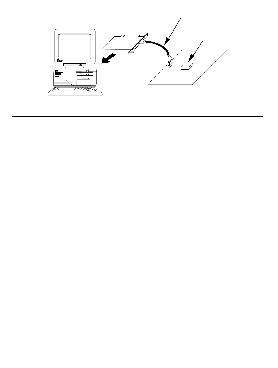
(3) Figure 2.4 shows how to connect the user system interface cable to the user system. Connect
the ground line of the cable to the user system ground. The end of the ground line has a hole
having a diameter of 3 mm, and therefore, when the ground line is screwed to the user sy stem,
the screw diameter must be 3 mm.
12
Figure 2.4 Connecting the User System Interface Cable to the User System
Page 37

Notes: 1. To connect the signals output from the connector, refer to the MCU pin
alignment.
2. To remove the user system interface cable from the user system, pull the tab
on the connector upward.
3. The range of communications that the emulator operates at is different
according to the MCUs used.
4. Connect the signals from the connector as shown in section 6.2, Pin
Arrangement of the Hitachi-UDI Port Connector.
13
Page 38

2.5 System Check
When the HDI program is executed, check that the emulator operates correctly according to the
following procedure:
1. Check that the card emulator is inserted into the host computer.
2. Connect the user system interface cable to the connector of the card emulator.
3. Connect the user system interface cable to the Hitachi-UDI port connector.
4. Power on the host computer and select [HDI for E10A H8Sxxxx] -> [Hitachi Debugging
Interface] from the [Start] menu.
14
Figure 2.5 [Start] Menu
Page 39

5. Power on the user system and select the setting to be used.
Figure 2.6 [Select Session] Dialog Box
15
Page 40

6. The [E10A Driver Details] dialog box is displayed. With the [Driver] combo box, select the
driver to connect the HDI with the emulator. [Interface] displays the interface name of the PC
interface board to be connected, and [Channel] displays the interface to which the board is
connected. Once the driver is selected in the [E10A Driver Details] dialog box, this dialog
box is not displayed when the HDI is run next time. (This procedure will not be executed by
target MCUs.)
Figure 2.7 [E10A Driver Details] Dialog Box
• With the [Driver] combo box, select the driver to connect the HDI with the emulator.
• [Interface] displays the interface name of the card emulator to be connected, and [Channel]
displays the interface to which the board is connected.
[Driver] combo box: Select [E10A PC Card Driver 5] to use th e PCMCIA card emulator.
Select [E10A PCI Card Driver 5] to use the PCI card emulator. For
details, refer to table 6.3 in section 6.4.1, Emulator Driver Selection.
[Interface] combo box: Select [PC Card] to use the PCMCIA card emulator.
Select [PCI] to use the PCI card emulator. (If the driver is not
installed, the [PC Card] or [PCI] is not displayed.)
• Click the [Close] button.
16
Page 41

7. Supply power to the user system.
The subsequent procedures depend on the activation mode that was selected in step 5.
2.5.1 H8S/xxxx E10A Emulator Mode
This mode is used for debugging in the emulator.
1. After the [System Clock] window appears, input the system clock frequency. This frequency
value is used when writing and erasing flash memory in the emulator.
Figure 2.8 [System Clock] Dialog Box
2. Set an eight-digit hexadecimal ID code as a security code for the flash memory. Input this ID
code when [H8S/xxxx E10A Emulator] is selected and the [New registration] check box is
unselected on activating the HDI. If the ID code is not matched, th e flash memory contents
are erased.
Figure 2.9 [ID Code] Dialog Box
3. When "Link up" appears on the status bar, the user and emulator programs have been
downloaded to the flash memory, an d the HDI initialization is complete.
Figure 2.10 [HDI] Status Bar
17
Page 42

Notes: 1. When the HDI is not linked up even if the above procedure has been executed, the
driver will not be set correctly. Install drivers provided with the \SETUP
directory in the CD-R according to the screen instructions.
2. If the user system interface cable is disconnected to the Hitachi-UDI port
connector on the user system during user program execution, the following dialog
box will be displayed.
Figure 2.11 [H-UDI Connector Disconnected] Dialog Box
3. If the emulator is not initiated, the following dialog boxes shown in figures 2.12
through 2.15 will be displayed.
(a) If the following dialog box is displayed, the user system may not be turned on or
the RESET signal may not have been correctly input to the MCU. Check the
power supply and input circuit for the reset pin on the user system.
18
Figure 2.12 [Can not find /RESET signal] Dialog Box
Page 43

(b) If the following dialog box is displayed, check that the Hitachi-UDI port
connector on the user system is correctly connected.
Figure 2.13 [Check the connection] Dialog Box
(c) If the following dialog box is displayed, the MCU may not correctly operate.
Check if there are reasons for illegal MCU operation.
Figure 2.14 [COMMUNICATION TIMEOUT ERROR] Dialog Box
Figure 2.15 [INVALID ASERAM FIRMWARE!] Dialog Box
19
Page 44
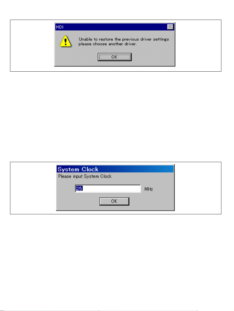
4. If the driver is not correctly connected, the following dialog box will be displayed.
Figure 2.16 [Unable to restore the previous driver settings] Dialog Box
The [E10A Driver Details] dialog box is displaye d when the [OK] button is clicked.
Select the correct driver. For details, refer to section 6.4.1, Emulator Driver
Selection.
2.5.2 Writing H8S/xxxx E10A Flash memory Mode
In this mode the emulator is used as a flash memory writer. The following procedures apply when
[Writing H8S/xxxx E10A Flash memory] is selected from the activation modes listed in the
[Select Session] dialog box.
1. After the [System Clock] window appears, input the system clock frequency.
20
Figure 2.17 [System Clock] Dialog Box
Page 45

2. When the [Load Program] window appears, specify a user program to be downloaded. Click
the [Open] button to start downloading.
Figure 2.18 [Load Program] Dialog Box
3. When the program has been downloaded, the memory area that the checksum value and the
program code have been written ap pears.
Figure 2.19 Checksum Value after Downloading the Program
Figure 2.20 [HDI] Dialog Box
21
Page 46

4. The [Continue] window appears. When the [OK] button is clicked, a message is disp layed to
request that power be supplied. Turn off the power, exchange the MCU, and supply power.
Repeat operations 1 to 3 until the [Exit] bu tto n is clicked. When the [Exit] button is clicked ,
the HDI is terminated.
Figure 2.21 [Continue?] Window
Notes: 1. When the HDI does not link up, and the above procedures have been executed, the
driver setting must be incorrect. Install a driver from the \SETUP directory of
the CD-R according to the screen instructions.
2. If the user system interface cable is disconnected from the connector on the user
system, the following dialog box will appear .
22
Figure 2.22 [Connector disconnected] Dialog Box
3. If the emulator is not properly initialized, the follo wing dialog box will appear.
If the following dialog box is display e d, t he f lash memory cannot be erased.
Exchange the MCU since the flash memory has been rewritten to more times than
the guaranteed value.
Figure 2.23 [Flash memory erase error!] Dialog Box
Page 47

2.6 Ending the HDI
Power off the emulator by using the following procedure:
1. Select [Exit] from the [File] menu to end the HDI. When the [Exit HDI] dialog box is
displayed, click the [Yes] button.
Figure 2.24 [Exit HDI] Dialog Box
2. Then, the [Save session] dialog box is displayed. If necessary, click the [Yes] button to save
session. After saving session, the HDI ends. If not necessary, click the [No] button to end the
HDI.
3. Turn the user system off.
Figure 2.25 [Save session] Dialog Box
23
Page 48

2.7 Uninstalling the HDI
Follow this procedure to remove the installed HDI from the user’s host computer.
1. Open [Add/Remove Programs Properties] from the control panel. Select the HDI program
from the list and click the [Add/Remove…] button.
2. The setup program is executed again and the installed application can be changed, modified,
or removed. When the application is to be uninstalled, select removal.
CAUTION
A shared file may be detected while the program is being
removed. If another HDI may be using the shared file, do not
remove the file. When Microsoft Windows NT4.0 operating
system is used, the removal of the registry information on the
driver may be asked. If other HDI may use the target driver,
do not remove the registry information. If another HDI does
not start up after the removal process, re-install that HDI.
24
Page 49

Section 3 Tutorial
3.1 Introduction
The following describes the main functions of the emulator by using a tutorial program.
The tutorial program is based on the C program that sorts ten random data items in ascending or
descending order. The tutorial program performs the following actions:
The
•
The
•
The
•
The tutorial program is included in the
the Sysrof format and is included in the
Table 3.1 lists the tutorial program configuration.
Table 3.1 Tutorial Program: Configuration and Parts
Item Contents
Workspace for HEW V1.2 [Installation directory]\tutorial\tutorial.hws
Load module [Installation directory]\tutorial\tutorial\Debug\tutorial.abs
Main program (source file) [Installation directory]\tutorial\tutorial\tutorial.c
Stack information file [Installation directory]\tutorial\tutorial\Debug\tutorial.sni
Notes: 1. This section describes general usage examples of the emulator. For each product
function generates random data to be sorted.
main
function sorts the generated random data in ascending order.
sort
change
2. This program was created by using Hitachi Embedded Workshop (hereafter
3. This program was compiled without optimization. If recompiled with different
4. tutorial.abs is a load module in the Dwarf2 format. If a load module is
5. This section describes general usage examples for the emulator. For the
function then sorts the data in descending order.
sort.c
tutorial.abs
specifications, refer to section 6 or on-line help.
referred to as HEW) V1.2. Older versions of HEW will not open the workspace
included with the package, so create a new workspace in such situations.
settings, the addresses may differ from those given in this section.
recreated in the Sysrof format, the amount of information displayed on the HDI
screen during the program’s execution will be reduced.
specifications of particular products, refer to section 6 or the online help file.
file. The compiled load module is provided in
file.
25
Page 50

3.2 Running the HDI
To run the HDI, select [HDI for E10A H8Sxxxx] -> [Hitachi Debugging Interface] from the
[Start] menu.
Figure 3.1 [Start] Menu
For the procedure of running the HDI, refer to section 2.5, System Check.
26
Page 51

3.3 [HDI] Window
Figure 3.2 [HDI] Window
The key functions of the HDI are described in section 4, Descriptions of Windows. Numbers in
figure 3.2 indicate the following:
1. Menu bar: Gives the user access to the HDI commands for using the HDI debugger.
2. Toolbar: Provides convenient buttons as shortcuts for the most frequently used menu
commands.
3. Program window: Displays the source program being debugged.
4. Status bar: Displays the status of the emulator, and progress information about
downloading.
5. [Help] button: Activates on-line help about any features of the HDI user interface.
27
Page 52

3.4 Setting up the Emulator
The following MCU conditions must be set up on the emulator before downloading the program:
• Device type
• Execution mode
The following describes how to set up the emulator for the tutorial programs.
3.5 Setting the [Configuration] Dialog Box
• Select [Configure Platform...] from the [Setup] menu to set configuration. The
[Configuration] dialog box is displayed.
Figure 3.3 [Configuration] Dialog Box
Note: The items that can be set in this window differ according to the product. For the
settings for each product, refer to the on-line help.
28
Page 53

Set options as follows:
Table 3.2 Setting the [Configuration] Dialog Box
Option Value
Mode H8S/xxxx (default)
Emulation mode Normal (normal execution, default)
Step option (Disables interrupt during single step
execution)
JTAG clock 4.125 MHz (default)
Operating Mode Operating mode determined by setting the
Flash memory synchronization Disable (default)
Disables interrupts during single step
execution (default)
mode pin (default)
• Click the [OK] button to set any changes in the configuration.
29
Page 54
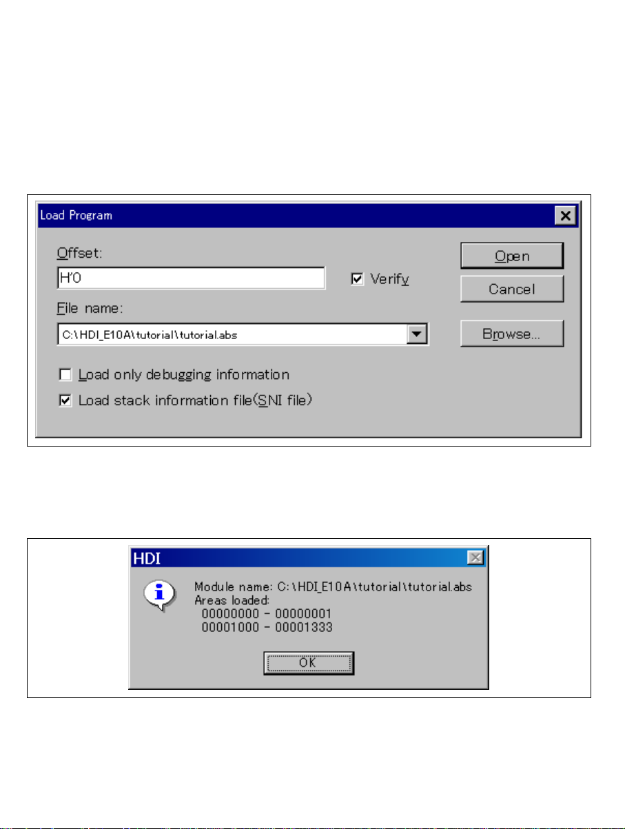
3.6 Downloading the Tutorial Program
3.6.1 Downloading the Tutorial Program
Download the object program to be debugged.
• Select [Load Program...] from the [File] menu. The [Load Program] dialog box is displayed.
Enter the [Offset] edit box and [File name] list box as shown in figure 3.4 and click the [Open]
button.
Figure 3.4 [Load Program] Dialog Box
When the file has been loaded, the following dialog box displays information about the
memory areas that have been filled with the pr ogram code.
Figure 3.5 [HDI] Dialog Box
• Click the [OK] button to continue.
30
Page 55

3.6.2 Displaying the Source Program
The HDI allows the user to debug a program at the source level.
• Select [Source...] from the [View] menu. The [Open] dialog box is displayed.
• Select the C source file that corresponds to the object file the user has loaded.
Figure 3.6 [Open] Dialog Box
31
Page 56

• Select [Sort.c] and click the [Open] button. The [Program] window is displayed.
Figure 3.7 [Program] Window (Displaying the Source Program)
• If necessary, select the [Font...] option from the [Customize] submenu on the [Setup] menu to
select a clear font and size.
Initially the [Program] window shows the start of the main program, but the user can use the scroll
bar to scroll through the program to see the other statements.
32
Page 57

3.7 Setting the Software Breakpoint
A breakpoint is one of the easy debugging functions.
The [Program] window provides a very simple way of setting a software breakpoint at any point
in a program. For example, to set a breakpoint at the sort function call:
• Select by double-clicking the [BP] column on the line containing the sort function call.
Figure 3.8 [Program] Window (Setting a Software Breakpoint)
The word [
a software breakpoint is set.
•
Break] will be displayed on the line containing the sort function to show that
33
Page 58

3.8 Setting Registers
Set values of the program counter and the stack pointer before executing th e program.
• Select [Registers] from the [View] menu. The [Registers] window is displayed.
Figure 3.9 [Registers] Window
• To change the value of the program counter (PC), double-click the value area in the
[Registers] window with the mouse. The following dialog box is then displayed, and the value
can be changed.
Figure 3.10 [Register] Dialog Box (PC)
• Set the program counter to H’1000 in this tutorial program, and click the [OK] button.
• To change the value of the stack pointer (SP), move the mouse pointer on the value to be
changed in the [ER7] value area in the [Registers] window and enter the new value by the
34
Page 59

keyboard, or double-click the value area with the mouse. The following dialog box is then
displayed.
Figure 3.11 [Register] Dialog Box (ER7)
• Set the value of the stack pointer to H’FFFC00 in this tutorial progr am , and click the [OK]
button.
35
Page 60

3.9 Executing the Program
Execute the program as described in the following:
• To execute the program, select [Go] from the [Run] menu, or click the [Go] button on the
toolbar.
Figure 3.12 [Go] Button
• Or, select [Reset Go] from the [Run] menu or click the [Reset Go] button on the toolbar.
Figure 3.13 [Reset Go] Button
The program will be executed up to the breakpoint that has been inserted, and a statement will
be highlighted in the [Program] window to show the position that the program has halted, with
the message [Break=BREAKPOINT] in the status bar.
36
Figure 3.14 [Program] Window (Break Status)
Page 61

The user can see the cause of the break that occurred last time in the [System Status] window.
• Select [Status] from the [View] menu. After the [System Status] window is displayed, open
the [Platform] page, and check the status of Cause of last break.
Figure 3.15 [System Status] Windo w
Note: The items that can be displayed in this window differ a ccording to the product. For
the items that can be displayed, refer to the on-line help.
37
Page 62

The [System Status] window displays the following items in each page.
Table 3.3 Contents of the [System Stat us] Window
Page Item Description
[Session] Target System Always displays Connected.
Session Name Displays the session file name.
Program Name Displays the load module file name.
[Platform] Connected To: Displays the name of the connected emulator and the
selected driver name.
CPU Displays the target MCU name.
Run status Displays the execution status:
RUNNING: Being executed
Break: Stopped
Cause of last break Displays the cause of the emulator stopping at break. In
this example, the cause of the stop is BREAK POINT.
Run time count Displays the program execution time. The display format
is h: hours, min: minutes, s: seconds, and ms:
milliseconds. In this example, 0h0min3s110ms is
displayed.
Emulator mode Displays the emulator operating mode (setting
information for [Emulation Mode] of the [Configuration]
dialog box).
[Memory] Loaded Memory
Areas
[Events] Resources Displays the usage states of BREAKPOINT and Break
Displays the loaded area of the load module.
Condition.
38
Page 63

3.10 Reviewing Breakpoints
The user can see all the breakpoints set in the program in the [Breakpoints] window.
• Select [Breakpoints] from the [View] menu.
Figure 3.16 [Breakpoints] Window
The pop-up menu, opened by clicking the [Breakpoints] window with the right mouse button,
also allows the user to set or change breakpoints, define new breakpoints, and delete, enable,
or disable breakpoints.
39
Page 64

3.11 Viewing Memory
The user can view the contents of a memory block in the [Memory] window. For example, to
view the memory contents corresponding to the main in word size:
• Select [Memory …] from the [View] menu, enter
Word in the [Format] combo box.
Figure 3.17 [Open Memory Window] Dialog Box
• Click the [OK] button. The [Memory] window showing the specified area of memory is
displayed.
main
in the [Address] edit box, and set
40
Figure 3.18 [Memory] Window
Page 65

3.12 Watching Variables
As the user steps through a program, it is possible to watch that the values of variables used in the
user program are changed. For example, set a watch on the long-type array a declared at the
beginning of the program, by using the following procedure:
• Click the left of displayed array a in the [Program] window to position the cursor.
• Click the [Program] window with the right mouse button and select [Instant Watch...] from a
pop-up menu.
The following dialog box will be displayed.
Figure 3.19 [Instant Watch] Dialog Box
41
Page 66

• Click [Add Watch] button to add a variable to the [Watch] window.
Figure 3.20 [Watch] Window (Displaying the Array)
The user can also add a variable to the [Watch] window by specifying its name.
• Click the [Watch] window with the right mouse button and select [Add Watch] from the pop-
up menu.
The following dialog box will be displayed.
Figure 3.21 [Add Watch] Dialog Box
• Input variable
42
max
and click the [OK] button.
Page 67

The [Watch] window will now also show the long-type variable max.
Figure 3.22 [Watch] Window (Displaying the Variable)
The user can double-click the + symbol to the left of any variable in the [Watch] window to
watch the all elements in array a.
Figure 3.23 [Watch] Window (Displaying Array Elements)
43
Page 68

3.13 Stepping Through a Program
The HDI provides a range of step menu commands that allow efficient program debugging.
Table 3.4 Step Option
Menu
Command Description
Step In Executes each statement, including statements within functions.
Step Over Executes a function call in a single step.
Step Out Steps out of a function, and stops at the statement following the statement in the
program that called the function.
Step… Steps the specified times repeatedly at a specified rate.
44
Page 69

3.13.1 Executing [Step In] Command
The [Step In] steps into the called function and stops at the first statement of the called function.
• To step through the sort function, select [Step In] from the [Run] menu, or click the [Step
In] button in the toolbar.
Figure 3.24 [Step In] Button
Figure 3.25 [Program] Window (Step In)
• The highlighted line moves to the first statement of the sort function in the [Program]
window.
45
Page 70

3.13.2 Executing [Step Out] Command
The [Step Out] steps out of the called function an d stops at the next statement of the calling
statement in the main function.
• To step out of the sort function, select [Step Out] from the [Run] menu, or click the [Step
Out] button in the toolbar.
Figure 3.26 [Step Out] Button
Figure 3.27 [Program] Window (Step Out)
• The data of variable a displayed in the [Watch] window is sorted in ascending order.
46
Page 71

• To execute two steps, use [Step In] twice.
Figure 3.28 [Program] Window (Step In −> Step In)
• The value of max displayed in the [Watch] window is changed to the maximum data value.
47
Page 72

3.13.3 Execut ing [Step Over] Command
The [Step Over] executes a function call as a single step and stops at the next statement of the
main program.
• Using [Step Over], execute two steps to reach the change function statement.
Figure 3.29 [Program] Window (Before Step Over Execution)
• To step through all statements in the change function at a single step, select [Step Over] from
the [Run] menu, or click the [Step Over] button in the toolbar.
Figure 3.30 [Step Over] Button
48
Page 73

Figure 3.31 [Program] Window (Step Over)
When the last statement of the change function is executed, the data of variable a, which is
displayed in the [Watch] window, is sorted in descending order.
49
Page 74

3.14 Displaying Local Variables
The user can display local variables in a function using the [Locals] window. For example, we
will examine the local variables in the main function, which declares five local variables: a, j, i,
min, and max.
• Select [Locals] from the [View] menu. The [Locals] window is displayed.
Initially, the [Locals] window is empty because local variables have not yet been declared.
• Select [Step In] from the [Run] menu to execute a single step.
The [Locals] window will now show the local variables and their values.
Figure 3.32 [Locals] Window
• Double-click the + symbol in front of array a in the [Locals] window to display the elements
of array a.
• Refer to the elements of array a before and after the execution of the sort function, and
confirm that random data is sorted in descending order.
50
Page 75

3.15 Break Function
The emulator has software and hardware break functions. With the HDI, a so ftware breakpoint
can be set using the [Breakpoints] window, and a hardware break condition can be set using the
[Break condition 1] dialog box.
An overview and setting of the break function are described below.
3.15.1 Software Break Function
The emulator can set up to 255 software breakpoints. Setting a software breakpoint is described
below.
• Select [Breakpoints] from the [View] menu. The [Breakpoints] window is displayed.
• Click the [Breakpoints] window with the right mouse button and select [Delete All] from the
pop-up menu to cancel all the breakpoints that have been set.
Figure 3.33 [Breakpoints] Window (Before Software Breakpoint Setting)
• Click the [Breakpoints] window with the right mouse button and select [Add] from the pop-up
menu.
51
Page 76

The [Break] dialog box is displayed. The [Point] page is displayed as a default.
Figure 3.34 [Point] Page ([Break] Dialog Box)
• Click the [Add...] button to display the [Breakpoint] dialog box.
52
Page 77

• Enter
H'10a4
to the [Value] edit box.
• Click the [OK] button.
Figure 3.35 [Breakpoint] Dialog Box
53
Page 78

The [Break] dialog box is displayed. The address set in the value field of [Breakpoint] is
displayed.
Figure 3.36 [Point] Page ([Break] Dialog Box) (After Software Breakpoint Setting)
• Click the [Close] button.
54
Page 79

The software breakpoint that has been set is displayed in the [Breakpoints] window.
Figure 3.37 [Breakpoints] Window (Software Breakpoint Setting)
To stop the tutorial program at the breakpoint, the following procedure must be executed:
• Close the [Breakpoints] window.
• Click the [Reset Go] button.
The program runs, and stops at the set breakpoint.
Figure 3.38 [Program] Window at Execution Stop (Software Break)
55
Page 80

The [System Status] window displays the following contents.
Figure 3.39 Displayed Contents of the [System Status] Window (Software Break)
Note: The items that can be displayed in this window differ a ccording to the product. For
the items that can be displayed, refer to the on-line help.
56
Page 81

3.16 Hardware Break Function
A method is given below in which the address bus condition and the read cycles for the state
condition are set under Break condition 1 as hardware break conditions.
• Select [Breakpoint Window] from the [View] menu. The [Breakpoints] window is displayed.
• Click the [Breakpoints] window with the right mouse button and select [Delete All] from the
pop-up menu to cancel all breakpoints that have been set.
• Click the [Breakpoints] window with the right mouse button and select [Add] from the pop-up
menu.
Figure 3.40 [Breakpoints] Window (Before Hardware Break Condition Setting)
57
Page 82

The [Break] dialog box is displayed. To set hardware break conditions, select [Condition] in the
[Break] dialog box to display the [Condition] page.
Figure 3.41 [Condition] Page ([Break] Dialog Box)
Up to two breakpoints can be set independently for the hardware break condition. In this example,
set the hardware break condition for Break condition 1.
Note: Note that the number of hardware brea k conditions differs according to the product.
For the number that can be specified for each product, refer to the on-line help.
58
Page 83

• Highlight the first point in the [Break condition] list box.
• Click the [Edit...] button. The [Break condition 1] dialog box is displayed.
• Clear the [Don't care] check box in the [Address] page.
• Select the [Only program fetched address after] radio button and enter
H'108C
the [Address] edit box.
as the value in
Figure 3.42 [condition] Page ([Break condition 1] Dialog Box)
Note: The items that can be set in this window differ according to the product. For the
settings for each product, refer to the on-line help.
• Click the [OK] button.
• The [Break] dialog box is displayed. Check the first point display in the [Break condition] list
box is changed from Empty to Enable.
59
Page 84

Figure 3.43 [Break] Dialog Box (After Hardware Break Condition Setting)
Note: Note that the number of hardware brea k conditions differs according to the product.
For the number that can be specified for each product, refer to the on-line help.
• Click the [Close] button.
60
Page 85

The newly set hardware breakpoint is displayed in the [Breakpoints] window. With this setting,
Break condition 1 is displayed in [Type] in the [Breakpoints] window.
This completes the setting of the Break condition 1 hardware break condition. When the program
is executed, a break will occur when address H'108C is accessed in a read cycle.
Figure 3.44 [Breakpoints] Window ([Break condit ion 1] Setting)
• Close the [Breakpoints] window.
• Click the [Reset Go] button.
61
Page 86

The program runs then stops at the condition specified under Break condition 1.
62
Figure 3.45 [Program] Window at Execution Stop (Break condition 1)
Page 87

The [System Status] window displays the following contents.
Figure 3.46 Displayed Contents of the [System Status] Window (Break condition 1)
Note: The items that can be displayed in this window differ a ccording to the product. For
the items that can be displayed, refer to the on-line help.
63
Page 88

3.17 Trace Function
The trace function of the E10A emulator is described.
The branch source addresses, mnemonics, operands, and source lines are displayed. Since this
function uses the trace buffer built into the MCU, a realtime trace can b e acq uired.
Run the program as shown in the example of section 3.15.1, Software Break Function. The trace
results are displayed in the [Trace] window after the program execution is completed.
Figure 3.47 [Trace] Window
• If necessary, adjust the column width by d r ag ging the header bar immediately below the title
bar.
Note: The number of branch instructions that can be acquired by a trace differs according
to the product. For the number that can be specified for each product, refer to the
on-line help.
64
Page 89

3.18 What Next?
This tutorial has described the major features of the emulator and the use of the HDI.
Sophisticated debugging can be carried out by using the emulation functions that the emulator
offers. This provides for effective investigation of hardware and software problems by accurately
isolating and identifying the conditions under which such problems arise.
Further details on the use of the HDI can be found in the separately issued Hitachi Debugging
Interface User's Manual.
65
Page 90

66
Page 91

Section 4 Descriptions of Windows
4.1 HDI Windows
HDI window menu bars and the corresponding pull-down menus are listed in table 4.1. Where a
description of a menu is included in the Hitachi Debugging Interface User's Manual or in this
manual, an O mark or the relevant section number is shown. Related commands in the E10A
Emulator User's Manual are also shown.
Table 4.1 HDI Window Menus and Related Ma nual Entries
Hitachi
Debugging
Menu Bar Pull-Down Menu
File menu New Session…
Load Session…
Save Session
Save Session As…
Load Program…
Initialize
Exit
Edit Menu Cut
Copy
Paste
Find…
Evaluate…
Interface
User's Manual
O
O
O
O
O
O
O
O
O
O
O
O
This
Manual
—
—
2.6
—
3.6.1
—
—
—
—
—
—
—
67
Page 92

Table 4.1 HDI Window Menus and Related Ma nual Entries (cont)
Hitachi
Debugging
Menu Bar Pull-Down Menu
View Menu Breakpoints
Command Line
Disassembly...
I/O Registers
Labels
Locals
Memory...
Performance Analysis
Profile-List
Profile-Tree
Registers
Source…
Status
Trace
Watch
Localized Dump Window
Run Menu Reset CPU
Go
Reset Go
Go to Cursor
Set PC To Cursor
Run…
Step In
Step Over
Step Out
Step…
Halt
Interface
User's Manual
O
O
O
O
O
O
O
O
O
O
O
O
O
O
O
O
O
O
O
O
O
O
O
O
O
O
O
This
Manual
3.10, 3.15.1, 4.2.3, 6.4.3
—
—
—
—
3.14
3.11
—
—
—
3.8
3.6.2
3.9, 3.15.1, 4.2.9
4.2.8, 6.4.4
3.12
—
—
3.9
—
—
—
—
3.13.1
3.13.3
3.13.2
—
—
68
Page 93

Table 4.1 HDI Window Menus and Related Ma nual Entries (cont)
Hitachi
Debugging
Interface
Menu Bar Pull-Down Menu
Memory Menu Refresh
Load
Save
Verify
Test
Fill
Copy
Compare
Setup Menu Status bar
Options
Radix
Customise
Configure Platform…
Window Menu Cascade
Tile
Arrange Icons
Close All
Help Menu Index
Using Help
Search for Help on
About HDI
User's Manual This Manual
O
O
O
O
O
O
O
O
O
O
O
O
O
O
O
O
O
O
O
O
O
—
—
—
—
—
—
—
—
—
—
—
—
3.5, 4.2
—
—
—
—
—
—
—
—
69
Page 94

4.2 Descriptions of Each Window
This section describes each window. Figures in this section are used as examples. Each E10A
emulator type has explanatory notes. Read section 6, H8S/xxxx E10A Emulator Specifications.
4.2.1 [Configuration] Dialog Box
Function:
This dialog box sets the emulation conditions of the emulator.
Window:
Figure 4.1 [Configuration] Dialog Box
Note: The items that can be set in this window differ according to the product. For the
settings for each product, refer to the on-line help.
70
Page 95

Description:
The [Configuration] dialog box consists of the [General] page listed in table 4.2.
Table 4.2 [Configuration] Dialog Box Page
Page Name Description
[General] Sets the emulator operation conditions.
Clicking the [OK] button sets the emulation conditions. If the [Cancel] button is clicked, this
dialog box is closed without setting the emulation conditions.
71
Page 96

(1) [General] Page ([Configuration] Dialog Box)
Function:
This page sets the operational conditions for the emulator. The MCU name is displayed, the
emulation mode and interrupts during step execution are set, the JTAG clock (TCK) is displayed
and set, and the driver is selected.
Window:
Figure 4.2 [General] Page ([Configuration] Dialog Box)
Note: The items that can be set in this window differ according to the product. For the
settings for each product, refer to the on-line help.
72
Page 97

Description:
Table 4.3 [General] Page Options
Option Description
[Mode] combo box Displays the MCU name.
[Emulation mode] combo box Selects the emulation mode at user program execution. Select
Normal to perform normal emulation. Select No Break to disable
breakpoint settings.
[Step option] combo box Enables or disables interrupts during step execution.
Disables interrupts during single step execution: Interrupts during
step execution are masked.
Enables interrupts during single step execution: Interrupts during
step execution are released.
[JTAG clock] combo box Sets the JTAG frequency*.
[Operating mode] combo box Displays the operating mode determined by the MD pin.
[Flash memory synchronization]
combo box
[Driver] group box The [E10A Driver Details] dialog box is displayed. Changes the
Note: The range of frequencies that the JTAG operates at is different according to the devices
used. For details, refer to section 6.5.4, Notes on Using the JTAG Clock (TCK).
Synchronization method is set between the host computer and
the flash memory.
When synchronization is performed from the host computer to
the flash memory, a waiting time will be generated to write the
flash memory during user program halting, but the displayed
contents and the flash memory are always matched.
When synchronization is performed from the flash memory to the
host computer, the rewritten contents in the user program mode
will be reflected since the flash memory is read during user
program halting.
Disable: Synchronization is not performed except when the
E10A emulator is activated and the flash memory area is
modified.
PC to Flash memory: Synchronization is performed from the
host computer t the flash memory.
Flash memory to PC: Synchronization is performed from the
flash memory to the host computer.
PC to Flash memory, Flash memory to PC: Synchronization is
performed between the host computer and the flash memory.
driver currently connected.
73
Page 98

When a driver is to be changed with the [Change…] button, the follo wing message is displayed.
Figure 4.3 Warning Message Box
When the [Yes] button is clicked, the [E10A Driver Details] dialog box is displayed. When the
[No] button is clicked, the display returns to the [Configuration] dialog box.
Related Items:
[Configuration] dialog box
GO_OPTION command
STEP_INTERRUPT command
74
Page 99

4.2.2 [E10A Driver Details] Dialog Box
When the [OK] button is clicked, the [E10A Driver Details] dialog box will appear to select the
driver software used by the interface to the emulator . Since the emulator is reinitialized after this
dialog box is closed, it cannot be cancelled.
Figure 4.4 [E10A Driver Details] Dialog Box
Table 4.4 shows each option.
Table 4.4 [E10A Driver Details] Dialog Box Option
Option Description
[Driver] combo box Selects the driver to connect the HDI with the emulator.
[Interface] combo box Selects the interface name of the card emulator to be connected.
[Channel] combo box Selects the interface that the PC interface board has been connected.
[Configure...] button Clicked to display that the driver supports the configuration dialog box.
75
Page 100

When the PCMCIA card emulator is used, [E10A PC Card Driver 5] is selected. When the PCI
card emulator is used, [E10A PCI Card Driver 5] is selected.
Note: When the HDI is not linked up even if the above procedure has been executed, the driver
may not be set correctly. Install drivers provided with the \SETUP directory in the CD-R
according to the screen instructions.
Related Items:
[Configuration] dialog box
[General] page
4.2.3 [Breakpoints] Window
Function:
This window lists all break conditions that have been set.
Window:
76
Figure 4.5 [Breakpoints] Window
 Loading...