

Page 1

To all our customers
Regarding the change of names mentioned in the document, such as Hitachi
Electric and Hitachi XX, to Renesas Technology Corp.
The semiconductor operations of Mitsubishi Electric and Hitachi were transferred to Renesas
Technology Corporation on April 1st 2003. These operations include microcomputer, logic, analog
and discrete devices, and memory chips other than DRAMs (flash memory, SRAMs etc.)
Accordingly, although Hitachi, Hitachi, Ltd., Hitachi Semiconductors, and other Hitachi brand
names are mentioned in the document, these names have in fact all been changed to Renesas
Technology Corp. Thank you for your understanding. Except for our corporate trademark, logo and
corporate statement, no changes whatsoever have been made to the contents of the document, and
these changes do not constitute any alteration to the contents of the document itself.
Renesas Technology Home Page: http://www.renesas.com
Renesas Technology Corp.
Customer Support Dept.
April 1, 2003
Page 2

Cautions
Keep safety first in your circuit designs!
1. Renesas Technology Corporation puts the maximum effort into making semiconductor products better
and more reliable, but there is al ways the possibility that t rouble may occur with them. Trouble with
semiconductors may lead to personal injury, fire or property damage.
Remember to give due consideration to safety when making your circuit designs, with appropriate
measures such as (i) placement of substitutive, auxiliary circuits, (ii) use of nonflammable material or
(iii) prevention against any malfunction or mishap.
Notes regarding these materials
1. These materials are intended as a reference to assist our customers in th e sel ection of the Renesas
Technology Corporation product best suited to the customer's application; they do not convey any
license under any intellectual property rights, or any other rights, belonging to Renesas Technology
Corporation or a third party.
2. Renesas Technology Corporation assumes no responsibility for any damage, or infringement of any
third-party's rights, originating in the use of any product data, diagrams, charts, programs, algorithms, or
circuit application examples contained in these materi als.
3. All information contained in these materials, including product data, diagrams, charts, programs and
algorithms represents information on products at the time of publication of these materials, and are
subject to change by Renesas Technology Corporation without notice due to product improvements or
other reasons. It is therefore recommended that customers contact Renesas Technology Corporation
or an authorized Renesas Technology Corporation product distributor for the latest product information
before purchasing a product listed herein.
The information described here may contain technical i naccuracies or typographical errors.
Renesas Technology Corporation assumes no responsibility for any damage, liability, or other loss
rising from these inaccuracies or errors.
Please also pay attention to information published by Renesas Technology Corporation by various
means, including the Renesas Technology Corporation Semiconductor home page
(http://www.renesas.com).
4. When using any or all of the information contained in these materials, including product data, diagrams,
charts, programs, and algorithms, please be sure to evaluat e al l information as a total system before
making a final decision on the applicability of the information and products. Renesas Technology
Corporation assumes no responsibility for any damage, liability or other loss resulting from the
information contained herein.
5. Renesas Technology Corporation semiconductors are not designed or manufactured for use in a device
or system that is used under circumstances in which human life is po t entially at stake. P l ease contact
Renesas Technology Corporation or an authorized Renesas Technology Corporation product distributor
when considering the use of a product contained herein for any specific purposes, such as apparatus or
systems for transportation, vehicular, medical, aerospace, n uclear, or undersea repeater use.
6. The prior written approval of Renesas Technology Corporation is necessary to reprint or reproduce in
whole or in part these materials.
7. If these products or technologies are subject to the Japanese export control restrictions, they must be
exported under a license from the Japanese government and cannot be imported into a country other
than the approved destination.
Any diversion or reexport contrary to the export control laws and regulations of Japan and/or the
country of destination is prohibited.
8. Please contact Renesas Technology Corporation for further details on these materials or the products
contained therein.
Page 3

H8/3834 Series
H8/3837
HD6433837, HD6433837S, HD64473837
H8/3836
HD6433836, HD6433836S
H8/3835
HD6433835, HD6433835S
H8/3834
HD6433834, HD6433834S, HD6473834
H8/3833
HD6433833, HD6433833S
H8/3832
HD6433832S
ADE-602-054D
Rev. 5.0
3/5/03
Hitachi, Ltd.
MC-Setsu
Hardware Manual
Page 4

Notice
When using this document, keep the following in mind:
1. This document may, wholly or partially, be subject to change without notice.
2. All rights are reserved: No one is permitted to reproduce or duplicate, in any form, the whole
or part of this document without Hitachi’s permission.
3. Hitachi will not be held responsible for any damage to the user that may result from accidents
or any other reasons during operation of the user’s unit according to this document.
4. Circuitry and other examples described herein are meant merely to indicate the characteristics
and performance of Hitachi’s semiconductor products. Hitachi assumes no responsibility for
any intellectual property claims or other problems that may result from applications based on
the examples described herein.
5. No license is granted by implication or otherwise under any patents or other rights of any third
party or Hitachi, Ltd.
6. MEDICAL APPLICATIONS: Hitachi’s products are not authorized for use in MEDICAL
APPLICATIONS without the written consent of the appropriate officer of Hitachi’s sales
company. Such use includes, but is not limited to, use in life support systems. Buyers of
Hitachi’s products are requested to notify the relevant Hitachi sales offices when planning to
use the products in MEDICAL APPLICATIONS.
Page 5

Preface
The H8/300L Series of single-chip microcomputers has the high-speed H8/300L CPU at its core,
with many necessary peripheral functions on-chip. The H8/300L CPU instruction set is compatible
with the H8/300 CPU.
The H8/3834 Series has a system-on-a-chip architecture that includes such peripheral functions as
an LCD controller/driver, five types of timers, a 14-bit PWM, a three-channel serial
communication interface, and an A/D converter. This makes it ideal for use in systems requiring
an LCD display.
This manual describes the hardware of the H8/3834 Series. For details on the H8/3834 Series
instruction set, refer to the H8/300L Series Programming Manual.
Note: The terms H8/3834, H8/3834S, and H8/3834 Series used in the text refer to the products
shown below.
1. H8/3834: HD6433837, HD6433836, HD6433835, HD6433834, HD6433833,
HD6473837, HD6473834
2. H8/3834S: HD6433837S, HD6433836S, HD6433835S, HD6433834S, HD6433833S,
HD6433832S
3. H8/3834 Series: All products, including the H8/3834 and H8/3834S
Page 6

Page 7

Contents
Section 1 Overview............................................................................................................ 1
1.1 Overview............................................................................................................................ 1
1.2 Internal Block Diagram...................................................................................................... 5
1.3 Pin Arrangement and Functions......................................................................................... 6
1.3.1 Pin Arrangement ................................................................................................... 6
1.3.2 Pin Functions......................................................................................................... 8
Section 2 CPU...................................................................................................................... 13
2.1 Overview............................................................................................................................ 13
2.1.1 Features ................................................................................................................. 13
2.1.2 Address Space ....................................................................................................... 14
2.1.3 Register Configuration.......................................................................................... 14
2.2 Register Descriptions.......................................................................................................... 15
2.2.1 General Registers.................................................................................................. 15
2.2.2 Control Registers................................................................................................... 15
2.2.3 Initial Register Values........................................................................................... 17
2.3 Data Formats...................................................................................................................... 17
2.3.1 Data Formats in General Registers........................................................................ 18
2.3.2 Memory Data Formats .......................................................................................... 19
2.4 Addressing Modes.............................................................................................................. 20
2.4.1 Addressing Modes................................................................................................. 20
2.4.2 Effective Address Calculation............................................................................... 22
2.5 Instruction Set .................................................................................................................... 26
2.5.1 Data Transfer Instructions..................................................................................... 28
2.5.2 Arithmetic Operations........................................................................................... 30
2.5.3 Logic Operations................................................................................................... 31
2.5.4 Shift Operations .................................................................................................... 31
2.5.5 Bit Manipulations.................................................................................................. 33
2.5.6 Branching Instructions.......................................................................................... 37
2.5.7 System Control Instructions.................................................................................. 39
2.5.8 Block Data Transfer Instruction............................................................................ 40
2.6 Basic Operational Timing.................................................................................................. 41
2.6.1 Access to On-Chip Memory (RAM, ROM).......................................................... 41
2.6.2 Access to On-Chip Peripheral Modules................................................................ 42
2.7 CPU States.......................................................................................................................... 43
2.7.1 Overview............................................................................................................... 43
2.7.2 Program Execution State....................................................................................... 45
2.7.3 Program Halt State................................................................................................ 45
2.7.4 Exception-Handling State ..................................................................................... 45
i
Page 8

2.8 Memory Map...................................................................................................................... 46
2.8.1 Memory Map......................................................................................................... 46
2.8.2 LCD RAM Address Relocation............................................................................ 52
2.9 Application Notes............................................................................................................... 53
2.9.1 Notes on Data Access............................................................................................ 53
2.9.2 Notes on Bit Manipulation.................................................................................... 55
2.9.3 Notes on Use of the EEPMOV Instruction ........................................................... 61
Section 3 Exception Handling........................................................................................ 63
3.1 Overview............................................................................................................................ 63
3.2 Reset................................................................................................................................... 63
3.2.1 Overview............................................................................................................... 63
3.2.2 Reset Sequence...................................................................................................... 63
3.2.3 Interrupt Immediately after Reset ......................................................................... 65
3.3 Interrupts............................................................................................................................ 66
3.3.1 Overview............................................................................................................... 66
3.3.2 Interrupt Control Registers.................................................................................... 67
3.3.3 External Interrupts................................................................................................. 75
3.3.4 Internal Interrupts.................................................................................................. 76
3.3.5 Interrupt Operations.............................................................................................. 76
3.3.6 Interrupt Response Time....................................................................................... 81
3.4 Application Notes............................................................................................................... 81
3.4.1 Notes on Stack Area Use ...................................................................................... 81
3.4.2 Notes on Rewriting Port Mode Registers.............................................................. 82
Section 4 Clock Pulse Generators.................................................................................. 85
4.1 Overview............................................................................................................................ 85
4.1.1 Block Diagram...................................................................................................... 85
4.1.2 System Clock and Subclock.................................................................................. 85
4.2 System Clock Generator..................................................................................................... 86
4.3 Subclock Generator............................................................................................................ 88
4.4 Prescalers............................................................................................................................ 91
4.5 Note on Oscillators............................................................................................................. 92
Section 5 Power-Down Modes....................................................................................... 93
5.1 Overview............................................................................................................................ 93
5.1.1 System Control Registers...................................................................................... 96
5.2 Sleep Mode......................................................................................................................... 99
5.2.1 Transition to Sleep Mode...................................................................................... 99
5.2.2 Clearing Sleep Mode............................................................................................. 99
5.3 Standby Mode .................................................................................................................... 99
5.3.1 Transition to Standby Mode.................................................................................. 99
5.3.2 Clearing Standby Mode ........................................................................................ 100
ii
Page 9

5.3.3 Oscillator Settling Time after Standby Mode is Cleared...................................... 100
5.3.4 Transition to Standby Mode and Port Pin States .................................................. 101
5.4 Watch Mode....................................................................................................................... 101
5.4.1 Transition to Watch Mode .................................................................................... 101
5.4.2 Clearing Watch Mode ........................................................................................... 102
5.4.3 Oscillator Settling Time after Watch Mode is Cleared......................................... 102
5.5 Subsleep Mode................................................................................................................... 102
5.5.1 Transition to Subsleep Mode ................................................................................ 102
5.5.2 Clearing Subsleep Mode ....................................................................................... 103
5.6 Subactive Mode.................................................................................................................. 103
5.6.1 Transition to Subactive Mode ............................................................................... 103
5.6.2 Clearing Subactive Mode...................................................................................... 103
5.6.3 Operating Frequency in Subactive Mode.............................................................. 103
5.7 Active (medium-speed) Mode............................................................................................ 104
5.7.1 Transition to Active (medium-speed) Mode......................................................... 104
5.7.2 Clearing Active (medium-speed) Mode................................................................ 104
5.7.3 Operating Frequency in Active (medium-speed) Mode........................................ 104
5.8 Direct Transfer.................................................................................................................... 104
5.8.1 Direct Transfer Overview...................................................................................... 104
5.8.2 Calculation of Direct Transfer Time before Transition ........................................ 106
Section 6 ROM.................................................................................................................... 109
6.1 Overview............................................................................................................................ 109
6.1.1 Block Diagram...................................................................................................... 109
6.2 H8/3834 PROM Mode ....................................................................................................... 110
6.2.1 Setting to PROM Mode......................................................................................... 110
6.2.2 Socket Adapter Pin Arrangement and Memory Map............................................ 110
6.3 H8/3834 Programming....................................................................................................... 113
6.3.1 Writing and Verifying........................................................................................... 113
6.3.2 Programming Precautions ..................................................................................... 117
6.4 H8/3837 PROM Mode ....................................................................................................... 118
6.4.1 Setting to PROM Mode......................................................................................... 118
6.4.2 Socket Adapter Pin Arrangement and Memory Map............................................ 118
6.5 H8/3837 Programming....................................................................................................... 121
6.5.1 Writing and Verifying........................................................................................... 121
6.5.2 Programming Precautions ..................................................................................... 126
6.6 Reliability of Programmed Data ........................................................................................ 127
Section 7 RAM.................................................................................................................... 129
7.1 Overview............................................................................................................................ 129
7.1.1 Block Diagram...................................................................................................... 129
Section 8 I/O Ports ............................................................................................................. 131
iii
Page 10

8.1 Overview............................................................................................................................ 131
8.2 Port 1.................................................................................................................................. 133
8.2.1 Overview............................................................................................................... 133
8.2.2 Register Configuration and Description................................................................ 133
8.2.3 Pin Functions......................................................................................................... 137
8.2.4 Pin States............................................................................................................... 139
8.3 Port 2.................................................................................................................................. 140
8.3.1 Overview............................................................................................................... 140
8.3.2 Register Configuration and Description................................................................ 140
8.3.3 Pin Functions......................................................................................................... 144
8.3.4 Pin States............................................................................................................... 144
8.4 Port 3.................................................................................................................................. 145
8.4.1 Overview............................................................................................................... 145
8.4.2 Register Configuration and Description................................................................ 145
8.4.3 Pin Functions......................................................................................................... 149
8.4.4 Pin States............................................................................................................... 151
8.4.5 MOS Input Pull-Up............................................................................................... 151
8.5 Port 4.................................................................................................................................. 152
8.5.1 Overview............................................................................................................... 152
8.5.2 Register Configuration and Description................................................................ 152
8.5.3 Pin Functions......................................................................................................... 154
8.5.4 Pin States............................................................................................................... 155
8.6 Port 5.................................................................................................................................. 155
8.6.1 Overview............................................................................................................... 155
8.6.2 Register Configuration and Description................................................................ 156
8.6.3 Pin Functions......................................................................................................... 158
8.6.4 Pin States............................................................................................................... 158
8.6.5 MOS Input Pull-Up............................................................................................... 159
8.7 Port 6.................................................................................................................................. 159
8.7.1 Overview............................................................................................................... 159
8.7.2 Register Configuration and Description................................................................ 160
8.7.3 Pin Functions......................................................................................................... 161
8.7.4 Pin States............................................................................................................... 162
8.7.5 MOS Input Pull-Up............................................................................................... 162
8.8 Port 7.................................................................................................................................. 163
8.8.1 Overview............................................................................................................... 163
8.8.2 Register Configuration and Description................................................................ 163
8.8.3 Pin Functions......................................................................................................... 164
8.8.4 Pin States............................................................................................................... 165
8.9 Port 8.................................................................................................................................. 165
8.9.1 Overview............................................................................................................... 165
8.9.2 Register Configuration and Description................................................................ 165
8.9.3 Pin Functions......................................................................................................... 167
iv
Page 11

8.9.4 Pin States............................................................................................................... 167
8.10 Port 9.................................................................................................................................. 168
8.10.1 Overview ............................................................................................................... 168
8.10.2 Register Configuration and Description................................................................ 168
8.10.3 Pin Functions......................................................................................................... 169
8.10.4 Pin States............................................................................................................... 171
8.11 Port A.................................................................................................................................. 171
8.11.1 Overview ............................................................................................................... 171
8.11.2 Register Configuration and Description................................................................ 172
8.11.3 Pin Functions......................................................................................................... 173
8.11.4 Pin States............................................................................................................... 174
8.12 Port B.................................................................................................................................. 175
8.12.1 Overview ............................................................................................................... 175
8.12.2 Register Configuration and Description................................................................ 175
8.13 Port C.................................................................................................................................. 176
8.13.1 Overview ............................................................................................................... 176
8.13.2 Register Configuration and Description................................................................ 176
Section 9 Timers................................................................................................................. 177
9.1 Overview............................................................................................................................ 177
9.2 Timer A.............................................................................................................................. 178
9.2.1 Overview............................................................................................................... 178
9.2.2 Register Descriptions............................................................................................ 180
9.2.3 Timer Operation.................................................................................................... 182
9.2.4 Timer A Operation States...................................................................................... 183
9.3 Timer B .............................................................................................................................. 183
9.3.1 Overview............................................................................................................... 183
9.3.2 Register Descriptions............................................................................................ 185
9.3.3 Timer Operation.................................................................................................... 187
9.3.4 Timer B Operation States...................................................................................... 188
9.4 Timer C .............................................................................................................................. 188
9.4.1 Overview............................................................................................................... 188
9.4.2 Register Descriptions............................................................................................ 190
9.4.3 Timer Operation.................................................................................................... 192
9.4.4 Timer C Operation States...................................................................................... 194
9.5 Timer F............................................................................................................................... 194
9.5.1 Overview............................................................................................................... 194
9.5.2 Register Descriptions............................................................................................ 197
9.5.3 Interface with the CPU.......................................................................................... 203
9.5.4 Timer Operation.................................................................................................... 206
9.5.5 Application Notes.................................................................................................. 208
9.6 Timer G.............................................................................................................................. 210
9.6.1 Overview............................................................................................................... 210
v
Page 12

9.6.2 Register Descriptions............................................................................................ 212
9.6.3 Noise Canceller Circuit......................................................................................... 215
9.6.4 Timer Operation.................................................................................................... 217
9.6.5 Application Notes.................................................................................................. 221
9.6.6 Sample Timer G Application................................................................................ 224
Section 10 Serial Communication Interface ................................................................. 225
10.1 Overview........................................................................................................................... 225
10.2 SCI1.................................................................................................................................... 225
10.2.1 Overview............................................................................................................... 225
10.2.2 Register Descriptions............................................................................................ 227
10.2.3 Operation............................................................................................................... 231
10.2.4 Interrupts ............................................................................................................... 234
10.2.5 Application Notes.................................................................................................. 234
10.3 SCI2.................................................................................................................................... 234
10.3.1 Overview............................................................................................................... 234
10.3.2 Register Descriptions ............................................................................................ 236
10.3.3 Operation............................................................................................................... 240
10.3.4 Interrupts ............................................................................................................... 247
10.3.5 Application Notes.................................................................................................. 247
10.4 SCI3.................................................................................................................................... 248
10.4.1 Overview............................................................................................................... 248
10.4.2 Register Descriptions............................................................................................ 250
10.4.3 Operation............................................................................................................... 266
10.4.4 Operation in Asynchronous Mode ........................................................................ 270
10.4.5 Operation in Synchronous Mode .......................................................................... 278
10.4.6 Multiprocessor Communication Function ............................................................ 285
10.4.7 Interrupts ............................................................................................................... 291
10.4.8 Application Notes.................................................................................................. 292
Section 11 14-Bit PWM...................................................................................................... 297
11.1 Overview............................................................................................................................ 297
11.1.1 Features ................................................................................................................. 297
11.1.2 Block Diagram...................................................................................................... 297
11.1.3 Pin Configuration.................................................................................................. 298
11.1.4 Register Configuration.......................................................................................... 298
11.2 Register Descriptions.......................................................................................................... 298
11.2.1 PWM Control Register (PWCR)........................................................................... 298
11.2.2 PWM Data Registers U and L (PWDRU, PWDRL)............................................. 299
11.3 Operation............................................................................................................................ 299
Section 12 A/D Converter.................................................................................................. 301
12.1 Overview............................................................................................................................ 301
vi
Page 13

12.1.1 Features ................................................................................................................. 301
12.1.2 Block Diagram...................................................................................................... 301
12.1.3 Pin Configuration.................................................................................................. 302
12.1.4 Register Configuration.......................................................................................... 302
12.2 Register Descriptions.......................................................................................................... 303
12.2.1 A/D Result Register (ADRR)................................................................................ 303
12.2.2 A/D Mode Register (AMR) .................................................................................. 303
12.2.3 A/D Start Register (ADSR)................................................................................... 305
12.3 Operation............................................................................................................................ 306
12.3.1 A/D Conversion Operation.................................................................................... 306
12.3.2 Start of A/D Conversion by External Trigger Input.............................................. 306
12.4 Interrupts ............................................................................................................................ 307
12.5 Typical Use ........................................................................................................................ 307
12.6 Application Notes............................................................................................................... 310
Section 13 LCD Controller/Driver .................................................................................. 311
13.1 Overview............................................................................................................................ 311
13.1.1 Features ................................................................................................................. 311
13.1.2 Block Diagram...................................................................................................... 312
13.1.3 Pin Configuration.................................................................................................. 313
13.1.4 Register Configuration.......................................................................................... 313
13.2 Register Descriptions.......................................................................................................... 314
13.2.1 LCD Port Control Register (LPCR)...................................................................... 314
13.2.2 LCD Control Register (LCR)................................................................................ 316
13.3 Operation............................................................................................................................ 318
13.3.1 Settings Prior to LCD Display .............................................................................. 318
13.3.2 Relation of LCD RAM to Display ........................................................................ 320
13.3.3 Connection to HD66100........................................................................................ 320
13.3.4 Operation in Power-Down Modes ........................................................................ 329
13.3.5 Boosting the LCD Driver Power Supply .............................................................. 330
Section 14 Electrical Characteristics............................................................................... 331
14.1 H8/3832S, H8/3833S, H8/3834S, H8/3835S, H8/3836S and H8/3837S
Absolute Maximum Ratings (Standard Specifications)..................................................... 331
14.2 H8/3832S, H8/3833S and H8/3834S Electrical Characteristics
(Standard Specifications).................................................................................................... 332
14.2.1 Power Supply Voltage and Operating Range........................................................ 332
14.2.2 DC Characteristics ................................................................................................ 334
14.2.3 AC Characteristics ................................................................................................ 339
14.2.4 A/D Converter Characteristics.............................................................................. 343
14.2.5 LCD Characteristics.............................................................................................. 344
14.3 H8/3835S, H8/3836S and H8/3837S Electrical Characteristics
(Standard Specifications).................................................................................................... 345
vii
Page 14

14.3.1 Power Supply Voltage and Operating Range........................................................ 345
14.3.2 DC Characteristics ................................................................................................ 347
14.3.3 AC Characteristics ................................................................................................ 352
14.3.4 A/D Converter Characteristics.............................................................................. 356
14.3.5 LCD Characteristics.............................................................................................. 357
14.4 H8/3832S, H8/3833S, H8/3834S, H8/3835S, H8/3836S and H8/3837S
Absolute Maximum Ratings (Wide Temperature Range (I-Spec) Version)...................... 358
14.5 H8/3832S, H8/3833S and H8/3834S Electrical Characteristics
(Wide Temperature Range (I-Spec) Version).................................................................... 359
14.5.1 Power Supply Voltage and Operating Range........................................................ 359
14.5.2 DC Characteristics ................................................................................................ 361
14.5.3 AC Characteristics ................................................................................................ 366
14.5.4 A/D Converter Characteristics.............................................................................. 370
14.5.5 LCD Characteristics.............................................................................................. 371
14.6 H8/3835S, H8/3836S and H8/3837S Electrical Characteristics
(Wide Temperature Range (I-Spec) Version).................................................................... 373
14.6.1 Power Supply Voltage and Operating Range........................................................ 373
14.6.2 DC Characteristics ................................................................................................ 375
14.6.3 AC Characteristics ................................................................................................ 380
14.6.4 A/D Converter Characteristics.............................................................................. 384
14.6.5 LCD Characteristics.............................................................................................. 385
14.7 H8/3833, H8/3834, H8/3835, H8/3836, and H8/3837 (Standard Specification)
Absolute Maximum Ratings............................................................................................... 387
14.8 H8/3833 and H8/3834 Electrical Characteristics (Standard Specifications)...................... 388
14.8.1 Power Supply Voltage and Operating Range........................................................388
14.8.2 DC Characteristics ................................................................................................ 390
14.8.3 AC Characteristics ................................................................................................ 395
14.8.4 A/D Converter Characteristics.............................................................................. 399
14.8.5 LCD Characteristics.............................................................................................. 400
14.9 H8/3835 and H8/3836 and H8/3837 (Standard Specifications)
Electrical Characteristics.................................................................................................... 401
14.9.1 Power Supply Voltage and Operating Range........................................................ 401
14.9.2 DC Characteristics ................................................................................................ 403
14.9.3 AC Characteristics ................................................................................................ 408
14.9.4 A/D Converter Characteristics.............................................................................. 412
14.9.5 LCD Characteristics.............................................................................................. 413
14.10 H8/3833, H8/3834, H8/3835, H8/3836, and H8/3837 Absolute Maximum Ratings
(Wide Temperature Range (I-Spec) Version).................................................................... 414
14.11 H8/3833 and H8/3834 Electrical Characteristics (Wide Temperature Range
(I-Spec) Version)................................................................................................................ 415
14.11.1 Power Supply Voltage and Operating Range........................................................ 415
14.11.2 DC Characteristics ................................................................................................ 417
14.11.3 AC Characteristics ................................................................................................ 422
viii
Page 15

14.11.4 A/D Converter Characteristics.............................................................................. 426
14.11.5 LCD Characteristics.............................................................................................. 427
14.12 H8/3835, H8/3836, and H8/3837 Electrical Characteristics
(Wide Temperature Range (I-Spec) Version).................................................................... 429
14.12.1 Power Supply Voltage and Operating Range........................................................ 429
14.12.2 DC Characteristics ................................................................................................ 431
14.12.3 AC Characteristics ................................................................................................ 436
14.12.4 A/D Converter Characteristics.............................................................................. 440
14.12.5 LCD Characteristics.............................................................................................. 441
14.13 Operation Timing ............................................................................................................... 443
14.14 Output Load Circuit............................................................................................................ 448
Appendix A CPU Instruction Set..................................................................................... 449
A.1 Instructions......................................................................................................................... 449
A.2 Operation Code Map.......................................................................................................... 457
A.3 Number of Execution States............................................................................................... 459
Appendix B On-Chip Registers........................................................................................ 466
B.1 I/O Registers (1) ................................................................................................................. 466
B.2 I/O Registers (2) ................................................................................................................. 470
Appendix C I/O Port Block Diagrams............................................................................ 513
C.1 Block Diagram of Port 1 .................................................................................................... 513
C.2 Block Diagram of Port 2 .................................................................................................... 518
C.3 Block Diagram of Port 3 .................................................................................................... 521
C.4 Block Diagram of Port 4 .................................................................................................... 527
C.5 Block Diagram of Port 5 .................................................................................................... 530
C.6 Block Diagram of Port 6 .................................................................................................... 531
C.7 Block Diagram of Port 7 .................................................................................................... 532
C.8 Block Diagram of Port 8 .................................................................................................... 533
C.9 Block Diagram of Port 9 .................................................................................................... 534
C.10 Block Diagram of Port A.................................................................................................... 535
C.11 Block Diagram of Port B.................................................................................................... 536
C.12 Block Diagram of Port C.................................................................................................... 536
Appendix D Port States in the Different Processing States....................................... 537
Appendix E List of Products Codes................................................................................. 538
Appendix F Package Dimensions..................................................................................... 542
ix
Page 16

Section 1 Overview
1.1 Overview
The H8/300L Series is a series of single-chip microcomputers (MCU: microcomputer unit), built
around the high-speed H8/300L CPU and equipped with peripheral system functions on-chip.
Within the H8/300L Series, the H8/3834 Series features an on-chip liquid crystal display (LCD)
controller/driver. Other on-chip peripheral functions include five timers, a 14-bit pulse width
modulator (PWM), three serial communication interface channels, and an analog-to-digital (A/D)
converter. Together these functions make the H8/3834 Series ideally suited for embedded control
of systems requiring an LCD display. On-chip memory is 16 kbytes of ROM and 1 kbyte of RAM
in the H8/3832S, 24 kbytes of ROM and 1 kbyte of RAM in the H8/3833(S), 32 kbytes of ROM
and 1 kbyte of RAM in the H8/3834(S), 40 kbytes of ROM and 2 kbytes of RAM in the
H8/3835(S), 48 kbytes of ROM and 2 kbytes of RAM in the H8/3836(S), and 60 kbytes of ROM
and 2 kbytes of RAM in the H8/3837(S).
The H8/3834 and H8/3837 both include a ZTAT™ version*, featuring a user-programmable onchip PROM.
Table 1.1 summarizes the features of the H8/3834 Series.
Note: * ZTAT is a trademark of Hitachi, Ltd.
Table 1.1 Features
Item Description
CPU High-speed H8/300L CPU
• General-register architecture
General registers: Sixteen 8-bit registers (can be used as eight 16-bit
registers)
• Operating speed
Max. operating speed: 5 MHz
Add/subtract: 0.4 µs (operating at 5 MHz)
Multiply/divide: 2.8 µs (operating at 5 MHz)
Can run on 32.768 kHz subclock
• Instruction set compatible with H8/300 CPU
Instruction length of 2 bytes or 4 bytes
Basic arithmetic operations between registers
MOV instruction for data transfer between memory and registers
1
Page 17

Table 1.1 Features (cont)
Item Description
CPU Typical instructions
• Multiply (8 bits × 8 bits)
• Divide (16 bits ÷ 8 bits)
• Bit accumulator
• Register-indirect designation of bit position
Interrupts 33 interrupt sources
• 13 external interrupt pins: IRQ
• 20 internal interrupt sources
Clock pulse generators Two on-chip clock pulse generators
• System clock pulse generator: 1 to 10 MHz
• Subclock pulse generator: 32.768 kHz
Power-down modes Six power-down modes
• Sleep mode
• Standby mode
• Watch mode
• Subsleep mode
• Subactive mode
• Active (medium-speed) mode
Memory Large on-chip memory
• H8/3832S: 16-kbyte ROM, 1-kbyte RAM
• H8/3833(S): 24-kbyte ROM, 1-kbyte RAM
• H8/3834(S): 32-kbyte ROM, 1-kbyte RAM
• H8/3835(S): 40-kbyte ROM, 2-kbyte RAM
• H8/3836(S): 48-kbyte ROM, 2-kbyte RAM
• H8/3837(S): 60-kbyte ROM, 2-kbyte RAM
I/O ports 84 I/O port pins
• I/O pins: 71
• Input pins: 13
Timers Five on-chip timers
• Timer A: 8-bit timer
Count-up timer with selection of eight internal clock signals divided
Note: *φ and
from the system clock (
watch clock (
φ
are defined in section 4, Clock Pulse Generators.
w
φ
)*
w
φ
)* and four clock signals divided from the
to IRQ0, WKP7 to WKP
4
0
2
Page 18

Table 1.1 Features (cont)
Item Description
Timers
Serial communication
interface
14-bit PWM Pulse-division PWM output for reduced ripple
A/D converter
LCD controller/driver Up to 40 segment pins and 4 common pins
• Timer B: 8-bit timer
Count-up timer with selection of seven internal clock signals or
event input from external pin
Auto-reloading
• Timer C: 8-bit timer
Count-up/count-down timer with selection of seven internal clock
signals or event input from external pin
Auto-reloading
• Timer F: 16-bit timer
Can be used as two independent 8-bit timers.
Count-up timer with selection of four internal clock signals or
event input from external pin
Compare-match function with toggle output
• Timer G: 8-bit timer
Count-up timer with selection of four internal clock signals
Input capture function with built-in noise canceller circuit
Three channels on chip
• SCI1: synchronous serial interface
Choice of 8-bit or 16-bit data transfer
• SCI2: 8-bit synchronous serial interface
Automatic transfer of 32-byte data segments
• SCI3: 8-bit synchronous or asynchronous serial interface
Built-in function for multiprocessor communication
• Can be used as a 14-bit D/A converter by connecting to an external
low-pass filter.
• Successive approximations using a resistance ladder resolution:
8 bits
• 12-channel analog input port
• Conversion time: 31/
• Choice of four duty cycles (static, 1/2, 1/3, 1/4)
• Segments can be expanded externally
• Segment pins can be switched to general-purpose ports in groups of
four
φ
or 62/φ per channel
3
Page 19

Table 1.1 Features (cont)
Item Description
Product lineup
Mask ROM Version ZTAT™ Version Package ROM/RAM Size
HD6433832SH
HD6433832SF
HD6433832SX
HD6433833H
HD6433833SH
HD6433833F
HD6433833SF
HD6433833X
HD6433833SX
HD6433834H
HD6433834SH
HD6433834F
HD6433834SF
HD6433834X
HD6433834SX
HD6433835H
HD6433835SH
HD6433835F
HD6433835SF
HD6433835X
HD6433835SX
HD6433836H
HD6433836SH
HD6433836F
HD6433836SF
HD6433836X
HD6433836SX
HD6433837H
HD6433837SH
HD6433837F
HD6433837SF
HD6433837X
HD6433837SX
HD6433832SD
HD6433832SE
HD6433832SL
HD6433833D
HD6433833SD
HD6433833E
HD6433833SE
HD6433833L
HD6433833SL
HD6433834D
HD6433834SD
HD6433834E
HD6433834SE
HD6433834L
HD6433834SL
HD6433835D
HD6433835SD
HD6433835E
HD6433835SE
HD6433835L
HD6433835SL
HD6433836D
HD6433836SD
HD6433836E
HD6433836SE
HD6433836L
HD6433836SL
HD6433837D
HD6433837SD
HD6433837E
HD6433837SE
HD6433837L
HD6433837SL
Product Code
—
—
—
—
—
—
HD6473834H
HD6473834F
HD6473834X
—
—
—
—
—
—
HD6473837H
HD6473837F
HD6473837X
—
—
—
—
—
—
HD6473834D
HD6473834E
—
—
—
—
—
—
—
HD6473837D
HD6473837E
HD6473837L
100-pin QFP (FP-100B)
100-pin QFP (FP-100A)
100-pin TQFP (TFP-100B)
100-pin QFP (FP-100B)
100-pin QFP (FP-100A)
100-pin TQFP (TFP-100B)
100-pin QFP (FP-100B)
100-pin QFP (FP-100A)
100-pin TQFP (TFP-100B)
100-pin QFP (FP-100B)
100-pin QFP (FP-100A)
100-pin TQFP (TFP-100B)
100-pin QFP (FP-100B)
100-pin QFP (FP-100A)
100-pin TQFP (TFP-100B)
100-pin QFP (FP-100B)
100-pin QFP (FP-100A)
100-pin TQFP (TFP-100B)
100-pin QFP (FP-100B)
100-pin QFP (FP-100A)
100-pin TQFP (TFP-100B)
100-pin QFP (FP-100B)
100-pin QFP (FP-100A)
100-pin TQFP (TFP-100B)
100-pin QFP (FP-100B)
100-pin QFP (FP-100A)
100-pin TQFP (TFP-100B)
100-pin QFP (FP-100B)
100-pin QFP (FP-100A)
100-pin TQFP (TFP-100B)
100-pin QFP (FP-100B)
100-pin QFP (FP-100A)
100-pin TQFP (TFP-100B)
100-pin QFP (FP-100B)
100-pin QFP (FP-100A)
100-pin TQFP (TFP-100B)
ROM: 16 kbytes
RAM: 1 kbyte
ROM: 24 kbytes
RAM: 1 kbyte
ROM: 32 kbytes
RAM: 1 kbyte
ROM: 40 kbytes
RAM: 2 kbytes
ROM: 48 kbytes
RAM: 2 kbytes
ROM: 60 kbytes
RAM: 2 kbytes
ROM: 16 kbytes
RAM: 1 kbyte
WTR (I-spec)
ROM: 24 kbytes
RAM: 1 kbyte
WTR (I-spec)
ROM: 32 kbytes
RAM: 1 kbyte
WTR (I-spec)
ROM: 40 kbytes
RAM: 2 kbytes
WTR (I-spec)
ROM: 48 kbytes
RAM: 2 kbytes
WTR (I-spec)
ROM: 60 kbytes
RAM: 2 kbytes
WTR (I-spec)
4
Page 20

1.2 Internal Block Diagram
Figure 1.1 shows a block diagram of the H8/3834 Series.
P10/TMOW
/TMOFL
P1
1
/TMOFH
P1
2
/TMIG
P1
3
/PWM
P1
4
/IRQ1/TMIB
P1
5
/IRQ2/TMIC
P1
6
/IRQ3/TMIF
P1
7
/IRQ4/ADTRG
P2
0
P2
P30/SCK
P31/SI
P32/SO
P33/SCK
P34/SI
P35/SO
P36/STRB
P3
/SCK
P4
0
P41/RXD
P4
2
P4
3
P50/WKP0/SEG
P51/WKP1/SEG
P52/WKP2/SEG
P53/WKP3/SEG
P54/WKP4/SEG
P55/WKP5/SEG
P56/WKP6/SEG
P57/WKP7/SEG
/UD
1
P2
P2
P2
P2
P2
P2
/CS
7
/TXD
/IRQ
2
OSC1OSC2X1X
oscillator
oscillator
Subclock
System clock
Port 1Port 2Port 3Port 4Port 5
2
3
4
5
6
7
1
1
1
2
2
2
3
0
1
2
3
4
5
6
7
8
CC
VSSVSSVCCV
CPU
H8/300L
RES
Data bus (lower)
ROM RAM
Timer A
LCD
controller
Timer B SCI1
Timer C SCI2
Timer F SCI3
Timer G
14-bit
PWM
A/D
converter
TEST
MDO
Address bus
LCD driver
Data bus (upper)
V
1
V
2
V
3
power supply
PA3/COM
PA2/COM
PA1/COM
Port A
PA0/COM
P97/SEG40/CL
P96/SEG39/CL
P95/SEG38/DO
P9
P9
P92/SEG
P91/SEG
P90/SEG
P87/SEG
P86/SEG
P85/SEG
P84/SEG
P83/SEG
P82/SEG
P81/SEG
P80/SEG
P77/SEG
P76/SEG
P75/SEG
P74/SEG
P73/SEG
Port 7 Port 8 Port 9
P72/SEG
P71/SEG
P70/SEG
P67/SEG
P66/SEG
P65/SEG
P64/SEG
P63/SEG
Port 6
P62/SEG
P61/SEG
P60/SEG
/SEG37/M
4
/SEG
3
4
3
2
1
1
2
36
35
34
33
32
31
30
29
28
27
26
25
24
23
22
21
20
19
18
17
16
15
14
13
12
11
10
9
Port B Port C
8
AVCCAV
0
1
2
3
4
5
6
SS
/AN
/AN
/AN
0
1
2
PB
PB
PB
/AN
3
PB
/AN
4
PB
/AN
5
PB
/AN
6
PB
7
/AN
7
PB
/AN
0
PC
9
/AN
1
PC
10
/AN
2
PC
11
/AN
3
PC
Figure 1.1 Block Diagram
5
Page 21

1.3 Pin Arrangement and Functions
1.3.1 Pin Arrangement
The pin arrangement of the H8/3834 Series is shown in figures 1.2 and 1.3.
/TMIF
/TXD
2
P4
4
/SEG
3
/WKP
3
P5
/RXD
1
P4
5
/SEG
4
/WKP
4
P5
3
/SCK
0
P4
6
/SEG
5
/WKP
5
P5
3
/IRQ
7
P1
7
/SEG
6
/WKP
6
P5
/IRQ2/TMIC
6
P1
8
/SEG
7
/WKP
7
P5
/IRQ1/TMIB
5
P1
9
/SEG
0
P6
/PWM
4
P1
10
/SEG
1
P6
/TMIG
3
P1
11
/SEG
2
P6
P2
/IRQ4/ADTRG
0
PC3/AN
AV
TEST
V
OSC
OSC
RES
MDO
P2
/UD
1
P2
P2
P2
P2
P2
P2
P30/SCK
P31/SI
P32/SO
P33/SCK
P34/SI
P35/SO
P36/STRB
10
9
8
7
6
5
4
3
2
/AN
/AN
/AN
/AN
/AN
/AN
2
1
0
PC
PC
PC
PB
100 99 98 97 96 95 94 93 92 91 90 89 88 87 86 85 84 83 82 81 80 79 78 77 76
1
11
2
SS
/AN
7
6
5
4
PB
PB
PB
/AN
3
PB
/AN
2
PB
1
/AN
1
PB
0
/AN
0
PB
AVCCP4
0
/IRQ
3
3
4
X
2
5
X
1
6
SS
7
1
8
2
9
10
11
12
13
2
14
3
15
4
16
5
17
6
18
7
19
1
20
1
21
1
22
2
23
2
24
2
25
26 27 28 29 30 31 32 33 34 35 36 37 38 39 40 41 42 43 44 45 46 47 48 49 50
1
2
/CS
P3
4
3
2
/COM
2
PA
/COM
1
PA
1
/COM
0
PA
V3V2V
1
CC
V
/COM
3
SS
V
7
PA
/SEG
0
/WKP
0
P5
/SEG
1
/WKP
1
P5
3
/SEG
2
/WKP
2
P5
/TMOFH
/TMOFL
2
1
P1
P1
12
13
/SEG
/SEG
3
4
P6
P6
/TMOW
0
CC
P1
V
75
74
73
72
71
70
69
68
67
66
65
64
63
62
61
60
59
58
57
56
55
54
53
52
51
14
15
/SEG
/SEG
5
6
P6
P6
P97/SEG40/CL
P96/SEG39/CL
P95/SEG38/DO
P9
/SEG37/M
4
P9
/SEG
3
36
P92/SEG
35
P91/SEG
34
P90/SEG
33
P87/SEG
32
P86/SEG
31
P85/SEG
30
P84/SEG
29
P83/SEG
28
P82/SEG
27
P81/SEG
26
P80/SEG
25
P77/SEG
24
P76/SEG
23
P75/SEG
22
P74/SEG
21
P73/SEG
20
P72/SEG
19
P71/SEG
18
P70/SEG
17
P67/SEG
16
1
2
Figure 1.2 Pin Arrangement (FP-100B, TFP-100B: Top View)
6
Page 22

7
/AN
7
PB
6
/AN
6
PB
5
/AN
5
PB
4
/AN
4
PB
3
/AN
3
PB
2
/AN
2
PB
1
/AN
1
PB
0
/AN
0
PB
/IRQ
AVCCP4
/TMIF
/TMIC
3
/IRQ
7
P1
2
/IRQ
6
P1
/TMIB
1
/IRQ
5
P1
/PWM
4
P1
/TMIG
3
P1
/TMOFH
/TMOFL
2
1
P1
P1
/TXD
2
P4
/RXD
1
P4
3
/SCK
0
P4
0
3
/IRQ4/ADTRG
P2
0
P36/STRB
PC0/AN
PC1/AN
PC2/AN
PC3/AN
AV
TEST
V
OSC
OSC
RES
MDO
/UD
P2
1
P2
P2
P2
P2
P2
P2
P30/SCK
P31/SI
P32/SO
P33/SCK
P34/SI
P35/SO
/CS
P3
7
V
100 99 98 97 96 95 94 93 92 91 90 89 88 87 86 85 84 83 82 81
1
8
2
9
3
10
4
11
5
SS
6
X
7
2
X
8
1
9
SS
10
1
11
2
12
13
14
15
16
2
17
3
18
4
19
5
20
6
21
7
22
1
23
1
24
1
25
2
26
2
27
2
28
29
30
SS
31 32 33 34 35 36 37 38 39 40 41 42 43 44 45 46 47 48 49 50
80
79
78
77
76
75
74
73
72
71
70
69
68
67
66
65
64
63
62
61
60
58
58
57
56
55
54
53
52
51
/TMOW
P1
0
V
CC
P97/SEG40/CL
P96/SEG39/CL
P95/SEG38/DO
/SEG37/M
P9
4
/SEG
P9
3
36
P92/SEG
35
P91/SEG
34
P90/SEG
33
P87/SEG
32
P86/SEG
31
P85/SEG
30
P84/SEG
29
P83/SEG
28
P82/SEG
27
P81/SEG
26
P80/SEG
25
P77/SEG
24
P76/SEG
23
P75/SEG
22
P74/SEG
21
P73/SEG
20
P72/SEG
19
P71/SEG
18
P70/SEG
17
P67/SEG
16
P66/SEG
15
P65/SEG
14
P64/SEG
13
1
2
1
2
3
4
5
6
7
/SEG
5
/WKP
5
P5
/SEG
6
/WKP
6
P5
8
/SEG
7
/WKP
7
P5
9
/SEG
0
P6
10
/SEG
1
P6
3V2V1
V
4
3
2
/COM
2
PA
/COM
1
PA
1
/COM
0
PA
/SEG
0
/WKP
0
P5
/SEG
1
/WKP
1
P5
/SEG
2
/WKP
2
P5
/SEG
3
/WKP
3
P5
/SEG
4
/WKP
4
P5
CC
V
/COM
3
PA
Figure 1.3 Pin Arrangement (FP-100A: Top View)
11
/SEG
2
P6
12
/SEG
3
P6
7
Page 23

1.3.2 Pin Functions
Table 1.2 outlines the pin functions of the H8/3834 Series.
Table 1.2 Pin Functions
Pin No.
FP-100B
Type Symbol
Power
V
CC
source pins
V
SS
AV
CC
AV
SS
V1,
V
,
2
V
3
Clock pins OSC
OSC
X
1
X
2
TFP-100B FP-100A I/O Name and Functions
31, 76 34, 79 Input Power supply: All VCC pins should be
6, 27 9, 30 Input Ground: All VSS pins should be
89 92 Input Analog power supply: This is the
2 5 Input Analog ground: This is the A/D
30,
29,
28
7 10 Input This pin connects to a crystal or
1
8 11 Output See section 4, Clock Pulse
2
33,
32,
31
Input LCD power supply: These are
5 8 Input This pin connects to a 32.768-kHz
4 7 Output See section 4, Clock Pulse
connected to the system power
supply (+5 V)
connected to the system power
supply (0 V)
power supply pin for the A/D
converter. When the A/D converter is
not used, connect this pin to the
system power supply (+5 V).
converter ground pin. It should be
connected to the system power
supply (0 V).
power supply pins for the LCD
controller/ driver. A built-in resistor
divider is provided for the power
supply, so these pins are normally left
open.
Power supply conditions are
V
≥ V1 ≥ V2 ≥ V3 ≥ VSS.
CC
ceramic oscillator, or can be used to
input an external clock.
Generators, for a typical connection
diagram.
crystal oscillator.
Generators, for a typical connection
diagram.
8
Page 24

Table 1.2 Pin Functions (cont)
Pin No.
FP-100B
Type Symbol
System
RES 9 12 Input Reset: When this pin is driven low,
control
MDO 10 13 Input Mode: This pin controls system clock
TEST 3 6 Input Test: This is a test pin, not for use in
Interrupt
pins
IRQ
IRQ
IRQ
IRQ
IRQ
0
1
2
3
4
WKP
WKP
Timer pins TMOW 77 80 Output Clock output: This is an output pin
TMIB 82 85 Input Timer B event counter input: This is
TMIC 83 86 Input Timer C event counter input: This is
UD 12 15 Input Timer C up/down select: This pin
TMIF 84 87 Input Timer F event counter input: This is
TMOFL 78 81 Output Timer FL output: This is an output
TFP-100B FP-100A I/O Name and Functions
the chip is reset
oscillation in the reset state
application systems. It should be
connected to V
88
82
83
84
11
to
43 to 36 46 to 39 Input Wakeup interrupt request 0 to 7:
7
0
91
85
86
87
14
Input External interrupt request 0 to 4:
These are input pins for external
interrupts for which there is a choice
between rising and falling edge
sensing
These are input pins for external
.
SS
interrupts that are detected at the
falling edge
for waveforms generated by the timer
A output circuit
an event input pin for input to the
timer B counter
an event input pin for input to the
timer C counter
selects whether the timer C counter
isused for up- or down-counting. At
high level it selects up-counting, and
at low level down-counting.
an event input pin for input to the
timer F counter
pin for waveforms generated by the
timer FL output compare function
9
Page 25

Table 1.2 Pin Functions (cont)
Pin No.
FP-100B
Type Symbol
Timer pins TMOFH 79 82 Output Timer FH output: This is an output
TMIG 80 83 Input Timer G capture input: This is an
14-bit PWM
PWM 81 84 Output 14-bit PWM output: This is an output
pin
I/O ports PB7 to PB097 to 90 100 to 93 Input Port B: This is an 8-bit input port
PC3 to PC01, 100 to984 to 1 Input Port C: This is a 4-bit input port
TFP-100B FP-100A I/O Name and Functions
pin for waveforms generated by the
timer FH output compare function
input pin for the timer G input capture
function
pin for waveforms generated by the
14-bit PWM
P4
3
88 91 Input Port 4 (bit 3): This is a 1-bit input
port
P42 to P4087 to 85 90 to 88 I/O Port 4 (bits 2 to 0): This is a 3-bit I/O
port. Input or output can be
designated for each bit by means of
port control register 4 (PCR4).
PA3 to PA032 to 35 35 to 38 I/O Port A: This is a 4-bit I/O port. Input
or output can be designated for each
bit by means of port control register A
(PCRA).
P17 to P1084 to 77 87 to 80 I/O Port 1: This is an 8-bit I/O port. Input
or output can be designated for each
bit by means of port control register 1
(PCR1).
P27 to P2018 to 11 21 to 14 I/O Port 2: This is an 8-bit I/O port. Input
or output can be designated for each
bit by means of port control register 2
(PCR2).
P37 to P3026 to 19 29 to 22 I/O Port 3: This is an 8-bit I/O port. Input
or output can be designated for each
bit by means of port control register 3
(PCR3).
P57 to P5043 to 36 46 to 39 I/O Port 5: This is an 8-bit I/O port. Input
or output can be designated for each
bit by means of port control register 5
(PCR5).
10
Page 26

Table 1.2 Pin Functions (cont)
Pin No.
FP-100B
Type Symbol
I/O ports P67 to P6051 to 44 54 to 47 I/O Port 6: This is an 8-bit I/O port. Input
P77 to P7059 to 52 62 to 55 I/O Port 7: This is an 8-bit I/O port. Input
P87 to P8067 to 60 70 to 63 I/O Port 8: This is an 8-bit I/O port. Input
P97 to P9075 to 68 78 to 71 I/O Port 9: This is an 8-bit I/O port. Input
Serial com-
SI
1
munication
interface
(SCI)
SO
SCK
SI
2
SO
SCK
1
1
2
2
CS 26 29 Input SCI2 chip select input: This pin
STRB 25 28 Output SCI2 strobe output: This pin outputs
RXD 86 89 Input SCI3 receive data input: This is the
TFP-100B FP-100A I/O Name and Functions
or output can be designated for each
bit by means of port control register 6
(PCR6).
or output can be designated for each
bit by means of port control register 7
(PCR7).
or output can be designated for each
bit by means of port control register 8
(PCR8).
or output can be designated for each
bit by means of port control register 9
(PCR9).
20
23
Input
SCI1 receive data input: This is the
SCI1 data input pin
21
24
Output
SCI1 send data output: This is the
SCI1 data output pin
19 22 I/O SCI1 clock I/O : This is the SCI1 clock
I/O pin
23 26 Input SCI2 receive data input: This is the
SCI2 data input pin
24 27 Output SCI2 send data output: This is the
SCI2 data output pin
22 25 I/O SCI2 clock I/O : This is the SCI2 clock
I/O pin
controls the start of SCI2 transfers
a strobe pulse each time a byte of
data is transferred
SCI3 data input pin
11
Page 27

Table 1.2 Pin Functions (cont)
FP-100B
Type Symbol
Serial com-
TXD
munication
interface
(SCI)
A/D
SCK
3
AN11 to AN01, 100 to 90 4 to 1
converter
ADTRG 11 14 Input A/D converter trigger input: This is
LCD
controller/
COM
COM
driver
SEG40 to
SEG
1
CL
1
CL
2
DO 73 76 Output LCD serial data output: This is the
M 72 75 Output LCD alternating signal output: This
TFP-100B FP-100A I/O Name and Functions
87
85
to
32 to 35 35 to 38 Output LCD common output: These are
4
1
75 to 36 78 to 39 Output LCD segment output: These are LCD
75 78 Output LCD latch clock: This is the display
74 77 Output LCD shift clock: This is the display
Pin No.
90
88
100 to 93
Output
SCI3 send data output: This is the
SCI3 data output pin
I/O
SCI3 clock I/O : This is the SCI3 clock
I/O pin
Input Analog input channels 0 to 11:
These are analog data input channels
to the A/D converter
the external trigger input pin to the A/D
converter
LCD common output pins
segment output pins
data latch clock output pin for external
segment expansion
data shift clock output pin for external
segment expansion
serial display data output pin for
external segment expansion
is the LCD alternating signal output pin
for external segment expansion
12
Page 28

Section 2 CPU
2.1 Overview
The H8/300L CPU has sixteen 8-bit general registers, which can also be paired as eight 16-bit
registers. Its concise, optimized instruction set is designed for high-speed operation.
2.1.1 Features
Features of the H8/300L CPU are listed below.
• General-register architecture
Sixteen 8-bit general registers, also usable as eight 16-bit general registers
• Instruction set with 55 basic instructions, including:
Multiply and divide instructions
Powerful bit-manipulation instructions
• Eight addressing modes
Register direct
Register indirect
Register indirect with displacement
Register indirect with post-increment or pre-decrement
Absolute address
Immediate
Program-counter relative
Memory indirect
• 64-kbyte address space
• High-speed operation
All frequently used instructions are executed in two to four states
High-speed arithmetic and logic operations
8- or 16-bit register-register add or subtract: 0.4 µs*
8 × 8-bit multiply: 2.8 µs*
16 ÷ 8-bit divide: 2.8 µs*
Note: * These values are at φ = 5 MHz.
• Low-power operation modes
SLEEP instruction for transfer to low-power operation
13
Page 29

2.1.2 Address Space
The H8/300L CPU supports an address space of up to 64 kbytes for storing program code and
data.
See 2.8, Memory Map, for details of the memory map.
2.1.3 Register Configuration
Figure 2.1 shows the register structure of the H8/300L CPU. There are two groups of registers: the
general registers and control registers.
General registers (Rn)
7070
R0H
R1H
R2H
R3H
R4H
R5H
R6H
R7H
(SP)
R0L
R1L
R2L
R3L
R4L
R5L
R6L
R7L
SP: Stack Pointer
14
Control registers (CR)
15 0
PC
75321064
CCR I U H U N Z V C
Figure 2.1 CPU Registers
PC: Program Counter
CCR: Condition Code Register
Carry flag
Overflow flag
Zero flag
Negative flag
Half-carry flag
Interrupt mask bit
User bit
User bit
Page 30

2.2 Register Descriptions
2.2.1 General Registers
All the general registers can be used as both data registers and address registers.
When used as data registers, they can be accessed as 16-bit registers (R0 to R7), or the high bytes
(R0H to R7H) and low bytes (R0L to R7L) can be accessed separately as 8-bit registers.
When used as address registers, the general registers are accessed as 16-bit registers (R0 to R7).
R7 also functions as the stack pointer (SP), used implicitly by hardware in exception processing
and subroutine calls. When it functions as the stack pointer, as indicated in figure 2.2, SP (R7)
points to the top of the stack.
Lower address side [H'0000]
Unused area
SP
(R7)
Stack area
Upper address side [H'FFFF]
Figure 2.2 Stack Pointer
2.2.2 Control Registers
The CPU control registers include a 16-bit program counter (PC) and an 8-bit condition code
register (CCR).
Program Counter (PC): This 16-bit register indicates the address of the next instruction the CPU
will execute. All instructions are fetched 16 bits (1 word) at a time, so the least significant bit of
the PC is ignored (always regarded as 0).
Condition Code Register (CCR): This 8-bit register contains internal status information,
including the interrupt mask bit (I) and half-carry (H), negative (N), zero (Z), overflow (V), and
carry (C) flags. These bits can be read and written by software (using the LDC, STC, ANDC,
ORC, and XORC instructions). The N, Z, V, and C flags are used as branching conditions for
conditional branching (Bcc) instructions.
15
Page 31

Bit 7—Interrupt Mask Bit (I): When this bit is set to 1, interrupts are masked. This bit is set to 1
automatically at the start of exception handling. The interrupt mask bit may be read and written by
software. For further details, see section 3.3, Interrupts.
Bit 6—User Bit (U): Can be used freely by the user.
Bit 5—Half-Carry Flag (H): When the ADD.B, ADDX.B, SUB.B, SUBX.B, CMP.B, or NEG.B
instruction is executed, this flag is set to 1 if there is a carry or borrow at bit 3, and is cleared to 0
otherwise.
The H flag is used implicitly by the DAA and DAS instructions.
When the ADD.W, SUB.W, or CMP.W instruction is executed, the H flag is set to 1 if there is a
carry or borrow at bit 11, and is cleared to 0 otherwise.
Bit 4—User Bit (U): Can be used freely by the user.
Bit 3—Negative Flag (N): Indicates the most significant bit (sign bit) of the result of an
instruction.
Bit 2—Zero Flag (Z): Set to 1 to indicate a zero result, and cleared to 0 to indicate a non-zero
result.
Bit 1—Overflow Flag (V): Set to 1 when an arithmetic overflow occurs, and cleared to 0 at other
times.
Bit 0—Carry Flag (C): Set to 1 when operation execution generates a carry, and cleared to 0
otherwise. Used by:
• Add instructions, to indicate a carry
• Subtract instructions, to indicate a borrow
• Shift and rotate instructions
The carry flag is also used as a bit accumulator by bit manipulation instructions.
Some instructions leave some or all of the flag bits unchanged.
Refer to the H8/300L Series Programming Manual for the action of each instruction on the flag
bits.
16
Page 32

2.2.3 Initial Register Values
When the CPU is reset, the program counter (PC) is initialized to the value stored at address
H'0000 in the vector table, and the I bit in the CCR is set to 1. The other CCR bits and the general
registers are not initialized. In particular, the stack pointer (R7) is not initialized. To prevent
program crashes the stack pointer should be initialized by software, by the first instruction
executed after a reset.
2.3 Data Formats
The H8/300L CPU can process 1-bit data, 4-bit (BCD) data, 8-bit (byte) data, and 16-bit (word)
data.
• Bit manipulation instructions operate on 1-bit data specified as bit n in a byte operand
(n = 0, 1, 2, ..., 7).
• All arithmetic and logic instructions except ADDS and SUBS can operate on byte data.
• The MOV.W, ADD.W, SUB.W, CMP.W, ADDS, SUBS, MULXU (8 bits × 8 bits), and
DIVXU (16 bits ÷ 8 bits) instructions operate on word data.
• The DAA and DAS instructions perform decimal arithmetic adjustments on byte data in
packed BCD form. Each nibble of the byte is treated as a decimal digit.
17
Page 33

2.3.1 Data Formats in General Registers
The general register data formats are shown in figure 2.3.
Data Type Register No. Data Format
70
1-bit data RnH
1-bit data RnL
Byte data RnH
Byte data RnL
Word data Rn
76543210 don’t care
70
MSB LSB
don’t care
15 0
MSB LSB
70
76543210don’t care
don’t care
70
MSB LSB
4-bit BCD data RnH
4-bit BCD data RnL
Notation:
Upper byte of general register
RnH:
Lower byte of general register
RnL:
Most significant bit
MSB:
Least significant bit
LSB:
18
7034
Upper digit Lower digit
don’t care
Figure 2.3 Register Data Formats
don’t care
70
Upper digit Lower digit
34
Page 34

2.3.2 Memory Data Formats
Figure 2.4 indicates the data formats in memory. For access by the H8/300L CPU, word data
stored in memory must always begin at an even address. In word access the least significant bit of
the address is regarded as 0. If an odd address is specified, the access is performed at the preceding
even address. This rule affects the MOV.W instruction, and also applies to instruction fetching.
1-bit data
Byte data
Word data
Byte data (CCR) on stack
Word data on stack
CCR: Condition code register
Note: Ignored on return*
AddressData Type
Address n
Address n
Even address
Odd address
Even address
Odd address
Even address
Odd address
Data Format
70
76543210
MSB LSB
MSB
MSB LSBCCR
MSB LSB
MSB
Upper 8 bits
Lower 8 bits
CCR*
LSB
LSB
Figure 2.4 Memory Data Formats
When the stack is accessed using R7 as an address register, word access should always be
performed. For the CCR, the same value is stored in the upper 8 bits and lower 8 bits as word data.
On return, the lower 8 bits are ignored.
19
Page 35

2.4 Addressing Modes
2.4.1 Addressing Modes
The H8/300L CPU supports the eight addressing modes listed in table 2.1. Each instruction uses a
subset of these addressing modes.
Table 2.1 Addressing Modes
No. Address Modes Symbol
1 Register direct Rn
2 Register indirect @Rn
3 Register indirect with displacement @(d:16, Rn)
4 Register indirect with post-increment
Register indirect with pre-decrement
5 Absolute address @aa:8 or @aa:16
6 Immediate #xx:8 or #xx:16
7 Program-counter relative @(d:8, PC)
8 Memory indirect @@aa:8
1. Register Direct—Rn: The register field of the instruction specifies an 8- or 16-bit general
register containing the operand.
@Rn+
@–Rn
Only the MOV.W, ADD.W, SUB.W, CMP.W, ADDS, SUBS, MULXU (8 bits × 8 bits), and
DIVXU (16 bits ÷ 8 bits) instructions have 16-bit operands.
2. Register Indirect—@Rn: The register field of the instruction specifies a 16-bit general
register containing the address of the operand in memory.
3. Register Indirect with Displacement—@(d:16, Rn): The instruction has a second word
(bytes 3 and 4) containing a displacement which is added to the contents of the specified general
register to obtain the operand address in memory.
This mode is used only in MOV instructions. For the MOV.W instruction, the resulting address
must be even.
20
Page 36

4. Register Indirect with Post-Increment or Pre-Decrement—@Rn+ or @–Rn:
• Register indirect with post-increment—@Rn+
The @Rn+ mode is used with MOV instructions that load registers from memory.
The register field of the instruction specifies a 16-bit general register containing the address of
the operand. After the operand is accessed, the register is incremented by 1 for MOV.B or 2 for
MOV.W. For MOV.W, the original contents of the 16-bit general register must be even.
• Register indirect with pre-decrement—@–Rn
The @–Rn mode is used with MOV instructions that store register contents to memory.
The register field of the instruction specifies a 16-bit general register which is decremented by
1 or 2 to obtain the address of the operand in memory. The register retains the decremented
value. The size of the decrement is 1 for MOV.B or 2 for MOV.W. For MOV.W, the original
contents of the register must be even.
5. Absolute Address—@aa:8 or @aa:16: The instruction specifies the absolute address of the
operand in memory.
The absolute address may be 8 bits long (@aa:8) or 16 bits long (@aa:16). The MOV.B and bit
manipulation instructions can use 8-bit absolute addresses. The MOV.B, MOV.W, JMP, and JSR
instructions can use 16-bit absolute addresses.
For an 8-bit absolute address, the upper 8 bits are assumed to be 1 (H'FF). The address range is
H'FF00 to H'FFFF (65280 to 65535).
6. Immediate—#xx:8 or #xx:16: The instruction contains an 8-bit operand (#xx:8) in its second
byte, or a 16-bit operand (#xx:16) in its third and fourth bytes. Only MOV.W instructions can
contain 16-bit immediate values.
The ADDS and SUBS instructions implicitly contain the value 1 or 2 as immediate data. Some bit
manipulation instructions contain 3-bit immediate data in the second or fourth byte of the
instruction, specifying a bit number.
7. Program-Counter Relative—@(d:8, PC): This mode is used in the Bcc and BSR
instructions. An 8-bit displacement in byte 2 of the instruction code is sign-extended to 16 bits and
added to the program counter contents to generate a branch destination address. The possible
branching range is –126 to +128 bytes (–63 to +64 words) from the current address. The
displacement should be an even number.
21
Page 37

8. Memory Indirect—@@aa:8: This mode can be used by the JMP and JSR instructions. The
second byte of the instruction code specifies an 8-bit absolute address. The word located at this
address contains the branch destination address.
The upper 8 bits of the absolute address are assumed to be 0 (H'00), so the address range is from
H'0000 to H'00FF (0 to 255). Note that with the H8/300L Series, the lower end of the address area
is also used as a vector area. See 3.3, Interrupts, for details on the vector area.
If an odd address is specified as a branch destination or as the operand address of a MOV.W
instruction, the least significant bit is regarded as 0, causing word access to be performed at the
address preceding the specified address. See 2.3.2, Memory Data Formats, for further information.
2.4.2 Effective Address Calculation
Table 2.2 shows how effective addresses are calculated in each of the addressing modes.
Arithmetic and logic instructions use register direct addressing (1). The ADD.B, ADDX, SUBX,
CMP.B, AND, OR, and XOR instructions can also use immediate addressing (6).
Data transfer instructions can use all addressing modes except program-counter relative (7) and
memory indirect (8).
Bit manipulation instructions use register direct (1), register indirect (2), or absolute addressing (8bit) (5) to specify a byte operand, and 3-bit immediate addressing (6) to specify a bit position in
that byte. The BSET, BCLR, BNOT, and BTST instructions can also use register direct addressing
(1) to specify the bit position.
22
Page 38

Table 2.2 Effective Address Calculation
Addressing Mode and
No.
Instruction Format
1
Register direct, Rn
87 34015
op rm rn
Register indirect, @Rn
2
op rm
Register indirect with
3
displacement, @(d:16, Rn)
op rm
disp
4
Register indirect with
post-increment, @Rn+
op rm
Register indirect with
pre-decrement, @–Rn
op rm
Effective Address
Calculation Method Effective Address (EA)
30rn30
rm
Operand is contents of
registers indicated by rm/rn
015
Contents (16 bits) of
register indicated by rm
76 34015
015
Contents (16 bits) of
register indicated by rm
76 34015
015
015
disp
015
Contents (16 bits) of
register indicated by rm
76 34015
015
1 or 2
015
Contents (16 bits) of
register indicated by rm
76 34015
015
Incremented or
decremented by 1 if
operand is byte size,
1 or 2
and by 2 if word size
23
Page 39

Table 2.2 Effective Address Calculation (cont)
Addressing Mode and
No.
Instruction Format
Absolute address
5
@aa:8
op
@aa:16
6
Immediate
#xx:8
op
#xx:16
87 015
op
abs
87 015
op
IMM
abs
IMM
Effective Address
Calculation Method Effective Address (EA)
87 015
H'FF
015
015
Operand is 1- or 2-byte
015
immediate data
7
Program-counter relative
@(d:8, PC)
op disp
24
015
PC contents
015
Sign
7015
8
extension
disp
Page 40

Table 2.2 Effective Address Calculation (cont)
Addressing Mode and
No.
Instruction Format
Memory indirect, @@aa:8
8
87 015
op
abs
Notation:
rm, rn: Register field
op: Operation field
disp: Displacement
IMM: Immediate data
abs: Absolute address
Effective Address
Calculation Method Effective Address (EA)
87 015
H'00
Memory contents
(16 bits)
abs
015
25
Page 41

2.5 Instruction Set
The H8/300L Series can use a total of 55 instructions, which are grouped by function in table 2.3.
Table 2.3 Instruction Set
Function Instructions Number
Data transfer MOV, PUSH*
1
Arithmetic operations ADD, SUB, ADDX, SUBX, INC, DEC, ADDS, SUBS,
DAA, DAS, MULXU, DIVXU, CMP, NEG
Logic operations AND, OR, XOR, NOT 4
Shift SHAL, SHAR, SHLL, SHLR, ROTL, ROTR, ROTXL,
ROTXR
Bit manipulation BSET, BCLR, BNOT, BTST, BAND, BIAND, BOR,
BIOR, BXOR, BIXOR, BLD, BILD, BST, BIST
Branch Bcc*2, JMP, BSR, JSR, RTS 5
System control RTE, SLEEP, LDC, STC, ANDC, ORC, XORC, NOP 8
Block data transfer EEPMOV 1
Notes: 1. PUSH Rn is equivalent to MOV.W Rn, @–SP.
POP Rn is equivalent to MOV.W @SP+, Rn. The machine language is also the same.
2. Bcc is the generic term for conditional branch instructions.
, POP*
1
1
14
8
14
Total: 55
The functions of the instructions are shown in tables 2.4 to 2.11. The meaning of the operation
symbols used in the tables is as follows.
26
Page 42

Notation
Rd General register (destination)
Rs General register (source)
Rn General register
(EAd), <EAd> Destination operand
(EAs), <EAs> Source operand
CCR Condition code register
N N (negative) flag of CCR
Z Z (zero) flag of CCR
V V (overflow) flag of CCR
C C (carry) flag of CCR
PC Program counter
SP Stack pointer
#IMM Immediate data
disp Displacement
+ Addition
– Subtraction
× Multiplication
÷ Division
∧ AND logical
∨ OR logical
⊕ Exclusive OR logical
→ Move
~ Logical negation (logical complement)
:3 3-bit length
:8 8-bit length
:16 16-bit length
( ), < > Contents of operand indicated by effective address
27
Page 43

2.5.1 Data Transfer Instructions
Table 2.4 describes the data transfer instructions. Figure 2.5 shows their object code formats.
Table 2.4 Data Transfer Instructions
Instruction Size* Function
MOV B/W (EAs) → Rd, Rs → (EAd)
Moves data between two general registers or between a general
register and memory, or moves immediate data to a general register.
The Rn, @Rn, @(d:16, Rn), @aa:16, #xx:16, @–Rn, and @Rn+
addressing modes are available for byte or word data. The @aa:8
addressing mode is available for byte data only.
The @–R7 and @R7+ modes require word operands. Do not specify
byte size for these two modes.
POP W @SP+ → Rn
Pops a 16-bit general register from the stack. Equivalent to MOV.W
@SP+, Rn.
PUSH W Rn → @–SP
Pushes a 16-bit general register onto the stack. Equivalent to MOV.W
Rn, @–SP.
Note: *Size: Operand size
B: Byte
W: Word
Certain precautions are required in data access. See 2.9.1, Notes on Data Access, for details.
28
Page 44
15 087
op rm rn
15 087
op rm rn
15 087
op rm rn
disp
MOV
Rm→Rn
@Rm←→Rn
@(d:16, Rm)←→Rn
15 087
op rm rn
15 087
op rn abs
15 087
op rn
abs
15 087
op rn IMM
15 087
op rn
IMM
15 087
op rn
Notation:
op:
rm, rn:
disp:
abs:
IMM:
Operation field
Register field
Displacement
Absolute address
Immediate data
111
@Rm+→Rn, or
Rn →@–Rm
@aa:8←→Rn
@aa:16←→Rn
#xx:8→Rn
#xx:16→Rn
PUSH, POP
@SP+ Rn, or
→
Rn @–SP
→
Figure 2.5 Data Transfer Instruction Codes
29
Page 45

2.5.2 Arithmetic Operations
Table 2.5 describes the arithmetic instructions.
Table 2.5 Arithmetic Instructions
Instruction Size* Function
ADD
SUB
ADDX
SUBX
INC
DEC
ADDS
SUBS
DAA
DAS
MULXU B Rd × Rs → Rd
DIVXU B Rd ÷ Rs → Rd
CMP B/W Rd – Rs, Rd – #IMM
NEG B 0 – Rd → Rd
Note: *Size: Operand size
B: Byte
W: Word
B/W Rd ± Rs → Rd, Rd + #IMM → Rd
Performs addition or subtraction on data in two general registers, or
addition on immediate data and data in a general register. Immediate
data cannot be subtracted from data in a general register. Word data
can be added or subtracted only when both words are in general
registers.
B Rd ± Rs ± C → Rd, Rd ± #IMM ± C → Rd
Performs addition or subtraction with carry or borrow on byte data in
two general registers, or addition or subtraction on immediate data and
data in a general register.
B Rd ± 1 → Rd
Increments or decrements a general register
W Rd ± 1 → Rd, Rd ± 2 → Rd
Adds or subtracts immediate data to or from data in a general register.
The immediate data must be 1 or 2.
B Rd decimal adjust → Rd
Decimal-adjusts (adjusts to packed 4-bit BCD) an addition or
subtraction result in a general register by referring to the CCR
Performs 8-bit × 8-bit unsigned multiplication on data in two general
registers, providing a 16-bit result
Performs 16-bit ÷ 8-bit unsigned division on data in two general
registers, providing an 8-bit quotient and 8-bit remainder
Compares data in a general register with data in another general
register or with immediate data, and the result is stored in the CCR.
Word data can be compared only between two general registers.
Obtains the two’s complement (arithmetic complement) of data in a
general register
30
Page 46

2.5.3 Logic Operations
Table 2.6 describes the four instructions that perform logic operations.
Table 2.6 Logic Operation Instructions
Instruction Size* Function
AND B Rd ∧ Rs → Rd, Rd ∧ #IMM → Rd
Performs a logical AND operation on a general register and another
general register or immediate data
OR B Rd ∨ Rs → Rd, Rd ∨ #IMM → Rd
Performs a logical OR operation on a general register and another
general register or immediate data
XOR B Rd ⊕ Rs → Rd, Rd ⊕ #IMM → Rd
Performs a logical exclusive OR operation on a general register and
another general register or immediate data
NOT B ~ Rd → Rd
Obtains the one’s complement (logical complement) of general register
contents
Note: *Size: Operand size
B: Byte
2.5.4 Shift Operations
Table 2.7 describes the eight shift instructions.
Table 2.7 Shift Instructions
Instruction Size* Function
SHAL
SHAR
SHLL
SHLR
ROTL
ROTR
ROTXL
ROTXR
Notes: * Size: Operand size
B Rd shift → Rd
Performs an arithmetic shift operation on general register contents
B Rd shift → Rd
Performs a logical shift operation on general register contents
B Rd rotate → Rd
Rotates general register contents
B Rd rotate through carry → Rd
Rotates general register contents through the C (carry) bit
B: Byte
31
Page 47

Figure 2.6 shows the instruction code format of arithmetic, logic, and shift instructions.
15 087
op rm rn
15 087
op rn
15 087
op rn
15 087
op
15 087
rn IMM
op rn
15 087
op
15 087
rn IMM
op
Notation:
op:
rm, rn:
IMM:
Operation field
Register field
Immediate data
rm
rm
rn
ADD, SUB, CMP,
ADDX, SUBX (Rm)
ADDS, SUBS, INC, DEC,
DAA, DAS, NEG, NOT
MULXU, DIVXU
ADD, ADDX, SUBX,
CMP (#XX:8)
AND, OR, XOR (Rm)
AND, OR, XOR (#xx:8)
SHAL, SHAR, SHLL, SHLR,
ROTL, ROTR, ROTXL, ROTXR
32
Figure 2.6 Arithmetic, Logic, and Shift Instruction Codes
Page 48

2.5.5 Bit Manipulations
Table 2.8 describes the bit-manipulation instructions. Figure 2.7 shows their object code formats.
Table 2.8 Bit-Manipulation Instructions
Instruction Size* Function
BSET B 1 → (<bit-No.> of <EAd>)
Sets a specified bit to 1 in a general register or memory operand. The
bit number is specified by 3-bit immediate data or the lower three bits
of a general register.
BCLR B 0 → (<bit-No.> of <EAd>)
Clears a specified bit to 0 in a general register or memory operand.
The bit number is specified by 3-bit immediate data or the lower three
bits of a general register.
BNOT B ~ (<bit-No.> of <EAd>) → (<bit-No.> of <EAd>)
Inverts a specified bit in a general register or memory operand. The bit
number is specified by 3-bit immediate data or the lower three bits of a
general register.
BTST B ~ (<bit-No.> of <EAd>) → Z
Tests a specified bit in a general register or memory operand and sets
or clears the Z flag accordingly. The bit number is specified by 3-bit
immediate data or the lower three bits of a general register.
BAND B C ∧ (<bit-No.> of <EAd>) → C
ANDs the C flag with a specified bit in a general register or memory
operand, and stores the result in the C flag.
BIAND B C ∧ [~ (<bit-No.> of <EAd>)] → C
ANDs the C flag with the inverse of a specified bit in a general register
or memory operand, and stores the result in the C flag.
The bit number is specified by 3-bit immediate data.
BOR B C ∨ (<bit-No.> of <EAd>) → C
ORs the C flag with a specified bit in a general register or memory
operand, and stores the result in the C flag.
BIOR B C ∨ [~ (<bit-No.> of <EAd>)] → C
ORs the C flag with the inverse of a specified bit in a general register
or memory operand, and stores the result in the C flag.
The bit number is specified by 3-bit immediate data.
Note: *Size: Operand size
B: Byte
33
Page 49

Table 2.8 Bit-Manipulation Instructions (cont)
Instruction Size* Function
BXOR B C ⊕ (<bit-No.> of <EAd>) → C
XORs the C flag with a specified bit in a general register or memory
operand, and stores the result in the C flag.
BIXOR B C ⊕ [~(<bit-No.> of <EAd>)] → C
XORs the C flag with the inverse of a specified bit in a general register
or memory operand, and stores the result in the C flag.
The bit number is specified by 3-bit immediate data.
BLD B (<bit-No.> of <EAd>) → C
Copies a specified bit in a general register or memory operand to the C
flag.
BILD B ~ (<bit-No.> of <EAd>) → C
Copies the inverse of a specified bit in a general register or memory
operand to the C flag.
The bit number is specified by 3-bit immediate data.
BST B C → (<bit-No.> of <EAd>)
Copies the C flag to a specified bit in a general register or memory
operand.
BIST B ~ C → (<bit-No.> of <EAd>)
Copies the inverse of the C flag to a specified bit in a general register
or memory operand.
The bit number is specified by 3-bit immediate data.
Note: *Size: Operand size
B: Byte
Certain precautions are required in bit manipulation. See 2.9.2, Notes on Bit Manipulation, for
details.
34
Page 50

15 087
op IMM rn
BSET, BCLR, BNOT, BTST
Operand:
Bit No.:
register direct (Rn)
immediate (#xx:3)
15 087
op rn
15 087
op 0
op
15 087
op 0
15 087
op
op
15 087
op
15 087
op IMM rn
rm
rn
rn
abs
abs
Operand:
Bit No.:
Operand:
0000000IMM
Bit No.:
Operand:
0000000rmop
Bit No.:
Operand:
0000IMM
Bit No.:
Operand:
0000rmop
Bit No.:
register direct (Rn)
register direct (Rm)
register indirect (@Rn)
immediate (#xx:3)
register indirect (@Rn)
register direct (Rm)
absolute (@aa:8)
immediate (#xx:3)
absolute (@aa:8)
register direct (Rm)
BAND, BOR, BXOR, BLD, BST
Operand:
Bit No.:
register direct (Rn)
immediate (#xx:3)
15 087
op 0
15 087
op
Notation:
op:
rm, rn:
abs:
IMM:
Operation field
Register field
Absolute address
Immediate data
Figure 2.7 Bit Manipulation Instruction Codes
rn
0000000IMMop
abs
0000IMMop
Operand:
Bit No.:
Operand:
Bit No.:
register indirect (@Rn)
immediate (#xx:3)
absolute (@aa:8)
immediate (#xx:3)
35
Page 51

15 087
op IMM rn
15 087
op 0
15 087
op
Notation:
op:
Operation field
rm, rn:
Register field
abs:
Absolute address
IMM:
Immediate data
Figure 2.7 Bit Manipulation Instruction Codes (cont)
BIAND, BIOR, BIXOR, BILD, BIST
Operand:
Bit No.:
rn
0000000IMMop
abs
0000IMMop
Operand:
Bit No.:
Operand:
Bit No.:
register direct (Rn)
immediate (#xx:3)
register indirect (@Rn)
immediate (#xx:3)
absolute (@aa:8)
immediate (#xx:3)
36
Page 52

2.5.6 Branching Instructions
Table 2.9 describes the branching instructions. Figure 2.8 shows their object code formats.
Table 2.9 Branching Instructions
Instruction Size Function
Bcc — Branches to the designated address if the specified condition is true. The
branching conditions are given below.
Mnemonic Description Condition
BRA (BT) Always (true) Always
BRN (BF) Never (false) Never
BHI High C ∨ Z = 0
BLS Low or same C ∨ Z = 1
BCC (BHS) Carry clear (high or same) C = 0
BCS (BLO) Carry set (low) C = 1
BNE Not equal Z = 0
BEQ Equal Z = 1
BVC Overflow clear V = 0
BVS Overflow set V = 1
BPL Plus N = 0
BMI Minus N = 1
BGE Greater or equal N ⊕ V = 0
BLT Less than N ⊕ V = 1
BGT Greater than Z ∨ (N ⊕ V) = 0
BLE Less or equal Z ∨ (N ⊕ V) = 1
JMP — Branches unconditionally to a specified address
BSR — Branches to a subroutine at a specified address
JSR — Branches to a subroutine at a specified address
RTS — Returns from a subroutine
37
Page 53

15 087
op cc disp
15 087
op rm 0
15 087
op
abs
15 087
op abs
15 087
op disp
15 087
op rm 0
15 087
op
abs
000
000
Bcc
JMP (@Rm)
JMP (@aa:16)
JMP (@@aa:8)
BSR
JSR (@Rm)
JSR (@aa:16)
38
15 087
op abs
15 087
op
Notation:
op:
Operation field
cc:
Condition field
rm:
Register field
disp:
Displacement
abs:
Absolute address
Figure 2.8 Branching Instruction Codes
JSR (@@aa:8)
RTS
Page 54

2.5.7 System Control Instructions
Table 2.10 describes the system control instructions. Figure 2.9 shows their object code formats.
Table 2.10 System Control Instructions
Instruction Size* Function
RTE — Returns from an exception-handling routine
SLEEP — Causes a transition from active mode to a power-down mode. See
section 5, Power-Down Modes, for details
LDC B Rs → CCR, #IMM → CCR
Moves immediate data or general register contents to the condition code
register
STC B CCR → Rd
Copies the condition code register to a specified general register
ANDC B CCR ∧ #IMM → CCR
Logically ANDs the condition code register with immediate data
ORC B CCR ∨ #IMM → CCR
Logically ORs the condition code register with immediate data
XORC B CCR ⊕ #IMM → CCR
Logically exclusive-ORs the condition code register with immediate data
NOP — PC + 2 → PC
Only increments the program counter
Note: *Size: Operand size
B: Byte
15 087
op
15 087
op rn
15 087
op IMM
Notation:
op:
Operation field
rn:
Register field
IMM:
Immediate data
Figure 2.9 System Control Instruction Codes
RTE, SLEEP, NOP
LDC, STC (Rn)
ANDC, ORC,
XORC, LDC (#xx:8)
39
Page 55

2.5.8 Block Data Transfer Instruction
Table 2.11 describes the block data transfer instruction. Figure 2.10 shows its object code format.
Table 2.11 Block Data Transfer Instruction
Instruction Size Function
EEPMOV — If R4L ≠ 0 then
repeat @R5+ → @R6+
R4L – 1 → R4L
until R4L = 0
else next;
Block transfer instruction. Transfers the number of bytes specified by
R4L, from locations starting at the address specified by R5, to locations
starting at the address specified by R6. On completion of the transfer,
the next instruction is executed.
Certain precautions are required in using the EEPMOV instruction. See 2.9.3, Notes on Use of the
EEPMOV Instruction, for details.
15 087
op
Notation:
op: Operation field
40
op
Figure 2.10 Block Data Transfer Instruction Code
Page 56

2.6 Basic Operational Timing
CPU operation is synchronized by a system clock (φ) or a subclock (
clock signals see section 4, Clock Pulse Generators. The period from a rising edge of φ or
φ
). For details on these
SUB
φ
to
SUB
the next rising edge is called one state. A bus cycle consists of two states or three states. The cycle
differs depending on whether access is to on-chip memory or to on-chip peripheral modules.
2.6.1 Access to On-Chip Memory (RAM, ROM)
Access to on-chip memory takes place in two states. The data bus width is 16 bits, allowing access
in byte or word size. Figure 2.11 shows the on-chip memory access cycle.
Bus cycle
or
φφ
SUB
Internal address bus
Internal read signal
Internal data bus
(read access)
T1 state
Address
T2 state
Read data
Internal write signal
Internal data bus
(write access)
Figure 2.11 On-Chip Memory Access Cycle
Write data
41
Page 57

2.6.2 Access to On-Chip Peripheral Modules
On-chip peripheral modules are accessed in two states or three states. The data bus width is 8 bits,
so access is by byte size only. This means that for accessing word data, two instructions must be
used. Figures 2.12 and 2.13 show the on-chip peripheral module access cycle.
Two-State Access to On-Chip Peripheral Modules
Bus cycle
or
φφ
SUB
Internal address bus
Internal read signal
Internal data bus
(read access)
Internal write signal
Internal data bus
(write access)
T1 state
Address
state
T
2
Read data
Write data
Figure 2.12 On-Chip Peripheral Module Access Cycle (2-State Access)
42
Page 58

Three-State Access to On-Chip Peripheral Modules
Bus cycle
or
φφ
SUB
Internal
address bus
Internal
read signal
Internal
data bus
(read access)
Internal
write signal
Internal
data bus
(write access)
Figure 2.13 On-Chip Peripheral Module Access Cycle (3-State Access)
2.7 CPU States
T1 state
T2 state T3 state
Address
Read data
Write data
2.7.1 Overview
There are four CPU states: the reset state, program execution state, program halt state, and
exception-handling state. The program execution state includes active (high-speed or mediumspeed) mode and subactive mode. In the program halt state there are a sleep mode, standby mode,
watch mode, and sub-sleep mode. These states are shown in figure 2.14.
Figure 2.15 shows the state transitions.
43
Page 59

CPU state Reset state
The CPU is initialized.
Program
execution state
Active
(high speed) mode
The CPU executes successive program
instructions at high speed,
synchronized by the system clock
(medium speed) mode
The CPU executes successive
program instructions at
reduced speed, synchronized
by the system clock
The CPU executes
successive program
instructions at reduced
speed, synchronized
by the subclock
Active
Subactive mode
Low-power
modes
Program halt state
A state in which some
or all of the chip
functions are stopped
to conserve power
Exception-
handling state
A transient state entered when the CPU changes the processing
flow due to a reset or interrupt exception handling source.
Note: See section 5, Power-Down Modes, for details on the modes and their transitions.
Sleep mode
Standby mode
Watch mode
Subsleep mode
Figure 2.14 CPU Operation States
44
Page 60

Reset state
Reset cleared
Exception-handling state
Reset occurs
Reset
occurs
Program halt state
Reset
occurs
SLEEP instruction executed
Interrupt
source
Exceptionhandling
request
Program execution state
Exceptionhandling
complete
Figure 2.15 State Transitions
2.7.2 Program Execution State
In the program execution state the CPU executes program instructions in sequence.
There are three modes in this state, two active modes (high speed and medium speed) and one
subactive mode. Operation is synchronized with the system clock in active mode (high speed and
medium speed), and with the subclock in subactive mode. See section 5, Power-Down Modes for
details on these modes.
2.7.3 Program Halt State
In the program halt state there are four modes: sleep mode, standby mode, watch mode, and
subsleep mode. See section 5, Power-Down Modes for details on these modes.
2.7.4 Exception-Handling State
The exception-handling state is a transient state occurring when exception handling is started by a
reset or interrupt and the CPU changes its normal processing flow. In exception handling caused
by an interrupt, SP (R7) is referenced and the PC and CCR values are saved on the stack.
For details on interrupt handling, see section 3, Exception Handling.
45
Page 61

2.8 Memory Map
2.8.1 Memory Map
Figure 2.16 shows the H8/3832 memory map. Figure 2.17 shows the H8/3833 memory map.
Figure 2.18 shows the H8/3834 memory map. Figure 2.19 shows the H8/3835 memory map.
Figure 2.20 shows the H8/3836 memory map. Figure 2.21 shows the H8/3837 memory map.
H'0000
Interrupt vector area
H'0029
H'002A
On-chip ROM
H'3FFF
Reserved
16 kbytes
(16,384 bytes)
H'F740
LCD RAM (64 bytes)
H'F77F
H'FB80
H'FF7F
H'FF80
H'FF9F
H'FFA0
H'FFFF
*
Note: The LCD RAM addresses are the addresses after a reset.
32-byte serial data buffer
Internal I/O registers
*
Reserved
On-chip RAM
(96 bytes)
Figure 2.16 H8/3832 Memory Map
46
1,024 bytes
Page 62

H'0000
H'0029
H'002A
H'5FFF
Interrupt vector area
24 kbytes
(24,576 bytes)
On-chip ROM
Reserved
H'F740
LCD RAM (64 bytes)
H'F77F
H'FB80
H'FF7F
H'FF80
H'FF9F
H'FFA0
H'FFFF
Note: The LCD RAM addresses are the addresses after a reset.
*
32-byte serial data buffer
Internal I/O registers
*
Reserved
On-chip RAM
(96 bytes)
Figure 2.17 H8/3833 Memory Map
1,024 bytes
47
Page 63

H'0000
H'0029
H'002A
H'7FFF
H'F740
H'F77F
Interrupt vector area
On-chip ROM
Reserved
LCD RAM (64 bytes)
*
Reserved
32 kbytes
(32,768 bytes)
H'FB80
On-chip RAM
H'FF7F
H'FF80
H'FF9F
H'FFA0
H'FFFF
Note: The LCD RAM addresses are the addresses after a reset.
*
32-byte serial data buffer
Internal I/O registers
(96 bytes)
Figure 2.18 H8/3834 Memory Map
48
1,024 bytes
Page 64
H'0000
H'0029
H'002A
H'9FFF
H'F740
H'F77F
H'F780
Interrupt vector area
On-chip ROM
Reserved
LCD RAM (64 bytes)
*
40 kbytes
(40,960 bytes)
Note: The LCD RAM addresses are the addresses after a reset.*
On-chip RAM
H'FF7F
H'FF80
32-byte serial data buffer
H'FF9F
H'FFA0
Internal I/O registers
(96 bytes)
H'FFFF
Figure 2.19 H8/3835 Memory Map
2,048 bytes
49
Page 65

H'0000
H'0029
H'002A
H'BFFF
H'F740
H'F77F
H'F780
Interrupt vector area
On-chip ROM
Reserved
LCD RAM (64 bytes)
*
48 kbytes
(49,152 bytes)
Note: The LCD RAM addresses are the addresses after a reset.*
50
On-chip RAM
H'FF7F
H'FF80
32-byte serial data buffer
H'FF9F
H'FFA0
Internal I/O registers
(96 bytes)
H'FFFF
Figure 2.20 H8/3836 Memory Map
2,048 bytes
Page 66

H'0000
H'0029
H'002A
H'EDFF
H'F740
H'F77F
H'F780
Interrupt vector area
On-chip ROM
Reserved
LCD RAM (64 bytes)
*
60 kbytes
(60,928 bytes)
Note: The LCD RAM addresses are the addresses after a reset.*
On-chip RAM
H'FF7F
H'FF80
32-byte serial data buffer
H'FF9F
H'FFA0
Internal I/O registers
(96 bytes)
H'FFFF
Figure 2.21 H8/3837 Memory Map
2,048 bytes
51
Page 67

2.8.2 LCD RAM Address Relocation
After a reset, the LCD RAM area is located at addresses H'F740 to H'F77F. However, this area
can be relocated by setting the LCD RAM relocation register (RLCTR) bits. The LCD RAM
relocation register is explained below.
LCD RAM relocation register (RLCTR: H'FFCF)
Bit 76543210
——————RLCT1 RLCT0
Initial value 11111100
Read/Write ——————R/WR/W
RLCTR is an 8-bit read/write register that selects the LCD RAM address space. Upon reset,
RLCTR is initialized to H'00.
Bits 7 to 2: Reserved Bits
Bits 7 to 2 are reserved; they are always read as 1, and cannot be modified.
Bits 1 and 0: LCD RAM relocation select (RLCT1, RLCT0)
Bits 1 and 0 select the LCD RAM address space.
Bit 1: RLCT1 Bit 0: RLCT0 Description
0 0 H'F740 toH'F77F (initial value)
1 H'F940 to H'F97F*
1 0 H'FB40 to H'FB7F*
1 H'FD40 to H'FD7F*
2
2
1, 2
Notes: 1. In devices with 1,024-byte RAM, if RLCT1 to 0 are set to 11, on-chip RAM addresses
H'FB80 to H'FD7F become inaccessible.
2. In devices with 2,048-byte RAM, if RLCT1 to 0 are set to any value except 00, these onchip RAM addresses become inaccessible.
52
Page 68

2.9 Application Notes
2.9.1 Notes on Data Access
Access to Empty Areas: The address space of the H8/300L CPU includes empty areas in addition
to the RAM, registers, and ROM areas available to the user. If these empty areas are mistakenly
accessed by an application program, the following results will occur.
• Data transfer from CPU to empty area
The transferred data will be lost. This action may also cause the CPU to misoperate.
• Data transfer from empty area to CPU
Unpredictable data is transferred.
Access to Internal I/O Registers: Internal data transfer to or from on-chip modules other than the
ROM and RAM areas makes use of an 8-bit data width. If word access is attempted to these areas,
the following results will occur.
• Word access from CPU to I/O register area
Upper byte: Will be written to I/O register.
Lower byte: Transferred data will be lost.
• Word access from I/O register to CPU
Upper byte: Will be written to upper part of CPU register.
Lower byte: Unpredictable data will be written to lower part of CPU register.
Byte size instructions should therefore be used when transferring data to or from I/O registers
other than the on-chip ROM and RAM areas. Figure 2.22 shows the data size and number of states
in which on-chip peripheral modules can be accessed.
53
Page 69

H'0000
H'0029
H'002A
Interrupt vector area
(42 bytes)
Access
Word Byte
States
H'7FFF
H'F740
H'F77F
H'FB80
H'FF7F
H'FF80
H'FF9F
H'FFA0
H'FFFF
On-chip ROM
*2
Reserved
LCD RAM (64 bytes)
Reserved
*3
On-chip RAM
32-byte serial data buffer
Internal I/O registers
(96 bytes)
32 kbytes
*1
1,024 bytes
H'FFA8
H'FFAD
*2
———
———
*3
×
×
×
×
2
2
2
2
2
3
2
Notes: The above example is a description of the H8/3834.
1. The indicated addresses for the LCD RAM area are initial values after system reset.
2. The H8/3832 has 16 kbytes of on-chip ROM, and its ending address is H'3FFF.
The H8/3833 has 24 kbytes of on-chip ROM, and its ending address is H'5FFF.
The H8/3835 has 40 kbytes of on-chip ROM, and its ending address is H'9FFF.
The H8/3836 has 48 kbytes of on-chip ROM, and its ending address is H'BFFF.
The H8/3837 has 60 kbytes of on-chip ROM, and its ending address is H'EDFF.
3. The H8/3832 and H8/3833 have 1,024 bytes of on-chip RAM and its starting address
is H8/3834.
The H8/3835, H8/3836, and H8/3837 each have 2,048 bytes of on-chip RAM, and
their starting address is H'F780.
Figure 2.22 Data Size and Number of States for Access to and from
On-Chip Peripheral Modules
54
Page 70

2.9.2 Notes on Bit Manipulation
The BSET, BCLR, BNOT, BST, and BIST instructions read one byte of data, modify the data,
then write the data byte again. Special care is required when using these instructions in cases
where two registers are assigned to the same address, in the case of registers that include writeonly bits, and when the instruction accesses an I/O.
Order of Operation Operation
1 Read Read byte data at the designated address
2 Modify Modify a designated bit in the read data
3 Write Write the altered byte data to the designated address
Bit Manipulation in Two Registers Assigned to the Aame Address
Example 1: Timer load register and timer count bit manipulation
Figure 2.23 shows an example in which two timer registers share the same address. When a bit
manipulation instruction accesses the timer load register and timer counter of a reloadable timer,
since these two registers share the same address, the following operations take place.
Order of Operation Operation
1 Read Timer counter data is read (one byte)
2 Modify The CPU modifies (sets or resets) the bit designated in the instruction
3 Write The altered byte data is written to the timer load register
The timer counter is counting, so the value read is not necessarily the same as the value in the
timer load register. As a result, bits other than the intended bit in the timer load register may be
modified to the timer counter value.
Count clock Timer counter
Reload
Timer load register
R
R:W:Read
Write
W
Internal bus
Figure 2.23 Timer Configuration Example
55
Page 71

Example 2: When a BSET instruction is executed on port 3
Here a BSET instruction is executed designating port 3.
P37 and P36 are designated as input pins, with a low-level signal input at P37 and a high-level
signal at P36. The remaining pins, P35 to P30, are output pins and output low-level signals. In this
example, the BSET instruction is used to change pin P30 to high-level output.
[A: Prior to executing BSET]
P3
P3
7
6
P3
P3
5
P3
4
P3
3
P3
2
1
P3
0
Input/output Input Input Output Output Output Output Output Output
Pin state Low
level
High
level
Low
level
Low
level
Low
level
Low
level
Low
level
Low
level
PCR3 00111111
PDR3 10000000
[B: BSET instruction executed]
BSET #0 , @PDR3
The BSET instruction is executed designating port 3.
[C: After executing BSET]
P3
Input/output Input Input Output Output Output Output Output Output
Pin state Low
level
PCR3 00111111
PDR3 01000001
P3
7
6
High
level
P3
Low
level
P3
5
Low
level
P3
4
Low
level
P3
3
Low
level
P3
2
1
Low
level
P3
High
level
0
[D: Explanation of how BSET operates]
When the BSET instruction is executed, first the CPU reads port 3.
Since P37 and P36 are input pins, the CPU reads the pin states (low-level and high-level input). P3
to P30 are output pins, so the CPU reads the value in PDR3. In this example PDR3 has a value of
H'80, but the value read by the CPU is H'40.
Next, the CPU sets bit 0 of the read data to 1, changing the PDR3 data to H'41. Finally, the CPU
writes this value (H'41) to PDR3, completing execution of BSET.
56
5
Page 72

As a result of this operation, bit 0 in PDR3 becomes 1, and P30 outputs a high-level signal.
However, bits 7 and 6 of PDR3 end up with different values.
To avoid this problem, store a copy of the PDR3 data in a work area in memory. Perform the bit
manipulation on the data in the work area, then write this data to PDR3.
[A: Prior to executing BSET]
MOV. B #80, R0L
MOV. B R0L, @RAM0
The PDR3 value (H'80) is written to a work area in memory
(RAM0) as well as to PDR3.
MOV. B R0L, @PDR3
P3
Input/output Input Input Output Output Output Output Output Output
Pin state Low
level
PCR3 00111111
PDR3 10000000
RAM0 10000000
P3
7
High
level
P3
6
5
Low
level
P3
Low
level
P3
4
Low
level
P3
3
Low
level
P3
2
Low
level
P3
1
0
Low
level
[B: BSET instruction executed]
BSET #0 , @RAM0
The BSET instruction is executed designating the PDR3
work area (RAM0).
[C: After executing BSET]
MOV. B @RAM0, R0L
The work area (RAM0) value is written to PDR3.
MOV. B R0L, @PDR3
P3
P3
7
P3
6
5
P3
P3
4
P3
3
P3
2
P3
1
0
Input/output Input Input Output Output Output Output Output Output
Pin state Low
level
High
level
Low
level
Low
level
Low
level
Low
level
Low
level
High
level
PCR3 00111111
PDR3 10000001
RAM0 10000001
57
Page 73

Bit Manipulation in a Register Containing a Write-Only Bit
Example 3: When a BCLR instruction is executed on PCR3 of port 3
In this example, the port 3 control register PCR3 is accessed by a BCLR instruction.
As in the examples above, P37 and P36 are input pins, with a low-level signal input at P37 and a
high-level signal at P36. The remaining pins, P35 to P30, are output pins that output low-level
signals. In this example, the BCLR instruction is used to change pin P30 to an input port. It is
assumed that a high-level signal will be input to this input pin.
[A: Prior to executing BCLR]
P3
P3
7
6
P3
P3
5
P3
4
P3
3
P3
2
1
P3
0
Input/output Input Input Output Output Output Output Output Output
Pin state Low
level
High
level
Low
level
Low
level
Low
level
Low
level
Low
level
Low
level
PCR3 00111111
PDR3 10000000
[B: BCLR instruction executed]
BCLR #0 , @PCR3
The BCLR instruction is executed designating PCR3.
[C: After executing BCLR]
P3
Input/output Output Output Output Output Output Output Output Input
Pin state Low
level
PCR3 11111110
PDR3 10000000
P3
7
6
High
level
P3
Low
level
P3
5
Low
level
P3
4
Low
level
P3
3
Low
level
P3
2
1
Low
level
P3
High
level
0
[D: Explanation of how BCLR operates]
When the BCLR instruction is executed, first the CPU reads PCR3. Since PCR3 is a write-only
register, the CPU reads a value of H'FF, even though the PCR3 value is actually H'3F.
Next, the CPU clears bit 0 in the read data to 0, changing the data to H'FE. Finally, this value
(H'FE) is written to PCR3 and BCLR instruction execution ends.
58
Page 74

As a result of this operation, bit 0 in PCR3 becomes 0, making P30 an input port. However, bits 7
and 6 in PCR3 change to 1, so that P37 and P36 change from input pins to output pins.
To avoid this problem, store a copy of the PCR3 data in a work area in memory. Perform the bit
manipulation on the data in the work area, then write this data to PCR3.
[A: Prior to executing BCLR]
MOV. B #3F, R0L
MOV. B R0L, @RAM0
The PCR3 value (H'3F) is written to a work area in memory
(RAM0) as well as to PCR3.
MOV. B R0L, @PCR3
P3
Input/output Input Input Output Output Output Output Output Output
Pin state Low
level
PCR3 00111111
PDR3 10000000
RAM0 00111111
P3
7
High
level
P3
6
5
Low
level
P3
Low
level
P3
4
Low
level
P3
3
Low
level
P3
2
Low
level
P3
1
0
Low
level
[B: BCLR instruction executed]
BCLR #0 , @RAM0
The BCLR instruction is executed designating the PCR3
work area (RAM0).
[C: After executing BCLR]
MOV. B @RAM0, R0L
The work area (RAM0) value is written to PCR3.
MOV. B R0L, @PCR3
P3
P3
7
P3
6
5
P3
P3
4
P3
3
P3
2
P3
1
0
Input/output Input Input Output Output Output Output Output Output
Pin state Low
level
High
level
Low
level
Low
level
Low
level
Low
level
Low
level
High
level
PCR3 00111110
PDR3 10000000
RAM0 00111110
Table 2.12 lists registers that share the same address, and table 2.13 lists registers that contain
write-only bits.
59
Page 75

Table 2.12 Registers with shared addresses
Register Name Abbreviation Address
Timer counter B and timer load register B TCB/TLB H'FFB3
Timer counter C and timer load register C TCC/TLC H'FFB5
Port data register 1* PDR1 H'FFD4
Port data register 2* PDR2 H'FFD5
Port data register 3* PDR3 H'FFD6
Port data register 4* PDR4 H'FFD7
Port data register 5* PDR5 H'FFD8
Port data register 6* PDR6 H'FFD9
Port data register 7* PDR7 H'FFDA
Port data register 8* PDR8 H'FFDB
Port data register 9* PDR9 H'FFDC
Port data register A* PDRA H'FFDD
Note: *These port registers are used also for pin input.
Table 2.13 Registers with write-only bits
Register Name Abbreviation Address
Port control register 1 PCR1 H'FFE4
Port control register 2 PCR2 H'FFE5
Port control register 3 PCR3 H'FFE6
Port control register 4 PCR4 H'FFE7
Port control register 5 PCR5 H'FFE8
Port control register 6 PCR6 H'FFE9
Port control register 7 PCR7 H'FFEA
Port control register 8 PCR8 H'FFEB
Port control register 9 PCR9 H'FFEC
Port control register A PCRA H'FFED
Timer control register F TCRF H'FFB6
PWM control register PWCR H'FFD0
PWM data register U PWDRU H'FFD1
PWM data register L PWDRL H'FFD2
60
Page 76

2.9.3 Notes on Use of the EEPMOV Instruction
• The EEPMOV instruction is a block data transfer instruction. It moves the number of bytes
specified by R4L from the address specified by R5 to the address specified by R6.
→
R5
←
R6
R5 + R4L
→
←
R6 + R4L
• When setting R4L and R6, make sure that the final destination address (R6 + R4L) does not
exceed H'FFFF. The value in R6 must not change from H'FFFF to H'0000 during execution of
the instruction.
→
R5
R5 + R4L
→
H'FFFF
Not allowed
←
R6
←
R6 + R4L
61
Page 77

62
Page 78

Section 3 Exception Handling
3.1 Overview
Exception handling is performed in the H8/3834 Series when a reset or interrupt occurs. Table 3.1
shows the priorities of these two types of exception handling.
Table 3.1 Exception Handling Types and Priorities
Priority Exception Source Time of Start of Exception Handling
High Reset Exception handling starts as soon as the reset state is cleared
Interrupt When an interrupt is requested, exception handling starts
after execution of the present instruction or the exception
Low
3.2 Reset
3.2.1 Overview
A reset is the highest-priority exception. The internal state of the CPU and the registers of the onchip peripheral modules are initialized.
handling in progress is completed
3.2.2 Reset Sequence
As soon as the RES pin goes low, all processing is stopped and the H8/3834 enters the reset state.
To make sure the chip is reset properly, observe the following precautions.
• At power on: Hold the RES pin low until the clock pulse generator output stabilizes.
• Resetting during operation: Hold the RES pin low for at least 10 system clock cycles.
If the MD0 pin is at the high level, reset exception handling begins when the RES pin is held low
for a given period, then returned to the high level. If the MD0 pin is low, however, when the RES
pin is held low for a given period and then returned to high level, the reset is not cleared
immediately. First the MD0 pin must go from low to high, then after 8,192 clock cycles the reset
is cleared and reset exception handling begins.
63
Page 79
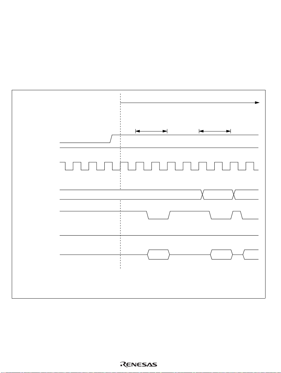
Reset exception handling takes place as follows.
• The CPU internal state and the registers of on-chip peripheral modules are initialized, with the
I bit of the condition code register (CCR) set to 1.
• The PC is loaded from the reset exception handling vector address (H'0000 to H'0001), after
which the program starts executing from the address indicated in PC.
When system power is turned on or off, the RES pin should be held low.
Figures 3.1 and 3.2 show the reset sequence.
Reset cleared
Program initial
instruction prefetch
RES
MD0
φ
High
Vector fetch
Internal
processing
Internal
address bus
Internal read
signal
Internal write
signal
Internal data
bus (16-bit)
64
(1)
(2) (3)
(1) Reset exception handling vector address (H'0000)
(2) Program start address
(3) First instruction of program
Figure 3.1 Reset Sequence (when MD0 Pin is High)
(2)
Page 80

RES
MD0
φ
8,192 clock
cycles
Vector fetch
Reset cleared
Internal
processing
Program initial
instruction prefetch
Internal
address bus
Internal read
signal
Internal write
signal
Internal data
bus (16-bit)
(1)
(2) (3)
(1) Reset exception handling vector address (H'0000)
(2) Program start address
(3) First instruction of program
(2)
Figure 3.2 Reset Sequence (when MD0 Pin is Low)
3.2.3 Interrupt Immediately after Reset
After a reset, if an interrupt were to be accepted before the stack pointer (SP: R7) was initialized,
PC and CCR would not be pushed onto the stack correctly, resulting in program runaway. To
prevent this, immediately after reset exception handling all interrupts are masked. For this reason,
the initial program instruction is always executed immediately after a reset. This instruction should
initialize the stack pointer (e.g. MOV.W #xx: 16, SP).
65
Page 81

3.3 Interrupts
3.3.1 Overview
The interrupt sources include 13 external interrupts (WKP0 to WKP7, IRQ0 to IRQ4), and 20
internal interrupts from on-chip peripheral modules. Table 3.2 shows the interrupt sources, their
priorities, and their vector addresses. When more than one interrupt is requested, the interrupt with
the highest priority is processed.
The interrupts have the following features:
• Both internal and external interrupts can be masked by the I bit of CCR. When this bit is set to
1, interrupt request flags are set but interrupts are not accepted.
• The external interrupt pins IRQ0 to IRQ4 can each be set independently to either rising edge
sensing or falling edge sensing.
Table 3.2 Interrupt Sources and Priorities
Vector
Priority Interrupt Source Interrupt
High RES Reset 0 H'0000 to H'0001
IRQ
IRQ
IRQ
IRQ
IRQ
WKP
WKP
WKP
WKP
WKP
WKP
WKP
WKP
0
1
2
3
4
0
1
2
3
4
5
6
7
IRQ
IRQ
IRQ
IRQ
IRQ
WKP
WKP
WKP
WKP
WKP
WKP
WKP
WKP
0
1
2
3
4
0
1
2
3
4
5
6
7
SCI1 SCI1 transfer complete 10 H'0014 to H'0015
Timer A Timer A overflow 11 H'0016 to H'0017
Timer B Timer B overflow 12 H'0018 to H'0019
Low Timer C Timer C overflow or underflow 13 H'001A to H'001B
Number Vector Address
4 H'0008 to H'0009
5 H'000A to H'000B
6 H'000C to H'000D
7 H'000E to H'000F
8 H'0010 to H'0011
9 H'0012 to H'0013
66
Page 82

Table 3.2 Interrupt Sources and Priorities (cont)
Vector
Priority Interrupt Source Interrupt
High Timer FL Timer FL compare match 14 H'001C to H'001D
Timer FL overflow
Timer FH Timer FH compare match 15 H'001E to H'001F
Timer FH overflow
Timer G Timer G input capture 16 H'0020 to H'0021
Timer G overflow
SCI2 SCI2 transfer complete 17 H'0022 to H'0023
SCI2 transfer abort
SCI3 SCI3 transmit end 18 H'0024 to H'0025
SCI3 transmit data empty
SCI3 receive data full
SCI3 overrun error
SCI3 framing error
SCI3 parity error
A/D converter A/D conversion end 19 H'0026 to H'0027
(SLEEP instruction
Low
Note: Vector addresses H'0002 to H'0007 are reserved and cannot be used.
executed)
Direct transfer 20 H'0028 to H'0029
Number Vector Address
3.3.2 Interrupt Control Registers
Table 3.3 lists the registers that control interrupts.
Table 3.3 Interrupt Control Registers
Register Name Abbreviation R/W Initial Value Address
IRQ edge select register IEGR R/W H'E0 H'FFF2
Interrupt enable register 1 IENR1 R/W H'00 H'FFF3
Interrupt enable register 2 IENR2 R/W H'00 H'FFF4
Interrupt request register 1 IRR1 R/W* H'20 H'FFF6
Interrupt request register 2 IRR2 R/W* H'00 H'FFF7
Wakeup interrupt request register IWPR R/W* H'00 H'FFF9
Note: *Write is enabled only for writing of 0 to clear a flag.
67
Page 83

IRQ Edge Select Register (IEGR)
Bit 76543210
— — — IEG4 IEG3 IEG2 IEG1 IEG0
Initial value 11100000
Read/Write — — — R/W R/W R/W R/W R/W
IEGR is an 8-bit read/write register, used to designate whether pins IRQ0 to IRQ4 are set to rising
edge sensing or falling edge sensing.
Bits 7 to 5—Reserved Bits: Bits 7 to 5 are reserved; they are always read as 1, and cannot be
modified.
Bit 4—IRQ4 Edge Select (IEG4): Bit 4 selects the input sensing of pin IRQ4/ADTRG.
Bit 4: IEG4 Description
0 Falling edge of IRQ
/ADTRG pin input is detected (initial value)
4
1 Rising edge of IRQ4/ADTRG pin input is detected
Bit 3—IRQ3 Edge Select (IEG3): Bit 3 selects the input sensing of pin IRQ3/TMIF.
Bit 3: IEG3 Description
0 Falling edge of IRQ
1 Rising edge of IRQ3/TMIF pin input is detected
/TMIF pin input is detected (initial value)
3
Bit 2—IRQ2 Edge Select (IEG2): Bit 2 selects the input sensing of pin IRQ2/TMIC.
Bit 2: IEG2 Description
0 Falling edge of IRQ
/TMIC pin input is detected (initial value)
2
1 Rising edge of IRQ2/TMIC pin input is detected
Bit 1—IRQ1 Edge Select (IEG1): Bit 1 selects the input sensing of pin IRQ1/TMIB.
Bit 1: IEG1 Description
0 Falling edge of IRQ
1 Rising edge of IRQ1/TMIB pin input is detected
68
/TMIB pin input is detected (initial value)
1
Page 84

Bit 0—IRQ0 Edge Select (IEG0): Bit 0 selects the input sensing of pin IRQ0.
Bit 0: IEG0 Description
0 Falling edge of IRQ
pin input is detected (initial value)
0
1 Rising edge of IRQ0 pin input is detected
Interrupt Enable Register 1 (IENR1)
Bit 76543210
IENTA IENS1 IENWP IEN4 IEN3 IEN2 IEN1 IEN0
Initial value 00000000
Read/Write R/W R/W R/W R/W R/W R/W R/W R/W
IENR1 is an 8-bit read/write register that enables or disables interrupt requests.
Bit 7—Timer A Interrupt Enable (IENTA): Bit 7 enables or disables timer A overflow interrupt
requests.
Bit 7: IENTA Description
0 Disables timer A interrupts (initial value)
1 Enables timer A interrupts
Bit 6—SCI1 Interrupt Enable (IENS1): Bit 6 enables or disables SCI1 transfer complete
interrupt requests.
Bit 6: IENS1 Description
0 Disables SCI1 interrupts (initial value)
1 Enables SCI1 interrupts
Bit 5—Wakeup Interrupt Enable (IENWP): Bit 5 enables or disables WKP7 to WKP0 interrupt
requests.
Bit 5: IENWP Description
0 Disables interrupt requests from WKP
to WKP
7
1 Enables interrupt requests from WKP7 to WKP
0
0
(initial value)
69
Page 85

Bits 4 to 0—IRQ4 to IRQ0 Interrupt Enable (IEN4 to IEN0): Bits 4 to 0 enable or disable IRQ
to IRQ0 interrupt requests.
Bit n: IENn Description
0 Disables interrupt request IRQn (initial value)
1 Enables interrupt request IRQn
(n = 4 to 0)
Interrupt Enable Register 2 (IENR2)
Bit 76543210
IENDT IENAD IENS2 IENTG IENTFH IENTFL IENTC IENTB
Initial value 00000000
Read/Write R/W R/W R/W R/W R/W R/W R/W R/W
IENR2 is an 8-bit read/write register that enables or disables interrupt requests.
Bit 7—Direct Transfer Interrupt Enable (IENDT): Bit 7 enables or disables direct transfer
interrupt requests.
Bit 7: IENDT Description
0 Disables direct transfer interrupt requests (initial value)
1 Enables direct transfer interrupt requests
4
Bit 6—A/D Converter Interrupt Enable (IENAD): Bit 6 enables or disables A/D converter
interrupt requests.
Bit 6: IENAD Description
0 Disables A/D converter interrupt requests (initial value)
1 Enables A/D converter interrupt requests
Bit 5—SCI2 Interrupt Enable (IENS2): Bit 5 enables or disables SCI2 transfer complete and
transfer abort interrupt requests.
Bit 5: IENS2 Description
0 Disables SCI2 interrupts (initial value)
1 Enables SCI2 interrupts
70
Page 86

Bit 4—Timer G Interrupt Enable (IENTG): Bit 4 enables or disables timer G input capture and
overflow interrupt requests.
Bit 4: IENTG Description
0 Disables timer G interrupts (initial value)
1 Enables timer G interrupts
Bit 3—Timer FH Interrupt Enable (IENTFH): Bit 3 enables or disables timer FH compare
match and overflow interrupt requests.
Bit 3: IENTFH Description
0 Disables timer FH interrupts (initial value)
1 Enables timer FH interrupts
Bit 2—Timer FL Interrupt Enable (IENTFL): Bit 2 enables or disables timer FL compare
match and overflow interrupt requests.
Bit 2: IENTFL Description
0 Disables timer FL interrupts (initial value)
1 Enables timer FL interrupts
Bit 1—Timer C Interrupt Enable (IENTC): Bit 1 enables or disables timer C overflow or
underflow interrupt requests.
Bit 1: IENTC Description
0 Disables timer C interrupts (initial value)
1 Enables timer C interrupts
Bit 0—Timer B Interrupt Enable (IENTB): Bit 0 enables or disables timer B overflow or
underflow interrupt requests.
Bit 0: IENTB Description
0 Disables timer B interrupts (initial value)
1 Enables timer B interrupts
SCI3 interrupt control is covered in 10.4.2, in the description of serial control register 3.
71
Page 87

Interrupt request register 1 (IRR1)
Bit 76543210
IRRTA IRRS1 — IRRI4 IRRI3 IRRI2 IRRI1 IRRI0
Initial value 00100000
Read/Write R/W* R/W* — R/W* R/W* R/W* R/W* R/W*
Note: *Only a write of 0 for flag clearing is possible.
IRR1 is an 8-bit read/write register, in which the corresponding bit is set to 1 when a timer A,
SCI1, or IRQ4 to IRQ0 interrupt is requested. The flags are not cleared automatically when an
interrupt is accepted. It is necessary to write 0 to clear each flag.
Bit 7—Timer A Interrupt Request Flag (IRRTA)
Bit 7: IRRTA Description
0 Clearing conditions:
When IRRTA = 1, it is cleared by writing 0 (initial value)
1 Setting conditions:
When the timer A counter value overflows (goes from H'FF to H'00)
Bit 6—SCI1 Interrupt Request Flag (IRRS1)
Bit 6: IRRS1 Description
0 Clearing conditions:
When IRRS1 = 1, it is cleared by writing 0 (initial value)
1 Setting conditions:
When an SCI1 transfer is completed
Bit 5—Reserved Bit: Bit 5 is reserved; it is always read as 1, and cannot be modified.
Bits 4 to 0—IRQ4 to IRQ0 Interrupt Request Flags (IRRI4 to IRRI0)
Bit n: IRRIn Description
0 Clearing conditions:
When IRRIn = 1, it is cleared by writing 0 to IRRIn (initial value)
1 Setting conditions:
IRRIn is set when pin IRQ
edge is detected
72
is set to interrupt input, and the designated signal
n
(n = 4 to 0)
Page 88

Interrupt Request Register 2 (IRR2)
Bit 76543210
IRRDT IRRAD IRRS2 IRRTG IRRTFH IRRTFL IRRTC IRRTB
Initial value 00000000
Read/Write R/W* R/W* R/W* R/W* R/W* R/W* R/W* R/W*
Note: *Only a write of 0 for flag clearing is possible.
IRR2 is an 8-bit read/write register, in which the corresponding bit is set to 1 when a direct
transfer, A/D converter, SCI2, timer G, timer FH, timer FL, timer C, or timer B interrupt is
requested. The flags are not cleared automatically when an interrupt is accepted. It is necessary to
write 0 to clear each flag.
Bit 7—Direct Transfer Interrupt Request Flag (IRRDT)
Bit 7: IRRDT Description
0 Clearing conditions:
When IRRDT = 1, it is cleared by writing 0 (initial value)
1 Setting conditions:
When DTON = 1 and a direct transfer is made immediately after a SLEEP
instruction is executed
Bit 6—A/D Converter Interrupt Request Flag (IRRAD)
Bit 6: IRRAD Description
0 Clearing conditions:
When IRRAD = 1, it is cleared by writing 0 (initial value)
1 Setting conditions:
When A/D conversion is completed and ADSF is reset
Bit 5—SCI2 Interrupt Request Flag (IRRS2)
Bit 5: IRRS2 Description
0 Clearing conditions:
When IRRS2 = 1, it is cleared by writing 0 (initial value)
1 Setting conditions:
When an SCI2 transfer is completed or aborted
73
Page 89

Bit 4—Timer G Interrupt Request Flag (IRRTG)
Bit 4: IRRTG Description
0 Clearing conditions:
When IRRTG = 1, it is cleared by writing 0 (initial value)
1 Setting conditions:
When pin TMIG is set to TMIG input and the designated signal edge is
detected
Bit 3—Timer FH Interrupt Request Flag (IRRTFH)
Bit 3: IRRTFH Description
0 Clearing conditions:
When IRRTFH = 1, it is cleared by writing 0 (initial value)
1 Setting conditions:
When counter FH matches output compare register FH in 8-bit timer mode, or
when 16-bit counter F (TCFL, TCFH) matches output compare register F
(OCRFL, OCRFH) in 16-bit timer mode
Bit 2—Timer FL Interrupt Request Flag (IRRTFL)
Bit 2: IRRTFL Description
0 Clearing conditions:
When IRRTFL = 1, it is cleared by writing 0 (initial value)
1 Setting conditions:
When counter FL matches output compare register FL in 8-bit timer mode
Bit 1—Timer C Interrupt Request Flag (IRRTC)
Bit 1: IRRTC Description
0 Clearing conditions:
When IRRTC = 1, it is cleared by writing 0 (initial value)
1 Setting conditions:
When the timer C counter value overflows (goes from H'FF to H'00) or
underflows (goes from H'00 to H'FF)
74
Page 90

Bit 0—Timer B Interrupt Request Flag (IRRTB)
Bit 0: IRRTB Description
0 Clearing conditions:
When IRRTB = 1, it is cleared by writing 0 (initial value)
1 Setting conditions:
When the timer B counter value overflows (goes from H'FF to H'00)
Wakeup Interrupt Request Register (IWPR)
Bit 76543210
IWPF7 IWPF6 IWPF5 IWPF4 IWPF3 IWPF2 IWPF1 IWPF0
Initial value 00000000
Read/Write R/W* R/W* R/W* R/W* R/W* R/W* R/W* R/W*
Note: *Only a write of 0 for flag clearing is possible.
IWPR is an 8-bit read/write register, in which the corresponding bit is set to 1 when pins WKP7 to
WKP0 are set to wakeup input and a pin receives a falling edge input. The flags are not cleared
automatically when an interrupt is accepted. It is necessary to write 0 to clear each flag.
Bits 7 to 0—Wakeup Interrupt Request Flags (WKPF7 to WKPF0)
Bit n: IWPFn Description
0 Clearing conditions:
When IWPFn = 1, it is cleared by writing 0 to IWPFn
1 Setting conditions:
IWPFn is set when pin WKP
input is detected at the pin
is set to wakeup interrupt input, and a falling edge
n
(n = 7 to 0)
3.3.3 External Interrupts
There are 13 external interrupts, WKP0 to WKP7 and IRQ0 to IRQ4.
Interrupts WKP0 to WKP7: Interrupts WKP0 to WKP7 are requested by falling edge inputs at
pins WKP0 to WKP7. When these pins are designated as WKP0 to WKP7 pins in port mode register
5 (PMR5) and falling edge input is detected, the corresponding bit in the wakeup interrupt request
register (IWPR) is set to 1, requesting an interrupt. Wakeup interrupt requests can be disabled by
clearing the IENWP bit in IENR1 to 0. It is also possible to mask all interrupts by setting the CCR
I bit to 1.
75
Page 91

When an interrupt exception handling request is received for interrupts WKP0 to WKP7, the CCR I
bit is set to 1. The vector number for interrupts WKP0 to WKP7 is 9. Since all eight interrupts are
assigned the same vector number, the interrupt source must be determined by the exception
handling routine.
Interrupts IRQ0 to IRQ4: Interrupts IRQ0 to IRQ4 are requested by into pins inputs to IRQ0 to
IRQ4. These interrupts are detected by either rising edge sensing or falling edge sensing,
depending on the settings of bits IEG0 to IEG4 in the edge select register (IEGR).
When these pins are designated as pins IRQ0 to IRQ4 in port mode registers 1 and 2 (PMR1 and
PMR2) and the designated edge is input, the corresponding bit in IRR1 is set to 1, requesting an
interrupt. Interrupts IRQ0 to IRQ4 can be disabled by clearing bits IEN0 to IEN4 in IENR1 to 0.
All interrupts can be masked by setting the I bit in CCR to 1.
When IRQ0 to IRQ4 interrupt exception handling is initiated, the I bit is set to 1. Vector numbers 4
to 8 are assigned to interrupts IRQ0 to IRQ4. The order of priority is from IRQ0 (high) to IRQ
4
(low). Table 3.2 gives details.
3.3.4 Internal Interrupts
There are 20 internal interrupts that can be requested by the on-chip peripheral modules. When a
peripheral module requests an interrupt, the corresponding bit in IRR1 or IRR2 is set to 1.
Individual interrupt requests can be disabled by clearing the corresponding bit in IENR1 or IENR2
to 0. All interrupts can be masked by setting the I bit in CCR to 1. When an internal interrupt
request is accepted, the I bit is set to 1. Vector numbers 10 to 20 are assigned to these interrupts.
Table 3.2 shows the order of priority of interrupts from on-chip peripheral modules.
3.3.5 Interrupt Operations
Interrupts are controlled by an interrupt controller. Figure 3.3 shows a block diagram of the
interrupt controller. Figure 3.4 shows the flow up to interrupt acceptance.
Interrupt operation is described as follows.
• When an interrupt condition is met while the interrupt enable register bit is set to 1, an
interrupt request signal is sent to the interrupt controller.
• When the interrupt controller receives an interrupt request, it sets the interrupt request flag.
• From among the interrupts with interrupt request flags set to 1, the interrupt controller selects
the interrupt request with the highest priority and holds the others pending. (Refer to
table 3.2 for a list of interrupt priorities.)
• The interrupt controller checks the I bit of CCR. If the I bit is 0, the selected interrupt request is
accepted; if the I bit is 1, the interrupt request is held pending.
76
Page 92

• If the interrupt is accepted, after processing of the current instruction is completed, both PC
and CCR are pushed onto the stack. The state of the stack at this time is shown in figure 3.5.
The PC value pushed onto the stack is the address of the first instruction to be executed upon
return from interrupt handling.
• The I bit of CCR is set to 1, masking all further interrupts.
• The vector address corresponding to the accepted interrupt is generated, and the interrupt
handling routine located at the address indicated by the contents of the vector address is
executed.
Notes: 1. When disabling interrupts by clearing bits in an interrupt enable register, or when
clearing bits in an interrupt request register, always do so while interrupts are masked
(I = 1).
2. If the above clear operations are performed while I = 0, and as a result a conflict arises
between the clear instruction and an interrupt request, exception processing for the
interrupt will be executed after the clear instruction has been executed.
Interrupt controller
External or
internal
interrupts
Interrupt
request
External
interrupts or
internal
interrupt
enable
signals
Priority decision logic
CCR (CPU)I
Figure 3.3 Block Diagram of Interrupt Controller
77
Page 93

Program execution state
IRRIO = 1
Yes
IENO = 1
Yes
I = 0
No
No
No
IRRI1 = 1
Yes
IEN1 = 1
Yes
No
No
IRRI2 = 1
Yes
IEN2 = 1
Yes
No
No
IRRDT = 1
IENDT = 1
No
Yes
No
Yes
CCR contents saved
Notation:
PC:
Program counter
CCR:
Condition code register
I:
I bit of CCR
78
Yes
PC contents saved
I ← 1
Branch to interrupt
handling routine
Figure 3.4 Flow up to Interrupt Acceptance
Page 94

SP – 4
SP – 3
SP – 2
SP – 1
SP (R7)
Stack area
SP (R7)
SP + 1
SP + 2
SP + 3
SP + 4
CCR
CCR*
PC
PC
H
L
Even address
Prior to start of interrupt
exception handling
PC and CCR
saved to stack
After completion of interrupt
exception handling
Notation:
Upper 8 bits of program counter (PC)
PC
:
H
Lower 8 bits of program counter (PC)
PC
:
L
Condition code register
CCR:
Stack pointer
SP:
1.2.PC shows the address of the first instruction to be executed upon
Notes:
return from the interrupt handling routine.
Register contents must always be saved and restored by word access,
starting from an even-numbered address.
* Ignored on return from interrupt.
Figure 3.5 Stack State after Completion of Interrupt Exception Handling
Figure 3.6 shows a typical interrupt sequence where the program area is in the on-chip ROM and
the stack area is in the on-chip RAM.
79
Page 95

Prefetch instruction of
interrupt-handling routine
Internal
processing
Vector fetch
Stack access
Internal
processing
Instruction
prefetch
(9)
(3) (9)(8)(6)(5)
(4) (1) (7) (10)
80
Interrupt is
accepted
Interrupt level
decision and wait for
end of instruction
Interrupt
request signal
(1)
φ
Internal
address bus
Internal read
signal
Internal write
signal
Figure 3.6 Interrupt Sequence
(2)
Internal data bus
(16 bits)
(1) Instruction prefetch address (Instruction is not executed. Address is saved as PC contents, becoming return address.)
(2)(4) Instruction code (not executed)
(3) Instruction prefetch address (Instruction is not executed.)
(5) SP – 2
(6) SP – 4
(7) CCR
(8) Vector address
(9) Starting address of interrupt-handling routine (contents of vector address)
(10) First instruction of interrupt-handling routine
Page 96

3.3.6 Interrupt Response Time
Table 3.4 shows the number of wait states after an interrupt request flag is set until the first
instruction of the interrupt handler is executed.
Table 3.4 Interrupt Wait States
Item States
Waiting time for completion of executing instruction* 1 to 13
Saving of PC and CCR to stack 4
Vector fetch 2
Instruction fetch 4
Internal processing 4
Total 15 to 27
Note: *Not including EEPMOV instruction.
3.4 Application Notes
3.4.1 Notes on Stack Area Use
When word data is accessed in the H8/3834 Series, the least significant bit of the address is
regarded as 0. Access to the stack always takes place in word size, so the stack pointer (SP: R7)
should never indicate an odd address. Use PUSH Rn (MOV.W Rn, @–SP) or POP Rn (MOV.W
@SP+, Rn) to save or restore register values.
Setting an odd address in SP may cause a program to crash. An example is shown in figure 3.7.
81
Page 97

SP
→
SP
→
PC
PC
→
H
L
SP
R1L
PC
H'FEFC
L
H'FEFD
H'FEFF
BSR instruction
SP set to H'FEFF Stack accessed beyond SP
Notation:
Upper byte of program counter
PC
:
H
Lower byte of program counter
PC
:
L
General register R1L
R1L:
Stack pointer
SP:
MOV. B R1L, @–R7
Contents of PC are lost
H
Figure 3.7 Operation when Odd Address is Set in SP
When CCR contents are saved to the stack during interrupt exception handling or restored when
RTE is executed, this also takes place in word size. Both the upper and lower bytes of word data
are saved to the stack; on return, the even address contents are restored to CCR while the odd
address contents are ignored.
3.4.2 Notes on Rewriting Port Mode Registers
When a port mode register is rewritten to switch the functions of external interrupt pins, the
following points should be observed.
When an external interrupt pin function is switched by rewriting the port mode register that
controls these pins (IRQ4 to IRQ0, and WKP7 to WKP0), the interrupt request flag may be set to 1
at the time the pin function is switched, even if no valid interrupt is input at the pin. Be sure to
clear the interrupt request flag to 0 after switching pin functions. Table 3.5 shows the conditions
under which interrupt request flags are set to 1 in this way.
82
Page 98

Table 3.5 Conditions under which Interrupt Request Flag is Set to 1
Interrupt Request
Flags Set to 1 Conditions
IRR1 IRRI4
IRRI3
IRRI2
IRRI1
IRRI0
IWPR IWPF7 When PMR5 bit WKP7 is changed from 0 to 1 while pin WKP7 is low
IWPF6 When PMR5 bit WKP6 is changed from 0 to 1 while pin WKP6 is low
IWPF5 When PMR5 bit WKP5 is changed from 0 to 1 while pin WKP5 is low
IWPF4 When PMR5 bit WKP4 is changed from 0 to 1 while pin WKP4 is low
IWPF3 When PMR5 bit WKP3 is changed from 0 to 1 while pin WKP3 is low
IWPF2 When PMR5 bit WKP2 is changed from 0 to 1 while pin WKP2 is low
IWPF1 When PMR5 bit WKP1 is changed from 0 to 1 while pin WKP1 is low
IWPF0 When PMR5 bit WKP0 is changed from 0 to 1 while pin WKP0 is low
• When PMR2 bit IRQ4 is changed from 0 to 1 while pin IRQ
IEGR bit IEG4 = 0.
• When PMR2 bit IRQ4 is changed from 1 to 0 while pin IRQ
IEGR bit IEG4 = 1.
• When PMR1 bit IRQ3 is changed from 0 to 1 while pin IRQ
IEGR bit IEG3 = 0.
• When PMR1 bit IRQ3 is changed from 1 to 0 while pin IRQ
IEGR bit IEG3 = 1.
• When PMR1 bit IRQ2 is changed from 0 to 1 while pin IRQ
IEGR bit IEG2 = 0.
• When PMR1 bit IRQ2 is changed from 1 to 0 while pin IRQ
IEGR bit IEG2 = 1.
• When PMR1 bit IRQ1 is changed from 0 to 1 while pin IRQ
IEGR bit IEG1 = 0.
• When PMR1 bit IRQ1 is changed from 1 to 0 while pin IRQ
IEGR bit IEG1 = 1.
• When PMR2 bit IRQ0 is changed from 0 to 1 while pin IRQ
IEGR bit IEG0 = 0.
• When PMR2 bit IRQ0 is changed from 1 to 0 while pin IRQ
IEGR bit IEG0 = 1.
is low and
4
is low and
4
is low and
3
is low and
3
is low and
2
is low and
2
is low and
1
is low and
1
is low and
0
is low and
0
83
Page 99

Figure 3.8 shows the procedure for setting a bit in a port mode register and clearing the interrupt
request flag.
When switching a pin function, mask the interrupt before setting the bit in the port mode register.
After accessing the port mode register, execute at least one instruction (e.g., NOP), then clear the
interrupt request flag from 1 to 0. If the instruction to clear the flag is executed immediately after
the port mode register access without executing an intervening instruction, the flag will not be
cleared.
An alternative method is to avoid the setting of interrupt request flags when pin functions are
switched by keeping the pins at the high level so that the conditions in table 3.5 do not occur.
Interrupts masked. (Another possibility
CCR I bit 1
Set port mode register bit
Execute NOP instruction
Clear interrupt request flag to 0
←
is to disable the relevant interrupt in
interrupt enable register 1.)
After setting the port mode register bit,
first execute at least one instruction
(e.g., NOP), then clear the interrupt
request flag to 0
CCR I bit 0
←
Interrupt mask cleared
Figure 3.8 Port Mode Register Setting and Interrupt Request Flag Clearing Procedure
84
Page 100

Section 4 Clock Pulse Generators
4.1 Overview
Clock oscillator circuitry (CPG: clock pulse generator) is provided on-chip, including both a
system clock pulse generator and a subclock pulse generator. The system clock pulse generator
consists of a system clock oscillator and system clock dividers. The subclock pulse generator
consists of a subclock oscillator circuit and a subclock divider.
4.1.1 Block Diagram
Figure 4.1 shows a block diagram of the clock pulse generators.
φ
/2
OSC
System clock
divider (1/8)
φ
/2
W
/4
φ
W
φ
/8
W
/16
φ
OSC
φ
Prescaler S
(13 bits)
φ
SUB
Prescaler W
(5 bits)
φ
/2
to
φ
/8192
φ
φ
/2
φ
/4
/8
φ
to
φ
/128
OSC
OSC
1
System clock
2
X
1
X
2
oscillator
System clock pulse generator
Subclock
oscillator
Subclock pulse generator
φ
OSC
(f )
OSC
φ
W
(f )
W
System clock
divider (1/2)
Subclock
divider
(1/2, 1/4, 1/8)
W
W
W
W
W
Figure 4.1 Block Diagram of Clock Pulse Generators
4.1.2 System Clock and Subclock
The basic clock signals that drive the CPU and on-chip peripheral modules are φ and
the clock signals have names: φ is the system clock,
clock, and
φ
is the watch clock.
W
φ
is the subclock,
SUB
φ
is the oscillator
OSC
φ
SUB
. Four of
The clock signals available for use by peripheral modules are φ/2, φ/4, φ/8, φ/16, φ/32, φ/64,
φ
/128, φ/256, φ/512, φ/1024, φ/2048, φ/4096, φ/8192,
and
φ
/128. The clock requirements differ from one module to another.
W
φ
,
φ
/2,
φ
/4,
φ
/8,
φ
/16,
φ
W
W
W
W
W
W
/32,
φ
/64,
W
85
 Loading...