

Page 1

Steuergerät
6
RCA / Cinch Kabel
REN10/20/35KIT
Verstärker
EINBAUANLEITUNG
2-KANAL VERSTÄRKER
Massekabel
2
7
Steuerleitung
Bitte befolgen Sie die folgenden Hinweise:
Entfernen Sie als erstes das Massekabel des Minuspols der Fahrzeugbatterie.
1
Verbinden Sie das Massekabel (braun, 0.8m) mit dem Masseanschluss des Verstärkers und einem geeigneten
2
Massepunkt am Fahrzeugchassis, mit einer maximalen Entfernung von einem Meter vom Verstärker. Benutzen Sie
den Kabelschuh für den Anschluss am Massepunkt. Achten Sie darauf, dass Farbe und Isolierung um den
Massepunkt ausreichend entfernt wurde.
Finden Sie eine geeignete Position für den Sicherungshalter in der Nähe der Fahrzeugbatterie. Die Entfernung darf
3
nicht mehr als 30 cm betragen. Bitte keine Teile des Fahrzeugs, wie Kraftstoffleitungen, Kabel usw. beschädigen.
Trennen Sie ein Teil der Stromleitung (rot, 5 m) am Ende ab, das die selbe Länge wie die Distanz zwischen Batterie
4
und Sicherungshalter besitzt (max. 30 cm). Verbinden Sie das Ende des anderen Teilstücks mit dem
Sicherungshalter (ohne eingelegte Sicherung) und dann das Ende des Teilstücks mit dem Pluspol der Batterie.
Verwenden Sie zum Anschluss die mitgelieferten Kabelschuhe.
Dann führen Sie den Rest der Stromleitung (rot) vom Bereich der Fahrzeugbatterie durch das Fahrzeug zum +12V
5
Anschluss des Verstärkers und schließen dies dort an. Verbinden Sie dann das andere Ende des Kabels mit dem
Sicherungshalter am vorgesehenen Anschluss.
Führen Sie dann das RCA/CINCH Kabel mit der Steuerleitung (blau, 5m) vom Steuergerät zur Position des
6
Verstärkers. Verbinden Sie dann die RCA/CINCH Stecker an einem Ende mit dem Verstärker und die des anderen
Endes mit der Steuereinheit. Bitte achten Sie auf die korrekte Polung der Anschlüsse.
Verbinden Sie ein Ende der Steuerleitung (blau, 5m) mit dem REMOTE/REM-Anschluss der Steuereinheit und das
7
andere Ende mit dem REMOTE/REM Anschluss des Verstärkers. Diese Leitung leitet das An-/Aus-Signal des
Steuergeräts zum Verstärker.
Zuletzt setzen Sie die Sicherung in den Sicherungshalter. Achten Sie darauf keinen Kurzschluss zu verursachen,
8
dies kann die Fahrzeug-Elektrik ernsthaft beschädigen. Berühren Sie keine blanken Metallteile an den Kabeln oder
der Batterie, andernfalls besteht die Gefahr eines elektrischen Schlages. Schließen Sie dann das zuvor entfernte
Massekabel wieder an den Minuspol der Fahrzeugbatterie.
Wenn Sie die oben genannten Hinweise befolgt haben, ist Ihr Car Audio System betriebsbereit. Befolgen Sie dann
die Instruktionen der Bedienungsanleitung Ihres Verstärkers oder der Steuereinheit.
7
WICHTIGE HINWEISE:
- Befolgen Sie auf jeden Fall die Anweisungen links.
- Beschädigen Sie keine Teile des Fahrzeugs, wie den
Tank, Leitungen, Airbags usw.
- Knicken Sie oder spleißen Sie keine Kabel oder Leitungen.
- Berühren Sie keine blanken Metallflächen der Stromleitung
oder der Batterie.
- Achten Sie stets auf die korrekte Polung aller Anschlüsse.
- Vermeiden Sie Kurzschlüsse.
- Wenden Sie sich bei Fragen und Problemen an Ihren
Fachhändler oder Ihre KFZ-Werkstatt
- Tauschen Sie defekte Sicherungen nur gegen solche aus,
die den gleichen Sicherungswert besitzen:
REN10KIT 40A AGU
REN20KIT 60A AGU
REN35KIT 100A ANL
REM
5
Stromkabel +12V
FUSE
Sicherungshalter
3
4
1
Fahrzeugbatterie
Chassis
Teilstück
Page 2
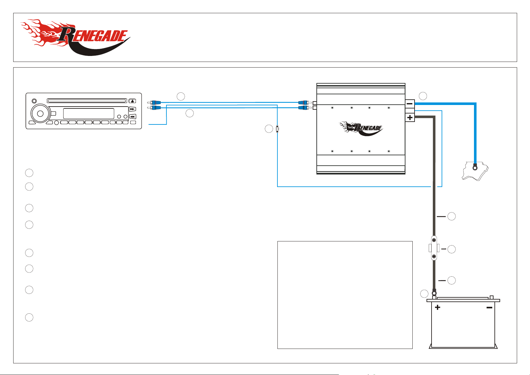
Head unit
6
RCA / Cinch Cable
INSTALLATION GUIDE
Amplifier
REN10/20/35KIT
2-CHANNEL AMPLIFIERS
Ground Cable
2
7
Remote Wire
Please attend the following instructions:
Disconnect at first the negative ground connection from the vehicle’s battery.
1
Connect the GROUND CABLE (brown, 0.8m) with the ground terminal of the amplifier and a suitable GROUND contact
2
point on the car chassis, with a maximum distance of 1 meter from the amplifier. Use the ringterminal for the GROUND
contact point. Ensure that all paint or other insulation is removed from around the hole area.
Find a suitable position for the FUSE HOLDER next to the car battery’s PLUS POLE. The maximum distance should
3
not be more than 30 cm. Please ensure, that you don’t damage any parts of the car, like the fuel tank, wires etc.
Cut off a part of the POWER CABLE (red, 5m) on one end, which has the same length like the distance from the
4
battery’s PLUS POLE to the FUSE HOLDER (max. 30cm). Connect this part on the end without ringterminal with the
FUSE HOLDER (without inserted fuse) and the other end to the battery’s PLUS POLE. Use for the connection the
supplied ring terminals.
Lead one end of the POWER CABLE (red) from the car battery area through the car to the +12V terminal of the
5
amplifier and connect it. Then connect the other end of the cable with the FUSE HOLDER at the suitable terminal.
Lead the RCA/CINCH CABLE pair with attached REMOTE WIRE from the HEAD UNIT through the car to the
6
amplifier’s position. Then connect the RCA/CINCH plugs on one end with amplifier, and the other end with the HEAD
UNIT RCA/CINCH outputs. Please observe the correct polarity of all connections.
Connect the one end of the attached REMOTE WIRE with the REMOTE/REM terminal of the HEAD UNIT and the
7
other end with the REMOTE/REM terminal of the amplifier. This wire provides a turn on/turn off signal to the amplifier,
when the HEAD UNIT is turned on / turned off. NOTE: some amplifier types may require, that you have to extend the
REMOTE WIRE with a suitable cable, to lead the REMOTE WIRE to the other endpanel of the amplifier.
At least insert the FUSE into the FUSE HOLDER. Ensure not to cause a short circuit, or your car’s electric system
8
may get damaged. Do not touch the bare metal parts of the cable or the car battery, otherwise a risk of electric shock
consists. Then re-connect the negative ground connection to the vehicle’s battery.
If you have followed all instructions above, your car audio system is ready for operation. Then follow the further
instructions of the OWNER’S MANUALS of your amplifier and your head unit.
7
IMPORTANT NOTES:
- Follow by any means the instructions on the left.
- Do not damage any parts of the car like the
fuel tank, electronic system, airbags etc.
- Do not bend or splice any wires or cables.
- Do not touch any bare metal parts of the power cable or
the vehicle’s battery.
- Ensure always the correct polarity of all connections.
- Avoid any short circuits.
- Consult your retailer or car service station in case of open
question or problems.
- Replace the fuse in the fuse holder only with spare
fuses of the same value:
REN10KIT 40A AGU
REN20KIT 60A AGU
REN35KIT 100A ANL
REM
Chassis
5
Power Cable
FUSE
Fuse Holder
3
Cut-off Part
4
1
Battery
 Loading...