


Frequently Asked Questions (FAQ)
3.0
300
150
1.5
400200600
0
Time (hrs.)
Voltage (V)
Internal resistance (Ohm)
Voltage
Internal resistance
General electrical performance
Which values of open circuit voltage do
ithium cells typically show?
l
The CR-type coin cells, based on the lithium/
anganese dioxide electrochemical system, have
m
a nominal voltage of 3 V. In practice, a fresh
lithium cell will typically show an OCV (Open
Circuit Voltage) between 3.10-3.40 V. This range
of values is intended for measurements
performed at room temperature; in fact, the OCV
values depend on the temperature of the
measurement.
After storage periods the cells may also show
values outside this range, due to ageing effects
(see the recommended storage conditions for
lithium coin cells, also reported in this document).
What is the internal resistance of a cell?
How does it affect the performance of the
cell?
From an electrical point of view, a cell is a
combination of an energy source and a
resistance. The internal resistance (Ri) is a key
parameter for a cell, as it determines its highpower capability (i.e. its ability of delivering its
energy in a short time). The internal resistance
reduces the useful voltage in applications and
leads to internal heat, thus loss of energy, which
increases with the square of the current.
The internal resistance of lithium cell is a sum of
both ohmic contributions and of resistive
contributions coming from electrochemical
phenomena taking place during the discharge of
the cell. By accurate selection and quality control
of materials, Renata manufacturing process
inimizes the resistive factors contributing to the
m
internal resistance of the lithium cells.
As the internal resistance includes a number of
resistive contributions coming from electro chemical phenomena, each of them being
characterised by a time constant, the value of
internal resistance is pretty much depending from
the measuring method and conditions. A simple
and inexpensive method for measuring the Ri is to
apply a resistive load (R1) to the cell and to
measure the value of the cell voltage under load
(CCV, Closed Circuit Voltage). The internal
resistance is then calculated as:
Ri = ( OCV - CCV ) x R1 / CCV.
Does the internal resistance changes with
time, or during the cell discharge?
Generally speaking, there is a limited, physiolo gical increase of the internal resistance of a
primary cell during its service-life. In the case of
lithium coin cells, the normal increase during the
cell discharge is due both to ohmic factors (the
distance between the electrodes increases during
discharge) and to electrochemical phenomena
taking place at the lithium anode (growing of
interface films between lithium metal and
electrolyte solution).
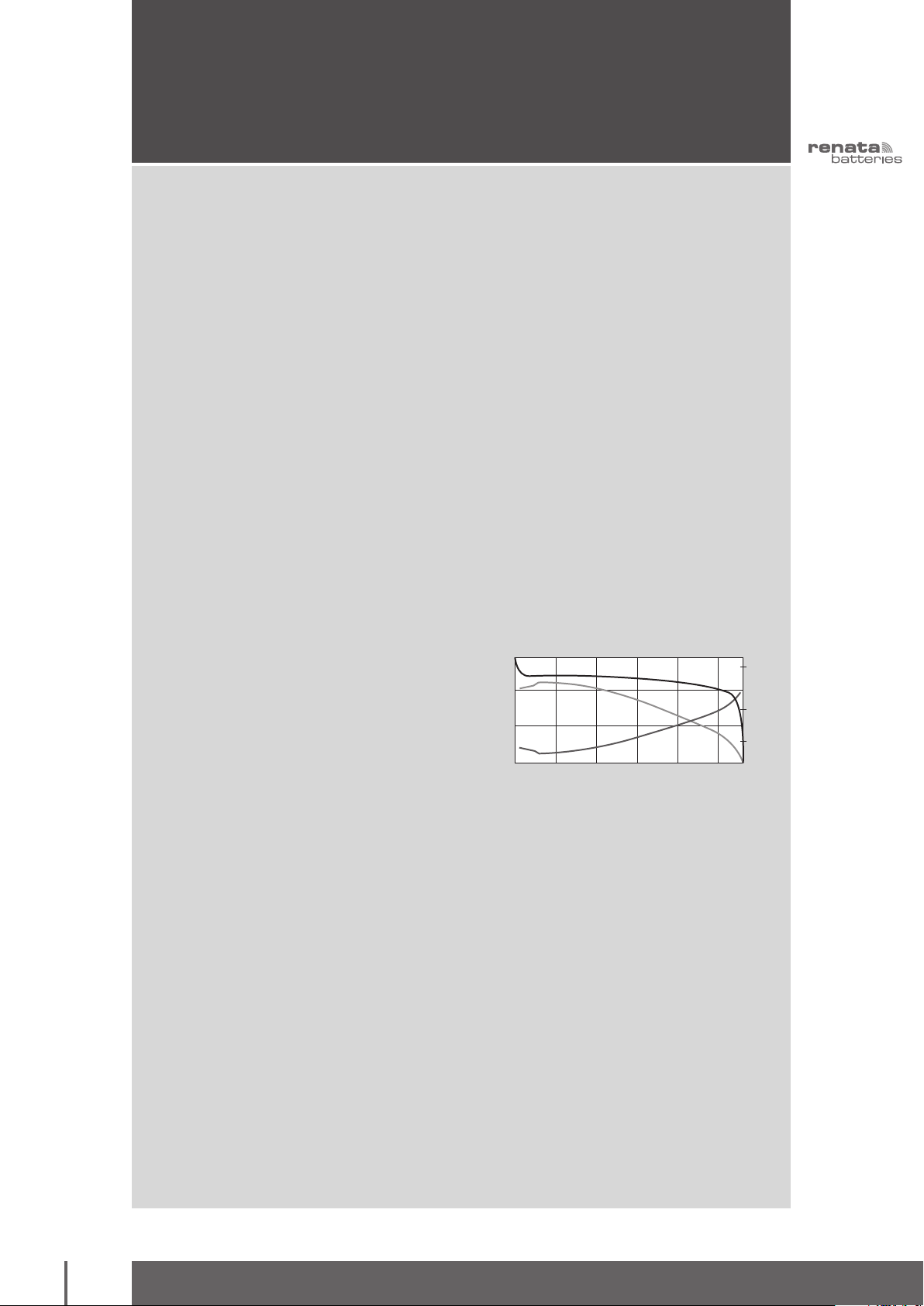
The increase of the overall internal resistance with
increasing discharge level is reported in the figure
below.
Figure 1 Characteristic curve1of a CR2450N cell. Discharge load:
R1=3.32 kOhm. Measurement of internal resistance
during discharge: by applying the load R2=150 Ohm for
1s, every 3 hrs.
1) This curve is intended
as typical data and not
as cell specification.
41
the swiss power source
Frequently Asked Questions (FAQ)
2.8
50
90
20
2.4
400300200200500
2.0
Capacity (mAh)
CR2450N Pulse Discharge 10mA/50ms,
Periode 1s. Cut-off voltage: 2.0V
Voltage (V)
Resistance (Ohm)
V
1
V
2
Ri
General electrical performance
The ageing of the cells at normal conditions (i.e.
oom temperature, max. 40% of relative humidity)
r
will also lead to other physiological increases of
he internal resistance, due to normal ageing
t
phenomena taking place at the electrodes.
Though of limited extent, these types of increases
of the internal resistance are normally to be
expected and must be also taken into account,
when designing a new application.
Exposing the cells to elevated temperatures, then,
can lead to further grow of the passivation films at
the anode, with an additional increase of internal
resistance. Furthermore, increasing the
temperature above 70°C can cause the internal
resistance to abnormally increase (because of
electrolyte leakages and degradation
phenomena). Abuse conditions such as discharge
at elevated currents and short-circuit can also
increase the internal resistance abnormally,
because of the deterioration of cell internal
components.
Which is the voltage drop of the lithium
cell during current pulse?
The voltage drop during a current pulse (V) is
the difference between the cell voltage just before
applying the pulse (Voltage-high, V
) and the cell
1
voltage during the pulse (Voltage-low, V2):
From the above reported formula it also follows
hat the voltage drop strictly depends on the
t
applied pulse itself-particularly on the value of the
. The voltage drop is also
ulse-current (I
p
peak
)
affected by the other parameters that define a
pulse-load: the pulse duration (i.e. how long the
pulse current I
is applied), the pulse period
peak
(i.e. the time between two subsequent pulses), the
frequency with which the pulse trains occur
(i.e. how often the pulse trains are applied to the
battery) and -eventually- the basis-current (i.e. the
current applied between two pulse trains). The
last three pulse parameters affect the voltage
drop during pulse, because their settings affect
the value of the cell voltage just before applying
the pulse ( V1).
An example of voltage and internal resistance
behaviour during a pulse discharge is reported
below (Figure 2).
V = V2- V
It is also expressed by the formula:
V = Ri x I
where Ri (internal resistance) depends on the cell
type and dimensions. In addition, the value of Ri
depends on the temperature and on the discharge
level of the cell (see related section about internal
resistance). Therefore the voltage drop of the cell
will be strongly affected by the temperature and
by the cell's discharge level.
42
1
peak
Figure 2: Pulse-current discharge characteristics
1
of the CR2450N cell.
,
1) This curve is intended
as typical data and not
as cell specification.
www.renata.com

Frequently Asked Questions (FAQ)
Application proper design
Application load
profile and
cut-off voltage
Temperature range
and minimum
operating
temperature
Lithium cell
energy and
power
Application
service life
General electrical performance
What is the maximum pulse current the
ithium coin cells can handle?
l
There are no specified limits for the peak current
value in pulse applications. Instead, current limits
can be defined by means of a series of factors
and practical considerations related to the
electrical application, like the load profile, the
cut-off voltage and the targeted service-life of the
cell in the application. Electrical applications are
normally regulated by a voltage threshold (cut-off
voltage), under which the applications miss the
required electric energy to work and therefore will
shut-down. The cell is the energy/voltage source
in the application; when the voltage during a
pulse is lower than the cut-off voltage, the
application will shut down. A proper design of the
electrical application in terms of electrical load
and cut-off voltage, combined with the choice of
What is the shortest time period for
testing the behaviour of batteries?
It is common to perform accelerated tests to
prove the lifetime of the battery in the application
or to test the performance of different batteries.
According to IEC 60086-1 it is recommended to
discharge the battery for a period of approx.
30 days. With the standard discharge current
given on page 7 of this Designer's Guide one
achieves 100% of the nominal capacity within
these 30 days.
the cell of right energy and power characteristics,
re of paramount importance in order to achieve
a
the targeted service-life of the application. The
utual relation that links application characteris -
m
tics, cell performances and targeted application
services is graphically illustrated below.
Consult Renata experts in order to calculate and
select the cell with the right characteristics for
your application and achieve your goal!
However, also expedited test are possible when
the resulting capacity decrease is taken into
consideration. The limit of the average discharge
current is the max. continuous discharge current
given and explained on page 7. It is not
recommended to perform tests with currents
beyond this limit because the results may not be
typical or they could be misleading. Li/MnO
2
batteries are designed to supply low currents for
several years. Therefore, test results are rather
random when discharging the batteries in very
short time periods with high currents.
the swiss power source
43

Frequently Asked Questions (FAQ)
Influence of temperature on electrical performance
The operating temperatures of lithium coin cells
re given on page 7. Below –30°C the pulse
a
current performance of the cells is significantly
educed, due to the increased internal resistance.
r
Ambient temperatures over the given max.
operating temperature may be possible for a short
period of time. Please ask Renata experts for
advice on this matter.
Has high temperature any detrimental
effect on the cell performance?
Increasing temperature to values above room
temperature will increase the rate of selfdischarge, reducing the available cell capacity –
thus shortening both the service-life and the
shelf-life. The self-discharge of a cell is due to
parasitic reactions taking place at the electrodes,
consuming the electroactive material. As for every
reaction, the rate of these processes is function of
temperature. A simple "rule of thumb" to
determine the self-discharge at a given
temperature is the following: the rate of selfdischarge increases of a factor 2 for every 10
degrees Celsius of temperature increase from
room temperature (20°C). Given that at room
temperature the rate of self-discharge of lithium
coin cells is 1% of capacity loss per year, at 40°C
(for example) the self-discharge rate will be:
(40-20)/10
1% x 2
= 1% x 22= 4% of capacity
loss/year.
In addition to self-discharge considerations, the
maximum storing and operating temperature for
the lithium coin cells must not exceed the given
max. operating temperature, in order to avoid any
electrolyte leakages, leading to reductions of cell
functionality.
Characteristics
Shelf life (temperature / time)
100
80
0
6
0
4
20
0
.1 0.2 0.3 0.5 1 2 3 5 10
0
Remaining capacity (%)
0°C
8
0°C
6
Storage time (years)
Storage characteristics (CR2430)
.5
3
3
2.5
2
.5
1
1
Voltage (V)
0.5
0
0 200 400 600 800 1000
Time (h)
3.5
3
2.5
2
1.5
1
Voltage (V)
0.5
0
0 200 400 600 800 1000
Time (h)
3.5
3
2.5
2
1.5
1
Voltage (V)
0.5
0
0 200 400 600 800 1000
Time (h)
5°C 23°C
4
8.25 k
8.25 k
8.25 k
Fresh cell
storage at 60°C
After 1 year
Fresh cell
at ambient temperature
After 10 years storage
Fresh cell
storage at 80°C
After 3 months
44
Has low temperature any detrimental
effect on the cell performance?
Generally speaking, the performances of a cell at
low temperature are reduced because of the
decreased conductivity of the electrolyte, which
leads to an increase of internal resistance. As a
www.renata.com
consequence, the ability of the cell to deliver high
power is reduced. Especially when designing an
application with high power demand (high current
consumption, like pulse-loads), this factor must be
carefully taken into account.

Frequently Asked Questions (FAQ)
Influence of storage / ageing on electrical performance
Which are the recommended storage
onditions for lithium coin cells?
c
The normal storage of lithium coin cells is made
at temperature between +10°C and +25°C,
never exceeding +30°C (also according to
IEC 60086-1). In this way the maximum shelf-life
(i.e. max. retention of cell performances after
storage periods) of lithium coin cells is achieved.
Storage temperatures above room temperature
will increase the rate of self-discharge, reducing
Influence of contact material
Which contact materials are recommended?
Recommended contact materials:
• Gold plating – provides the most reliable metal
to metal contact under all environmental
conditions.
• Solid nickel – provides excellent resistance to
environmental corrosion.
• Nickel-clad stainless steel – performs almost as
well as solid nickel.
• Nickel plated stainless steel – also a reliable
metal to metal contact (also used for RENATA's
battery holders SMTU/HU series).
• Inconel alloy – provides good electrical conductivity and corrosion resistance.
Never use tin plated contacts since in high
humidity and polluted environments sulfides can
form on the material and creep through pores in
the coating.
the available capacity of the cell. Humidity above
5% R.H. and below 40% R.H. should also be
9
avoided for sustained periods, as these extremes
re detrimental to batteries.
a
Storing the cells at low temperature is also
suggested, but attention must be paid when
transferring the cells to warmer environments,
because of the possibility of having water
condensing on to the cells (risk of short-circuits).
Which contact force and design ensure
best electrical performance and reliability?
The contact force of the contacts should be
between 2 and 10N (ca. 200 to 1000 gf).
Contact design: It is important that contacts apply
sufficient pressure to hold the battery firmly in
place and prevent electrical disconnections (even
under shock conditions). Contacts must be able to
resist permanent set. Furthermore, two contact
points guarantee more reliability than only one.
General FAQs
Can batteries undergo washing processes?
Please use non-conductive cleaning solutions for
the PCB washing process. In conductive solutions,
the batteries are short-circuited, causing
discharge, voltage drop and possibly deterioration
of the cell performance. Use cleaning solutions
that do not attack the polypropylene cell gasket.
the swiss power source
Are Renata lithium cells certified in terms
of safety?
The safety of Renata cells is certified by
Underwriters Laboratories Inc., Northbrook/
IL/USA, under the file number MH14002. See
www.renata.com/content/3vlithium/tech_
also:
safety.php
and the Safety Section in this Guide.
45
 Loading...